Review

Conducting Polymeric Composites Based on Intrinsically Conducting Polymers as Electromagnetic Interference Shielding/Microwave Absorbing Materials—A Review

by
Bluma Guenther Soares
1,2,*,
Guilherme M. O. Barra
3 and
Tamara Indrusiak
4
1
Depto de Engenharia Metalúrgica e de Materiais-PEMM, COPPE, Ilha do Fundão, Universidade Federal do Rio de Janeiro, Rio de Janeiro 21941-972, Brazil
2
Instituto de Macromoléculas, Universidade Federal do Rio de Janeiro, Rio de Janeiro 21941-598, Brazil
3
Depto Eng. Mecânica, Universidade Federal do Santa Catarina, Florianópolis 88040-900, Brazil
4
Centro Tecnológico do Exército, Av. Das Américas, Guaratiba, Rio de Janeiro 28705, Brazil
*
Author to whom correspondence should be addressed.
J. Compos. Sci. 2021, 5(7), 173; https://0-doi-org.brum.beds.ac.uk/10.3390/jcs5070173
Submission received: 4 June 2021 / Revised: 2 July 2021 / Accepted: 2 July 2021 / Published: 4 July 2021
(This article belongs to the Special Issue Feature Papers in Journal of Composites Science in 2021)

Abstract

:
The development of sophisticated telecommunication equipment and other electro-electronic devices resulted in a kind of electromagnetic pollution that affects the performance of other equipment as well as the health of human beings. Intrinsically conducting polymers (ICP), mainly polyaniline and polypyrrole, have been considered as promising candidates for applications in efficient electromagnetic interference shielding (EMI) due to their ease of preparation, light weight, good conductivity and corrosion resistance. One of the important advantages of these materials is the capability to interact with the EM radiation through both absorption and reflection mechanisms thus enlarging the field of application. In this context, this review article describes a recent overview of the existing methods to produce intrinsically conducting polymers and their blends for electromagnetic shielding application. Additionally, it highlights the relationship between preparation methods reported in the literature with the structure and properties, such as electrical conductivity, electromagnetic shielding effectiveness (EMI SE), complex permittivity and permeability of these materials. Furthermore, a brief theory related to the electromagnetic mechanism and techniques for measuring the microwave absorbing properties are also discussed.

1. Introduction

Electromagnetic interference (EMI) is a kind of environmental pollution caused by natural phenomena (such as solar flares, electrostatic discharge, etc.) and by electronic devices [1,2,3,4,5,6,7,8,9]. The widespread use of smart electronic and communication equipment has increased the emission of electromagnetic radiation in a wide range of frequency, depending on the technology involved in their fabrication. This radiation can affect the sensitivity and performance of other electronic devices, causing impacts on several sectors of daily life, including personal mobile phones, communications, bank security, and may can cause health hazards to human beings, when subjected to prolonged exposure [10,11]. Thus, there is a growing concern about the development of materials able to shield from this radiation. The electromagnetic interference shielding efficiency (EMI SE) of a material is based on its ability of attenuating incident radiation through reflection and absorption mechanism [5,6,7,8]. The first phenomenon is promoted by the presence of mobile charge carriers that interact with the EM waves and is important for electrically conducting materials. The absorption mechanism is based on the conversion of EM into heat or other type of energy and/or dissipation of the radiation [1,4]. This characteristic is achieved with electric and/or magnetic dipoles able to interact with the EM radiation. Materials whose protection involves an absorption mechanism as the principal feature are receiving increasing interest because they can avoid self-emission of EM waves besides being important in stealth technology and defense to reduce the radar detectability of strategic targets [12,13].
A good microwave absorbing material should present low density, thin thickness, flexibility and be able to absorb over a wide frequency range. The miniaturization of electronics and tele-communication devices also requires flexible and processable materials that can be easily shaped into different sizes and forms. Therefore, polymeric composites loaded with specific conducting and/or magnetic fillers (also known as extrinsically conducting polymers) have been extensively explored for EMI shielding and microwave absorbing applications [2]. Several important papers and reviews focus on carbon nanoparticles (carbon nanotubes (CNTs), expanded graphite (EG), graphene nanoplatelets (GNPs), carbon black (CB), etc.) as fillers due to their good conductivity, mechanical strength and corrosion resistance [3,4,5]. Jiang et al., presented a good theory related to EMI SE and emphasized the conducting polymeric composites loaded with different conducting fillers [2]. Chandra et al., discussed the ability of hybrid materials, including polymer hybrid composites loaded with carbon−based materials, as EMI shielding materials [14]. Wanasinghe and Aslani recently published a review related to the EMI SE of some non-conventional metal-based materials, including composites with metals in the form of fibers or particles [15]. Intrinsic conducting polymers (ICP), mainly polyaniline (PAni) and polypyrrol (PPy), are also promising candidates for developing microwave absorbing materials due to their versatility of preparation with tunable conductivity, light weight, low cost of the reagents, and high conductivity at microwave frequencies. Moreover, they can interact with the EM radiation through an absorption mechanism. In fact, the EMI shielding properties of neat ICP, mainly PAni and PPy, were reported in the literature as it will be discussed in detail in the Section 4 of the present review. Additionally, several other studies highlight the use of ICP-based hybrid materials for developing materials with outstanding EMI shielding and microwave absorbing properties, in which these ICP were combined with CNTs and graphene and their derivatives and also some metal oxide compounds. Wang published an interesting review in 2014 focused on PAni/inorganic composites mainly prepared by in situ polymerization of aniline in the presence of carbon materials, ferrite and other inorganic materials [6]. They also presented some examples involving PAni with some insulating polymers, like epoxy resin (ER), polyurethane (PU), rubber and poly(vinyl chloride) (PVC) [6]. Jiang et al. also discussed hybrid materials involving conducting polymer and inorganic materials [2]. Recently Lin et al. described different method and applications of composites based on PAni with carbon and/or magnetic materials for microwave absorption purposes [7].
Conducting polymers are brittle materials and hard to process, mold and shape into artifacts. Therefore, several researchers are devoted to studying the use of these compounds as fillers in an insulating conventional polymer matrix [16,17,18]. In view of the importance of ICP in several important applications, this review highlights some recent advances on ICP-based polymeric composites as EMI shielding/absorbing materials. Emphasis will be given on different methodologies to prepare these systems based on ICP as filler dispersed in insulating polymeric matrix as well as coatings for different fabrics. This strategy was not considered in detail in other reviews of a similar topic. Although the conducting nanocomposites based on carbonaceous nanomaterials as fillers have become popular due to the greater accessibility of low-cost carbon materials, like CNT and GNP, the nanocomposites involving ICP present some peculiar characteristics such as anti-corrosion and anti-fouling properties.

2. Electromagnetic Shielding Mechanism

When an EM wave collides the surface of a material, it can be transmitted, reflected and/or absorbed by the material, as illustrated in Figure 1 [6,8,9]. The ability of a shielding material to reduce EM waves is defined by the electromagnetic interference shielding effectiveness (EMI SE). The total EMI SE (SET), given in decibels (dB), can be expressed by the ratio of transmitted energy (Et), represented by transmitted EM wave in Figure 1, and incident energy (Ei), represented by the incident EM wave in Figure 1, as shown in Equation (1) [2,15,19,20]:
SE T   ( dB ) = 20 · log ( E t E i )
The total SE (SET) of a shielding material is equal to the sum of reflection (SER), absorption (SEA) and multiple-internal reflections (SEM) mechanisms, as described in Equation (2) [14,21]:
SE T   ( dB ) = SE A + SE R + SE M
SER is mainly governed by the interaction of the EM waves with the mobile charge carriers (electrons or voids) of the material [8]. Due to the high conductivity, the impedance of the conducting materials is significantly different from the impedance of the free space, thus causing the reflection of the incident wave [4,8]. Traditionally metallic materials, including aluminum, copper, aluminium, stainless steel, etc. have been used as efficient EMI shielding materials that reflect the EM waves. Thus, the SER is influenced by the electrical conductivity (σ) and relative magnetic permittivity (μr) of the material and frequency of the EM waves (f), according to Equation (3) [4]:
SE R ( dB ) = 168 + 10 log ( σ f μ r )
On the other hand, the SEA is favored by the interaction of the EM waves with the electric and/or magnetic dipoles of the material. This process involves the transformation of energy to heat and is usually observed for materials with high dielectric constant and/or high magnetic permeability [22,23]. The SEA is directly proportional to the thickness (d), permeability (μ) and frequency, as described in Equation (4) [2,8]:
SE A ( dB ) = 131 · d ( f μ r σ ) 1 2
Besides reflection and absorption, the EM wave can also interact with the material through multiple reflection mechanism. Generally, porous materials or multi-component composites present multiple reflection mechanisms. The SEM can be neglected in microwave region or when SE ≥ 10 dB [2,23]. However, the multiple reflections should be considered when the EM wave interacts with various surfaces or interfaces (multilayered systems). Multilayered electromagnetic shielding systems present improved microwave absorbing properties due to the contribution of the multi-reflection mechanism [24].
When the EM radiation crosses the material, the strength of the transmitted radiation will decrease exponentially. The distance of EM radiation able to penetrate inside the material is known as skin depth (δ), and constitutes another important parameter that influences the shielding mechanism [2,8,25]. It can be expressed by Equation (5):
δ = 1 π f µ · σ
where f is the frequency of the EM wave, μ is the magnetic permeability and σ is the electrical conductivity.
The equation shows that the skin depth decreases with increasing the electrical conductivity [26]. When the material is a perfect conductor with high conductivity, the skin depth is nearly zero and the EM energy is totally reflected at the surface. In materials with low electrical conductivity, the EM wave can easily penetrate to a large depth [25]. Furthermore, if the EM penetrates a distance of δ, the wave is attenuated exponentially by 37% [27].
The multiple reflections depend on the δ. If the thickness that EM can penetrate within the material is higher than skin depth, the absorption mechanism dominates the SE and multiple reflection can be ignored. However, if the thickness is less than δ, multiple reflections may occur inside the material and this energy can be reflected at internal surface reducing the absorption, consequently decrease the SET [27].

2.1. Loss Mechanisms

When an electric field component of EM wave interacts with dielectric materials a polarization occurs in atom and molecules, thus creating a dipole moment. For conducting materials, the applied electric field induces mobile charge carrier’s movement, generating a current density and consequently an electrical conductivity [28]. Thereby, the electrical physics constant which describes how EM waves affect the dielectric material is known as complex permittivity (εr), Equation (6):
ε =   ε r = ε j ε
where the real part, ε′, indicates the charge storage and the imaginary part, ε″, indicates the dielectric loss [29]. Similarly, for magnetic material the applied magnetic field induces spin rotation and moment dipole [30]. The complex permeability (μr) describes the behavior of the magnetic material with the EM wave, Equation (7):
μ = μ r = μ j μ
where the real part, μ′, indicates the magnetic storage and the imaginary part, μ″, indicates the magnetic loss [29,31].
The dielectric loss is governed by different types of polarization, including ionic, orientational, electronic and interfacial polarization. In microwave region, the polarization process is mainly due to the presence of dipole [26,32]. Dipole polarization occurs when dipoles are aligned to an electric field, presenting a non-zero dipole moment, generating a torque [29]. Interfacial polarization occurs whenever there is an accumulation of charges at the interface of two different materials or two different regions within a material for example, particle/polymer, charge/charge or defect/polymer [32].
The polarization loss can be explained by Debye Equation. According to Debye theory, the complex permittivity can be expressed as Equation (8):
ε r = ε r + ε r 0 ε r 1 + j 2 π f τ = ε j ε
where εr0 and εs are respectively the static and high frequency permittivity, f is the frequency, and τ is the relaxation time.
Equation (8) indicates that the permittivity is associated with a relaxation of dielectric process caused by polarization, the Debye relaxation [33,34]. The polarization induced by some dipoles in response to the applied external EM field undergoes exponential relaxation due to thermal fluctuations when the field is removed. These polarizations can be represented by the Cole-Cole semicircle, where each semicircle represents a relaxation associated with a polarization in ε″ vs. ε′ plot [35,36].
Microwave magnetic loss can be explained by hysteresis loss, natural resonance and Eddy current effect [37]. When an alternating magnetic field is applied to the magnetic materials, a moment in the atom that causes precession is created. This phenomenon is a natural resonance, also denominated ferromagnetic resonance [33]. Hysteresis loss is induced by the permanent movement of the magnetic domains and the rotation of the magnetic moments of the material. The coefficient is measured by vibrating sample magnetometer (VSM) [38]. This loss of energy, also called Eddy Current (C0), can be expressed by Equation (9) [39,40]. When the C0 curves are constant in frequency function, the eddy current loss is the main magnetic loss in that region of frequency:
C 0   = 4   d μ 0 . d 2 σ 3 =   µ ( µ ) 2 f 1

2.2. Absorption Mechanisms

A good microwave absorbing material must present high dielectric and/or magnetic loss and also improved impedance matching conditions with air. An improved impedance matching contributes for the incident EM waves getting into the material without being reflected at the surface. Permittivity and permeability determine the loss mechanisms that justify the EM wave absorption process. From those parameters, it is possible to calculate other properties that strong influences the absorbing characteristics as impedance match, attenuation constant and thickness media [29,41,42,43].
The capability of microwave absorption of a material can be confirmed by determining the attenuation constant (α). The attenuation constant describes the ability of a material in attenuating and dissipating the electromagnetic wave by dielectric and magnetic loss, as described in the Equation (10) [44]:
α = 2 π f c   ( μ ε μ ε ) + ( μ ε + μ ε ) 2 + ( μ ε μ ε ) 2
To achieve an efficient absorbing material, combination of impedance match and a collaborative balance among dielectric and magnetic loss must be achieved [2].
The impedance of a material (Zr) is calculated from εr and μr, according to Equation (11):
Z r = Z 0 ( µ r ε r ) tanh j ( 2 π fd c ) µ r ε r
where Z0, σ, f, c and d are impedance of the air, conductivity material, frequency, light speed and material thickness, respectively. When Zr is similar to the impedance of the air (Z0), the incident EM wave can penetrate into material, avoiding reflection on the air/material interface, thus promoting the EM absorption [45]. This is called impedance match. From the impedance values, it is possible to obtain the reflection loss (RL), a quarter-wavelength matching model and the best configuration of multilayer structure.
The EM absorption performance of an absorbing material can be evaluated in terms of the attenuation of reflectivity or reflection loss. For this kind of measurement, a conducting metal plate is placed behind the absorbing material sample. Reflection loss (RL) is defined as the relationship between the electromagnetic energy reflected (Er) by the material and the energy incident on the material (Ei), Equation (12) [33,46,47]:
RL ( dB ) = 20 log ( E r E i )
The calculation of the RL is based on transmission line theory, from Zr, εr and μr, which is obtained by Equation (13) [48,49]:
RL   ( dB ) = 20   log   | Z r Z 0 Z r + Z 0 |
To improve the impedance match for obtaining better absorption and consequently lower RL value is convenient that material have ɛr ≈ µr [50]. The synergistic effect of those properties permits the dissipation of the EM wave energy as strong dielectric and magnetic loss [19,51].
The thickness of the material can also influence the EM wave absorption. The effect is explained by the quarter-wavelength (λ/4) matching model. In the model, when an EM wave penetrates a material, a percentage may be absorbed and another part will be reflected at the first interface air/material and the second interface material/metal plate. Once the two reflected energy waves have a phase difference of 180°, a cancellation of the phase will happen and the total reflected energy is zero, promoting destructive interference. The ideal absorber thickness (tm) promotes excellent microwave absorption when a cancelation phase occurs between these two reflected energy waves [52]. The model describes the relationship between tm and the peak frequency from Equation (14):
t m = c 4 f | ε r | | µ r |

3. Techniques for Measuring the Microwave Absorbing Properties

There are basically four methods to measure EMI SE of a material: (i) free space method; (ii) shielded box method; (iii) shielded room method or anechoic chamber and (iv) coaxial transmission line method. [53]. In this section, only the two methods mainly employed in scientific works will be briefly described.

3.1. Free Space Method

One of these tests consists of measuring the reflectivity in free space of large samples and usually employs the NRL Arch [54]. This equipment was developed by the United States Naval Research Laboratory (NRL), for testing absorbing materials in a wide frequency range [55,56]. Figure 2 illustrates the system, which consists of a physical arc equipped with a transmitting antenna and a receiver located along the arc at a constant distance from the material to be measured. The arc structure is designed in such a way to keep the antennas pointed towards the center of the material under test, no matter where they are positioned. The test environment must not be affected by reflections from the ground, the sides or the ceiling of the environment where the measurements are being made. For this reason, good quality EM radiation absorbing materials with EM attenuation above 50 dB are usually placed around the arc [57]. The object under analysis is located at a minimum distance from the antennas. A network vector analyzer is connected to the transmitting antenna to provide the signal that generates the frequencies, whereas the receiving antenna is connected to a spectrum analyzer. Before evaluating the sample, calibration is performed by measuring the resulting power reflected from a metal plate as reference (an ideal reflector material). The test material is then placed on the plate and the signal reflected by the sample is measured [56].
Another free space method is based on the radar cross section (RCS) method, which is mainly used for military purposes. In this method, the object under radar detection has a cross section that reveals its location and provides the ratio of scattered power to incident power.
The area of the target depends not only on the frequency and the nature of incident and scattered waves, but also the angle between the incident and reflected signals on the object [28]. RCS is typically used to characterize the target’s properties and not the effects of transmitter or receiver power, the localization of the transmitter or distance from the receiver. RCS is also call echo area [58]. For the stealth technology, a reduction in RCS is mandatory to turn the target invisible to radar detection. The echo intensity can be reduced by using appropriate target shape that can reflect and/or diffract the incident wave in different directions from the radar [59,60]. Other techniques involve the use of radar absorbing materials [12,58,59,60]. The shape is considered the first step to RCS control. Flat surfaces can be avoided as they fully reflect the incident wave. Serrated shapes or shapes different from plane promote dispersed radar waves [60].

3.2. Coaxial Transmission Line Method

The coaxial transmission line method is one of the most used for measuring EMI SE because they can be used in a wide range of frequency. In this method a sample holder (wave guide) containing the sample to be analyzed is inserted into the line, as illustrated in Figure 3. The measurements are taken at specific frequency range using a vector network analyzer (VNA). The incident EM wave coming from Port 1 reaches the sample located in the wave guide. Part of the radiation is reflected returning to Port 1 and the other part is transmitted and detected in Port 2, in transmission/reflection mode. These measurements provide the complex scattering parameters (S-parameter), S11 (or S22) and S12 (or S21) with port 1 and port 2. The S11 parameter is related to the reflected radiation whereas S12 parameter corresponds to the transmitted radiation after crossing the sample. From these parameters, the SET, SER and SEA can be estimated though the Equations (15)–(17) [1,61]:
SE T = 10 log ( T ) = 10   log   | S 21 | 2
SE R = 10   log   ( 1 R ) = 10 log ( 1 | S 11 | 2 )
SE A =   SE T   SE R   SE M
where T is the transmission coefficient and corresponds to the fraction of the incident wave that cross the sample and R is the reflection coefficient and refers to the fraction of the incident wave reflected from the sample surface that returns to the port 1. SEM represents the multiple reflection of the wave in the sample interior.
In the transmission/reflection method (Figure 3—left side), the incident signal emitted from port 1 (or 2), reaches the sample with identical dimensions of the cross-section of the waveguide, and the signal can be reflected, represented by S11 (or S22), transmitted to port 2 (or 1), represented by S21(or S12), or absorbed. In this configuration, it is possible to obtain the following properties: SE, µ′, µ″, ε′ and ε″. The complex permittivity and permeability are calculated from NRW algorithmic [62].
In the reflection method (Figure 3—right side), the sample is backed by a metal plate, being considered a 100% reflective material, with 0% of energy absorption. This configuration is used to determine the RL. In this method, the EM waves goes towards the sample, and the signal can be reflected, represented by S11, or absorbed [26].
The sample holders are waveguides characterized by guiding longitudinal metallic structures, where the EM radiation is propagated. They can be rectangular or toroidal -type wave guides (Figure 4), depending on the measured frequency range and are considered perfect conductors because they are closed system that allows internal reflections on the walls without losing energy [33].
The cross section of the rectangular waveguide determines the evaluated frequency range. For example, for C-band analysis (4 to 8 GHz), the cross-section dimensions are 34.9 and 18.8 mm respectively. For X –band analysis (8.2 to 12.4 GHz), the dimensions are 22.10 and 10.0 mm, respectively; and for Ku-band analysis (12.4 to 18 GHz), the dimensions are 15.8 and 7.9 mm [63,64]. Noting that the higher the frequency, the smaller the cross- section of the waveguide.

4. EMI SE and Microwave Absorbing Properties of Intrinsic Conducting Polymers

4.1. Main Characteristics of Intrinsically Conducting Polymers

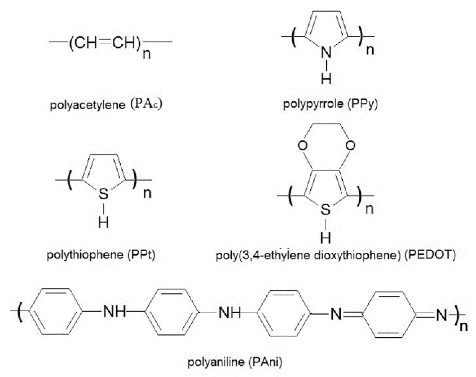
Over the last two decades great interest has been devoted to the development of intrinsically conducting polymers (ICP) for shielding applications due to their distinct electronic properties. This class of polymer is characterized by the presence of a conjugated π-electron system in the main chain (Figure 5). The conjugated polymer (non-doped state) can be converted into a doped state using different doping processes which induce substantial changes in the properties such as electrical conductivity, dielectric properties, EMI SE, microwave absorbing (MA) properties, and others. For example, during the doping process, the electrical conductivity of ICP can be increased, from insulating (10−15 to 10−5 S/cm) to a semiconductor material (10−4 to 103 S/cm).
Among several techniques to produce ICP in their doped state, the electrochemical and chemical oxidative polymerization of an appropriate monomer, such as aniline (Ani), pyrrole (Py) and 3,4 ethylenedioxythiophene (EDOT) are commonly exploited due to their ease to control the structure and properties of these class of polymers [65,66,67,68]. The electrochemical method produces films while powders are obtained by oxidative chemical polymerization. Oxidative chemical polymerization is the preferred method to produce ICP because of its ease of scale-up. The most popular ICP is PAni due to its easy preparation, low cost of the reagents, redox tunability and reversible transformation between the insulating/conducting form by a simple protonation/deprotonation process [65,69]. A huge amount of papers and reviews discuss different procedures for the synthesis of ICP [65,66,67,68,69,70,71,72]. The different methodologies, including temperature, stirring, nature of the protonating agent, doping level, solvent, etc., exert a great influence on the crystallinity and electronic structure (polarons and bipolarons) of the resulting ICP. Thus, by adjusting the synthesis conditions, a good level of conductivity and outstanding EMI shielding effectiveness may be easily achieved.

4.2. EMI SE and Microwave Absorbing Properties of Pure ICP

The first concerns with the use of neat ICP, such as PAni, PPyand polyacetylene (PAc) for EMI SE was reported by Joo and Epstein [73]. For this study, PPy was synthesized by electrochemical technique while Pac and PAni films were prepared using chemical oxidative polymerization of acetylene or aniline in the presence of oxidizing agents.
Neat ICP samples prepared by oxidative chemical polymerization are obtained in the form of powder or thin films directly from the dispersion of these materials. Due to their highly conjugated structure, they are hardly soluble and processable. Therefore, samples for EMI SE studies are generally produced by compression moulding the powder in the pure form or combined with paraffin wax directly in the wave-guide flanges of network analyser. Moreover, thin films may also be obtained by performing the oxidative polymerization in the presence of a suitable substrate.
The EMI SE and microwave absorbing (MA) properties of ICP strongly depend on the electrical conductivity and dielectric properties of the neat ICP, which in turns can be controlled or improved by an appropriate choice of the oxidizing agent and polymerization parameters such as temperature, stirring, etc. For example, Tantawy et al. [74] prepared PAni nanopowder by a free-solvent approach and also by a conventional methodology with solvent. The PAni prepared without solvent displayed higher conductivity (27 S/cm), intermediate crystallinity and superior EMI SE (20 dB) in the X-band frequency range, when compared with those employed conventional chemical synthesis in water.

4.3. The Effect of Dopant on the EMI SE of ICP

The use of functionalized protonic acids as dodecylbenzene sulfonic (DBSA), camphor sulfonic (CSA), naphthalene sulfonic (NSA), p-toluene sulfonic (TSA) or phosphonic acids, and surfactants in an oxidative chemical polymerization of Ani or Py is an interesting approach to improve the processability, thermal stability, increase the solubility of the ICP in common solvents, and improve the and also the compatibility with conventional polymers.
Phang et al. [75] investigated the effect of doubly dopant agents, TSA and dichloro acetic acid (DCA), on the MA properties of PAni. For this study, a toroidal shaped sample with 4 mm thick was employed. Sample with higher conductivity was achieved by using TSA/DCA dopant ratio of 1/1. Moreover, better microwave property was observed in the frequency range of 4–13.5 GHz, with SER and SEA of around 57–64% and 34–41% respectively. Due to the relatively high conductivity, the EM attenuation by reflection is important, thus limiting some applications. The authors did not mention the overall EMI SE for these systems.
Ohlan et al. [76] prepared PAni doped with different contents of DBSA as dopant agent by microemulsion polymerization. Samples with a thickness of 2 mm were produced through compression moulding of the as-synthesized PAni.DBSA powder. Higher electrical conductivity was achieved for the Ani/DBSA molar ratio of 1:3. EMI SE analysis performed in the frequency range of 8.2–12.4 GHz revealed that the SER (due to reflection) decreased and the SEA (due to absorption) increased with the DBSA concentration. The sample prepared with Ani/DBSA = 1:3 presented SER and SEA values at 12.4 GHz of −2.2 dB and −26.5 dB, respectively.
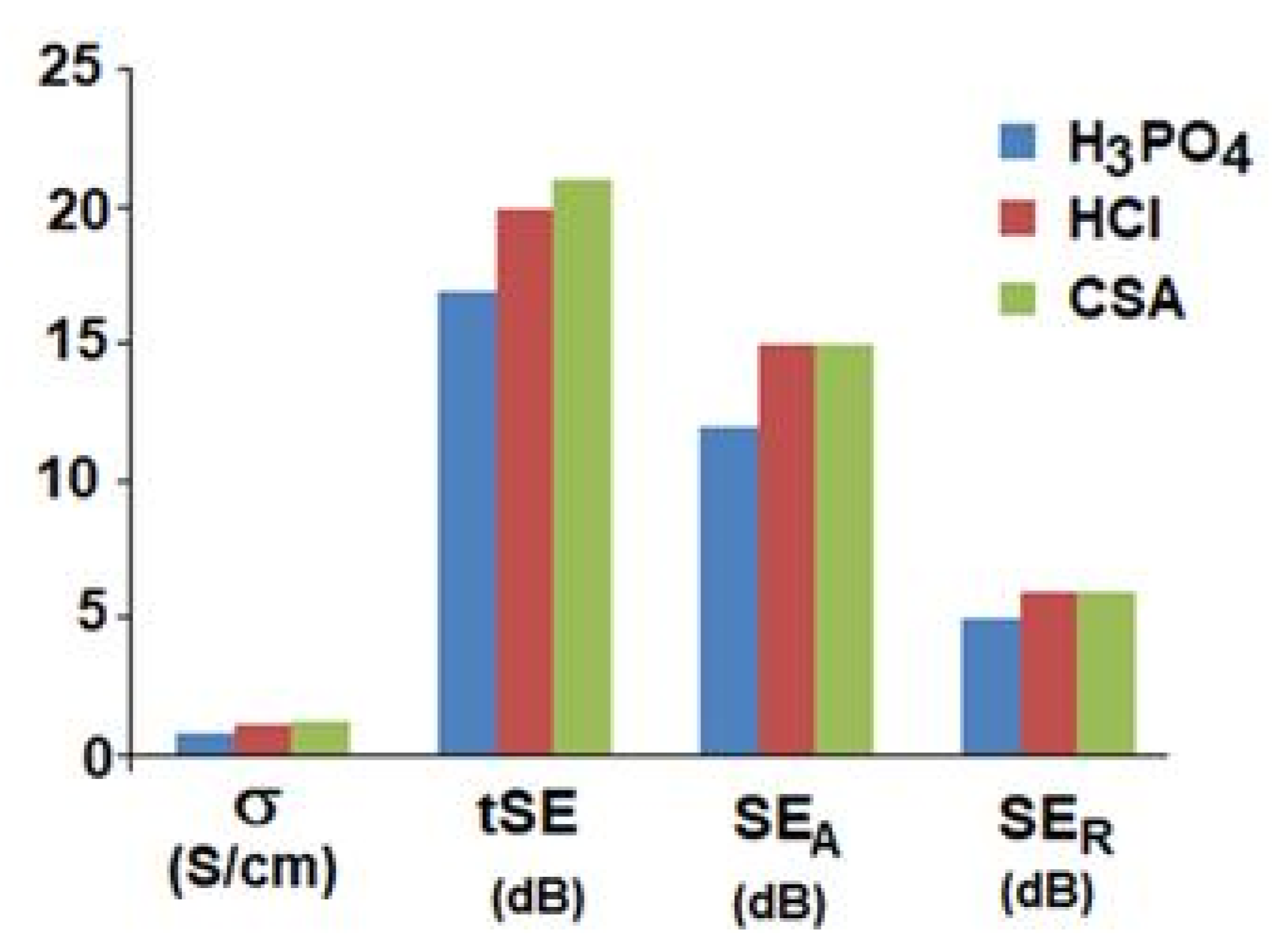
Qiu et al. [77] prepared PAni doped with CSA, (HCl and phosphoric acid (H3PO4). For EMI shielding characterizations, the PAni powder was mixed in the molten paraffin wax in a mass ratio of PAni/paraffin of 40:60 and compression moulded into specimens with 0.35 mm thickness. The counteranion inserted into the polymer chain exerted a great influence on the structure and properties of the doped PAni samples. Figure 6 illustrates the EMI SE at 10 GHz and conductivity of PAni samples doped with different protonic acids. Although the differences in conductivity values were not high, PAni.CSA sample displayed slightly higher conductivity thus contributing for the outstanding EMI SE value of 24–20 dB. The absorption mechanism was more important for all samples. According to the authors, the hydroxyl group of CSA exerts a repulsion effect and some organization of the chains. The crystallinity degree of this sample was also slightly higher.

4.4. Effect of Surfactant on the EMI SE of ICP

The electrical properties of neat ICP can be also improved by using surfactants during the oxidative polymerization. In this regard, the effect of various concentration of sodium lauryl sulphate (SLS) (5, 10 and 30 mM) on the electrical conductivity and EMI SE values of PPy prepared by direct chemical oxidation of Py was evaluated [78]. It was demonstrated that the PPy particle size decreased from 53 to 28 nm with increasing anionic surfactant content. Electrical conductivity as high as 22 S/cm and EMI SE values of 49 dB in the frequency range of 12–18 GHz were achieved for PPy prepared in the presence of 30 mM of SLS.
The effect of cationic surfactant such as the cetyltrimethylammonium bromide (CTAB) on the structure, electrical properties and EMI SE of PAni was evaluated [79]. For this study, PAni was prepared by inverse emulsion polymerization of Ani in toluene using a mixture containing DBSA and CTAB. For EMI shielding characterizations, the PAni powder was compression-moulded into specimens with 2.0 mm thickness and analysed in the X-band (8.2–12.4 GHz) frequency range. PAni.DBSA prepared without the addition of CTAB presented electrical conductivity value of 0.37 S/cm and total EMI SE of around 25 dB. The presence of CTAB in a CTAB/DBSA molar ratio of 0.5 resulted in a significant improvement of conductivity and EMI SE, whose values stayed in the range of 2.2 S/cm and 45 dB respectively. The outstanding electrical properties was attributed to the morphology characterized by the presence of thin lamellar structure with thickness around 100–150 nm.
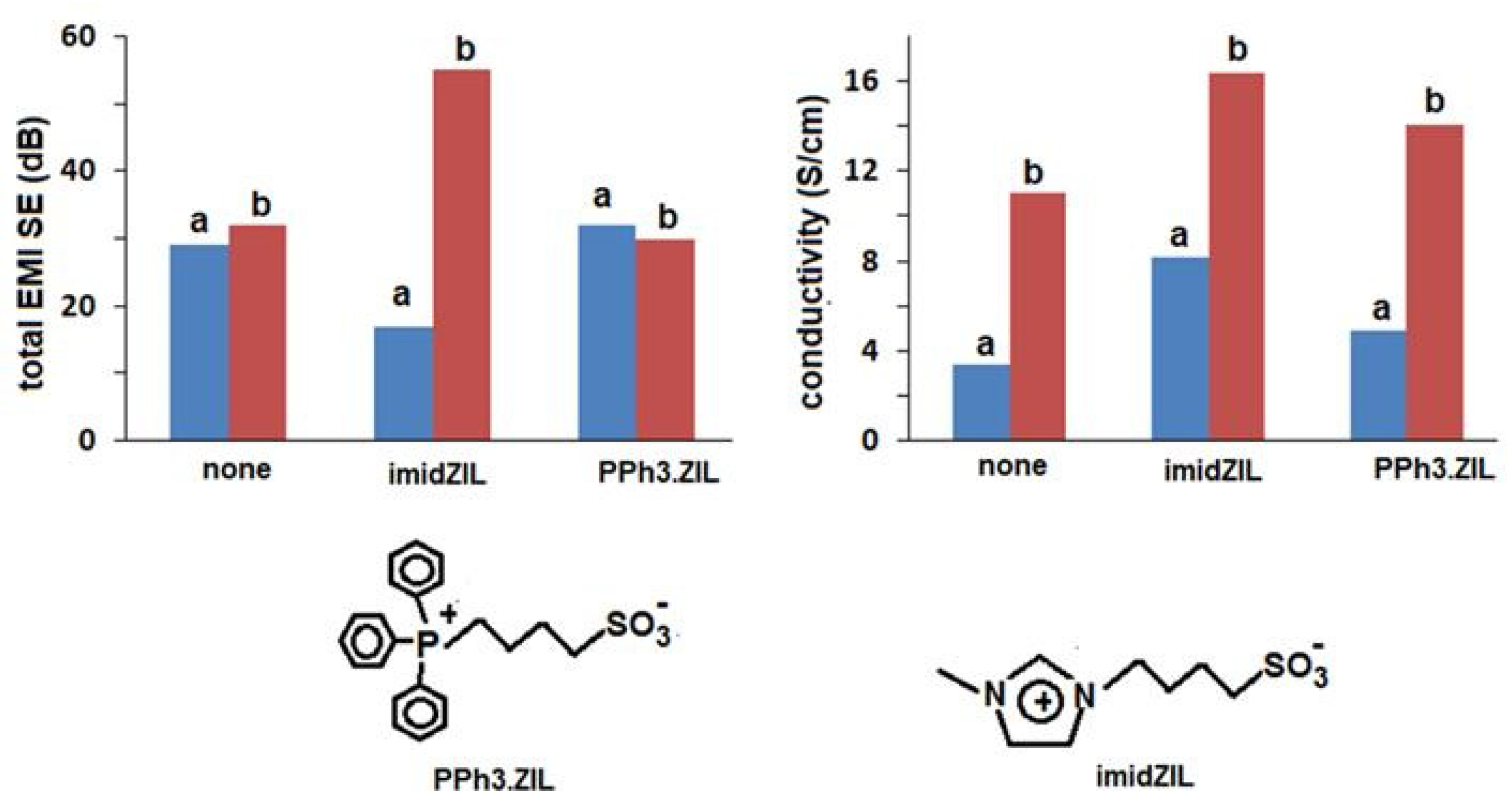
In another work reported by our research group, DBSA and zwitterionic ionic liquids based on imidazolium and triphenyl-phosphonium containing sulfonate group were also used as dopant systems and CTAB as the surfactant [80]. The presence of CTAB promoted a significant increase in the electrical conductivity value of PAni.DBSA and a slight improvement of the attenuation of the EM radiation from 28 dB to around 32 dB. As also reported in other works in the literature, CTAB acts as soft template for the propagating species, and induces the orientation of PAni chain, thus favouring the delocalization of charge [81]. The effect of CTAB and ionic liquid on the conductivity and total EMI SE values of PAni.DBSA was also illustrated in Figure 7.
The combination of CTAB and the zwitterionic-based imidazolium ionic liquid significantly increases the EMI shielding efficiency of the PAni.DBSA sample, whose values around 55 dB were achieved for sample with 1 mm thickness [80]. All samples presented a higher contribution of reflection mechanism to the overall EMI SE.

4.5. EMI SE of ICP s Thin Films

Thin films based on neat ICP layers were also produced by in situ polymerization of the monomer on appropriate substrates. For example, PPy films with good MA properties and EMI SE were obtained through the in situ polymerization of Py on an alumina substrate [82,83,84]. PPy.H2SO4 prepared with ammonium peroxydisulfate (APS) as oxidant with thickness of 1.5 μm displayed EMI SE value of around 10 dB at around 9.2 GHz [82].The same research group used a similar approach for studying the effect of different oxidants as APS, ferric chloride (FeCl3) and potassium persulfate (K2S2O8) [83]. The polymerization carried out with K2S2O8 resulted in PPy.H2SO4 thin film with 5.2 μm thickness, conductivity of 0.13 S/cm and a maximum EMI SE of 14.75 dB at 10.2 GHz. The outstanding behavior was attributed to the compact and dense globular morphology observed for this sample. In another study, PPy thin film with 4.38 μm thickness deposited onto alumina coupons was prepared with different Py concentration, without protic acid [84]. The highest EMI SE of 19 dB was observed in the Ku-band frequency region for the sample prepared with 0.2 M of monomer concentration. This sample also presented minimum RL of −30.8 dB at 14.2 GHz. The authors attributed the outstanding performance to the cauliflower-like morphological structure of this sample, which should promote multiple reflection or scattering phenomena of the EM wave inside the cores of the PPy hemispheres.
Thin films of PAni.CSA were also prepared by casting a solution in m-cresol onto a glass substrate [85]. The film peeled of the substrate, with a thickness of 0.18 mm, resulted in an overall EMI SE of around 45 dB at X band and 43 dB at Ku band. The m-cresol acted as a solvent and a secondary dopant. In spite of the very interesting response in terms of EMI SE, this system presents significant limitations due to the use of m-cresol which is a very toxic solvent.
Summarizing, neat ICP as compressed powder samples or even thin films have been considered as EM SE and MA materials. Table 1 summarizes some studies concerning the synthesis of ICP, as well as the maximum electrical conductivity and EMI SE values achieved for these materials.
It is difficult to compare the results because of different procedure used for the synthesis, the thickness of the samples and the frequency range analysed. Moreover, some PAni as powder was compounded with paraffin wax, thus affecting the amount of dielectric/conducting characteristics for analysis. The presence of surfactant during the synthesis affects the morphology and contributes for an increase of conductivity and total SE. Additionally, for similar systems, higher conductivity usually increase the SET due to the higher concentration of free charge carrier able to interact with the EM radiation. The most drawbacks of these materials is the brittle nature of ICP, thus limiting their application in the present form.

4.6. EMI SE of ICPs—Based Hybrid Materials

The EMI shielding properties by absorption mechanism are very useful to control self-emission of the EM radiation and also to protect military targets through the well-known stealth technology. The MA properties depend on the magnetic permeability, dielectric permittivity and conductivity of the material. A good absorbing material must present high EM attenuation in a determined frequency and a wide bandwidth with RL less than −10 dB (more than 90% of absorption). In this context, ICP have been combined with other dielectric and/or magnetic materials to enhance their ability of absorbing the radiation. Carbon materials have been used as dielectric partners for ICP-hybrid materials whereas magnetic materials have been also used to attenuate the incident radiation due to the magnetic loss. Gupta et al. [86] reported the EMI SE of hybrid materials constituted by natural graphite flakes (NGF), PAni and CNT. PAni was first synthesized in the presence of NGF particles. Then, the PAni@NGF hybrid containing 5% of NGF was mixed with different amounts of CNT using solvent approach. The PAni@NGF hybrid presented SET of around 46 dB in all frequency range (12.4–18 GHz). The addition of CNT resulted in additional increase of conductivity and SET. In all hybrids, the absorption phenomenon dominated the shielding effectiveness, which was attributed to the high dielectric constant and dielectric loss.
PAni nanorods were also prepared in the presence of amino-functionalized graphene nanoplatelets (GNPs) for developing MA materials [87]. The product was mixed with paraffin wax (a transparent compound for EM radiation) in a proportion hybrid/wax = 1:2. The RL was calculated for different thickness, according to Equation (13). The authors reported minimum RL values of −51 dB at 11.2 GHz with a thickness of 2.5 mm. Moreover, the bandwidth less than −10 dB (90% of EM absorption) was around 4 GHz (from 9.6 to 13.6 GHz) [87]. Other examples of ICP/carbon hybrid materials with MA properties are summarized in Table 2 and can also be found in a recent review published by Lin et al. [7]. The symbols ICP@filler indicates that ICP was synthesized in the presence of the carbon filler.
Magnetic materials were also combined with ICP to improve the microwave absorbing properties. Blending ferrite and other metal oxides with ICP have been chosen to improve the absorption properties of the hybrids due to the dielectric and magnetic characteristics of each component. The ferromagnetic nanoparticles in a nanocomposite usually reduce the impedance mismatch at the air/material interface. The combination of magnetic and electric properties by using hybrid materials usually contribute for an attenuation of the EM radiation in a broadband of frequencies. In fact, some of these systems are able to attenuate more than 90% of the EM incident radiation (RL < 10 dB) in a wide frequency range, which is very important for several applications in electro-electronic devices. A great number of examples can be found in the literature and a few examples are summarized in Table 3.
Iron oxides are considered very popular and inexpensive materials and were compounded with different ICP. Mahmoudi- Badiki et al. synthesized PAni in the presence of F3O4 previously prepared by coprecipitation (Fe3O4-cop) and hydrothermal methodology (Fe3O4-hyd) [88]. The presence of Fe3O4-hyd resulted in hybrid with higher EM attenuation, reaching minimum RL value around −31 dB for the sample with 3.5 mm. The better response of the PAni@Fe3O4-hyd is due to the peculiar morphology and the higher magnetic properties.
Zhou et al. [89] prepared Fe3O4 hollow microsphere surrounded by PEDOT as a core-shell morphology and studied the effect of the Fe3O4/PEDOT composition on the RL value. Hybrid with 20% of PEDOT resulted in RL of around −30 dB at 9.5 GHz with 4 mm thickness. Increasing the amount of hybrid in the blend with paraffin wax resulted in an increase of RL (lower absorption) probably because of the increasing of the conducting component and the stronger contribution for the reflection mechanism.
PEDOT−based hybrids were prepared by one-step method using FeCl3, which plays the role of oxidant for the synthesis of PEDOT and the precursor for the preparation of iron oxide together with Fe2+ ion [90]. The formation of α-FeOOH (goethite) or maghnemite (γ-Fe2O3) is controlled by adjusting the [Fe3+]/[Fe2+] molar ratio. The better response was observed when [Fe3+]/[Fe2+] corresponded to 3.0, although the saturation magnetization was lower than the other hybrids. In this case, RL value around −44 dB at 8 GHz was observed for samples with thickness of 4 mm. A similar methodology was also employed to prepare PPy/PEDOT@α-FeOOH [91]. The best calculated RL value of −16.9 at 15.8 GHz was observed for the hybrid prepared with [Py]/[Fe2+] of 1.0. Increasing the amount of Py in the synthesis, resulted in a hybrid with higher conductivity but decreased EM attenuation.
Barium hexaferrite (BaFe12O19, BHF) was also employed as the partner for preparing PAni/BHF hybrid materials with good EMI shielding effectiveness [92]. For the sample with 3 mm thickness and dispersed in 50% of paraffin wax, neat PAni displayed SET of around 12 dB at 12 GHz. The addition of BHF increased the SET to 20 dB up to 8% of BHF. Beyond this concentration, the efficiency decreased as the amount of BHF increased but the SET was still higher than neat PAni, except for those containing 25 and 40% of BHF. Similar behavior was observed for the samples with 5 mm thickness, with SET value of 28.6 dB with 8% of BHF. According to the authors, the decrease in EMI SE with higher amount of BHF was due to the interruption of the continuity of the PAni phase, resulting in small ohmic losses, but by adding 8% of BHF, the dispersed magnetic particles can contribute for the attenuation, due to multiple scattering of EM radiation. Increasing the amount of BHF, the agglomeration of the nanoparticles decreases the polarization effect at the interface due to a decreasing of the interfacial area. The combination of CNT with PAni and BHF resulted in a significant increase of EM attenuation where SEA values of −36 dB at 12.4 GHz was reached by using 20% of CNT in the ternary blend [93]. As observed in other report [93], the presence of high amount of ferrite resulted in very low EM attenuation.
Choudhary et al. also investigated the effect of coral-shaped yttrium iron garnet (a soft ferrimagnetic material) on the EMI SE of the corresponding PAni-based hybrids [94]. Also in this system, the best amount of the magnetic YIG corresponded to 20%. The SET increased from around 22 dB at 18 GHz for pure PAni to around 44 dB with the presence of 20% of YIG. This behavior was also explained by the multiple dielectric relaxation processes and an increasing of interfacial polarization promoted by the morphology of the nanoparticles.
The combination of ferrite with ICP usually improves the absorbing properties in a wide frequency range due to a synergistic effect of dielectric and magnetic properties together with the tuned electrical conductivity. For example, the PAni@Zn0.5Ni0.4Cr0.1Fe2O4 presented slightly lower RL value (better attenuation) than neat PAni, but a significant increase of the bandwidth with attenuation higher than 90% [95]. According to the examples presented in Table 3, outstanding performance in terms of minimum RL and also the frequency range with EM attenuation superior to 90% (<−10 dB) can be achieved by using a combination of ICP, a carbon nanomaterial like GNP and a ferrite. This result may be due to several factors, including multi-reflection due to an increase of interfaces within the material, the improved dielectric and magnetic properties and the impedance matching between the air and the material at the surface, which permits the wave to penetrate into the material without reflecting back at the surface.
Table 2. Microwave absorbing properties of Hybrid materials based on ICP and carbon materials.
SystemFrequency Range (GHz)EM Absorption (dB)ThicknessBandwidth (<10 dB) (GHz)Obs.Ref.
PAni@NGF12–18−45 (SEA)2.5-5% NGF/pressed powder[86]
PAni@NGF/CNT (90/10 wt%)12–18−80 (SEA)2.5-5% NGF/pressed powder[86]
PAni.HCl@NH2-GNP11.2−51.5 (RLmin/calc)2.54 (9.6–13.6 GHz)65% of paraffin wax[87]
PEDOT@RGO6.9−13.4 (RLmin/calc)2.5-50% of paraffin wax[96]
PAni.HCl@GNP (6.5/1 wt)8.5−25.9 (RLmin)2.0–4.0 80% of paraffin wax[97]
PAni.HCl@GNP (5000/1 wt)12−25 (RLmin/calc)24 (10–14 GHz)40% of paraffin wax[98]
PAni.HCl@CNT (75/25 wt%)12–18−28 (SEA)2-Pressed powder[99]
PAni.DBSA/graphite (10/90 wt%)8–12−17 (SEA)2-Pressed powder[100]
PAni/CB (70/30 wt%)11.5−40 (RLmin/calc)2-35% of epoxy resin[101]
CB = carbon black; RGO = reduced graphene oxide.
Despite the very attractive EMI SE/MA properties revealed by these interesting works described above, neat ICP are insoluble in common organic solvents and not melt-processable in their conductive form due to their highly conjugated structures. Moreover, they have poor mechanical properties and low thermal stability when compared to convectional polymers, which limits their use for shielding applications. The hybrids also present similar drawbacks. In fact, almost all systems discussed in this topic were prepared by pressing the powder directly to the wave guide (with toroidal or rectangular shape) or blending the powder with a specific amount of paraffin wax to facilitate the measurement. However, it is hard to build some devices mainly thicker devices, because it is impossible to keep the mechanical integrity and shape. To overcome these drawbacks, several interesting techniques have been reported in the open literature, in which ICPs are used as filler into insulating polymer matrix or as coating in fabrics and other substrate.
Table 3. Microwave absorbing properties of Hybrid materials based on ICP and ferrite-based materials.
SystemFrequency Range (GHz)EM Absorption (dB)ThicknessBandwidth (<10 dB) (GHz)Obs.Ref.
PAni@Fe3O4- hyd8.4−31 (RLmin)3.51.2 (8.4–9.6 (GHz)paraffin wax[88]
PEDOT@Fe3O4-hollow (20/80 wt%)9.5−30 (RLmin)4.0-80% of paraffin wax[89]
PEDOT@α-FeOOH8.0−44 (RLmin)4.0-50% of paraffin wax[90]
PPy@α-FeOOH15.8−16.9 (RLmin)2.0 70% of paraffin wax[91]
PAni/BaFe12O19 (42/8 wt%)12−16.5 (SEA)3.0-50% of paraffin wax[92]
PAni@BaFe12O19/CNT (40/40/20 wt%)12.4−36.4 (SEA)4.5-30% of paraffin wax[93]
PAni/YIG (30:20 wt%)18−40.2 (SEA)4.0-50% of paraffin wax[94]
PPy@GNP10.2−12.1 (RLmin/calc)2.04.2 (8.2–12.4 GHz)Pressed powder[102]
PPy@Fe3O410.3−14.0 (RLmin/calc)2.04.2 (8.2–12.4 GHz)Pressed powder[102]
PPy@GNP/Fe3O49.84−18.3 (RLmin/calc)2.04.2 (8.2–12.4 GHz)Pressed powder[102]
PAni11.5−25.0 (RLmin)2.05.1(9.5–14.6 GHz) [95]
PAni@Zn0.5Ni0.4Cr0.1Fe2O4(100:25 wt%)13.6−26.3 (RLmin)2.07 (10–17 GHz)50% of paraffin wax[95]
PEDOT/GNP10−12.5 (RLmin)2.02 (8.5–10.5 GHz)50% of paraffin wax[103]
PEDOT@NiFe2O49.3−9.8 (RLmin)4.0-50% of paraffin wax[103]
PEDOT@NiFe2O4/GNP15.6−45.4 (RLmin)2.04.6 (12.6–17.2 GHz)50% of paraffin wax[103]
PAni.DBSA@CoFe2O4(33:67 wt%)12–18−21.5 (SEA)--Pressed powder[104]
PAni.DBSA@CoFe2O4(50:50 wt%)12–18−18 (SEA)--Pressed powder[104]
PAni.TSA/CoFe2O4(50:50 wt%)8.1−28.4(RLmin)--Pressed powder[105]
PEDOT:PSS/Fe3O4/RGO (50:50 wt%)13−42.8(RLmin)1.86.4 (8–14.4 GHz)50% of paraffin wax[106]
PEDOT@RGO/CoFe2O410.7−51.1 (RLmin/calc)2.03.1 (9.4–12.5 GHz50% of paraffin wax[96]
YIG = yttrium iron garnet.

5. EMI SE and Microwave Absorbing Properties of Composites Containing ICP

5.1. ICP as Filler in Insulating Polymer Composites

ICP cannot be properly processed and shaped into artefacts due to their high brittle character, low solubility in common solvents and poor processability. Therefore, dispersing the ICP inside an insulating polymeric matrix constitutes a versatile approach for developing conducting materials. This way, flexible and processable conducting composites can be produced using cost-effective and scalable procedure. Moreover, tuneable electrical and dielectric properties can be designed by choosing appropriate amount of ICP, and preparation methodology, such as, mechanical mixing, solution/dispersion mixing and the in situ polymerization of the ICP in the presence of the insulating polymer. The methodology depends on the nature of the matrix and exerts significant influence on the conductivity and EMI SE/microwave absorbing properties of the final material.

5.1.1. Mechanical Mixing

Mechanical mixing is considered a versatile strategy for preparing conducting polymeric composites based on thermoplastic and rubber matrices, due to the possibility of large-scale production and has been extensively employed to produce carbon materials-based conducting composites [107,108,109]. However, this technique is not common for ICP- based composites due to the low thermal stability of these fillers at the processing temperature, which may result in a decrease of conductivity and also EMI SE. Moreover, the shear forces used in the melting process may not be enough in some cases to provide a good dispersion of the ICP particles inside a polymer matrix, thus requiring great amount of filler to attain the percolation threshold, that is, the insulator—conductor transition. For blends involving PAni, functionalized protic acids such as DBSA and CSA are frequently used as doping/protonating agents to improve the compatibility with the polymeric matrix. The preparation of the conducting PAni can be carried out by re-doping process of the emeraldine base (EB) or through the one step emulsion polymerization of Ani in the presence of these protonic acids. The methodology for preparing PAni has a significant influence on the conductivity of the corresponding composite and also the EMI SE. For example, PAni.DBSA prepared by bulky redoping process of EB was melt mixed with ethylene−vinyl acetate copolymer (EVA) [110] and styrene−butadiene−styrene block copolymer (SBS) [111] and compression-moulded into specimens with 2 mm thickness. The presence of 30% of PAni.DBSA in EVA and SBS matrices resulted in composites with overall EMI SE (SET) values around 32 dB and 23 dB, respectively, in the X-band frequency range. In fact, the resistivity values of EVA/PAni.DBSA and SBS/PAni.DBSA were in the range of 103 and 105 Ω.cm, respectively, which account for the higher SET of the former system. Nevertheless, blends whose PAni.DBSA was prepared by one step emulsion polymerization presented lower EMI SE. This feature was observed for blends with SBS [111] with similar thickness, whose EMI SE value was around 4 dB for the composite with 30% of PAni.DBSA. Very low EMI SE value (around 5.5 dB) was also found for poly (vinylidene fluoride-co-hexafluoropropylene) (PVDF-co-HFP) melt blended with 30% of PAni.DBSA prepared by one step emulsion polymerization [112], which may be due to the poor dispersion of PAni prepared by this methodology. The bad performance for the last system may be also attributed to the thickness of the sample (1 mm) and the injection moulding process, which has been reported to provide lower conductivity and worse EMI SE values [113]. The higher conductivity and EMI SE values observed for the blends involving PAni.DBSA prepared by bulky redoping process may be attributed to an additional doping process during the melt processing due to the presence of excess of DBSA. Additionally, the presence of molecular DBSA improves the processability of the blend and consequently the dispersability of the filler.
PAni doped with TSA, prepared by solution re-doping process was also melt blended with poly(ethylene-co-octene) (EOC) [114]. An EM attenuation of around 80% was observed in the X-band frequency range (8–12 GHz) when 37% of PAni.TSA was incorporated into the EOC matrix. This is considered a low performance. Koul et al. studied the effect of mixed organic dopants (DBSA and TSA) on the EMI SE of acrylonitrile-butadiene-styrene copolymer (ABS)/PAni composites [115]. The authors reported EMI SE value of 36 dB at a high frequency (101 GHz) for the blend containing 30% of PAni, although the resistivity stayed in the range of 106 Ω.cm.
EMI shielding composite materials were also developed using vulcanized rubber as the matrix. For example, Al- Ghamdi et al. [116] blended different amounts of PAni doped with H3PO4 with natural rubber (NR) in a two roll-mill together with a sulphur-based vulcanizing agent. The presence of 30% of PAni.H3PO4 resulted in composites with overall EMI SE value of around 60 dB at 12 GHz, which is considered an excellent EM attenuation performance. Yuping et al. [117] studied the effect of PAni.HCl on the EMI SE of the vulcanized silicone composites in the low frequency range (3–1500 MHz). EMI SE values around 16–19 dB were reported for composites loaded with 50% of PAni.HCl.
Ramoa et al. [118] prepared PPy in the presence of HCl and DBSA and melt blended these conducting polymers with thermoplastic polyurethane (TPU). They also synthesized PPy.HCl and PPy.DBSA in the presence of clay (MMt) and evaluated the effect of different parameters on the conductivity and EMI SE of the corresponding TPU composites. The addition of 30% of PPy.HCl and PPy.DBSA in the composites resulted in total EMI SE of 7.1 dB and 7.2 dB, respectively, for samples with 2 mm thickness. The presence of clay increased the EMI SE to values corresponding to 10.9 dB and 16.6 dB, respectively. Although clay is an insulating filler, it was able to orientate the PPy chain, thus improving the conductivity and EMI SE. In fact, conductivity values of around 10−8 S/cm and 10−2 S/cm were observed for TPU/PPy.DBSA (30%) and TPU/Mt-PPy.DBSA (30%), respectively. Moreover, the EM through absorption mechanism was enhanced with the presence of clay. The last composite displayed EMI SE as high as 36.5 dB for sample with 5 mm thickness.
The microwave absorbing properties were also evaluated for systems involving poly(ethylene-co-propylene-co-5-methylene-2-norbornene (EPDM), poly(styrene-co- -butadiene) (SBR) and polyurethane (PU)loaded with PAni [119,120,121]. For these studies, the doping process of PAni in the non-conductive form (EB) was performed during the melt mixing of polymer matrix and the protonating agent. The MA properties, characterized by reflectivity, were measured at X-band frequency range, either on a NRL arch equipped with two horn-type antennas [119] or with a co-axial transmission system equipped with waveguide [120]. EPDM loaded with 30% of PAni.DBSA displayed reflectivity value (RL) of around −10 dB, which means an attenuation of the EM incident radiation by absorption mechanism of 90%. SBR/PAni.DBSA systems were also combined with poly(styrene sulfonic acid) (PSS) as additional doping agent, using a PAni(EB)/DBSA/PSS weight ratio corresponding to 1:2:0.25 [120]. The EM attenuation increased at higher frequencies, reaching RL values of around −6 dB at 12 GHz and −20 dB at 11.5 GHz for the blends loaded with 30% and 50% of PAni.DBSA, respectively.
Similar redoping approach was employed to prepare conducting blends constituted by PU bi-component and 15% of PAni doped with CSA [121]. The authors studied the effect of the redoping procedure of EB (solution versus melt processing doping), the EB/CSA molar ratio and mixing temperature on the RL of the corresponding composites in the X-band frequency range. The authors concluded that the CSA concentration exerted more influence on the EM attenuation than the doping methodology. In fact, the composite prepared with EB/CSA = 1:2 displayed RL value of around −2.5 dB when compared with that prepared with EB/CSA = 1:3 (−23.3 dB at 11.5 GHz). The authors attributed the better reflectivity of the later system to the higher conductivity.
Recently, PAni.DBSA prepared by emulsion polymerization was dry blended with PVDF as powder using ball-milling approach followed by compression moulding at 220 °C. The corresponding composite, 1 mm thick, containing 43% of PAni displayed EMI SE around 18–20 dB in the X-band frequency range [122]. This result was superior than that obtained by in situ polymerization, which could be attributed to the formation of co-continuous structure with a dense conducting phase of PAni at the interface between the PVDF particles. Table 4 summarizes the EMI SE properties of some PAni-based composites prepared by melt mixing. Except for the PVDF-co-HFP/PAni.DBSA [112] and ABS/PAni.DBSA/TSA [115] systems, the blends that presented good EMI SE performance also displayed acceptable conductivity values, indicating that the conductivity is important for improving the shielding performance, due to the interaction of the EM radiation with the polaron/bipolaron charge and also with the dipoles. Regarding PVDF-co-HFP/PAni.DBSA system [112], PAni was prepared by emulsion polymerization and should display poor dispersion in the polymeric matrix which decreases the possibility of EM interaction with the conducting particles. Although the conductivity was not high, the ABS/PAni.DBSA/TSA system presented high EMI SE but at very high frequency, 101 GHz.

5.1.2. Solution/Dispersion Methodology

PAni in the conducting form (emeraldine salt—ES) is hardly soluble in common solvents. The solubility is increased when organic protic acids are used as the protonating agent. Thus, the systems treated in the present section consist of dispersing PAni as powder in a solution or dispersion of the insulating polymeric matrix. Usually, this procedure provides PAni-based systems with better conductivity and EMI shielding performance than that involving melt mixing owing to the better dispersion of the filler inside the polymeric matrix.
Sudha et al. [123] dispersed PAni or PAni/bentonite hybrid filler doped with DBSA and 3-pentadecylphenol-4-sulphonic acid (3-PDPSA) in toluene solution of EVA copolymer. After evaporation of the solvent, the material was compression moulded. PAni doped with DBSA or 3-PDPSA alone or in combination with clay was prepared by one step emulsion polymerization. The authors reported EMI SE value of around 55 dB for the composite containing 5% of PAniDBSA or PAni.3-PDPSA, whereas the conductivity stayed in the range of 10−3 S/m. For these studies, samples with 2 mm thickness were measured in the frequency between 2 and 8 GHz. Increasing the amount of PAniDBSA or PAni.3-PDPSA to 20%, EMI SE values as high as 72.5 dB and 75.7 dB were achieved, respectively. Although clay is an insulating material, the presence of clay improved the EMI SE, which was attributed to the multi-reflection mechanism induced by the high interfacial area of the nanoclay.
Recently, Peymanfar et al. [124] prepared PAni.DBSA/polyacrylonitrile (PAN) blends by solution process in dimethylformamide (DMF). The authors prepared PAni.DBSA with different Ani/DBSA molar ratio (10.0; 7.5; 5.0; 2.5) in order to tune the energy band-gap and consequently the MA and EMI SE properties. The RL of PAni/PAN composites with different thickness was investigated in the frequency range from 8 to 18 GHz (X-band and Ku-band) as a function of the Ani/DBSA molar ratio used in the PAni.DBSA synthesis. The authors did not clearly report the proportion of PAni.DBSA in the blend but all samples presented an overall EMI SE higher than 7 dB over the entire X- and Ku-band frequencies. Moreover, a minimum RL of −84.4 dB at 9.63 GHz was achieved for the blend prepared with PAni2.5 (Ani/DBSA = 2.5) and thickness of 2.75 mm. This blend also presented a bandwidth as wide as 7.05 GHz at RL < −10 dB (corresponding to 90% of EM attenuation) with only 2.25 mm in thickness.
Solution/dispersion methodology is very useful to prepare thin films for EMI SE and microwave absorbing properties. For example, films of around 70 ± 5 μm thickness were produced by dispersing PAni.TSA in a mixture of methyl-isobutyl ketone, ethylene glycol monobutyl ether and n-butanol containing polyacrylate [125]. The EMI SE was measured in a large frequency range, from 9 KHz to 15 GHz. At low frequency range (200 MHz), EM attenuation values of 56 dB and 79 dB were observed for the composites loaded with 25% and 65% of PAni, respectively. However, the EMI SE significantly decreased to 19 dB and 28 dB at 10 GHz. Niu also employed polyacrylate matrix in blends with PAni.HCl nanofiber by solution in cyclohexanone [126]. Films of 100 μm containing 35% of PAni.HCl presented EMI SE of 55 dB and 38 dB at 600 MHz and 10 GHz, respectively.
A solution casting process was also employed to prepare PVDF/PAni.TSA composite with 0.5 mm thickness [127]. The authors used DMF as the solvent and obtained conductivity of around 10−5 S/m for the blend containing 30% of PAni. According to recent work, DMF is able to deprotonate PAni sample [122]. EMI SE of 50–55 dB was achieved in the frequency range of 9–10 GHz. Surprisingly, the authors also reported high value of EMI SE (around 23 dB) for the unloaded PVDF. Thus, one can estimate a real EMI SE for the PVDF/PAni.TSA blend of around 25 dB, which can be considered a very good result. The effect of the imidazolium based ionic liquid (IL), 1-butyl-3-methylimidazolium hexa-fluorophosphate on the conductivity and EMI SE of PVDF/PAni.TSA blend was also investigated. The presence of 0.1% of IL resulted in a slight increase in conductivity but a great improvement of EMI SE behaviour. IL can act as dispersing agent for the PAni phase and also as compatibilizer between PVDF and PAni. The interfacial adhesion facilitates the polarization, as well as tunnelling and hopping of the charge carrier thus contributing for better EM wave attenuation [127]. The authors also reported the SER and SEA of around 28 dB and 8 dB, respectively, for pure PVDF sample, which can be considered an intriguing result.
Ajekwene et al. prepared binary blends constituted by poly(ethylene-co-methacrylic acid) (EMA) neutralized with sodium salt and PAni.HCl or PAni.TSA by solution approach [128]. Films of around 300 μm were analysed in the X-band frequency. The blends loaded with 20% of nano PAni.HCL and nano PAni.TSA presented total EMI SE of 19 dB and 29 dB, respectively. Saboor et al., prepared Poly(styrene-co-acrylonitrile) (SAN)/PAni.HCl by solution process in dichloroethane [129]. Thin films of around 150 μm thick presented very high EMI SE (higher than 150 dB) at 1 KHz. Increasing the frequency resulted in significant decrease of EM attenuation.
PAni doped with formic acid was used to prepare polystyrene (PS)/PAni by solution process [130]. Films of around 250 μm was analysed in the frequency range from 9 to 18 GHz. A total EMI SE of 48 dB was observed at 9 GHz for the blend containing 40% of PAni. The EMI SE decreased as the frequency increased. However, the EM SE stayed higher than 20 dB in the whole frequency range, indicating an EM attenuation of 99.9%.
Table 5 summarizes the EMI SE and conductivity of some PAni-based composites prepared by solution/dispersion approach. Generally, the methodology based on dispersion of the filler in a solution of the polymeric matrix gives rise to higher conductivity and EMI SE, due to a better dispersion and distribution of the filler in the matrix. However, as a drawback, the use of organic solvent is not eco-friendly due to the toxicity of most of them. Moreover, this methodology is hard to be scalable due to the huge amount of solvent involved in the process. However, this procedure is well accepted for developing conducting films and also coatings. Some coatings based on epoxy resin and other thermoset materials used solution process as it will be discussed in the next later.

5.1.3. In Situ Polymerization Methodology

In situ polymerization has been also employed to develop PAni-based blends with good conductivity and EMI shielding effectiveness. The synthesis of PAni may be carried out in a solution medium containing the insulating polymer matrix or in a dispersion of the polymer matrix as a powder. Ghasemi and Sundararaj prepared PAni.DBSA by in situ polymerization in PS solution in dichloromethane [131]. Plates of 1.1 mm were compression moulded and analysed in the frequency range of 8.2–12.4 GHz (X-band frequency). Blend with 20% of PAni.DBSA presented EMI SE value of around 8 dB, although the conductivity was relatively high, around 10−1 S/cm.
Magioli et al. used a similar methodology to prepare SBS/PAni.DBSA with 2 mm thickness and different amounts of PAni.DBSA [111]. Figure 8 compares the total EMI SE of these composites prepared by physical blend and in situ polymerization. For the physical blend, PAni.DBSA was prepared by a bulk redoping process. In both systems, the EMI SE increased as the amount of PAni.DBSA increased. However, the composite prepared by the in situ polymerization of PAni displayed outstanding EM wave attenuation behaviour. In fact, EMI SE around 35 to 40 dB was obtained in the range of 8.2–12.4 GHz. This feature was attributed to the better dispersion of PAni inside the SBS matrix. The conductivity values of the blends prepared by in situ polymerization were also superior. The RL profiles of SBS/PAni.DBSA composites are illustrated in Figure 9, as a function of PAni content and mixing procedure. Both systems loaded with 30% of PAni.DBSA resulted in lower RL, which can be attributed to the higher conductivity of these samples and consequently the increase of free charge carrier. The increase of the conductivity results in a significant decrease of the skin depth. Impedance mismatch in these systems is also important, causing shielding by reflection as the main mechanism. As discussed previously, the free charge carriers interact with the EM waves by a reflection mechanism. Thus, the best response in terms of RL (EM attenuation by absorption) was observed for the physical blend containing 15% of PAni.DBSA [111].
Lakshmi et al., synthesized PAni.CSA in a solution of PU in tetrahydrofuran (THF) [132]. They used a PU/Ani proportion of 1:1 and obtained the maximum of shielding efficiency in S-band frequency range of 10.2 dB with a thickness of 1.26 mm. Better results were observed in the X-band frequency range, where a maximum of 26.7 dB was achieved with 1.9 mm thickness.
Sudha and Sivakala [133] prepared PS/PAni doped with 3-PDPSA by in situ polymerization. The presence of 10% of PAni.PDPSA resulted in a blend with a conductivity of 6.6 S/m and EMI SE of 6.8 dB in the frequency range of 2–8 GHz. On the other hand, a physical blend containing 15% of PAni.PDPSA prepared by solution process presented EMI SE of 4 dB and conductivity of 9 × 10⁻³ S/m. Although the EMI SE was not high in this system, the in situ polymerization was able to provide blends with more dispersed filler, resulting in materials with lower electrical percolation thresholds.
The in situ polymerization of Ani was also carried out in the presence of a dispersion of an insulating polymer as the matrix. For example, Niu carried out the polymerization of Ani in an aqueous dispersion of polyacrylate as a powder [134]. After synthesizing PAni.HCl on the surface of the polyacrylate particles, they dedoped the PAni and redoped again with CSA. The dispersion of polyacrylate/PAni.CSA was sprayed on PVC coupons obtaining films of around 95 μm. EM attenuation values of 60 dB and 42 dB were observed for the blend containing 43.3% of PAni.CSA at the frequency of 600 MHz and 10 GHz, respectively. This is a good example of a polyacrylate-based coating with outstanding EMI SE.
Pontes et al. [122] studied the effect of the medium on the in situ polymerization of Ani with DBSA in PVDF solution in DMF or PVDF dispersion in toluene, since PVDF is not soluble in toluene. For these studies, PVDF as a powder was employed. Samples with 52% and 56% of PAni.DBSA were obtained in toluene and DMF, respectively, and compression moulded at 60 °C, giving rise to EMI SE values of 18 dB and 9 dB. The better efficiency using toluene as the medium may be attributed to the formation of PAni.DBSA layers in between the PVDF particles, thus contributing for the formation of an effective barrier against the EM radiation. For systems prepared in DMF, the lower value of EMI SE and conductivity was attributed to the dedoping of PAni by DMF. The PVDF/PAni.DBSA (52%) blend compression moulded at 220 °C presented significant decrease in both conductivity and EMI SE (5 × 10⁻⁴ S/cm and around 4 dB, respectively), which was attributed to a dedoping process of PAni during the compression-moulding at high temperature. Lower amount of PAni.DBSA in the blend (43%) resulted in EMI SE of around 15–16 dB. The main PAni-based composites prepared by the in situ polymerization are also summarized in Table 6.

5.2. ICP as Coating in Fabrics

The interest of developing thin, flexible and lightweight EM shielding materials to expand their applications in portable devices, microwave protecting clothes, etc., has resulted in a great amount of research involving the impregnation of ICP on the surface of textiles via in situ polymerization. The use of fabrics such as cotton, polyester and nylon as substrates can improve the adhesion of ICP owing the strong interactions between the polar groups of both components. Different EMI SE values were reported in the literature for these systems, which depend on the nature of the substrate and ICP, the amount of ICP impregnated onto the substrate, the measured frequency and the number of layers of the conducting fabric stacked together. For example, polyester fabrics coated with PAni.HCl or PAni.TSA displayed EMI SE values of 6.3 and 17.8 dB, respectively, at 101 GHz [135]. Bhat et al. studied different diffusion and polymerization times to synthesize PAni.HCl onto cotton fabric [136]. Diffusion time of 4 h and polymerization time of 4 h were enough to develop conducting fabrics with EMI SE of around 100%, 78% and 67% at 0–20 MHz, 20–40 MHz and 40–60 MHz, respectively.
Zhang et al. prepared PAni.H2SO4 in the presence of lens paper made of poly(ethylene terephthalate) (PET) [137]. The paper was completely covered with PAni after 4 h of polymerization and the corresponding flexible membrane with around 290 μm thickness displayed total EMI SE value of around 22–24 dB in the X-band frequency range. The attenuation was preferentially through absorption mechanism, which was attributed to the internal multiple reflection and scattering induced by the hetero-structure with numerous internal interfaces within the system. The same research group also used artificial suede-like cloth coated with H2SO4 and reported total EMI SE of 24 dB at 10 GHz, for the membrane 780 μm thick [138]. Both flexible membranes presented excellent resistance to bending keeping quite similar EM attenuation after several bending cycles.
Hakansson et al. [139] performed the polymerization of Py onto nylon-Lycra textile using sodium salts of antraquinone-2-sulfonic acid (AQSA) and TSA and reported average EM absorption values of 43% and 47% in the frequency range of 8–9 GHz for the systems coated with PPy.AQSA and PPy.TSA, respectively. Onar et al. reported average EMI SE values of 3.8 dB and 6.0 dB in the frequency range of 6–14 GHz, for cotton fabric coated with PAni.HCl and PPy.FeCl3, respectively [140]. The improved behaviour observed for the fabric containing PPy.FeCl3 may be attributed to the combination of good dielectric and magnetic properties, due to the Fe contribution. Saini et al. also reported better attenuation for cotton fabric impregnated with PPy.FeCl3 when compared with PAni.TSA [141]. In fact, the total EMI SE corresponding to 11.3–17.7 dB was achieved with PPy.FeCl3based fabric, whereas PAni.TSA resulted in conducting fabrics with EMI SE around 9.2 to 9.6 dB.
Almost 20 years ago, Kim et al. reported a successful strategy for developing conducting fabrics by combining the chemical and electrochemical polymerization of Py onto PET fabrics [142]. The chemical polymerization was performed several times to achieve desirable conductivity values. Then the PET fabric coated with PPy was used as working electrode for the electro-polymerization in AQSA-Na as electrolyte. Using this approach, PET/PPy fabric with average EMI SE values around 36 dB was obtained in the frequency range of 50 MHz to 1.5 GHz. Similar approach was also used by Kim et al. to prepare nylon-6 woven fabric coated with PPy [143]. The coated fabric obtained by chemical polymerization resulted in composite with 660 μm and EMI SE of 16 dB. The further electro-polymerization of the conducting fabric and the combination of five stacked layers of the conducting fabric resulted in EMI SE as high as 40 dB. The EM attenuation of the composites with EMI SE lower than 20 dB was mainly through absorption mechanism whereas those which presented EMI SE higher than 20 dB were characterized by reflection mechanism in higher extent.
The use of multilayered sheets constituted by conducting fabrics stacked together is another promising approach for developing flexible and thin materials with outstanding EMI SE. Saini and Choudhary coated cotton fabric with PPy by the in situ polymerization of Py in the presence of FeCl3 as the oxidant, which imparts inherent magnetic properties to this polymer [144]. A single layer of the conducting fabric presented total EMI SE of around 10 dB in the X-band frequency range, which corresponds to around 93% of EM attenuation. By stacking successive layers of the coated fabric the EMI SE was greatly improved, and that composite prepared with five layers displayed EMI SE value as high as 45.7 dB. The outstanding results can be attributed to the multiple reflection phenomenon due to the several interfaces in the multilayered system.
Hoghoghifard et al. performed the in situ polymerization of Ani onto PET fabric using HCl as the protonating agent [145]. They achieved 43−53% of EM attenuation in the 8–12 GHz of frequency with absorption of around 45–38%. The EM absorption increased to around 55% and 63% when the fabric was stacked into two or three layers, respectively.
Flexible microwave absorber papers were also reported by Gopakumar et al. [146] by in situ polymerization of Ani onto cellulose nanofiber (CNF) followed by a vacuum filtration technique to obtain a composite paper. Samples with 1 mm thickness and CNF/PAni proportion of 1:1 displayed total EMI SE of ca 23 dB at 8.2 GHz, with a predominant absorption mechanism for EM wave attenuation. This value decreased as the thickness of the composite paper decreased.

5.3. ICPs as Filler in Thermosetting Materials

Thermoset materials, including epoxy, phenolic, and PU networks are promising materials for developing microwave absorbing coatings due to their thermal resistance, mechanical properties and adhesion ability on several substrates. Metals are known as perfect EM reflector materials, which are able to protect a device or equipment from external EM interference. However, they reflect all incoming radiation, thus disturbing the performance of other equipment in their neighbourhood. Therefore, it is of paramount importance to fabricate MA coatings to be applied on metallic and other surfaces. Besides minimizing the drawbacks caused by the EM interference, the absorption properties are fundamental for stealth technologies in military industries. The present review discusses some works involving these systems.

5.3.1. Epoy Resin as the Thermoset Matrix

Epoxy thermoset is a versatile material that can be used as coating, adhesives and component for structural material, owing to its outstanding mechanical and thermal properties, excellent adhesion properties and also barrier component against corrosive agents. The addition of ICP in this system can give rise to functional coatings with anti-corrosive and microwave absorbing properties.
Oyharcabal et al. [147] studied the effect of the PAni morphology on the conductivity and dielectric properties of the epoxy-based composites. They prepared globular, fibrillar and flak-like PAni (PAniCN). The last one was synthesized using clay as a nano-template. The system was cured with hexahydrophthalic anhydride and BF3-isophoronediamine as the catalyst. This system does not affect the doping process of PAni, thus keeping the high conductivity. The composite constituted by 15% of PAniCN presented much higher conductivity and permittivity in the frequency range of 2.4–8.8 GHz. The calculated RL based on the complex permittivity corresponded to −37 dB at 8.8 GHz for the epoxy/PAniCN 15% network with 2.6 mm thickness. Moreover, the frequency bandwidth with RL lower than −10 dB (more than 90% of EM attenuation) corresponded to 2.4 GHz (between 7.8 and 10.2 GHz).
Yazdi et al. [148] prepared PAni.HCl micro- (PAni MP) and nanoparticles (PAni NP) and used them in different proportions in an epoxy system cured with aromatic amine. The epoxy network loaded with 15% and 35% of PAni MP presented SET of 4 dB and 11–13 dB in the frequency range of 8–12 GHz, although the electrical conductivity did not vary (2 × 10⁻⁵ and 7 × 10⁻⁵ S/cm, respectively). This behaviour suggests that higher concentration of conducting particle increases the chance of EM waves to interact with them, thus promoting a better EMI SE. The presence of 4% of PAni NP in the composite resulted in SET of 2–3 dB in the whole frequency range. They also calculated the RL value for epoxy/PAni 2 m thick. The addition of 15% of PAni.HCl resulted in composites with a minimum RL of −14 dB at around 10 GHz and broad absorption properties with frequency bandwidth of 3.5 GHz (between 8.2 and 11.7 GHz) for RL lower than −10 dB. Increasing the amount of PAni to 35% increased the SET but decrease the absorption properties (RL = −4 to −2 dB). This behaviour can be explained by the impedance mismatch due to the increase of the conductive filler The EM wave cannot penetrate through the surface, increasing the chance of reflection mechanism.
The combination of ferrite or carbon material with ICP generally contributes for the improvement of SET and also the absorbing properties. In this context, some works also investigated these hybrid materials in epoxy networks. Acikalin et al. [149] reported broad microwave absorption behaviour for epoxy/nanosized PAni system with a minimum RL of around −24 dB at 10–10.5 GHz. The epoxy resin was cured with amine-based hardener to obtain specimens with 4 mm thick. However, the authors did not mention the amount of filler in the epoxy coating. The influence of Ni-Zn ferrite (Zn0.5Ni0.5Fe2O3) was also investigated, but no significant difference in the RL was observed for the system containing PAni/ferrite hybrid filler. Didehban et al. [150] prepared PAni/Ni0.5Zn0.5Fe2O4 ferrite hybrid and mixed with epoxy resin in a proportion of 20%. The epoxy resin was cured with dicyandiamide/benzyl dimethyl amine curing system. Epoxy network loaded with 20% of PAni. HCl presented a minimum RL of −4 dB at 11.5 GHz. The combination of PAni/Ni0.5Zn0.5Fe2O4 ferrite hybrid with 35% of ferrite improved the RL to −20 dB at 9.1 GHz due to the good magnetic properties of ferrite.
The effect of PAni.TSA and their hybrid with magnetite (Fe3O4) on the MA properties of epoxy resin cured with anhydride/BF3 system was investigated in terms of RL in the frequency range of 12–18 GHz [151]. Table 7 summarizes the effect of the Fe3O4 amount in the PAni hybrid on the MA properties of the epoxy network. The composite containing neat PAni.TSA resulted in RL of around −7.5 dB (around 80% of EM absorption). The presence of Fe3O4 in the hybrid resulted in a significant improvement of the absorption properties in a wider frequency bandwidth. The better results were observed for the hybrid containing 10% of Fe3O4 or higher. The calculated thickness for the better absorption response was also presented. The minimum RL was not significantly influenced by the thickness. Thus, the microwave absorption properties were greatly improved by using the hybrid material as fillers due to the combination of dielectric and magnetic losses, imparted by the conducting and magnetic component.
Olad and Shakoori dispersed PPy, Fe3O4 and zinc oxide (ZnO) with epoxy matrix using solvent, which was cured with amine-based hardener [152]. The proportion of PPy was kept at 15% and the Fe3O4/ZnO ratio was varied. The best results were obtained by using the Fe3O4/ZnO ratio of 2:1 and 15% of PPy where a minimum RL of −32 dB at 10 GHz and a frequency bandwidth of RL below −10 dB of 3.6 GHz (from 8.8 to 12.4 GHz). The outstanding performance of this quaternary system was attributed to a synergetic effect of dielectric properties of PPy and ZnO and the magnetic properties of magnetite.
The dual function of epoxy coatings loaded with ICP was recently reported by Wang et al. [153]. They prepared a hybrid material constituted by graphene oxide and PAni.CSA ([email protected]) and dispersed in a waterbone curing agent followed by the epoxy resin. They used different proportions of filler for studying the microwave absorbing and corrosion properties. For RL studies, the authors used 20, 30 and 40% of filler. The addition of 30% of the hybrid resulted in a minimum RL of −48 dB at 13.3 GHz with a matching thickness of 2.4 mm. Moreover, an effective bandwidth of 5.3 GHz from 11 to 16.3 GHz was achieved. For the corrosion experiments, low concentration of filler was employed and the samples as thin film were obtained by spin-coating technique. This example highlights the dual function of the coating loaded with ICP.

5.3.2. Polyurethane as the Thermoset Matrix

Polyurethane is also an interesting thermoset material due to its excellent ageing resistance, water resistance, and tunable mechanical properties based on the nature of the polyol and diisocyanate used in its synthesis. A few examples related to EMI SE and MA materials are presented in this section.
PPy doped with DBSA was used to prepare composites based on PU derived from castor oil [154]. Composite with 2 mm thickness and loaded with 25% of PPy.DBSA displayed conductivity around 3 × 10⁻⁴ S/cm and total EMI SE of around 17–18 dB in the X-band frequency range. PPy was also prepared in the presence of montmorillonite (MMt). The addition of 25% of the MMt-PPy.DBSA hybrid resulted in an increase of conductivity (3.8 × 10⁻¹ S/cm) and also an increase of SET, reaching values around 21 dB in the whole frequency range studied. This behaviour was attributed to the high aspect ratio of the clay, which is able to improve the distribution of the PPy component within the PU matrix. Increasing the thickness of the composite also increased the EMI SE. In fact SET values as high as 42 dB and 60 dB were achieved for the composites with 8 mm thickness and loaded with 25% of PPy.DBSA and MMt-PPy.DBSA, respectively. In all systems, the contribution of the absorption mechanism for the shielding efficiency was significant.
Flexible PU crosslinked films with improved EM shielding properties were obtained by dispersing PAni.HCl and PAni.TSA in toluene and mixing this solution with a hyperbranched hydroxyl-terminated polyester resin [155]. Then, the aliphatic diisocyanate was added and the mixture was cured. PAni.TSA presented superior conductivity and EMI SE. The RL was calculated from the complex permittivity values for systems with different amounts of PAni and different thickness. PU/PAni.HCl composite (2 mm thick) with 15% of PAni presented minimum RL of around −16 dB at 11.6 GHz, whereas that with similar thickness containing 15% of PAni.TSA displayed RL of −30 dB at 11.3 GHz. The calculated and experimental values of RL presented a very good agreement.
Recently, Peymanfar et al. prepared microwave-absorbing nanocompoites based on PU foam and PAni [156]. Neat PU foam presented a minimum RL of −58.7 at 13.18 GHz and a RL bandwidth below −10 dB in the whole frequency studied, at X and Ku-band frequency. This effect was related to the foamed structure of PU. The incorporation of 50% of PAni resulted in the minimum RL of −84.9 dB at 10.22 GHz fequency with 5.1 GHz bandwidth with RL < 10 dB with thickness of 3.5 mm. The PU foam/PAni sample with 2.5 mm thickness was able to attenuate more than 90% of the wave (RL < 10 dB) along the whole frequency studied, and the minimum RL of −69 dB was observed at 13.8 GHz. The authors attributed the outstanding performance of the foamed system to the impedance matching and quarter wavelength mechanism.

5.3.3. Poly(Divinylbenzene) as the Thermoset Matrix

Divinylbenzene (DVB) was used as crosslinker monomer to develop conducting thermoset materials in combination with PAni.DBSA [157,158]. PAni in the EB form was added to DBSA followed by DVB. The curing process was carried out at 120 °C. In these systems, DBSA plays a role of surfactant, protonating agent for PAni and also crosslinking agent for DVB. The DVD/PAni.DBSA 50:50% composite displayed conductivity value of 0.49 S/cm and SET of 42 dB at 12 GHz [159]. For this study, specimens 2 mm thick were employed. The addition of 5% of vapor grown carbon fiber resulted in an increase of both conductivity and SET, reaching 1.89 S/cm and 50 dB at 12 GHz, respectively.

6. Conclusions

According to the studies presented in the present review, ICP, especially PAni and PPy, are promising candidates for microwave absorbing and EMI shielding applications owing to their efficient absorbing properties and versatility of preparation with low cost reagents, especially polyaniline. The corresponding polymer composites constituted by ICP as filler dispersed in insulating polymeric matrices that present unique characteristics which combine lightweight features with easy and scalable preparation, processability and cost effectiveness properties. Moreover, the electrical conductivity of these composites may be easily tuned by appropriate choice of the chemical structure and morphology of the ICP and its amount in the insulating matrix, including the nature of the protonating agent. Improved microwave absorbing properties have been reported by using hybrid materials as fillers, where ICP are combined with carbon material and specially ferrites. The outstanding response is due to a synergetic effect of dielectric and magnetic properties, as well as the presence of conducting polymers.
Different procedures for the fabrication of the CPC were discussed, including melt blending, solution/dispersion methodology and in situ polymerization of the monomer in the presence of the insulating matrix. These procedures strongly affect the electrical conductivity, morphology and, of course, the EMI SE of the final product. Usually, the composites prepared by solution and in situ polymerization presented better EMI SE. However, the use of organic solvents in some methodology is not recommended due to environmental concerns. This drawback evidently does not apply when water is the medium. PAni and PPy were also used as coatings in different fabrics, giving rise to flexible and high microwave absorbing materials that can be used in different devices and protective clothes. The combination of PAni with thermosetting materials, specially epoxy resin is also very interesting due to the possibility of developing multi-functional coatings with absorbing, anti-corrosion and anti-fouling properties, thus expanding their applications. Summarizing, although works related to the use of ICP on the development of EMI shielding and absorbing materials are not new, this subject still arouses enormous interest due to the multiple possibilities for synthesis and processing. Moreover, the combination of these ICPs with other dielectric and/or magnetic fillers, as well as, the use of multi-layered systems are also highly considered for improving the EM wave attenuation and widening the frequency range with attenuation greater than 90%. Although composites containing carbonaceous nanofillers have become a good alternative, due to the high conductivity, low percolation threshold and recent availability, the ICP still displays interest for the researches due to the possibility of combining other properties to the system, as anti-corrosive coatings, sensors, etc.

Author Contributions

Conceptualization, B.G.S. and G.M.O.B.; methodology, B.G.S.; validation, B.G.S., G.M.O.B. and T.I.; formal analysis, B.G.S.; investigation, B.G.S., G.M.O.B. and T.I.; resources, B.G.S.; data curation, T.I.; writing—original draft preparation, B.G.S., G.M.O.B. and T.I.; writing—review and editing, B.G.S., G.M.O.B. and T.I.; visualization, B.G.S., G.M.O.B. and T.I.; supervision, B.G.S.; project administration, B.G.S.; funding acquisition, B.G.S., G.M.O.B. All authors have read and agreed to the published version of the manuscript.

Funding

This research was funded by Conselho Nacional de Desenvolvimento Científico e Tecnológico—CNPq (Grant number 305206/2020-6 and 309125/2020-0), and Fundação de Amparo à Pesquisa do Estado do Rio de Janeiro—FAPERJ (Grant number E-26/010.000982/2019).

Conflicts of Interest

The authors declare no conflict of interest.

References

  1. Gupta, S.; Tai, N.H. Carbon materials and their composites for electromagnetic interference shielding effectiveness in X-band. Carbon 2019, 152, 159–187. [Google Scholar] [CrossRef]
  2. Jiang, D.; Murugadoss, V.; Wang, Y.; Lin, J.; Ding, T.; Wang, Z.; Shao, Q.; Wang, C.; Liu, H.; Lu, N.; et al. Electromagnetic Interference Shielding Polymers and Nanocomposites—A Review. Polym. Rev. 2019, 59, 280–337. [Google Scholar] [CrossRef]
  3. Abbasi, H.; Antunes, M.; Velasco, J.I. Recent advances in carbon-based polymer nanocomposites for electromagnetic interference shielding. Prog. Mater. Sci. 2019, 103, 319–373. [Google Scholar] [CrossRef]
  4. Munir, A. Microwave Radar Absorbing Properties of Multiwalled Carbon Nanotubes Polymer Composites: A Review. Adv. Polym. Technol. 2017, 36, 362–370. [Google Scholar] [CrossRef]
  5. Qin, F.; Brosseau, C. A review and analysis of microwave absorption in polymer composites filled with carbonaceous particles. J. Appl. Phys. 2012, 111, 061301. [Google Scholar] [CrossRef]
  6. Wang, Y. Microwave absorbing materials based on polyaniline composites: A review. Int. J. Mater. Res. 2014, 105, 3–12. [Google Scholar] [CrossRef]
  7. Lin, T.; Yu, H.; Wang, L.; Fahad, S.; Khan, A.; Naveed, K.R.; Haq, F.; Nazir, A.; Amin, B.U. A review of recent advances in the preparation of polyaniline-based composites and their electromagnetic absorption properties. J. Mater. Sci. 2021, 56, 5449–5478. [Google Scholar] [CrossRef]
  8. Chung, D.D.L. Electromagnetic interference shielding effectiveness of carbon materials. Carbon 2001, 39, 279–285. [Google Scholar] [CrossRef]
  9. Wang, C.; Chen, M.; Lei, H.; Yao, K.; Li, H.; Wen, W.; Fang, D. Radar stealth and mechanical properties of a broadband radar absorbing structure. Compos. Part B Eng. 2017, 123, 19–27. [Google Scholar] [CrossRef]
  10. Panagopoulos, D.J.; Margaritis, L.H. The effect of exposure duration on the biological activity of mobile telephony radiation. Mutat. Res. Toxicol. Environ. Mutagen. 2010, 699, 17–22. [Google Scholar] [CrossRef]
  11. Schüz, J.; Elliot, P.; Auvinen, A.; Kromhout, H.; Poulsen, A.H.; Johansen, C.; Olsen, J.H.; Hillert, L.; Feychting, M.; Femling, K.; et al. An international prospective cohort study of mobile phone users and health (Cosmos): Design considerations and enrolment. Cancer Epidemiol. 2011, 35, 37–43. [Google Scholar] [CrossRef]
  12. Jayalakshmi, C.G.; Inamdar, A.; Anand, A.; Kandasubramanian, B. Polymer matrix composites as broadband radar absorbing structures for stealth aircrafts. J. Appl. Polym. Sci. 2019, 136, 47241. [Google Scholar] [CrossRef] [Green Version]
  13. Ahmad, H.; Tariq, A.; Shehzad, A.; Faheem, M.; Shafiq, M.; Rashid, I.A.; Afzal, A.; Munir, A.; Riaz, M.T.; Haider, H.T.; et al. Stealth technology: Methods and composite materials—A review. Polym. Compos. 2019, 40, 4457–4472. [Google Scholar] [CrossRef]
  14. Chandra, R.B.J.; Shivamurthy, B.; Kulkarni, S.D.; Kumar, M.S. Hybrid polymer composites for EMI shielding application—A review. Mater. Res. Express 2019, 6, 082008. [Google Scholar] [CrossRef]
  15. Wanasinghe, D.; Aslani, F. A review on recent advancement of electromagnetic interference shielding novel metallic materials and processes. Compos. Part B 2019, 176, 107207. [Google Scholar] [CrossRef]
  16. Pud, A.; Ogurtsov, N.; Korzhenko, A.; Shapoval, G. Some aspects of preparation methods and properties of polyaniline blends and composites with organic polymers. Prog. Polym. Sci. 2003, 28, 1701–1753. [Google Scholar] [CrossRef]
  17. Perrin, F.X.; Oueiny, C. Polyaniline thermoset lends and composites. React. Funct. Polym. 2017, 114, 86–103. [Google Scholar] [CrossRef]
  18. Bhadra, J.; Alkareem, A.; Al-Thani, N. A review of advances in the preparation and application of polyaniline based thermoset blends and composites. J. Polym. Res. 2020, 27, 122. [Google Scholar] [CrossRef] [Green Version]
  19. Li, D.; Liang, X.; Quan, B.; Cheng, Y.; Ji, G.; Du, Y. Investigating the synergistic impedance match and attenuation effect of Co@C composite through adjusting the permittivity and permeability. Mater. Res. Express 2017, 4, 035604. [Google Scholar] [CrossRef]
  20. Shan, L.; Chen, X.; Tian, X.; Chen, J.; Zhou, Z.; Jiang, M.; Xu, X.; Hui, D. Fabrication of polypyrrole/nano-exfoliated graphite composites by in situ intercalation polymerization and their microwave absorption properties. Compos. Part B Eng. 2015, 73, 181–187. [Google Scholar] [CrossRef]
  21. Bayat, M.; Yang, H.; Ko, F.K.; Michelson, D.; Mei, A. Electromagnetic interference shielding effectiveness of hybrid multifunctional Fe3O4/carbon nanofiber composite. Polymer 2014, 55, 936–943. [Google Scholar] [CrossRef]
  22. Quan, B.; Liang, X.; Ji, G.; Cheng, Y.; Liu, W.; Ma, J.; Zhang, Y.; Li, D.; Xu, G. Dielectric polarization in electromagnetic wave absorption: Review and perspective. J. Alloy. Compd. 2017, 728, 1065–1075. [Google Scholar] [CrossRef]
  23. Rohini, R.; Bose, S. Electromagnetic wave suppressors derived from crosslinked polymer composites containing functional particles: Potential and key challenges. Nano Struct. Nano Objects 2017, 12, 130–146. [Google Scholar] [CrossRef]
  24. Cheng, H.; Wei, S.; Ji, Y.; Zhai, J.; Zhang, X.; Chen, J.; Shen, C. Synergetic effect of Fe3O4 nanoparticles and carbon on flexible poly (vinylidene fluoride) based films with higher heat dissipation to improve electromagnetic shielding. Compos. Part A Appl. Sci. Manuf. 2019, 121, 139–148. [Google Scholar] [CrossRef]
  25. Idris, F.M.; Hashim, M.; Abbas, Z.; Ismail, I.; Nazlan, R.; Ibrahim, I.R. Recent developments of smart electromagnetic absorbers based polymer-composites at gigahertz frequencies. J. Magn. Magn. Mater. 2016, 405, 197–208. [Google Scholar] [CrossRef]
  26. Khurram, A.A.; Raza, M.A.; Zhou, P.; Subhani, T. A study of the nanocomposites and sandwich structures for broadband microwave absorption and flexural strength. J. Sandw. Struct. Mater. 2016, 18, 739–753. [Google Scholar] [CrossRef]
  27. Das, S.; Sharma, S.; Yokozeki, T.; Dhakate, S. Conductive layer-based multifunctional structural composites for electromagnetic interference shielding. Compos. Struct. 2021, 261, 113293. [Google Scholar] [CrossRef]
  28. Pozar, D.M. Microwave Engineering, 4th ed.; John Wiley& Sons: Hoboken, NJ, USA, 2005. [Google Scholar]
  29. Huo, J.; Wang, L.; Yu, H. Polymeric nanocomposites for electromagnetic wave absorption. J. Mater. Sci. 2009, 44, 3917–3927. [Google Scholar] [CrossRef]
  30. Borah, S.; Bhattacharyya, N.S. Broadband magneto-dielectric response of particulate ferrite polymer composite at microwave frequencies. Compos. Part B Eng. 2012, 43, 1988–1994. [Google Scholar] [CrossRef]
  31. Cao, M.; Han, C.; Wang, X.; Zhang, M.; Zhang, Y.; Shu, J.; Yang, H.; Fang, X.; Yuan, J. Graphene nanohybrids: Excellent electromagnetic properties for the absorbing and shielding of electromagnetic waves. J. Mater. Chem. C 2018, 6, 4586–4602. [Google Scholar] [CrossRef]
  32. Kasap, S.O. Principles of Electronic Materials and Devices, 3rd ed.; Mc Graw Hill: New York, NY, USA, 2006. [Google Scholar]
  33. Chen, L.F.; Ong, C.K.; Neo, C.P.; Varadan, V.V.; Varadan, V.K. Microwave Electronics: Measurement and Materials Characterization; John Wiley& Sons: London, UK, 2004. [Google Scholar]
  34. Kong, L.; Yin, X.; Yuan, X.; Zhang, Y.; Liu, X.; Cheng, L.; Zhang, L. Electromagnetic wave absorption properties of graphene modified with carbon nanotube/ poly (dimethylsiloxane) composites. Carbon 2014, 73, 185–193. [Google Scholar] [CrossRef]
  35. Wang, C.; Murugadoss, V.; Kong, J.; He, Z.; Mai, X.; Shao, Q.; Chen, Y.; Guo, L.; Liu, C.; Angaiah, S.; et al. Overview of carbon nanostructures and nanocomposites for electromagnetic wave shielding. Carbon 2018, 140, 696–733. [Google Scholar] [CrossRef]
  36. Wang, Y.; Du, Y.; Guo, D.; Qiang, R.; Tian, C.; Xu, P.; Han, X. Precursor-directed synthesis of porous cobalt assemblies with tunable close-packed hexagonal and face-centered cubic phases for the effective enhancement in microwave absorption. J. Mater. Sci. 2017, 52, 4399–4411. [Google Scholar] [CrossRef]
  37. Liu, X.; Feng, C.; Bi, N.; Sun, Y.; Fan, J.; Lv, Y.; Jin, C.; Wang, Y.; Li, C. Synthesis and electromagnetic properties of Fe3S4 nanoparticles. Ceram. Int. 2014, 40, 9917–9922. [Google Scholar] [CrossRef]
  38. Zhao, R.; Jia, K.; Wei, J.J.; Pu, J.X.; Liu, X.B. Hierarchically nanostructured Fe3O4 microspheres and their novel microwave electromagnetic properties. Mater. Lett. 2010, 64, 457–459. [Google Scholar] [CrossRef]
  39. Liu, X.; Wu, N.; Zhou, P.; Bi, N.; Or, S.W.; Cui, C.; Sun, Y. Large Scale Synthesis of Superparamagnetic Face-centered Cubic Co/C Nanocapsules by a Facile Hydrothermal Method and their Microwave Absorbing Properties. Mater. Res. 2015, 18, 756–762. [Google Scholar] [CrossRef] [Green Version]
  40. Wang, M.; Wang, Z.; Wang, P.; Liao, Y.; Bi, H. Single-layer and double-layer microwave absorbers based on Co67Ni33 microspheres and Ni0.6Zn0.4Fe2O4 nanocrystals. J. Magn. Magn. Mater. 2017, 425, 25–30. [Google Scholar] [CrossRef]
  41. Bhattacharjee, Y.; Arief, I.; Bose, S. Recent trends in multi-layered architectures towards screening electromagnetic radiation: Challenges and perspectives. J. Mater. Chem. C 2017, 5, 7390–7403. [Google Scholar] [CrossRef]
  42. Indrusiak, T.; Pereira, I.M.; Heitmann, A.P.; Silva, J.G.; Denadai, A.M.L.; Soares, B.G. Epoxy/ferrite nanocomposites as microwave absorber materials: Effect of multilayered structure. J. Mater. Sci. Mater. Electron. 2020, 31, 13118–13130. [Google Scholar] [CrossRef]
  43. Liang, X.; Liu, W.; Cheng, Y.; Lv, J.; Dai, S.; Tang, D.; Zhang, B.; Ji, G. Review: Recent process in the design of carbon-based nanostructures with optimized electromagnetic properties. J. Alloy. Compd. 2018, 749, 887–899. [Google Scholar] [CrossRef]
  44. Adebayo, L.L.; Soleimani, H.; Yahya, N.; Abbas, Z.; Ridwan, A.T.; Wahaab, F.A. Investigation of the Broadband Microwave Absorption of Citric Acid Coated Fe3O4/PVDF Composite Using Finite Element Method. Appl. Sci. 2019, 9, 3877. [Google Scholar] [CrossRef] [Green Version]
  45. Yang, F.; Gong, J.; Yang, E.; Guan, Y.; He, X.; Liu, S.; Zhang, X.; Deng, Y. Ultrabroad band metamaterial absorbers based on ionic liquids. Appl. Phys. A 2019, 125, 149. [Google Scholar] [CrossRef]
  46. Collier, R.; Skinner, D. Microwave Measurements, 3rd ed.; The Institution of Engineering and Technology: London, UK, 2007. [Google Scholar]
  47. Collin, R.E. Foundations for Microwave Engineering, 2nd ed.; John Wiley & Sons: Cleaveland, OH, USA, 1992. [Google Scholar]
  48. Huang, X.; Zhang, J.; Lai, M.; Sang, T. Preparation and microwave absorption mechanisms of the NiZn ferrite nanofibers. J. Alloy. Compd. 2015, 627, 367–373. [Google Scholar] [CrossRef]
  49. Wang, T.; Wang, P.; Wang, Y.; Qiao, L. A broadband far-field microwave absorber with a sandwich structure. Mater. Des. 2016, 95, 486–489. [Google Scholar] [CrossRef]
  50. Gogoi, J.P.; Bhattacharyya, N.S.; Bhattacharyya, S. Single layer microwave absorber based on expanded graphite–novolac phenolic resin composite for X-band applications. Compos. Part B Eng. 2014, 58, 518–523. [Google Scholar] [CrossRef]
  51. Meng, F.; Wang, H.; Huang, F.; Guo, Y.; Wang, Z.; Hui, D.; Zhou, Z. Graphene-based microwave absorbing composites: A review and prospective. Compos. Part B Eng. 2018, 137, 260–277. [Google Scholar] [CrossRef]
  52. Peymanfar, R.; Rahmanisaghieh, M. Preparation of neat and capped BaFe2O4 nanoparticles and investigation of morphology, magnetic, and polarization effects on its microwave and optical performance. Mater. Res. Express 2018, 5, 105012. [Google Scholar] [CrossRef]
  53. Geetha, S.; Kumar, K.K.S.; Rao, C.R.; Vijayan, M.; Trivedi, D.C.K. EMI shielding: Methods and materials-A review. J. Appl. Polym. Sci. 2009, 112, 2073–2086. [Google Scholar] [CrossRef]
  54. Ting, T.H.; Yu, R.P.; Jau, Y.N. Synthesis and microwave absorption characteristics of polyaniline/NiZn ferrite composites in 2–40 GHz. Mater. Chem. Phys. 2011, 126, 364–368. [Google Scholar] [CrossRef]
  55. Faez, R.; Martin, I.M.; De Paoli, M.A.; Rezende, M.C. Microwave properties of EPDM/PAni-DBSA blends. Synth. Met. 2001, 119, 435–436. [Google Scholar] [CrossRef]
  56. Micheli, D.; Pastore, R.; Apollo, C.; Marchetti, M.; Gradoni, G.; Primiani, V.M.; Moglie, F. Broadband electromagnetic absorbers using carbon nanostructure-based composites. IEEE Trans. Micro. Theo. Tech. 2011, 59, 2633–26646. [Google Scholar] [CrossRef]
  57. Folgueras, L.D.C.; Alves, M.A.; Rezende, M.C. Microwave absorbing paints and sheets based on carbonyl iron and polyaniline: Measurement and simulation of their properties. J. Aer. Techn. Manag. 2010, 2, 63–70. [Google Scholar] [CrossRef] [Green Version]
  58. Knott, E.; Shaeffer, J.; Tuley, M. Radar Cross Section; Artech House: Boston, MA, USA, 2004. [Google Scholar]
  59. Vinoy, K.J.; Jha, R.M. Trends in radar absorbing materials technology. Sadhana 1995, 20, 815–850. [Google Scholar] [CrossRef]
  60. Wang, Z.; Zhou, C.; Khaliulin, V.; Shabalov, V. An experimental study on the radar absorbing characteristics of folded core structures. Compos. Struct. 2018, 194, 199–207. [Google Scholar] [CrossRef]
  61. Chung, D.D.L. Materials for electromagnetic interference shielding. Mater. Chem. Phys. 2020, 255, 123587. [Google Scholar] [CrossRef]
  62. Teber, A.; Unver, I.; Kavas, H.; Aktas, B.; Bansal, R. Knitted radar absorbing materials (RAM) based on nickel-cobalt magnetic materials. J. Magn. Magn. Mater. 2016, 406, 228–232. [Google Scholar] [CrossRef]
  63. Fenske, K.; Misra, D. Dielectric materials at microwave frequency. Appl. Micro. Wire. 2000, 12, 92–100. [Google Scholar]
  64. Misra, D.K. Radio-Frequency and Microwave Communication Circuits; John Wiley& Sons: Nova York, NY, USA, 2001. [Google Scholar]
  65. MacDiarmid, A.G.; Epstein, A.J. The concept of secondary doping as applied to polyaniline. Synth. Met. 1994, 65, 103–116. [Google Scholar] [CrossRef]
  66. Oh, E.J.; Min, Y.; Wiesinger, J.M.; Manohar, S.K.; Scherr, E.M.; Prest, P.J.; MacDiarmid, A.G.; Epstein, A.J. Polyaniline: Dependency of selected properties on molecular weight. Synth. Met. 1993, 55, 977–982. [Google Scholar] [CrossRef]
  67. Sato, K.; Yamaura, M.; Hagiwara, T.; Murata, K.; Takumoto, M. Study on the electrical conduction mechanism of polypyrrole films. Synth. Met. 1991, 40, 35–48. [Google Scholar] [CrossRef]
  68. Tsukamoto, J. Recent advances in highly conductive polyacetylene. Adv. Phys. 1992, 41, 509–546. [Google Scholar] [CrossRef]
  69. Tian, Z.; Yu, H.; Wang, L.; Saleem, M.; Ren, F.; Ren, P.; Chen, Y.; Sun, R.; Sun, Y.; Huang, L. Recent progress in the preparation of polyaniline nanostructures and their applications in anticorrosive coatings. RSC Adv. 2014, 4, 28195–28208. [Google Scholar] [CrossRef]
  70. Ćirić-Marjanović, G. Recent advances in polyaniline research: Polymerization mechanisms, structural aspects, properties and applications. Synth. Met. 2013, 177, 1–47. [Google Scholar] [CrossRef]
  71. Jaymand, M. Recent progress in chemical modification of polyaniline. Prog. Polym. Sci. 2013, 38, 1287–1306. [Google Scholar] [CrossRef]
  72. Pang, A.L.; Arsad, A.; Ahmadipour, M. Synthesis and factor affecting on the conductivity of polypyrrole: A short review. Polym. Adv. Technol. 2021, 32, 1428–1454. [Google Scholar] [CrossRef]
  73. Joo, J.; Epstein, A.J. Electromagnetic radiation shielding by intrinsically conducting polymers. Appl. Phys. Lett. 1994, 65, 2278–2280. [Google Scholar] [CrossRef]
  74. Tantawy, H.R.; Aston, D.E.; Smith, J.R.; Young, J.L. Comparison of electromagnetic shielding with polyaniline nanopowders produced in solvent-limited conditions. ACS Appl. Mater. Interface 2013, 5, 4648–4658. [Google Scholar] [CrossRef]
  75. Phang, S.-W.; Hino, T.; Abdullah, M.H.; Kuramoto, N. Applications of polyaniline doubly doped with p-toluenesulphonic acid and dichloroacetic acid as microwave absorbing and shielding materials. Mater. Chem. Phys. 2007, 104, 327–335. [Google Scholar] [CrossRef]
  76. Ohlan, A.; Singh, K.; Dhawan, S.K. Shielding and dielectric properties of sulfonic acid- doped p-conjugated polymer in 8.2–12.4 GHz frequency range. J. Appl. Polym. Sci. 2010, 115, 498–503. [Google Scholar] [CrossRef]
  77. Qiu, M.; Zhang, Y.; Wen, B. Facile synthesis of polyaniline nanostructures with effective electromagnetic interference shielding performance. J. Mater. Sci. Mater. Electron. 2018, 29, 10437–10444. [Google Scholar] [CrossRef]
  78. Kaur, A.; Ishpal; Dhawan, S.K. Tuning of EMI shielding properties of polypyrrole nanoparticles with surfactant concentration. Synth. Met. 2012, 162, 1471–1477. [Google Scholar] [CrossRef]
  79. Calheiros, L.F.; Soares, B.G.; Barra, G.M.O. DBSA-CTAB mixture as the surfactant system for the one step inverse emulsion polymerization of aniline: Characterization and blend with epoxy resin. Synth. Met. 2017, 226, 139–147. [Google Scholar] [CrossRef]
  80. Soares, B.G.; Nascimento, M.R.S.; Sena, A.S.; Indrusiak, T.; Souto, L.F.C.; Pontes, K. Polyaniline co-doped with dodecylbenzenesulfonic acid and zwitterionic based ionic liquids prepared by inverse emulsion polymerization. Synth. Met. 2020, 266, 116435. [Google Scholar] [CrossRef]
  81. Xing, S.; Chu, Y.; Sui, X.; Wu, Z. Synthesis and characterization of polyaniline in CTAB/hexanol/water reversed micelle. J. Mater. Sci. 2005, 40, 215–218. [Google Scholar] [CrossRef]
  82. Velhal, N.N.; Patil, N.D.; Puri, V.R. In Situ Polymerization and Characterization of Highly Conducting Polypyrrole Fish Scales for High-Frequency Applications. J. Electron. Mater. 2015, 44, 4669–4675. [Google Scholar] [CrossRef]
  83. Velhal, N.N.; Kulkarni, G.; Patil, N.D.; Puri, V.R. Structural, electrical and microwave properties of conducting polypyrrole thin films: Effect of oxidant. Mater. Res. Express 2018, 5, 106407. [Google Scholar] [CrossRef]
  84. Kulkarni, G.; Kandesar, P.; Velhal, N.N.; Kim, H.; Puri, V. Facile synthesis of coral cauliflower-like polypyrrole hemispheres toward screening electromagnetic interference pollution. J. Appl. Polym. Sci. 2021, 138, 50447. [Google Scholar] [CrossRef]
  85. Sasikumar, S.P.; Libimol, V.A.; George, D.M.; Lindo, A.O.; Pushkaran, N.K.; John, H.; Aanandan, C.K. Electromagnetic interference shielding efficiency enhancement of the PAni-CSA films at broad band frequencies. Prog. Electromagn. Res. 2017, 57, 163–174. [Google Scholar] [CrossRef] [Green Version]
  86. Gupta, T.K.; Singh, B.P.; Mathur, R.B.; Dhakate, S.R. Multi-walled carbon nanotube–graphene–polyaniline multiphase nanocomposite with superior electromagnetic shielding effectiveness. Nanoscale 2014, 6, 842–851. [Google Scholar] [CrossRef] [Green Version]
  87. Yan, J.; Huang, Y.; Wei, C.; Zhng, N.; Liu, P. Covalently bonded polyaniline/graphene composites as high-performance electromagnetic (EM) wave absorption materials. Compos. Part A 2017, 99, 121–128. [Google Scholar] [CrossRef]
  88. Mahmoudi-Badiki, T.; Afghahi, S.S.S.; Arsalani, N.; Jafarian, M.; Stergiou, C.A. Effect of synthesis approaches and morphological properties on dielectric enhancement and microwave absorption of Fe3O4/PAni nanocomposites. J. Supercond. Nov. Magn. 2019, 32, 1705. [Google Scholar] [CrossRef]
  89. Zhou, W.; Hu, X.; Bai, X.; Zhou, S.; Sun, C.; Yan, J.; Chen, P. Synthesis and electromagnetic, microwave absorbing properties of core-shell Fe3O4-poy(3,4-ethylenedioxy-thiophene) microspheres. ACS Appl. Mater. Interfaces 2011, 3, 3839–3845. [Google Scholar] [CrossRef] [PubMed]
  90. Zhou, W.; Hu, X.; Zhou, S.; Yan, J.; Sun, C.; Chen, P. Facile route to controlled iron oxides/poly(3,4-ethylenedioxythiophene) nanocomposites and microwave absorbing properties. Compos. Sci. Technol. 2013, 87, 14–21. [Google Scholar] [CrossRef]
  91. Xiao, H.M.; Zhang, W.D.; Fu, S.Y. One-step synthesis, electromagnetic and microwave absorbing properties of a-FeOOH/polypyrrole nanocomposites. Compos. Sci. Technol. 2010, 70, 909–915. [Google Scholar] [CrossRef]
  92. Choudhary, H.K.; Pawar, S.P.; Kumar, R.; Anupama, A.V.; Bose, S.; Sahoo, B. Mechanistic insight into the critical concentration of barium hexaferrite and the conductive polymeric phase with respect to synergistically electromagnetic interference (EMI) shielding. Chem. Select 2017, 2, 830–841. [Google Scholar] [CrossRef]
  93. Zahari, M.H.; Guan, B.H.; Meng, C.E.; Mansor, M.F.C.; Chuan, L.K. EMI shielding effectiveness of composites based on barium ferrite, PANI and MCCNT. Prog. Electromagn. Res. 2016, 52, 79–87. [Google Scholar] [CrossRef] [Green Version]
  94. Choudhary, H.K.; Kumar, R.; Pawar, S.P.; Anupama, A.V.; Bose, S.; Sahoo, B. Effect of coral-shaped yttrium iron garnet particles on the EMI shielding behaviour of ytrrium iron garnet-polyaniline—Wax- composites. Chem. Sel. 2018, 3, 2120–2130. [Google Scholar]
  95. Elahi, A.; Shakoor, A.; Irfan, M.; Niaz, N.A.; Mahmood, K.; Awan, M.S. Effect of loading ZnNiCrFe2O4 nanoparticles on structural and microwave absorption properties of polyaniline nanocomposites. J. Mater. Sci. Mater. Electron. 2016, 27, 9489–9495. [Google Scholar] [CrossRef]
  96. Liu, P.B.; Huang, Y.; Sun, X. Exellent electromagnetic absorption properties of poly(2,4-ethylene-dioxythiophene)-reduced graphene oxide- Co3O4 composites prepared by a hydrothermal method. ACS Appl. Mater. Interfaces 2013, 5, 12355–12360. [Google Scholar] [CrossRef]
  97. Yu, H.; Wang, T.; Wen, B.; Lu, M.; Xu, Z.; Zhu, C.; Chen, Y.; Xue, X.; Sun, C.; Cao, M. Graphene/polyaniline nanorod arrays: Synthesis and excellent electromagnetic absorption properties. J. Mater. Chem. 2012, 22, 21679–21685. [Google Scholar] [CrossRef]
  98. Zhou, Y.; Zhang, W.; Pan, Z.; Zhao, B. Graphene-doped polyaniline nanocomposites as electromagnetic wave absorbing materials. J. Mater. Sci.; Mater. Electron. 2017, 28, 10921–10928. [Google Scholar] [CrossRef]
  99. Saini, P.; Choudhary, V.; Singh, B.P.; Mathur, R.B.; Dhawan, S.K. Polyaniline–MWCNT nanocomposites for microwave absorption and EMI shielding. Mater. Chem. Phys. 2009, 113, 919–926. [Google Scholar] [CrossRef]
  100. Saini, P.; Choudhary, V.; Sood, K.N.; Dhawan, S.K. Electromagnetic interference shielding behaviour of polyaniline/graphite composites prepared by in situ emulsion pathway. J. Appl. Polym. Sci. 2009, 113, 3146–3155. [Google Scholar] [CrossRef]
  101. Wu, K.H.; Ting, T.H.; Wang, G.P.; Ho, W.D.; Shih, C.C. Effect of carbon black content on electrical and microwave absorbing properties of polyaniline/carbon black nanocomposites. Polym. Degrd. Stab. 2008, 93, 482–488. [Google Scholar] [CrossRef]
  102. Yang, Y.; Qi, S. Preparation of pyrrole with iron oxide precipitated on the surface of graphite nanoshet. J. Magn. Magn. Mater. 2012, 324, 2380–2387. [Google Scholar] [CrossRef]
  103. Liu, P.; Huang, Y.; Zhang, X. Superparamagnetic NiFe2O4 particles on poly(3,4-ethylenedioxythiophene)–graphene: Synthesis, characterization and their excellent microwave absorption properties. Compos. Sci. Technol. 2014, 95, 107–113. [Google Scholar] [CrossRef]
  104. Gandhi, N.; Singh, K.; Ohlan, A.; Singh, D.P.; Dhawan, S.K. Thermal, dielectric and microwave absorption properties of polyaniline-CoF2O4 nanocomposites. Compos. Sci. Technol. 2011, 71, 1754–1760. [Google Scholar] [CrossRef]
  105. Ismail, M.M.; Rafeeq, S.N.; Sulaiman, J.M.A.; Mandal, A. Electromagnetic interference shielding and microwave absorption properties of cobalt ferrite CoFe2O4/polyaniline composite. Appl. Phys. A 2018, 124, 380. [Google Scholar] [CrossRef]
  106. Wang, X.; Shu, J.C.; He, X.M.; Zhang, M.; Wang, X.X.; Gao, C.; Yuan, J.; Cao, M.S. Green approach to conductive PEDOT:PSS decorating magnetic-graphene to recover conductivity for highly efficient absorption. ACS Sustain. Chem. Eng. 2018, 6, 14017–14025. [Google Scholar] [CrossRef]
  107. Sengupta, R.; Bhattacharya, M.; Bandyopadhyay, S.; Bhowmick, A.K. A review on the mechanical and electrical properties of graphite and modified graphite reinforced polymer composites. Prog. Polym. Sci. 2011, 36, 638–670. [Google Scholar] [CrossRef]
  108. Spitalsky, Z.; Tasis, D.; Papagelis, K.; Galiotis, C. Carbon nanotube–polymer composites: Chemistry, processing, mechanical and electrical properties. Prog. Polym. Sci. 2010, 35, 357–401. [Google Scholar] [CrossRef]
  109. Al-Saleh, M.H.; Sundararaj, U. A review of vapor grown carbon nanofiber/ polymer conductive composites. Carbon 2009, 47, 2–22. [Google Scholar] [CrossRef]
  110. Das, N.C.; Yamazaki, S.; Hikosaka, M.; Chaki, T.K.; Khastgir, D.; Chakraborty, A. Electrical conductivity and electromagnetic interference shielding effectiveness of polyaniline-ethyene vinylacetate composite. Polym. Int. 2005, 54, 256–259. [Google Scholar] [CrossRef]
  111. Magioli, M.; Soares, B.G.; Sirqueira, A.S.; Rahaman, M.; Khastgir, D. EMI shielding effectiveness and dielectrical properties of SBS/PAni.DBSA blends: Effect of blend preparation. J. Appl. Polym. Sci. 2012, 125, 1476–1485. [Google Scholar] [CrossRef]
  112. Soares, B.G.; Pontes, K.; Marins, J.A.; Calheiros, L.F.; Livi, S.; Barra, G.M.O. Poly (vinylidenefluoride-co-hexafluoropropylene) polyaniline blends assisted by phosphonium-based ionic liquid: Dielectric properties and β-phase formation. Eur. Polym. J. 2015, 73, 65–74. [Google Scholar] [CrossRef]
  113. Arjmand, M.; Apperley, T.; Okoniewski, M.; Sundararaj, U. Comparative study of electromagnetic interference shielding properties of injection molded versus compression molded multi-walled carbon nanotube/polystyrene composites. Carbon 2012, 50, 5126–5134. [Google Scholar] [CrossRef]
  114. Bhadra, S.; Singha, N.K.; Khastgir, D. Dielectric properties and EMI shielding efficiency of polyaniline and ethylene 1-octene based semi-conducting composites. Curr. Appl. Phys. 2009, 9, 396–403. [Google Scholar] [CrossRef]
  115. Koul, S.; Chandra, R.; Dhawan, S.K. Conducting polyaniline composite for ESD and EMI at 101GHz. Polymer 2000, 41, 9305–9310. [Google Scholar] [CrossRef]
  116. Al-Ghamdi, A.A.; Al-Hartomy, O.A.; Al-Solamy, F.; Al-Hazmi, F.; Al-Ghamdi, A.A.; El-Mossalamy, E.H.; El-Tantawy, F. On the prospects of conducting polyaniline/ natural rubber composites for electromagnetic shielding effectiveness applications. J. Thermoplast. Compos. Mater. 2014, 27, 765–782. [Google Scholar] [CrossRef]
  117. Yuping, D.; Shunhua, L.; Hongtao, G. Investigation of Electromagnetic Characteristics of Polyaniline Composites. J. Compos. Mater. 2006, 40, 1093–1104. [Google Scholar] [CrossRef]
  118. Ramoa, S.D.A.S.; Barra, G.M.O.; Merlini, C.; Livi, S.; Soares, B.G.; Pegoreti, A. Electromagnetic interference shielding effectiveness and microwave absorption properties of thermoplastic polyurethane/montmorillonite-polypyrrole nanocomposites. Poly. Adv. Technol. 2018, 29, 1377–1384. [Google Scholar] [CrossRef]
  119. Faez, R.; Martin, I.M.; De Paoli, M.A.; Rezende, M.C. Influence of processing time and composition in the microwave absorption of EPDM/PAni blends. J. Appl. Polym. Sci. 2002, 83, 1568–1575. [Google Scholar] [CrossRef]
  120. Martins, C.R.; Faez, R.; Rezende, M.C.; De Paoli, M.A. Reactive processing and evaluation of butadiene-styrene copolymer/polyaniline conductive blends. J. Appl. Polym. Sci. 2006, 100, 681–685. [Google Scholar] [CrossRef]
  121. Biscaro, R.S.; Rezende, M.C.; Faez, R. Reactive doping of PAni-CSA and is use in microwave absorbing material. Polym. Adv. Technol. 2009, 20, 28–34. [Google Scholar] [CrossRef]
  122. Pontes, K.; Indrusiak, T.; Soares, B.G. Poly(vinylidene fluoride-co-hexafluorpropylene)/ polyaniline conductive blends: Effect of the mixing procedure on the electrical properties and electromagnetic interference shielding effectiveness. J. Appl. Polym. Sci. 2021, 139, 49025. [Google Scholar]
  123. Sudha, J.D.; Sivakala, S.; Prasanth, R.; Reena, V.L.; Nair, P.R. Development of electromagnetic shielding materials from the conductive blends of polyaniline and polyaniline-clay nanocomposite-EVA: Preparation and properties. Compos. Sci. Technol. 2009, 69, 358–364. [Google Scholar] [CrossRef]
  124. Peymanfar, R.; Yektaei, M.; Javanshir, S.; Selseleh-Zakerin, E. Regulating the energy band-gap, UV–Vis light absorption, electrical conductivity, microwave absorption, and electromagnetic shielding effectiveness by modulating doping agent. Polymer 2020, 209, 122981. [Google Scholar] [CrossRef]
  125. Jing, X.; Wang, Y.; Zhang, B. Electrical conductivity and electromagnetic interference shielding of polyaniline/polyacrylate composite coatings. J. Appl. Polym. Sci. 2005, 98, 2149–2156. [Google Scholar] [CrossRef]
  126. Niu, Y. Electromagnetic interference shielding with polyaniline nanofibers composite coatings. Polym. Eng. Sci. 2008, 48, 355–359. [Google Scholar] [CrossRef]
  127. Meher, D.; Suman, N.K.; Sahoo, B.P. Development of Poly (vinylidene fluoride) and Polyaniline blend with high dielectric permittivity, excellent electromagnetic shielding effectiveness and Ultra low optical energy band gap: Effect of ionic liquid and temperature. Polymer 2019, 181, 121759. [Google Scholar] [CrossRef]
  128. Ajekwene, K.K.; Johny, J.E.; Kurian, T. Sodium salt of poly ethylene-co-methacrylic acid ionomer/polyaniline binary blends for EMI shielding applications. Prog. Electromagn. Res. C 2018, 88, 207–2018. [Google Scholar] [CrossRef]
  129. Saboor, A.; Khan, A.N.; Cheema, H.M.; Yaqoob, K.; Shafqat, A. Effect of polyaniline on the dielectric and EMI shielding behaviours of styrene acrylonitrile. J. Mater. Sci. Mater. Electron. 2016, 27, 9634–9641. [Google Scholar] [CrossRef]
  130. Shakir, M.F.; Rashid, I.A.; Tariq, A.; Nawab, Y.; Afzal, A.; Nabeel, M.; Naseem, A.; Hamid, U. EMI Shielding Characteristics of Electrically Conductive Polymer Blends of PS/PANI in Microwave and IR Region. J. Electron. Mater. 2020, 49, 1660–1665. [Google Scholar] [CrossRef]
  131. Ghasemi, H.; Sundararaj, U. Electrical properties of in situ polymerized polystyrene/polyaniline composites: The effect of feeding ratio. Synth. Met. 2012, 162, 1177–1183. [Google Scholar] [CrossRef]
  132. Lakshmi, K.; John, H.; Mathew, K.T.; Joseph, R.; Gorge, K.E. Microwave absorption, reflection and EMI shielding of PU–PANI composite. Acta Mater. 2009, 57, 371–375. [Google Scholar] [CrossRef]
  133. Sudha, J.D.; Sivakala, S. Conducting polystyrene/polyaniline blend through template-assisted emulsion polymerization. Colloid Polym. Sci. 2009, 287, 1347–1354. [Google Scholar] [CrossRef]
  134. Niu, Y. Preparation of polyaniline/polacrylate composites and their application for electromagnetic interference shielding. Polym. Compos. 2006, 27, 67–632. [Google Scholar] [CrossRef]
  135. Dhawan, S.K.; Singh, N.; Venkatachalam, S. Shielding effectiveness of conducting polyaniline coated fabrics at 101 GHz. Synth. Met. 2002, 125, 389–393. [Google Scholar] [CrossRef]
  136. Bhat, N.V.; Seshadri, D.T.; Radhakrishnan, S. Preparation, Characterization, and Performance of Conductive Fabrics: Cotton + PANi. Text. Res. J. 2004, 74, 155–166. [Google Scholar] [CrossRef]
  137. Zhang, Y.; Pan, T.; Yang, Z. Flexible polyethylene terephthalate/polyaniline compoite paper with bending durability and effective electromagnetic shielding performance. Chem. Eng. J. 2020, 389, 124433. [Google Scholar] [CrossRef]
  138. Pan, T.; Zhang, Y.; Wang, C.; Gao, H.; Wen, B.; Yao, B. Mulberry-like polyaniline-based flexible composite fabrics with effective electromagnetic shielding capability. Compos. Sci. Technol. 2020, 188, 107991. [Google Scholar] [CrossRef]
  139. Hakansson, E.; Amiet, A.; Nahavandi, S.; Kaynak, A. Eletromagnetic interference shielding and radiation absorption in thin polypyrrole fims. Eur. Polym. J. 2007, 43, 205–213. [Google Scholar] [CrossRef] [Green Version]
  140. Onar, N.; Akşit, A.C.; Ebeoglugil, M.F.; Birlik, I.; Celik, E.; Ozdemir, I. Structural, electrical, and electromagnetic properties of cotton fabrics coated with polyaniline and polypyrrole. J. Appl. Polym. Sci. 2009, 114, 2003–2010. [Google Scholar] [CrossRef]
  141. Saini, P.; Choudhary, V.; Dhawan, S.K. Improved microwave absorption and electrostatic charge dissipation efficiencies of conducting polymer grafted fabrics prepared via in situ polymerization. Polym. Adv. Technol. 2012, 23, 343–349. [Google Scholar] [CrossRef]
  142. Kim, M.S.; Kim, H.K.; Byun, S.W.; Jeong, S.H.; Hong, Y.K.; Joo, J.S.; Song, K.T.; Kim, J.K.; Lee, C.J.; Lee, J.Y. PET fabric/polypyrrole composite with high electrical conductivity for EMI shielding. Synth. Met. 2002, 126, 233–239. [Google Scholar] [CrossRef]
  143. Kim, S.H.; Jang, S.H.; Byun, S.W.; Lee, J.Y.; Joo, J.S.; Jeong, S.H.; Park, M.J. Electrical properties and EMI shielding characteristics of polypyrrole-nylon 6 composite fabrics. J. Appl. Polym. Sci. 2003, 87, 1969–1974. [Google Scholar] [CrossRef]
  144. Saini, P.; Choudhary, V. Conducting polymer coated textile based multilayered shields for suppression of microwave radiations in 8.2–12.4 GHz range. J. Appl. Polym. Sci. 2013, 129, 2832–2839. [Google Scholar] [CrossRef]
  145. Hoghoghifard, S.; Mokhtari, H.; Dehghani, S. Improving EMI shielding effectiveness and dielectric properties of polyaniline-coated polyester fabric by effective doping and redoping procedures. J. Ind. Text. 2018, 47, 587–601. [Google Scholar] [CrossRef]
  146. Gopakumar, D.A.; Pai, A.R.; Pottathara, Y.B.; Pasquini, D.; Morais, L.C.; Luke, M.; Kalarikkal, N.; Grohens, Y.; Thomas, S. Cellulose nanofibre-based polyniline flexible papers as sustainable microwave absorbers in the X-band. ACS Appl. Mater. Interfaces 2018, 10, 20032–20043. [Google Scholar] [CrossRef]
  147. Oyharçabal, M.; Olinga, T.; Foulc, M.-P.; Lacomme, S.; Gontier, E.; Vigneras, V. Influence of the morphology of polyaniline on the microwave absorption properties of epoxy polyaniline composites. Compos. Sci. Technol. 2013, 74, 107–112. [Google Scholar] [CrossRef]
  148. Yazdi, M.K.; Noorbakhsh, B.; Nazari, B.; Ranjbar, Z. Preparation and EMI shielding performance of epoxy/non-metallic conductive fillers nano-composites. Prog. Org. Coat. 2020, 145, 105674. [Google Scholar] [CrossRef]
  149. Açıkalın, E.; Çoban, K.; Sayıntı, A. Nanosized hybrid electromagnetic wave absorbing coatings. Prog. Org. Coat. 2016, 98, 2–5. [Google Scholar] [CrossRef]
  150. Didehban, K.; Yarahmadi, E.; Nouri-Ahangarani, F.; Mirmohammadi, S.A.; Bahri-Laleh, N. Radar Absorption Properties of Ni0.5Zn0.5Fe2O4/PANI/epoxy Nanocomposites. J. Chin. Chem. Soc. 2015, 62, 826–831. [Google Scholar] [CrossRef]
  151. Bellabed, B.; Wojkiewicz, J.L.; Lamouri, S.; El Kamchi, N.; Lasri, T. Synthesis and characterization of hybrid conducting composites based on polyaniline/magnetite fillers with improved microwave absorption properties. J. Alloy. Compd. 2012, 527, 137–144. [Google Scholar] [CrossRef]
  152. Olad, A.; Shakoori, S. Electromagnetic interference attenuation and shielding effect of quaternary Epoxy-PPy/Fe3O4-ZnO nanocomposite as a broad band microwave-absorber. J. Magn. Magn. Mater. 2018, 458, 335–345. [Google Scholar] [CrossRef]
  153. Wang, H.; Ren, H.; Jing, C.; Li, J.; Zhou, Q.; Meng, F. Two birds with one stone: Graphene oxide@sulfonated polyaniline nanocomposites towards high-performance electromagnetic wave absorption and corrosion protection. Compos. Sci. Technol. 2021, 204, 108630. [Google Scholar] [CrossRef]
  154. Vargas, P.C.; Merlini, C.; Ramôa, S.D.A.S.; Arenhart, R.; Barra, G.M.O.; Soares, B.G. Conductive Composites Based on Polyurethane and Nanostructured Conductive Filler of Montmorillonite/Polypyrrole for Electromagnetic Shielding Applications. Mater. Res. 2018, 21, e20180014. [Google Scholar] [CrossRef]
  155. Zeghina, S.; Wojkiewicz, J.L.; Lamouri, S.; Belaabed, B.; Redon, N. Enhanced microwave absorbing properties of lightweight films based on polyaniline/aliphatic polyurethane composite in X band. J. Appl. Polym. Sci. 2014, 131, 40961. [Google Scholar] [CrossRef]
  156. Peymanfar, R.; Javanshir, S.; Naimi-Jamal, M.R.; Cheldavi, A. Preparation of a superior intense, lightweight, affordable, broadband microwave-absorbing nanocomposite by PUF/PANi. Mater. Res. Express 2019, 6, 0850e9. [Google Scholar] [CrossRef]
  157. Kumar, V.; Yokozeki, T.; Goto, T.; Takahashi, T. Synthesis and characterization of PANI-DBSA/DVB composite using roll-milled PANI-DBSA complex. Polymer 2016, 86, 129–137. [Google Scholar] [CrossRef]
  158. Kumar, V.; Das, S.; Yokozeki, T. Frequency independent AC electrical conductivity and dielectric properties of polyaniline-based conductive thermosetting composite. J. Polym. Eng. 2018, 38, 955–961. [Google Scholar] [CrossRef]
  159. Kumar, V.; Muflikhun, M.A.; Yokozeki, T. Improved environmental stability, electrical and EMI shielding properties of vapor-grown carbon fiber-filled polyaniline-based nanocomposites. Polym. Eng. Sci. 2019, 59, 956–963. [Google Scholar] [CrossRef]
Figure 1. Different type of interaction of EM waves with a shielding/absorbing material.
Jcs 05 00173 g001
Figure 2. Photograph of a NRL Arch. TA = transmitting antenna; RA = receiving antenna.
Jcs 05 00173 g002
Figure 3. (a) Transmission/Reflection Method and (b) Reflection Method.
Jcs 05 00173 g003
Figure 4. Waveguide: (a) rectangular and (b) circular.
Jcs 05 00173 g004
Figure 5. Chemical repeating units of some non-doped intrinsically conducting polymers.
Jcs 05 00173 g005
Figure 6. Effect of different protonating agent on the conductivity and EMI SE of PAni at 10 GHz.
Jcs 05 00173 g006
Figure 7. Effect of CTAB and zwitterionic ionic liquid on the electricalconductivity and EMI SE (at 10 GHz) of PAni.DBSA, (a) without and (b) with CTAB.
Jcs 05 00173 g007
Figure 8. Total EMI SE of SBS/PAni.DBSA composites prepared by physical blend and in situ polymerization, as a function of PAni content.
Jcs 05 00173 g008
Figure 9. RL profiles of SBS/PAni.DBSA composites as a function of PAni content and mixing procedure.
Jcs 05 00173 g009
Table 1. EMI SE of some ICP samples obtained by oxidative chemical polymerization.
ICPσ(S/cm)SET (dB)Frequency Range (GHz)Thickness (mm)Obs.Ref.
PAni.HCl27208.2–12.47 Powder—solvent free[74]
PAni.CSA1.324–208.0–12.00.35Powder/paraffin wax[77]
PAni.DBSA2.2458.2–12.42Powder/CTAB as surfactant[79]
PAni.DBSA3.4298.2–12.41powder[80]
PAni.DBSA11.032–358.2–12.41Powder/CTAB[80]
PAni.DBSA16.3558.2–12.41Powder/CTAB and ionic liquid[80]
PPy.FeCl322.04912.4–18.02SLS as surfactant[78]
PPy.H2SO40.013109.20.0015film[82]
PPY.H2SO40.13614.7510.20.0052film[83]
PPy0.101916.50.0044film[84]
CTAB = cetyl trimethyl ammonium bromide; SLS = sodium lauryl sulfate.
Table 4. EMI SE of some PAni-based composites prepared by melt mixing.
MatrixICPσ(S/cm)EMI SE (dB)Frequency Range (GHz)Thickness (mm)Obs.Ref.
NatureAmount
EVAPAni.DBSA3010−3328–122bulky redoping process[110]
SBSPAni.DBSA3010−4238–122bulky redoping process[111]
SBSPAni.DBSA3010−1348–122Emulsion polym.[111]
PVDF-co-HFPPAni.DBSA304 × 10−35.58–121Emulsion polym. [112]
ABSPAni.DBSA/TSA3010−636101 [115]
NRPAni.H3PO4305 × 10−26012 [116]
PDMSPAni.HCl5010−316–190.003–1.5 2 [117]
TPUPPy.DBSA3010−87.28–122 [118]
TPUMt-PPy.DBSA3010−216.68–122 [118]
PVDFPAni.DBSA4310−118–208–121 Emulsion polym. Powder mixing[122]
PDMS—Polydimethylsiloxane.
Table 5. EMI SE of some PAni-based composites prepared by solution/dispersion procedure.
MatrixICPσ (S/cm)EMI SE (dB)Frequency Range (GHz)Thickness (mm)Ref.
NatureAmount
EVAPAni.DBSA205 × 10−3722–82[123]
EVAPAni.PDPSA256 × 10−3762–82[123]
polyacrylatePAni.TSA255 × 10−3560.20.07[125]
polyacrylatePAni.TSA255 × 10−319100.07[125]
polyacrylatePAni.HCl352 × 10−2550.60.1[126]
PVDFPAni.TSA304 × 10−7259–100.5[127]
EMAPAni.TSA675 × 10−3298.50.3[128]
SANPAni.HCl4013.5 a1640.0000010.15[129]
PSPAni.HCOOH40NI b4890.25[130]
a The unity was not informed; b NI = not informed.
Table 6. EMI SE of some PAni-based composites prepared by in situ polymerization.
MatrixICPσ(S/cm)EMI SE (dB)Frequency (GHz)Thickness (mm)Ref.
NatureAmount
PSPAni.DBSA2010−288–121.1[131]
SBSPAni.DBSA3010−435–408–122.0[111]
PUPAni.CSAPu/Ani = 1:1NI b26.78.81.9[132]
PSPAni.PDPSA100.066.82–8NI[133]
Polyacrylate aPAni.CSA430.0242100.095[134]
PVDFPAni.DBSA433 × 10−215–168–121.0[122]
a Water dispersion sprayed in PVC coupons; b NI = not informed.
Table 7. RL of epoxy network filled with PAni.TSA and PAni.TSA/Fe3O4 [151].
PAni.TSA (%)Fe3O4 (%)Minimum RL (dB)Frequency (GHz)Bandwidth (<10 dB) (GHz)Thickness (mm)
150−7.516.5-1.0
155−14.317.52.0 (16–18 GHz)1.0
1510−4215.43.0 (15–17 GHz)1.0
1515−4214.02.6 (13–15.6 GHz)1.0
1520−3714.82.4 (13.6–16 GHz)1.0
1510−38 a165.0 (13–18 GHz)1.5
1510−37 a15.55.5 (12.5–18 GHz)2.5
1510−37 a156.0 (12–18 GHz)3.0
1510−40 a14.55.5 (12–17.5 GHz)3.5
1510−36 a15.55.5 (12.5–18 GHz)2.25
1510−41 b15.53.0 (13–17 GHz)1.47
a calculated RL; b measured RL.
Publisher’s Note: MDPI stays neutral with regard to jurisdictional claims in published maps and institutional affiliations.

