
The Tensile Behaviour of Unaged and Hygrothermally Aged Asymmetric Helicoidally Stacked CFRP Composites


School of Engineering, The University of Edinburgh, Edinburgh EH8 9YL, UK
*
Author to whom correspondence should be addressed.
J. Compos. Sci. 2022, 6(5), 137; https://0-doi-org.brum.beds.ac.uk/10.3390/jcs6050137
Submission received: 26 March 2022
/
Revised: 27 April 2022
/
Accepted: 29 April 2022
/
Published: 9 May 2022
(This article belongs to the Special Issue Geometrical and Structural Design of Load Bearing Composites)
Abstract
:This paper concerns the effects of hygrothermal ageing on the tensile behaviour of assymetric helicoidally stacked carbon fibre reinforced plastic (CFRP) composites. MR70 12P carbon fibre epoxy prepreg sheets were manufactured into laminated composites comprising constant inter-ply pitch angles ranging from 0 to 30. The composites were tested in tension (according to BS ISO 527-5:2009) as either dry unaged specimens or following hygrothermal ageing in seawater at the constant temperatures of 40 C and 60 C for 2000 h. Both tensile modulus and tensile strength are found to be detrimentally affected by hygrothermal ageing, and the extent to which ageing affects these properties is a function of the inter-ply pitch angle. Higher hygrothermal ageing temperatures are found to decrease the tensile modulus and strength ratios of asymmetric helicoidally stacked composites when compared against UD composites subjected to the same conditions and the strength and stiffness ratios of all composites when compared against unaged equivalents. Significantly, therefore, we show that the degradation of helicoidal composite properties under hygrothermal conditions, in general, occurs more rapidly than it does in UD composites, and thus the long-term use of helicoidal composites in immersed environments should take into account these differences. A second order relationship is observed for the mechanical properties of the composites when plotted against their inter-ply helicoidal pitch angles. As such, a mixtures model was modified to incorporate the observed effects of laminate inter-ply pitch angle and used to predict the tensile modulus of unaged composites. The predictions are within one standard deviation of the experimental arithmetic mean; however, the model can only be used for dry helicoidal composites, as ageing alters the microstructures in an irregular manner between the different sample sets. The development of this mixture model is useful as it provides a justifiably simple route to predicting the properties of dry helicoidal structures, albeit within the bounds of specific interply-pitch angles. Finite element analyses (Hashin failure) elucidate the plies that are most likely responsible for composite failure. The validity of these numerical predictions is evidenced by observing primary fracture paths in the composites. Finally, hygrothermal ageing is found to enable greater in-plane (mode III) twisting of individual laminates under loading, with certain laminate angles being more prone to twisting than others.
1. Introduction
Many natural biological materials exhibit hierarchical architectures that can inspire the design of next generation advanced materials [1]. Helicoidal composite arrangements (Bouligand structures) found, for example, in mantis shrimps (Odontodactylus scyllarus) [2] and crab carapaces [3], have an excellent combination of mechanical properties, including but not limited to toughness and impact resistance [4]. Mantis shrimps are able to use their dactyl clubs to smash through the tough exoskeletal components of prey whilst retaining the integrity of their limbs [1,5], whereas crab carapace impact resistance is a result of combined structural hierarchy where helicoidal microstructures work alongside the macro-scale geometries of the carapace itself [6]. In terms of microstructure, such helicoidal structures in nature are essentially repetitions of stacked fibrous layers (Bouligand units) [4]. This architecture ensures that under impaction, energy is more effectively dissipated per unit area than for simpler fibre arrangements. If crack growth does occur, it is a function of the helicoidal fibre architecture, which effectively increases the tortuosity of the crack path and thus increases the energy required to enable catastrophic failure. Consequently, helicoidal composites in nature are able to withstand repetitive high-speed, high-force impacts, and are thus damage tolerant materials [7].
Carbon fibre reinforced plastic (CFRP) composites are less impact damage tolerant than glass fibre reinforced plastic (GFRP) composites [8]. However, GFRP are inferior to CFRP composites in terms of specific properties. As such, there is growing interest in the development of CFRP composite architectures that are optimised for impact damage tolerance. Several reports elucidate specific beneficial aspects of helicoidal architectures in CFRP composites [4,5,7], for example, smaller inter-ply pitch angles are understood to be most effective at improving damage tolerance [4]. Impact resistance is generally found to improve over the quasi-isotropic and cross-ply structures [1,7], and as such, it seems that inter-ply pitch is at least one critical design parameter in deterring damage during impact events. This is essentially related to the way in which inter-ply pitch angles dissipate mechanical energy, and this is also true for out-of-plane loading in CFRP composites, where damage tolerance and load bearing are not only inversely proportional to increasing inter-ply pitch angle, but these are in turn intimately linked to their ability to delay fracture [9]. The way in which the onset of fracture is delayed has been reported as being a result of how stacking sequences deviate cracks and localise failure in composites, thus enabling more effective retardation of fast fracture [10]. The localisation of failure develops higher levels of plasticity in FRPs, and this physical phenomenon is expected in multi-angle laminates where plastic strain localisation is a result of crack stunting by nearby oriented fibres. As such, linear elastic fracture mechanics models such as those proposed in [11] cannot be used where inter-ply angles are small and local plastic straining is encouraged. Nevertheless, even with an evident build up of local plasticity in helicoidal CFRP composites, the ultimate failure mode is usually dominated by fracture along fibre lengths, and this is due to the high modulus of resilience of the carbon fibres under loading [12].
Helicoidal composites in nature and as applied to structures are more likely to be asymmetric than symmetric, as dimensional constraints coupled with desired inter-ply pitch angles may prevent the manufacture and utility of a fully rotated Bouligand. Curiously, there are no reports detailing the effects of inter-ply pitch angle on the tensile properties of asymmetric helicoidal composites. Yet, it would be essential to factor such properties into the design of helicoidal composites because their presence on the surface of larger structures will have a mechanical contribution, and this may need to be balanced against impact damage tolerance to maximise the benefit of each.
Impact damage tolerance in helicoidal composites potentialises their use in the marine environment, for example, in tidal turbine blade technologies, where generic impact events, as well as cavitation, are known to damage blade surfaces. In such environments, composites are subject to moisture and ageing over their service life, and these conditions have adverse effects on the fibre-matrix interfaces [13,14], the polymer matrix, and in some cases the fibre quality [15,16]. Several studies are available that discuss the effects of moisture on the mechanical properties of fibre reinforced polymer (FRP) composites [17,18,19]. For example, Meng et al. [13] considered the effects of hygrothermal ageing on failure mechanisms in CFRP and reported reduced mechanical properties after short term immersion, and significant degradation of the fibre-matrix interface was evident after long term immersion. Alam et al. [14] reviewed the effects of hygrothermal ageing on CFRP, highlighting that hygrothermal ageing degrades the mechanical properties of CFRP, reducing the service life of an engineering structure and enabling early catastrophic failure. The rate of water diffusion into a composite is increased with temperature [14,20], which has the additional effect of accelerating cross-linking and embrittlement of the structure [21,22].
As there are no reports on the effects of hygrothermal ageing on the tensile properties of asymmetric helicoidally stacked CFRP composites, this paper aims to fill this gap in knowledge. Helicoidal CFRP composites could be used on the outer surfaces of marine structures as a means to retaining the structural integrity of underlying materials, but more needs to be understood of their mechanical behaviour as aged materials in the marine environment, as this will affect the longevity of the composite and potentially the mechanical properties of the structure itself.
2. Materials and Methods
2.1. Composite Manufacture
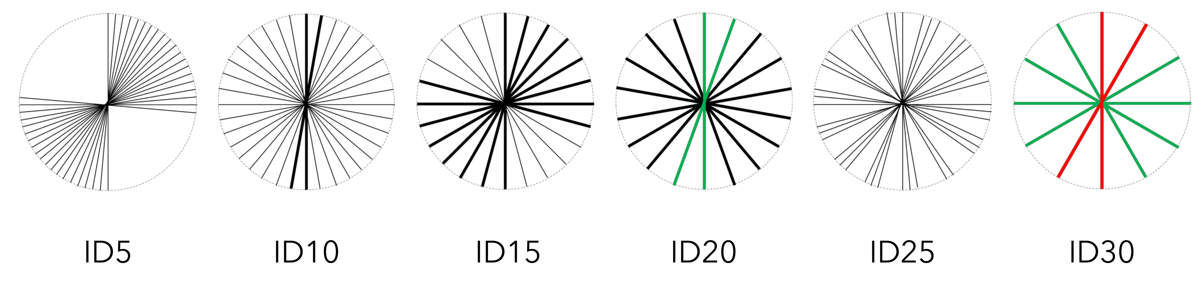
Unidirectional MR70 12P carbon fibre epoxy prepreg supplied from Mitsubishi Chemical Carbon Fiber and Composites and Toray E750 toughened epoxy resin was used to manufacture helicoidal CFRP composites. The unidirectional (UD) plies were stacked using a constant increase in inter-ply pitch angle to form a laminated structure. Six different sample configurations were manufactured for conditioning and testing using the following inter-ply pitch angles in each configuration: 0 (unidirectional, UD), 5 (ID5), 10 (ID10), 15 (ID15), 20 (ID20), 25 (ID25), and 30 (ID30) (Figure 1). In this figure, lines indicate the prepreg stacking angle. Black thin lines indicate a single laminate is present in the composite at a particular stacking angle, a thick black line indicates that two laminates are present in the composite at a particular stacking angle, a thick green line indicates that three laminates are present in the composite at a particular stacking angle, and a thick red line indicates that four laminates are present in the composite at a particular stacking angle. Prepreg UD plies were cut into 300 mm × 300 mm squares and laid up manually. All configurations were manufactured to the same thickness, and due to the pitch angle used for each ply, the finally laminated structures exhibited an asymmetric spiral stacking sequence. This layup allowed for a homogeneous shrinking behaviour during curing, keeping the plates flat. The laminates were cured in a convection oven (Sciquip HT 230), the temperature was raised from ambient temperature to 135 C over one hour, after which it was maintained for another one hour, and then cooled over one hour to room temperature. The specimens were end tabbed using glass fibre/epoxy PCB board laminates manufactured by Farnel with the fibres at to the specimen axis. The tabs were attached to the specimen using prepreg (VTFA 400) and were cured at 110 C for 2 h. Further details are provided for each composite configuration in Table 1.
2.2. Hygrothermal Ageing
All specimens were initially oven-dried at 135 C for 24 h to remove moisture. Composite samples (cf. Table 1) were then immersed into two 140 L tanks of seawater kept at a constant temperature of 40 C and 60 C. Following the ASTM D5229 [23] standard, the water was refreshed at two-week intervals. The seawater was collected from Portobello beach in Scotland, the United Kingdom. Each tank contained 35 coupons, with 5 test coupons per configuration (cf. Table 1). Thirty-five coupons (five from each configuration) were also kept at room temperature conditions as dry, unaged samples. The immersed samples were conditioned alongside four traveller specimens (25 mm by 10 mm) from the UD plates and used for weight measurements and to ascertain the percentage water uptake as a function of immersion time and temperature. An analytical weighing scale was used to weigh the traveller specimens at an accuracy of 0.01 mg.
2.3. Tensile Testing
Manufactured composite laminates were cut using a wet saw into 250 mm by 25 mm coupons in accordance with the ISO 527-4:2009 standard [24]. An MTS Criterion Model 45 with a 333 kN load cell was used to test the specimens, which were clamped at a pressure of 75 bar. The coupons were speckled with white paint so that strain could be recorded using a digital image correlation (DIC) video extensometer (Imetrum) at a frame rate of 17.8 fps. Tensile tests were conducted until the fracture at room temperature and 55% RH, at a cross-head speed of 2 mm/min.
2.4. Finite Element Analysis
Finite element analysis (FEA) was conducted to better understand the behaviour of bioinspired helicoidal composites under a tensile load. The numerical model of each ply of the laminate is described using the in-built Hashin failure model in ABAQUS [25]. It is a widely used failure initiation criterion for FRP laminates and considers failure modes in both fibres and matrix, under both tension and compression [26,27]. The composite models were constructed to mimic the lamination stacking shown in Table 1, and the analyses were performed assuming the specimens were in a dry state. Each laminate model is made up of 20 plies, with different fibre orientations per ply and thus different stacking sequences. Eight-node 24-DoF quadrilateral stress/displacement continuum shell elements (SC8R) were used to discretise composite lay-up formulation. The SC8R elements are general purpose first order interpolation elements with reduced integration. They can be stacked via two-face (faces 4 to 6) contact through the layer thickness, thus enabling layering of the continuum shells, each of which can also be of differential thickness. The change in thickness is computed from element nodal displacements, and these are consecutively computed from a defined effective elastic modulus. They are insensitive to mesh distortion, account for finite membrane strains and arbitrary large rotations, and have hourglass control. The inputs include number of layers, material type and fibre orientation for each layer, and individual layer thickness. Therefore, the following material properties were used in the simulations as per the ABAQUS model layered composite lay-up. Individual carbon fibre reinforced epoxy laminates were given a tensile strength of 1079 MPa, a tensile modulus of 294 GPa, and a Poisson’s ratio of 0.3. The boundary conditions were defined in accordance with the ISO 527-4:2009 standard [24] such that the degree of freedoms of point were fixed at the reaction end of the model, whereas the loading end of the model was statically displaced. Following a mesh sensitivity analysis, optimal meshing was achieved for all models, and 600 elements were generated for every laminate model, with identical element sizes discretising the entire geometry. Since individual lamina within each laminate model were exactly the same size, shared the same boundary conditions, and were of equal thickness, errors from discretisation were controlled and minimised by the use of the same sized and shaped elements. The only variables between each model, therefore, being related to the fibre orientation in the stacking sequence. The boundary conditions were defined in accordance with the ISO 527-4:2009 standard [24] such that all degrees of freedom were fixed at the reaction end of the model, whereas the loading end of the model was statically displaced. Following a mesh sensitivity analysis, optimal meshing was achieved for all models and 600 elements were generated for the laminates, with identical element sizes discretising the whole geometry. Failure is solved for and considers the initiation of failure of the plies under uniaxial loading. Specifically, in this analysis, the 3D Hashin’s failure criterion is considered plane stress. Equations (1)–(4) provide mathematical expressions for different modes of failure, according to Hashin [28].
Equation (1): Fibre tension mode ()
Equation (2): Fibre compression mode ()
Equation (3): Matrix tension mode ()
Equation (4): Matrix compression mode ()
In the above equations, and denote tensile and compressive strengths in the fibre direction, and and denote tensile and compressive strengths in the direction perpendicular to the fibre; and denote the longitudinal and transverse shear strengths; and are normal and shear stresses, respectively. The coefficient relates to the shear stress contribution that causes fibre failure initiation in the tensile mode.
3. Results and Discussion
3.1. Water Absorption
After several intervals, the percentage water absorption characteristics of the composites were calculated by the relative intake of weight defined by according to Equation (5), where is the moisture uptake at time t, is the weight at time t, and is the original weight of the specimen prior to immersion.
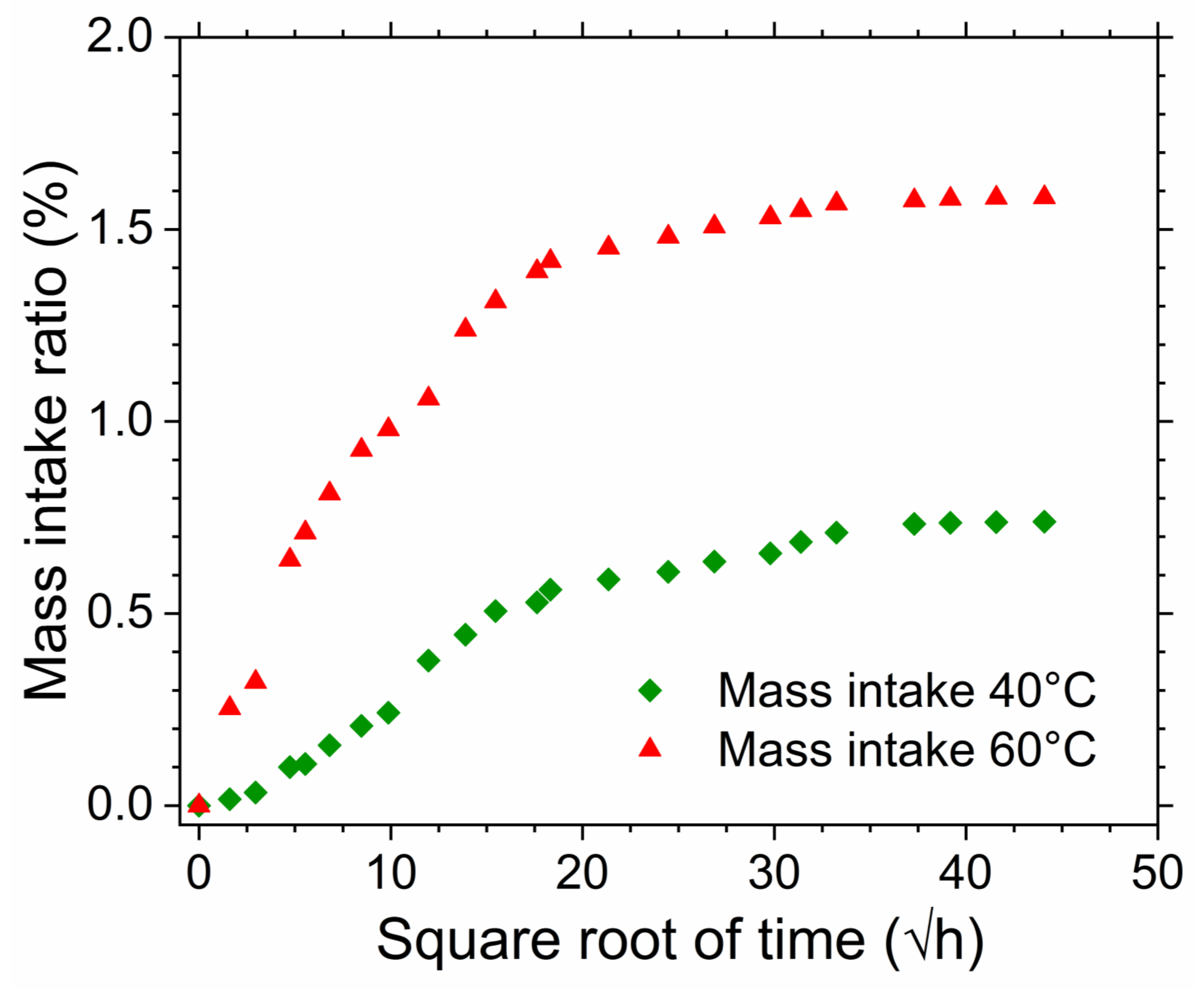
Figure 2 shows the percentage of water absorption of UD composite travellers during the process of hygrothermal ageing at 40 C and 60 C, as a function of the square root of time. Unidirectional samples were chosen for comparative purposes with information available in the literature. Samples conditioned at 60 C reached saturation within fifteen days, whereas samples conditioned at 40 C reached saturation after two months of immersion. The absorption curve shows that the water absorption rate at the initial stages of immersion is much higher in specimens conditioned at 60 C than in those conditioned at 40 C. This is due to the higher temperature at which the process takes place. The higher energy potential enables a a faster rate of water diffusion into the free volumes of the polymeric matrix. Water also has hydrogen bonds, which plasticise the polymer matrix and are partly responsible for the matrix swelling [16], which in turn can exacerbate the rate of water diffusion [29]. This in part explains how the saturation levels are different as a function of the hygrothermal ageing temperature, 0.74% at 40 C and 1.59% at 60 C. The absorption curves further reveal that at the early stages of the immersion, the diffusion rate of water into the composite samples was highest and that this rate slows down as it approaches saturation. This Fickian diffusion behaviour [19] is common in hygrothermally aged FRP composites [30]. The equilibrium water uptake, Equation (6), and diffusion coefficient, Equation (8), are shown in Table 2 at each hygrothermal ageing temperature. When the ageing temperature is increased from 40 C to 60 C, the diffusion coefficient, calculated by Equation (7), increased from 4.287 to 6.268 m s. The same trend was observed for saturation level of water uptake.
According to Soles et al. [30], the diffusion coefficient, D, which is an essential parameter in Fick’s law, is calculated using Fick’s second law of diffusion, Equation (6), where is the equilibrium moisture uptake, and h is the thickness of the composite samples. The equation can then be rearranged for D, Equation (7).
3.2. Tensile Properties
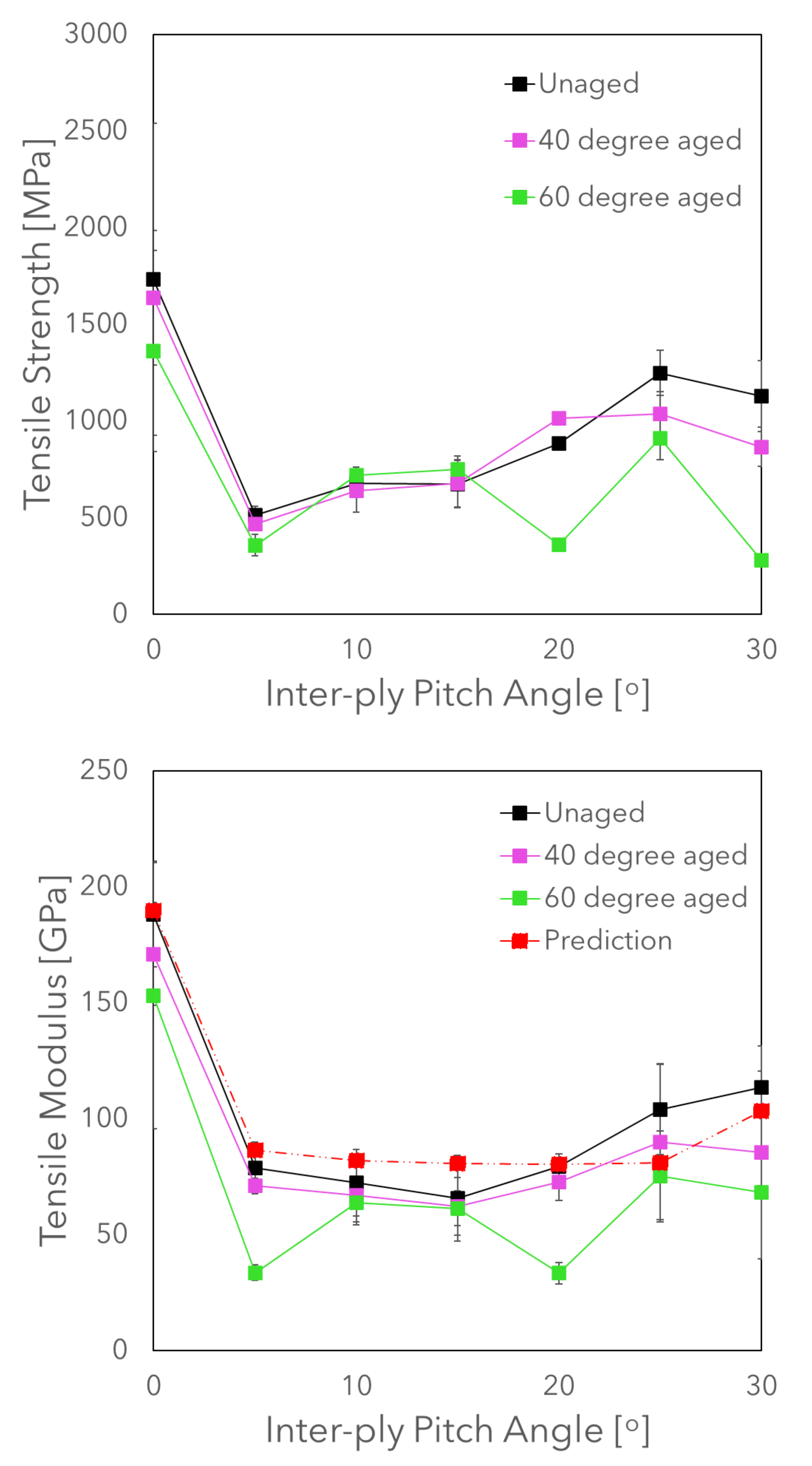
Figure 3 shows the influence of hygrothermal ageing on the tensile strength and tensile modulus of the samples tested. The graph shows these properties plotted against the inter-ply pitch angle, and a non-linear relationship is observed for both properties as a function of the inter-ply pitch angle. A predictive model for the Young’s modulus was derived using a mixtures rule modified to account for the changing angles based on laminate theory, and these were compared against the experimental results, as shown in Equation (8), where is the composite Young’s modulus, is the Young’s modulus of the fibre, is the Young’s modulus of the matrix, is the volume fraction of the fibre, is the volume fraction of matrix, is the fibre orientation angle in each individual laminate, a, b, and c are constants, and is for all plies. The mean fibre to matrix volume fraction ratio was measured as 51%:49% and used in Equation (8). Here, as only the unaged fibre and matrix properties were known, the model predictions were compared against unaged samples, and these lie within one standard deviation of the mean values of each of the experimental samples. The tensile modulus is therefore a second order function of the inter-ply pitch angle when calculated within a mixtures rule but is only evidenced for inter-ply pitch angles between 0–30. This second order relationship appears to remain for composites aged at 40 C, but becomes less obvious after ageing at 60 C, indicating that the 60 C ageing process damages the microstructure of the composites with different inter-ply pitch angles in an inhomogeneous manner, meaning that the tensile modulus values of hygrothermally aged asymmetric helicoidal composites are significantly harder to predict than for unaged equivalents.
The moisture uptake coupled to ageing temperature has a mild effect on the tensile properties of the different composite samples. Strength is plotted in Figure 3 against the inter-ply pitch angle for each of the composite structures. Of all the composites, taking into account the magnitude of the standard deviation error bars, the strength of UD composites (with an inter-ply pitch angle of 0) is most significantly affected by the process of hygrothermal ageing. This is because UD composites have a fibre dominated mechanical strength with a strong dependence on the interfacial strengths between fibre and matrix. Once this interface is weakened, the stress transfer capacity from the fibres to the matrix is reduced and the composites are more likely to experience failure at lower levels of stress. Much lower overall strengths were observed in helicoidal structures with inter-ply pitch angles , and the change in strength properties indicate a transition from fibre interface dominated failure to matrix dominated failure. In samples where there were more laminates with orientation angles closer to the axis of loading, the strengths were higher, but the drop in strength from hygrothermal ageing was also more significant, 5.4% and 21.4% for hygrothermally aged samples at 40 C and 60 C, respectively. We further propose that in samples where the strengths were low, and the drop in strength was low, that these were primarily matrix dominated failure strengths (fewer laminates oriented towards the loading axis), which rely less on the interfacial properties between fibre and matrix and more on the bulk properties of the weaker material, the matrix.
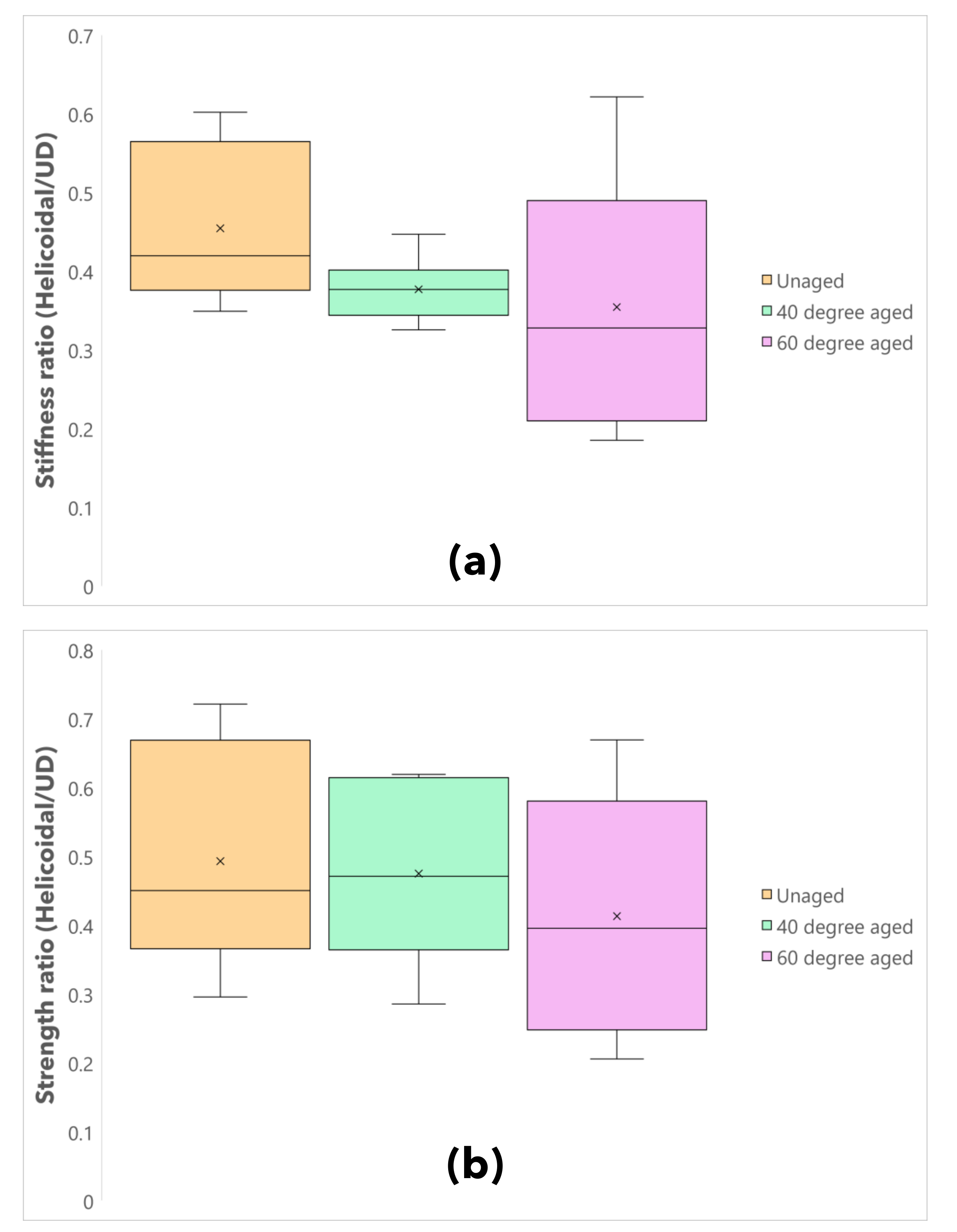
It can be useful to normalise the properties of helicoidal composites to better understand how ageing affects their strength and stiffness properties. Figure 4 provides box and whisker diagrams of samples normalised for (a) the stiffness and (b) the strength of helicoidal composites against UD composites for each of the unaged, 40 C hygrothermally aged, and 60 C hygrothermally aged sample sets. Here, the stiffness ratio is calculated as and the strength ratio is calculated as , where is the mean Young’s modulus of a helicoidal composite, is the mean Young’s modulus of the unidirectional composite, is the mean strength of a helicoidal composite, and is the mean strength of the unidirectional composite. The mean strength and stiffness ratios are observed to decease under higher ageing temperatures, indicating that this increase in ageing temperature on average reduces the strength and stiffness properties of helicoidal composites as compared to their UD equivalents under the same conditions. The inter-quartile stiffness ratio ranges of the unaged and 60 C hygrothermally aged samples are more than triple that of the 40 C samples, indicating that less variability in the results was observed for the 40 C samples than for samples under any other condition. The strength ratio inter-quartile range of 40 C samples is nevertheless significantly higher than for its equivalent stiffness ratio, and this range is closer to that observed for the unaged and 60 C aged samples. This said, it is still lower than for the 60 C composites. These results indicate that in general, ageing at 40 C reduces the variability of the stiffness and strength ratios of helicoidal composites as compared to UD composites under similar conditions, whereas ageing at 60 C increases the variability of the stiffness and strength ratios of helicoidal composites as compared to UD composites under similar conditions.
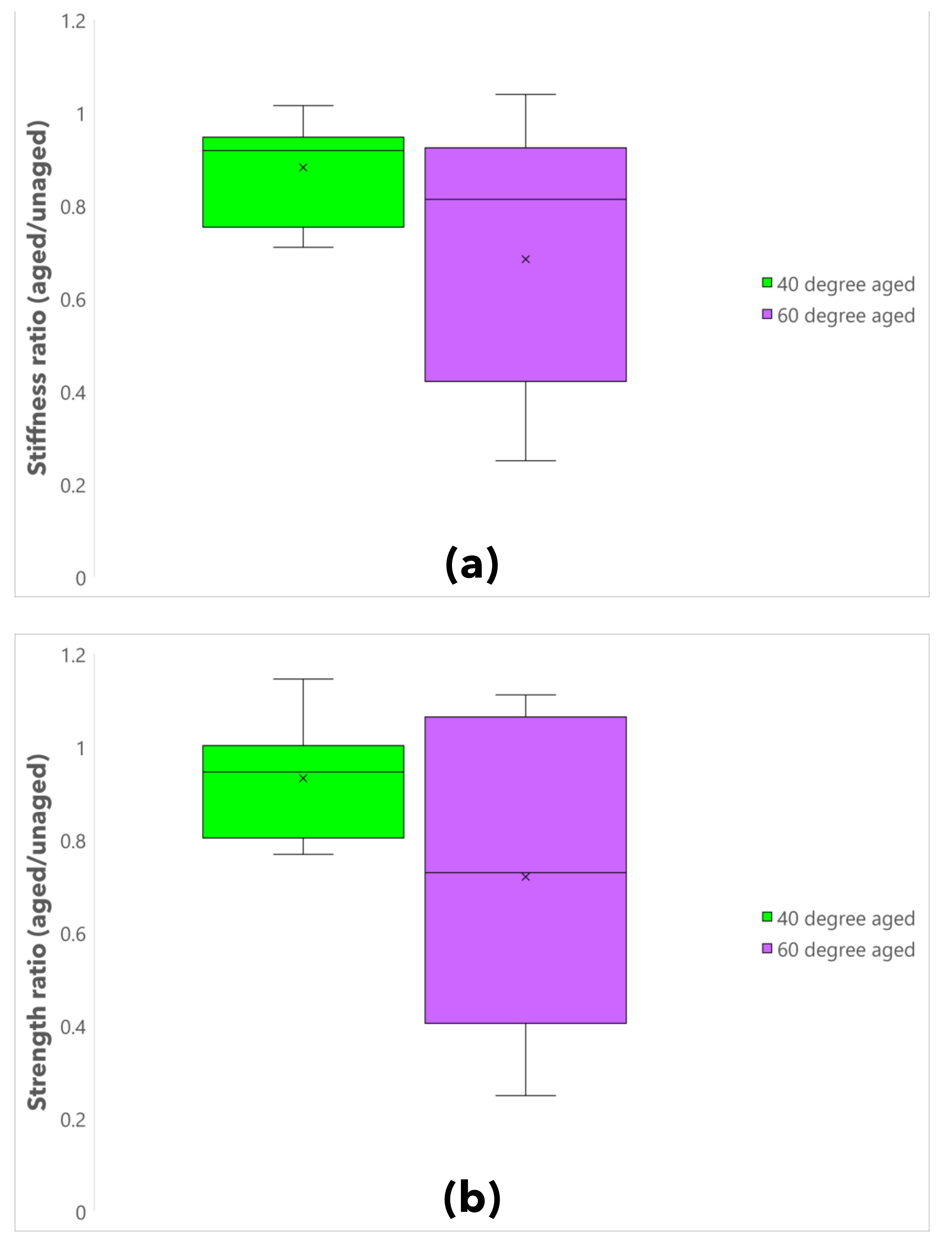
Figure 5 provides box and whisker diagrams of samples normalised for (a) the stiffness and (b) the strength of hygrothermally aged composites normalised against their unaged equivalents. Here the stiffness ratio is calculated as and the strength ratio is calculated as , where is the Young’s modulus of hygrothermally aged composites (at either 40 C or 60 C) within their specific sample set, is the Young’s modulus of unaged composites within the same sample set, is the strength of hygrothermally aged composites (at either 40 C or 60 C) within their specific sample set, and is the strength of unaged composites within the same sample set. Both the mean and median values of 60 C aged samples are lower than those of 40 C aged samples, indicating that, on average, this increase in ageing temperature causes a reduction in the strength and stiffness of both UD and helicoidal composites as compared to their unaged equivalents. The stiffness and strength ratio inter-quartile ranges are higher for 60 C aged composites than for 40 C composites, indicating that ageing gives rise to greater variability in the mechanical properties of the same composites.
3.3. Failure Modes
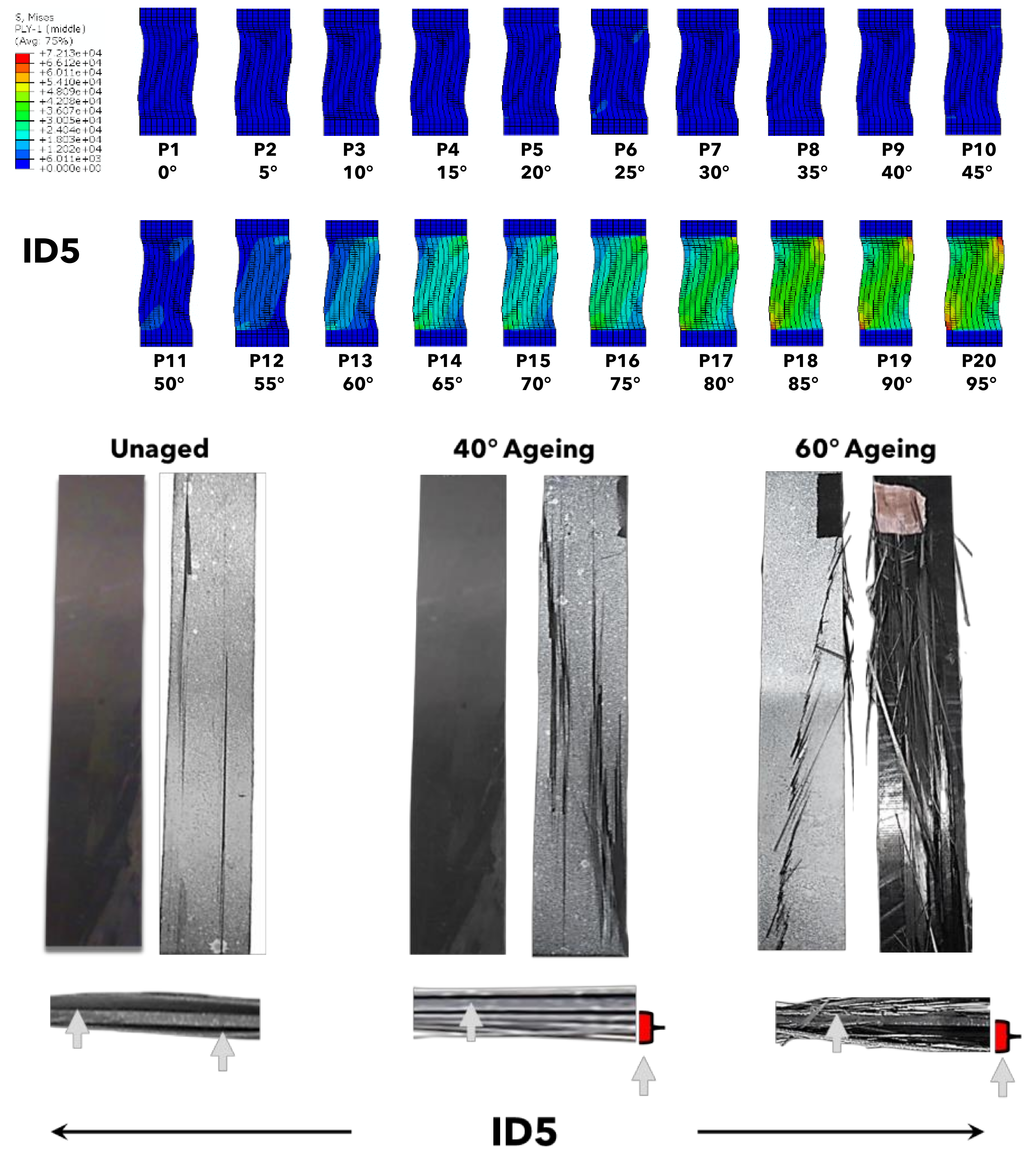
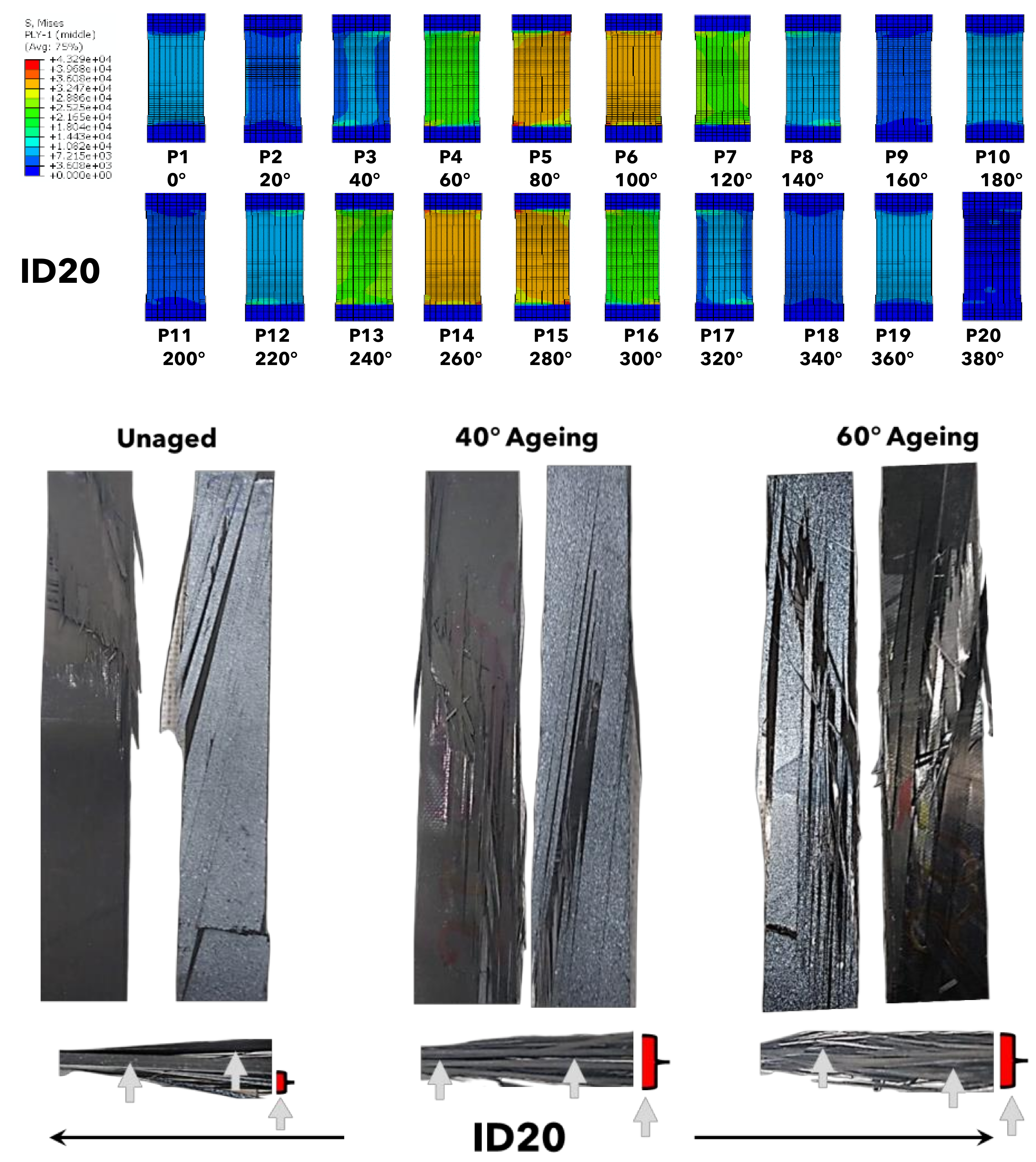
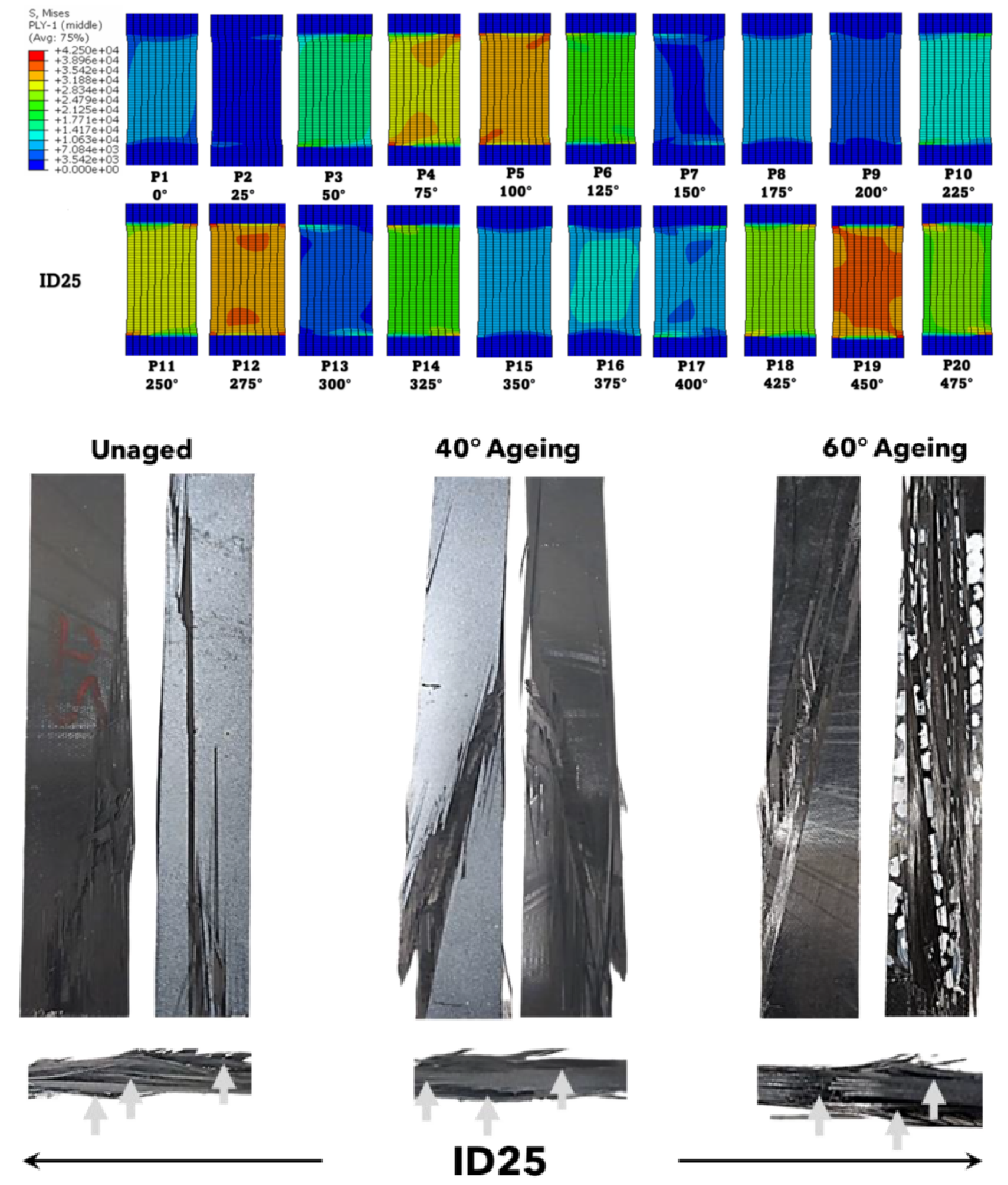
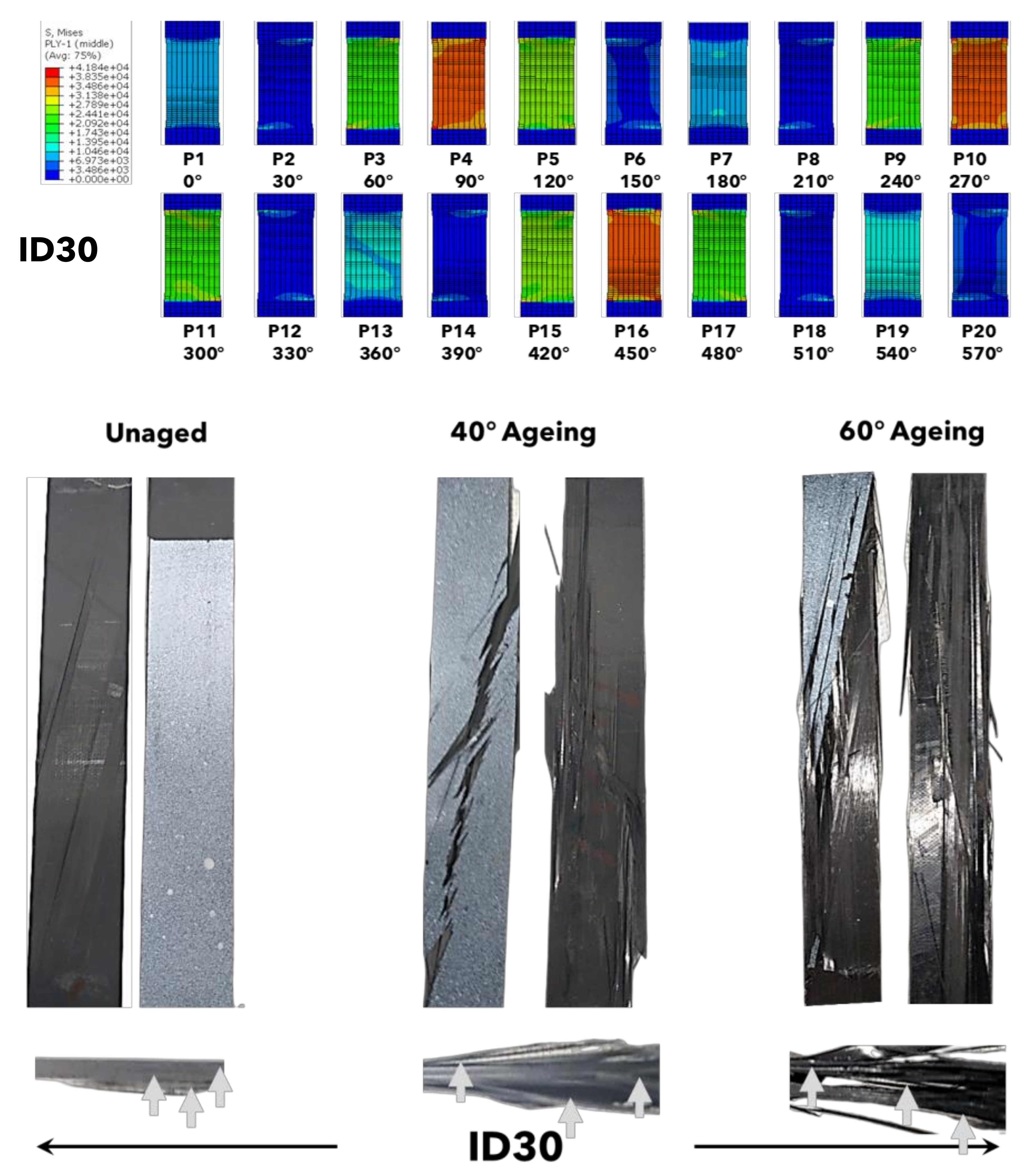
Figure 6, Figure 7, Figure 8, Figure 9, Figure 10 and Figure 11 show the ply-by-ply stress (von Mises) distributions in individual dry plies predicted using the Hashin failure model for each of the composites (ID5-30) as well as representative fractured samples from each of the different sample sets as dry, hygrothermally aged at 40 C, and hygrothermally aged at 60 C. All samples failed in an explosive manner; however, whereas fracture was more localised in dry samples, samples aged at 40 C and 60 C showed significant more splaying of fibres, with splaying being greatest in 60 C aged samples and lowest in dry samples. As described by Meng et al. [13] and Alam et al. [14], both moisture content and temperature leads to a degradation of the mechanical properties of CFRP composites. Temperature increases water uptake (cf. Figure 2), and as such, there can be both greater plasticisation of the matrix in addition to higher levels of water diffusion to fibre-matrix interfaces. As a consequence of fibre-matrix bond degradation from hygrothermal ageing, energy stored and then released in hygrothermally aged composites will result in higher levels of fibre-matrix failure and thence, fibre splaying, as seen in every sample set (ID5-30). Hygrothermal ageing also appears to increase in-plane (mode III) fibre twisting in certain composite samples at certain orientation angles. This is presumably a result of matrix plasticisation, which softens the attached matrix, enabling higher levels of deformation and hence, fibre rotation under similar levels of loading. Although observations and comments can only be made on surface laminates, the ability for fibres to rotate within a ply is likely also influenced by adjacent attached laminates, the extent to which the adjacent laminates rotate under load, and the way in which adjacent laminates and their deformation constrain the rotation of adjacent laminates. Evidence of fibre rotation within surface laminates can be most prominently seen in ID5 at 60 C ageing (left side), where fractured fibres visibly change angle from one end of the fracture line to the other; ID15 at 60 C (right hand side) (left and right hand sides), where the angle of failure is higher in the aged sample than in the dry sample; ID20 at both 40 C and 60 C (left hand side), where the failure angles in the aged samples are almost double that of the dry sample, similarly to ID25 (left and right hand sides), where the fracture angle in both 40 C and 60 C aged samples is greater than that of the dry sample; and ID30 at 40 C (left hand side), where the fracture angle similarly to ID5 changes continually in the same direction along the length of the crack.
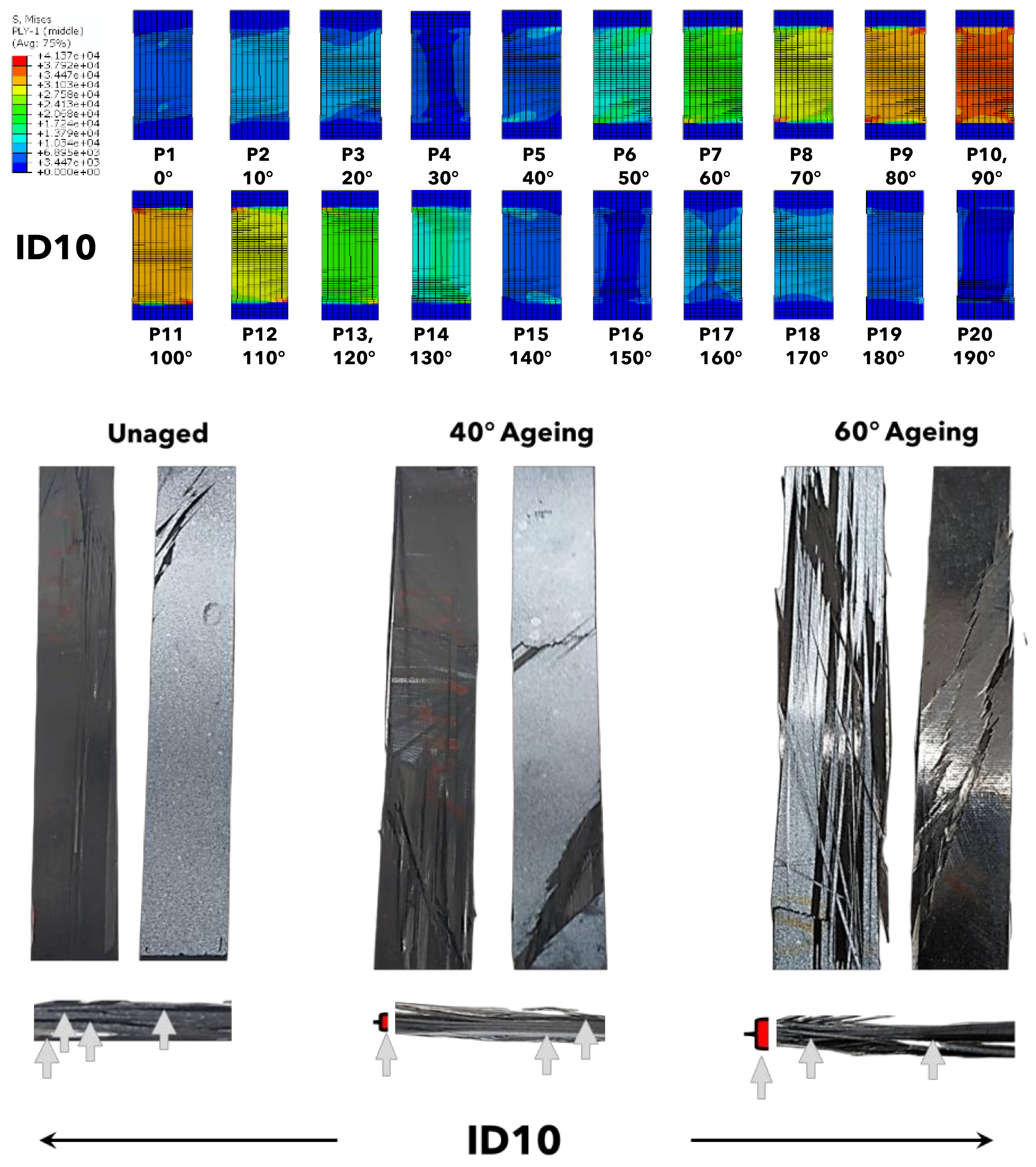
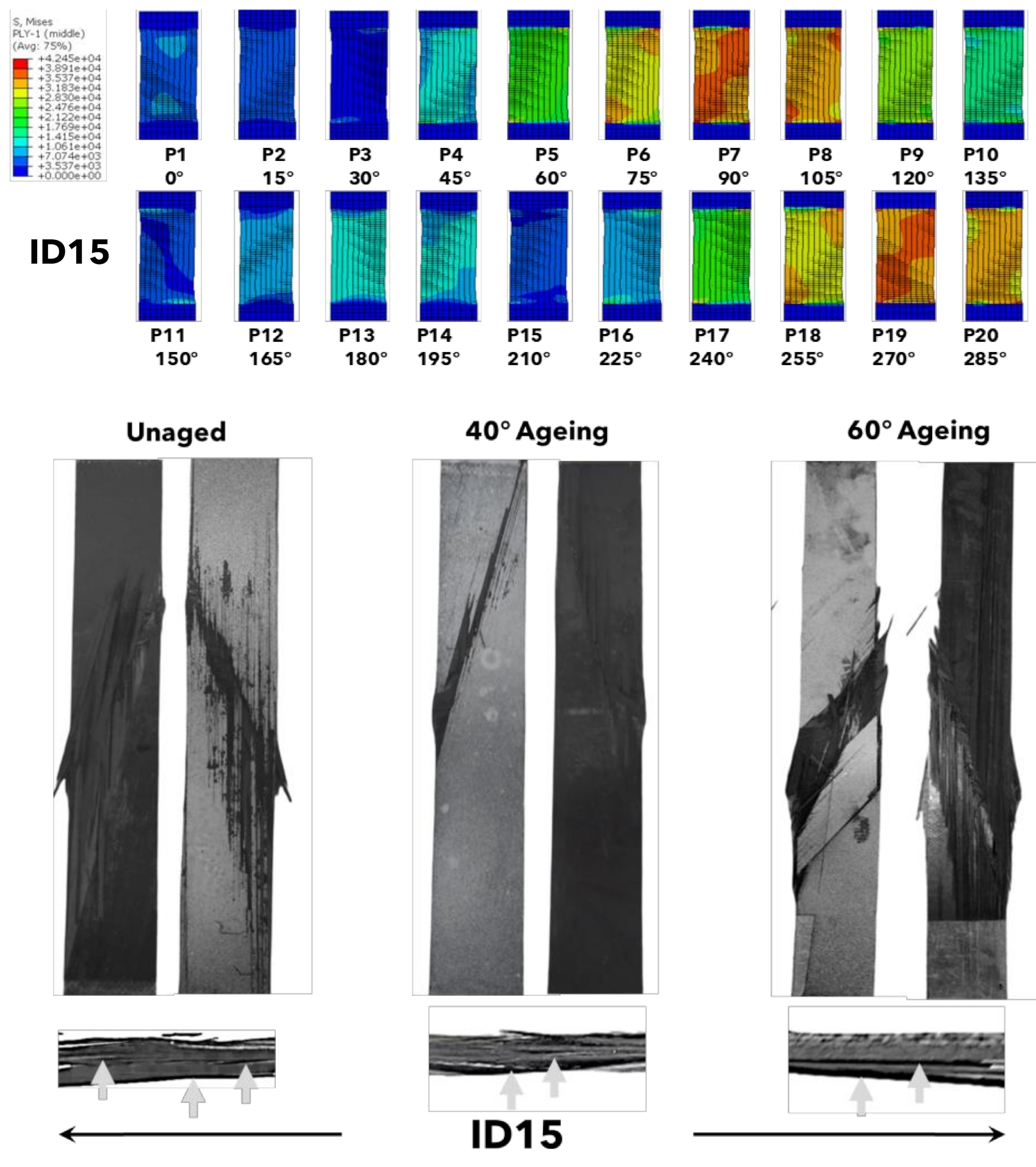
When observing the stress (von Mises) distributions in individual dry plies predicted using the Hashin failure model, noticeably higher levels of failure are observed where laminate orientations have inter-ply pitch angles closer to 90 from the axis of loading than those that are closer to 0 relative to the direction of loading. These laminates could be considered plies where composite failure initiates, and this prediction is by-and-large acceptable when the simulation results are compared against side view fracture profiles, identifying the main (more prominent) fracture lines in the cross sections. In ID5 for example, failure is expected to be most prominent in the lower plies (plies 13–20) with some failure build up in ply 6, and this is observed most prominently in samples aged at 40 C and 60 C, but can also be seen as more localised fracture in the dry sample. The failure predictions for ID10 are primarily in the central plies (6–14) but with continued lesser failure to the outer plies, and this is reflected in the main fracture paths observed from a side view, with the fractures lines being most noticeable in the aged samples. Failure in ID15, predicted to occur at the central and bottom face plies (plies 5–8 and 17–20), can also be seen in the side view profiles, more notably in the dry and 40 C aged samples, and only bottom face ply failure observed in 60 C aged samples. ID20 is similar to ID 10 in that failure is expected to evolve extra-centrally (plies 5–6 and 14–15) with slightly lower levels of failure evolving in adjacent central plies and plies leading to the top and bottom faces. This is observed in the side view fracture images, with complete splaying of fibres in the aged samples making it harder to see specific lines of weakness in the composite. Fracture paths observed from the side view of ID25 samples also correlate with the Hashin failure predictions with fracture expected (and seen) to be primarily extra-central (plies 4–5 and 11–12) and at the bottom face (ply 19). Failure in ID25 is also predicted to be relatively high in all other plies in this composite, and several smaller fracture lines are observable in other plies in the sample. Failure in ID30 is predicted to occur both centrally (ply 10) and extra-centrally (plies 4 and 16), and this is observed in fracture profiles with fibre splaying in these samples, making the weak plies in this sample set easier to identify.
4. Conclusions
Assymetric helicoidally stacked Toray E750 carbon fibre reinforced toughened epoxy resin composites were researched with an aim to determine both their properties and failure modes under tensile loading in unaged and hygrothermally aged conditions. A mixtures model modified to incorporate the effect of laminate stacking angle was shown to be a good analytical method for predicting tensile modulus, with all values lying within one standard deviation of the arithmetic mean of unaged tested sample sets. Composites aged at 60 absorb significantly higher fractions of water as compared to 40 aged composites (D increased from 4.287 to 6.268 m s from 40 to 60) and show clear losses in either strength or stiffness as a result. Nevertheless, UD composites lose more of their original strength and stiffness from ageing than the helicoidal composites. Higher hygrothermal ageing temperatures not only decrease the stiffness and strength ratios of asymmetric helicoidal composites as compared to UD composites subjected to the same conditioning, but also decrease the strength and stiffness ratios of all composites as compared to their unaged equivalents. Increased water absorption also affects the fracture behaviour of asymmetric helicoidal composites, with the higher levels of fibre splaying observed most likely related to degradation of fibre-matrix interfaces. Water absorption also gives rise to higher levels of in-plane mode III laminate twisting, presumably because plasticity in the matrix enables greater mobility of fibres. The Hashin failure model predicts failure in certain laminates, which are likely failure initiation laminates. These predictions were qualitatively evidenced by comparing against primary fracture paths observed in mechanically tested composites.
Author Contributions
Conceptualization, P.A.; methodology, C.R., C.N. and P.A.; software, C.N.; validation, P.A.; formal analysis, P.A. and C.N.; investigation, C.N., C.R. and P.A.; resources, P.A.; data curation, P.A. and C.N.; writing—original draft preparation, C.N. and P.A.; writing—review and editing, P.A.; visualization, P.A.; supervision, P.A.; project administration, P.A.; funding acquisition, C.N. All authors have read and agreed to the published version of the manuscript.
Funding
This research was funded by the Territory Education Trust Fund (TETFund) Nigeria.
Institutional Review Board Statement
Not applicable.
Informed Consent Statement
Not applicable.
Data Availability Statement
All data are available from the corresponding author on request.
Acknowledgments
We would like to thank the Territory Education Trust Fund (TETFund) Nigeria for providing a PhD scholarship awarded to Chidume Nnamdi Nwambu that has made this work possible.
Conflicts of Interest
The authors declare no conflict of interest.
References
- Wegst, U.G.; Bai, H.; Saiz, E.; Tomsia, A.P.; Ritchie, R.O. Bioinspired structural materials. Nat. Mater. 2015, 14, 23–36. [Google Scholar] [CrossRef] [PubMed]
- Suksangpanya, N.; Yaraghi, N.A.; Kisailus, D.; Zavattieri, P. Twisting cracks in Bouligand structures. J. Mech. Behav. Biomed. Mater. 2017, 76, 38–57. [Google Scholar] [CrossRef] [PubMed]
- Alam, P. Structures and Composition of the Crab Carapace: An Archetypal Material in Biomimetic Mechanical Design. In Marine Organisms as Model Systems in Biology and Medicine. Results and Problems in Cell Differentiation; Kloc, M., Kubiak, J., Eds.; Springer: Cham, Switzerland, 2018; Volume 65. [Google Scholar]
- Pinto, F.; Lervolino, O.; Scarselli, G.; Ginzburg, D.; Meo, M. Bioinspired twisted composites based on Bouligand structures. In Bioinspiration, Biomimetics and Bioreplication, Proceedings of the SPIE, Materials and Processing; Las Vegas, NV, USA, 20–24 March 2016, SPIE: Bellingham, WA, USA, 2016. [Google Scholar]
- Wang, H.; Zhou, W.; Gui, L.; Ji, H.; Zhang, X. Analysis of effect of fibre orientation on Young’s modulus for unidirectional fibre reinforced composites. Compos. Part B 2014, 56, 733–739. [Google Scholar] [CrossRef]
- Sayekti, P.R.; Fahrunnida; Cerniauskas, G.; Robert, C.; Retnoaji, B.; Alam, P. The Impact Behaviour of Crab Carapaces in Relation to Morphology. Materials 2020, 13, 3994. [Google Scholar] [CrossRef] [PubMed]
- Apichattrabrut, T.; Ravi-Chander, K. Helicoidal Composites. Mech. Adv. Mater. Struct. 2006, 13, 61–76. [Google Scholar] [CrossRef]
- Shah, S.Z.H.; Karuppanan, S.; Megat-Yusoff, P.S.M.; Sajid, Z. Impact resistance and damage tolerance of fiber reinforced composites: A review. Compos. Struct. 2019, 217, 100–121. [Google Scholar] [CrossRef]
- Mencatelli, L.; Pinho, S.T. Ultra-thin-ply CFRP Bouligand bio-inspired structures with enhanced load-bearing capacity, delayed catastrophic failure and high energy dissipation capability. Compos. Part A Appl. Sci. Manuf. 2020, 129, 105655. [Google Scholar] [CrossRef]
- Chinta, V.S.; Raj, S.S.; Reddy, P.R.; Vincent, E. Numerical and experimental investigation of effect of stacking sequence on the fracture parameters of composite materials. J. Xi’an Univ. Archit. Technol. 2021, 2, 1006–7930. [Google Scholar]
- Camanho, P.P.; Catalanotti, G. On the relation between the mode I fracture toughness of a composite laminate and that of a 0° ply: Analytical model and experimental validation. Eng. Fract. Mech. 2011, 78, 2535. [Google Scholar] [CrossRef]
- Kaman, M.O. Effect of fiber orientation on fracture toughness of laminated composite plates [0°/θ°]s. Eng. Fract. Mech. 2011, 78, 2521. [Google Scholar] [CrossRef]
- Meng, M.; Rizvi, J.; Grove, S.; Le, H. Effects of hygrothermal stress on the failure of CFRP composites. Compos. Struct. 2015, 133, 1024–1035. [Google Scholar] [CrossRef] [Green Version]
- Alam, P.; Robert, C.; Bradaigh, C.M.O. Tidal turbine blade composites—A review on the effects of hygrothermal aging on the properties of CFRP. Compos. Part B Eng. 2018, 149, 248–259. [Google Scholar] [CrossRef]
- Davies, P. Environmental degradation of composites for marine structures: New materials and new applications. Philos. Trans. R. Soc. A 2016, 374, 20150272. [Google Scholar] [CrossRef] [PubMed]
- Feih, S.; Boiocchi, E.; Kandare, E.; Mathys, Z.; Gibson, A.; Mouritz, A. Strength degradation of glass and carbon fibres under high temperature. In Proceedings of the International Committee on Composite Materials, Edinburgh, UK, 27–31 July 2009. [Google Scholar]
- Zafar, A. Investigation of the long term effects of moisture on carbon fibre and epoxy matrix composites. Compos. Sci. Technol. 2012, 72, 656–666. [Google Scholar] [CrossRef]
- Arhant, M.; Gac, P.; Gall, M.; Burtin, C.; Criancon, C.; Davies, P. Effects of sea water and humidity on the tensile and compressive properties of carbon-polyamide 6 laminates. Compos. Part A 2016, 91, 250–261. [Google Scholar] [CrossRef] [Green Version]
- Bond, D. Moisture diffusion in a fibre-reinforced composite: Part I non-Fickian transport and the effect of fibre spatial distribution. J. Compos. Mater. 2005, 39, 2113–2141. [Google Scholar] [CrossRef]
- Cairns, D.; Adams, D. Moisture and thermal expansion properties of unidirectional composite materials and the epoxy matrix. J. Reinf. Plast. Compos. 1984, 2, 300–316. [Google Scholar] [CrossRef]
- Selzer, R.; Fredrich, K. Mechanical properties and failure behaviour of carbon fibre-reinforced polymer composites under the influence of moisture. Compos. Part A 1997, 28, 595–604. [Google Scholar] [CrossRef]
- Zhou, J.; Lucas, J. Hygrothermal effects of polymer resin. Part I: The nature of water in epoxy. Polymer 1999, 40, 5505–5512. [Google Scholar] [CrossRef]
- ASTM. A Standard Test Method for Moisture Absorption Properties and Equilibrium Conditioning of Polymer Matrix Composite Materials; ASTM International: West Conshohocken, PA, USA, 2004; Volume 13. [Google Scholar]
- BS-EN-ISO-527-5; Plastics–Determination of Tensile Properties Part 5: Test Conditions for Unidirectional Fibre-Reinforced Plastic Composites. European Committee for Standardisation: Brussels, Belgium, 2009.
- Hashin, Z. Fatigue failure criteria for unidirectional fibre composites. J. Appl. Mech. Trans. ASME 1981, 48, 846–852. [Google Scholar] [CrossRef]
- Talreja, R. Assessment of the fundamentals of failure theories for composite materials. Compos. Sci. Technol. 2014, 105, 190–201. [Google Scholar] [CrossRef]
- Rozylo, P.; Falkowicz, K.; Wysmulski, P.; Debski, H.; Pasnik, J.; Kral, J. Experimental-Numerical Failure Analysis of Thin-Walled Composite Columns Using Advanced Damage Models. Materials 2022, 15, 167. [Google Scholar] [CrossRef] [PubMed]
- Alam, P. Composites Engineering: An A-Z Guide; IOP Press: Bristol, UK, 2021. [Google Scholar]
- Wang, Y.; Hahn, T. AFM characterisation of the interfacial properties of carbon fibre reinforced polymer composites subjected to hygrothermal treatments. Compos. Sci. Technol. 2007, 67, 92–101. [Google Scholar] [CrossRef]
- Soles, C.; Chang, F.; Gidley, W.; Yee, A. Contributions of the nanovoid structure to the kinetics of moisture transport in epoxy resins. J. Polym. Sci. Part B 2000, 38, 776–791. [Google Scholar] [CrossRef]
Figure 1.
Pictorial representation of the laminate stacking sequences. Here, lines indicate the prepreg stacking angle. Black thin lines indicate a single laminate is present in the composite at a particular stacking angle, a thick black line indicates that two laminates are present in the composite at a particular stacking angle, a thick green line indicates that three laminates are present in the composite at a particular stacking angle, and a thick red line indicates that four laminates are present in the composite at a particular stacking angle.

Figure 2.
Moisture absorption of composite travellers (UD) immersed in 40 C and 60 C seawater.

Figure 3.
Mean values of tensile strength and tensile modulus, for all sample sets ( for each sample set), plotted as a function of the inter-ply pitch angle. Standard deviations about the mean are shown by y-error bars.
Figure 3.
Mean values of tensile strength and tensile modulus, for all sample sets ( for each sample set), plotted as a function of the inter-ply pitch angle. Standard deviations about the mean are shown by y-error bars.

Figure 4.
Box and whisker plot of (a) the stiffness ratio and (b) the strength ratio of helicoidal composites to UD composites subjected to the same conditioning: unaged, 40 C ageing, and 60 C ageing.
Figure 4.
Box and whisker plot of (a) the stiffness ratio and (b) the strength ratio of helicoidal composites to UD composites subjected to the same conditioning: unaged, 40 C ageing, and 60 C ageing.

Figure 5.
Box and whisker plot of (a) the stiffness ratio and (b) the strength ratio of composite groups at 40 C ageing and 60 C ageing to their unaged equivalents.
Figure 5.
Box and whisker plot of (a) the stiffness ratio and (b) the strength ratio of composite groups at 40 C ageing and 60 C ageing to their unaged equivalents.

Figure 6.
Stress (von Mises) distributions in individual dry plies predicted using the Hashin failure model, for ID5 composites (top), front and back face fractures from representative dry, 40 C, and 60 C aged samples (middle), and side view fractures from representative dry, 40 C, and 60 C aged samples (bottom), with arrows indicating the primary areas of fracture identified.

Figure 7.
Stress (von Mises) distributions in individual dry plies predicted using the Hashin failure model, for ID10 composites (top), front and back face fractures from representative dry, 40 C, and 60 C aged samples (middle), and side view fractures from representative dry, 40 C, and 60 C aged samples (bottom), with arrows indicating the primary areas of fracture identified.

Figure 8.
Stress (von Mises) distributions in individual dry plies predicted using the Hashin failure model, for ID15 composites (top), front and back face fractures from representative dry, 40 C, and 60 C aged samples (middle), and side view fractures from representative dry, 40 C, and 60 C aged samples (bottom), with arrows indicating the primary areas of fracture identified.

Figure 9.
Stress (von Mises) distributions in individual dry plies predicted using the Hashin failure model, for ID20 composites (top), front and back face fractures from representative dry, 40 C, and 60 C aged samples (middle), and side view fractures from representative dry, 40 C, and 60 C aged samples (bottom), with arrows indicating the primary areas of fracture identified.

Figure 10.
Stress (von Mises) distributions in individual dry plies predicted using the Hashin failure model, for ID25 composites (top), front and back face fractures from representative dry, 40 C, and 60 C aged samples (middle), and side view fractures from representative dry, 40 C, and 60 C aged samples (bottom), with arrows indicating the primary areas of fracture identified.

Figure 11.
Stress (von Mises) distributions in individual dry plies predicted using the Hashin failure model, for ID30 composites (top), front and back face fractures from representative dry, 40 C, and 60 C aged samples (middle), and side view fractures from representative dry, 40 C, and 60 C aged samples (bottom), with arrows indicating the primary areas of fracture identified.


Table 1.
Laminate stacking sequences for composite sample sets arranged at specific inter-ply pitch angles.
Table 1.
Laminate stacking sequences for composite sample sets arranged at specific inter-ply pitch angles.
| Inter-ply Pitch Angle | ID | Stacking Sequence | No. Samples | Thickness (mm) | No. Plies |
|---|---|---|---|---|---|
| 0 | UD | [0/0/0/0/0/…/0] | 15 | 1.9 | 20 |
| 5 | ID5 | [0/5/10/15/20/…/95] | 15 | 1.9 | 20 |
| 10 | ID10 | [0/10/20/30/40/…/190] | 15 | 1.9 | 20 |
| 15 | ID15 | [0/15/30/45/60/…/285] | 15 | 1.9 | 20 |
| 20 | ID20 | [0/20/40/60/80/…/380] | 15 | 1.9 | 20 |
| 25 | ID25 | [0/25/50/75/100/…/475] | 15 | 1.9 | 20 |
| 30 | ID30 | [0/30/60/90/120/…/570] | 15 | 1.9 | 20 |
Table 2.
Equilibrium water uptake, , and diffusion coefficient, D, at the two hygrothermal ageing temperatures used in this study.
Table 2.
Equilibrium water uptake, , and diffusion coefficient, D, at the two hygrothermal ageing temperatures used in this study.
| Temperature (C) | D m s | |
|---|---|---|
| 40 | 0.73 | 4.287 |
| 60 | 1.58 | 6.268 |
Publisher’s Note: MDPI stays neutral with regard to jurisdictional claims in published maps and institutional affiliations. |
© 2022 by the authors. Licensee MDPI, Basel, Switzerland. This article is an open access article distributed under the terms and conditions of the Creative Commons Attribution (CC BY) license (https://creativecommons.org/licenses/by/4.0/).
Share and Cite
MDPI and ACS Style
Nwambu, C.; Robert, C.; Alam, P. The Tensile Behaviour of Unaged and Hygrothermally Aged Asymmetric Helicoidally Stacked CFRP Composites. J. Compos. Sci. 2022, 6, 137. https://0-doi-org.brum.beds.ac.uk/10.3390/jcs6050137
AMA Style
Nwambu C, Robert C, Alam P. The Tensile Behaviour of Unaged and Hygrothermally Aged Asymmetric Helicoidally Stacked CFRP Composites. Journal of Composites Science. 2022; 6(5):137. https://0-doi-org.brum.beds.ac.uk/10.3390/jcs6050137
Chicago/Turabian StyleNwambu, Chidume, Colin Robert, and Parvez Alam. 2022. "The Tensile Behaviour of Unaged and Hygrothermally Aged Asymmetric Helicoidally Stacked CFRP Composites" Journal of Composites Science 6, no. 5: 137. https://0-doi-org.brum.beds.ac.uk/10.3390/jcs6050137