Review

Failures and Flaws in Fused Deposition Modeling (FDM) Additively Manufactured Polymers and Composites

1
Laboratory for Advanced NonDestructive Testing, In-Situ Monitoring and Evaluation (LANDTIE), Department of Manufacturing Engineering, Georgia Southern University, Statesboro, GA 30458, USA
2
Department of Chemistry and Biochemistry, Georgia Southern University, Statesboro, GA 30458, USA
3
Department of Mathematics and Statistics, South Dakota University, Bookings, SD 57007, USA
*
Author to whom correspondence should be addressed.
J. Compos. Sci. 2022, 6(7), 202; https://0-doi-org.brum.beds.ac.uk/10.3390/jcs6070202
Submission received: 26 May 2022 / Revised: 2 July 2022 / Accepted: 6 July 2022 / Published: 8 July 2022
(This article belongs to the Special Issue Characterization and Modelling of Composites, Volume II)

Abstract

:
In this review, the potential failures and flaws associated with fused deposition modeling (FDM) or fused filament fabrication (FFF) 3D printing technology are highlighted. The focus of this article is on presenting the failures and flaws that are caused by the operational standpoints and which are based on the many years of experience with current and emerging materials and equipment for the 3D printing of polymers and composites using the FDM/FFF method. FDM or FFF 3D printing, which is also known as an additive manufacturing (AM) technique, is a material processing and fabrication method where the raw material, usually in the form of filaments, is added layer-by-layer to create a three-dimensional part from a computer designed model. As expected, there are many advantages in terms of material usage, fabrication time, the complexity of the part, and the ease of use in FDM/FFF, which are extensively discussed in many articles. However, to upgrade the application of this technology from public general usage and prototyping to large-scale production use, as well as to be certain about the integrity of the parts even in a prototype, the quality and structural properties of the products become a big concern. This study provides discussions and insights into the potential factors that can cause the failure of 3D printers when producing a part and presents the type and characteristics of potential flaws that can happen in the produced parts. Common defects posed by FDM printing have been discussed, and common nondestructive detection methods to identify these flaws both in-process and after the process is completed are discussed. The discussions on the failures and flaws in machines provides useful information on troubleshooting the process if they happen, and the review on the failures and flaws in parts helps researchers and operators learn about the causes and effects of the flaws in a practical way.

1. Introduction

1.1. Fused Deposition Modeling (FDM) as a Cost-Effective Alternative to Traditional Manufacturing

Fused Deposition Modeling (FDM) or fused filament fabrication (FFF) is the application of additive manufacturing technology that uses a heating chamber to liquify a polymer that is then fed and extruded by a system in the form of a filament [1]. In this paper, the term FDM will be used for the purpose of consistency. Many times, the filaments used in an FDM printer consist of wax and/or a thermoplastic polymer (Figure 1) [2]; however, this technology also offers the possibility of introducing and printing composite materials as well [3,4]. FDM technology is widely used in commercial applications [5]. This is due to the relative strength of the parts produced using FDM applications. One of its largest consumer applications is within aerospace engineering. Such applications produced from polymers created by Stratasys and Orbis are FAA-approved ULTEM 9085 aircraft air ducts [6]. It has a large range of materials and applications that surpass other AM technologies and traditional manufacturing.
Compared to traditional manufacturing, additive manufacturing via FDM methods is more cost effective. While the initial investment into 3D FDM printing can be substantial, its application in prototyping and part design saves both time and economic resources. On average, a 1 kg roll of Polylactic Acid (PLA) filament is approximately USD 20.00 [7]. In addition to the benefits from the lower cost of raw materials, the reduction in fabrication time and labor, as well as the close-to-zero waist of material due to no subtractive fabrication process, significantly affect the overall cost of part manufacturing compared to traditional manufacturing techniques. The type and size of a 3D printer determine the overall associated cost. An initial investment for a larger industrial-scale FDM printer is the in the range of USD 70,000 to USD 400,000. When considering smaller FDM printers such as a desktop model for mostly prototyping purposes, the initial cost could be in the range of USD 1300 to USD 2500 [8,9,10]. With the complex geometry available to manufacturers/fabricators that would be unrealistic by traditional means, FDM is the answer. The major issues posed by the increasing application of FDM additive manufacturing in comparison to traditional manufacturing are the ability to find internal defects and the assessment of the quality of the parts.
Additive manufacturing or 3D printing has been also utilized for parts built of composite materials. The combination of two materials as the base for developing composite materials has been developed over the years to achieve enhanced mechanical and material properties such as higher strength-to-weight ratios as well as thermal and/or electrical functionalities [11]. The 3D printing of composite materials comes with its own pros and cons. It provides the capability to print parts with complex geometries and controlled dimensions, but at the same time, it has certain limitations regarding the reinforcement materials that can be added to the base polymer to print a polymer matrix composite [12]. In addition, both developing composite materials by adding reinforcement particles and printing such a combination of materials can cause a certain kind of defect and anomaly generation in printed parts or the inappropriate functionality of the 3D printers [13]. Some of the major types of such defects include warping and geometrical distortion, voids and porosities in the matrix and filament, poor fiber–matrix bonding, and uneven reinforcement distribution in the matrix base polymer. As an example, the homogeneity of the reinforcing and base polymer mixing is a common challenge which can cause significant changes in composite material properties. Related common types of defects and failures of polymer and composite materials and their 3D printing are discussed in the following section.

1.2. Common Defects Posed by FDM Printing

With the large application and rapid growth of additively manufactured materials, the concern for the integrity and safety of the parts and testing methods is paramount. Unlike traditionally manufactured parts, due to the nature of the polymer-based FDM materials, traditional stress/strain tests or defect inspection tests would result in the damage and destruction of the part. Currently, the most common defects are porosity and density changes within the material [14]. This is caused by a various number of issues, but the most common is the environmental and production control of the application of thermal and humidity changes within the fabrication process [15,16].
FDM technology fabricates a part through a heating and cooling cycle of a filament. For PLA, the recommended temperature is between 401 °F +/− 27° [7]. However, the recommended temperature will vary based on the diameter of the filament and the extrusion nozzle of the printer head. The extrusion temperature is crucial in FDM printing. The temperature directly impacts the viscosity and adhesion of the filament, which are deciding factors of the functionality of the print [17]. For parts that are designed for aesthetic purposes, the issue is not a consideration. For pieces fabricated for their resultant functionality within a whole integrated system, this issue is daunting.

1.2.1. Thermal Inconsistencies Affecting Part Fabrication

The application of heat is vital in FDM for both polymer and composite printing. The process of extrusion has to be maintained throughout the printing process. Within FDM technology, the largest issue is heating consistency. There are several different types of FDM printers in circulation during the 21st century. While there is a wide variety of filament types, this paper will focus on the application of acrylonitrile butadiene styrene (ABS) and polylactic acid (PLA). In FDM printers, there are two common applications of heat. The first application of heat is within the thermocouple attached to the printer head extruder. This thermocouple is controlled by the software used by the printer. It runs using cycle heating, meaning that the thermocouple will reach the required temperature, and then the heat application will be removed until it drops to a temperature outside of the tolerance range. This lack of consistency is a reoccurring and substantial issue with FDM applications. With the inconsistent heating/cooling of the polymer filament, the adhesion of the applied layers will differentiate, causing an ununiformed density and consistency between the layers of the part.
FDM printing layer adhesion is greatly affected by the ambient temperature created by the thermocouples connected to the print bed. When in an enclosed system, the thermocouples attached to the underside of the print bed produce and maintain an average temperature. This temperature is commanded by the software of the printer per the filament requirements stated in the slicing software. Fluctuations in the print bed temperature will result in the warping of the base layer of the print. This warping will produce inconsistent prints and failures for the rest of the print. When the base layers warp, the chances of being caught on the printer extrusion head are drastically increased, and the adhesion of the print to the print bed will be jeopardized. If the filament is applied to the print bed at a temperature that increases the viscosity, the print will fail to adhere at a microlevel, therefore reducing the surface tension between the print bed and the print itself. This type of defect is very common in an exposed printer environment, mainly due to the ambient fluctuations of an uncontrolled environment.
When a print bed is heated to a temperature higher than that recommended for the print, the risk of over-melting the print and the reduction of the print bed/part adherence greatly increases. If the filament is not allowed to harden at a gradual pace, the print head will extrude filament that will not adhere to the print bed. This will result in “air printing”, or the filament extruding into the air rather than attaching to the print bed. This is a more common issue with printers that have fewer than five thermocouples and an open printing environment [18]. Printers with fewer than five thermocouples have a higher chance of cold spots and inconsistent heating due to overlapping ranges. This is because thermocouples work on an average range of temperatures rather than keeping a constant temperature. The thermocouples will fluctuate within the range, creating that average temperature reported between them. When thermocouples work, they must take into account not just the temperature ranges of the hot end but also the impact of the external environment [19].

1.2.2. Fiber-Related Defects in Composites

However, adding reinforcing materials or fibers to the base polymer has been shown to be beneficial in enhancing material properties in composites, but they can also cause several challenges in terms of defect generation and challenges with enhanced mechanical properties [20]. One of these challenges arises from the feeding material development and usage process. Mixing the fibers with the matrix polymer must be done such that the final composition is as uniform as possible. The uniformity of the composition is not only an essential factor toward the enhanced mechanical properties but also eliminates stress concentration in particular areas or weak regions in the composite material [21]. When 3D printing composite materials, it is expected to have a well-defined fiber orientation in the final part. Several different factors from both the feeding composite material and the manufacturing process may cause a local alignment deviation of fibers. Such localized misalignment of the fibers is called waviness [22]. If a composite part contains waviness flaws, it is more likely to be subjected to failure at or around the waviness regions during the strength test or over the operating life of the structure. Several studies have evaluated the waviness and its influence on mechanical properties and the failure of the composite material [23,24,25]. As explained earlier, fiber waviness, in addition to a few other factors such as manufacturing deficiency and curved geometries and coordination, can generate a related defect which is generally due to fiber misalignment [26]. Fiber misalignment is particularly important in unidirectional composite materials and is shown to have a significant effect on the mechanical properties of the composite materials [27]. In a fiber-reinforced polymer composite, fibers are considered to be the main load-bearing component of the material. Due to the important role of fibers in the structural integrity of composite materials, fiber breakage has a significant effect on the overall strength and toughness of the composite parts [28]. Since the fiber breakage is a distributed type of defect in composite materials, both the localized and overall effect of these defects must be investigated and assessed for a load-bearing composite part susceptible to fiber breakage flaws [29].
Figure 2 shows the common defects and faults in parts and machines posed by the FDM printing of polymers and composites, which are described in the following sections.

2. Nondestructive Testing (NDT) Methods

Nondestructive Testing (NDT) Applications are a large asset to Additive Manufacturing Engineering [30,31,32,33,34]. Due to the time-consuming nature and recyclability of most filaments, any traditional integrity and safety testing of parts would render the printed part unusable. This paper aims to review the major NDT techniques for the evaluation of FDM parts.

2.1. Nondestructive Testing in the Process

Temperature and thermal signatures monitoring has been widely used for the in-process quality monitoring of machines and parts. These techniques are commonly being applied through two main methods. The first method is based on temperature measurement with traditional or advanced thermocouple sensors. Thermocouples are used to measure the temperature of critical parts or locations during the 3D printing processes including bed or base plate temperature, nozzle temperature, and filament temperature. If the measurement is conducted on the machine parts such as the nozzle, the goal is usually to monitor the health of the machine for smooth operation. Temperature measurement is also conducted on the parts over the printing process. In this case, the goal is usually to monitor the integrity of the part and correlate the measurement to the potential flaws and defects. As an example, a large temperature gradient or shock usually causes cracking of the printed parts, which propagate even after the printing is completed or over the operational lifetime of the parts. The second thermal-based method for quality monitoring is based on thermal imaging using thermal cameras. Thermal cameras are devices that work based on capturing the thermal emissions from the objects and recording an image or a video on their detector. Based on the type and working mechanism of the thermal cameras, the temporal and spatial resolution of the recorded image and/or video, as well as their speed and resolutions, might be different, which is an important factor in using these devices for the in situ monitoring of 3D printing. Thermal imaging will detect the thermal inconsistencies within the part in real time, communicate with the operator, and allow them to adjust the process accordingly [11,35,36,37,38]. This will assist in a more uniform print, thus reducing density and layer adhesion inconsistencies. Depending on the extruded temperature of the filament, the rigidity and porosity are subject to change. Upon the extrusion temperature being above the recommended ranges of the filament, the viscosity of the filament will reduce, resulting in an unstable filament extrusion. This will produce a layer that will spread unnecessarily and fuse incorrectly to the rest of the print. The porosity and thickness of the layer will also be affected. In the instance where the extrusion temperature is lower than that of the recommended temperature, the viscosity of the filament will be higher than the suggested levels. This will result in a thicker and denser layer, causing improper bonding between layers. This porosity can be visualized either through the above-mentioned thermal imaging or even by a laser profilometer [35,39]. The laser profilometer would measure the amount of polymer that fills each layer. If the laser profilometer was used to detect under- or over-filled lower layers, that detection would cause the upper layers to compensate so that the final product would become smooth. This would, of course, depend on the adhesion between the layers. A way to alleviate the inconsistent heating between the thermocouples and the print bed is to use the skirt adhesion type build plate [40]. It was found in a study conducted by Nguyen et al. that the adhesion type was the most significant parameter tested that affected the vibrational response of the print. This change from raft to skirt adhesion has been shown to result in better inter-layer fusion and increased heat consistency, which in turn yields a better polymer print.
Layer-wise quality monitoring over the printing process through imaging techniques can also be done using optical images. In this method, optical cameras with a sufficient resolution and sensitivity are used to capture images on each layer during the fabrication process. Such an image will then be compared to the information from the G-code of the part’s model for the automatic detection of the flaws and anomalies in the layer. Optical camera integration usually costs less than thermal cameras and is easier to integrate and operate. Computer vision algorithms are effective techniques for analyzing the images and extracting the information from them.
Shmueli et al. described in their paper that thermal imaging can be used during the 3D printing process, and X-ray scattering can also be used during that time. The X-ray scattering was shown to be indicative of the overall strength of the composite. This indication was given by the measured crystallinity of the polymer layer. Depending on the orientation of the molecules within the layers, the determination of the brittleness was shown to be directly correlated with the overall crystallinity of the composite [37,41]. X-rays are an efficient technique for the inspection of the 3D-printed parts, specifically for the assessment of the internal structure and volumetric flaw detection. Higher initial costs of the equipment and operation, safety concerns, higher technical skills requirements, and the complexity of the integration into the 3D printing machine are the major factors that limit the application of X-rays for in-process quality monitoring. This is even more critical for the 3D printing of polymers and composites since there might be less of a chance for cost justification.
The application of the NDT during the production process of the part would then allow for a layer-by-layer account of the part, since layer-wise enables the in situ monitoring of the process for each individual layer if the proper sensor(s) are integrated into the system.

2.2. Nondestructive Testing after the Process

After the completion of the printing process, the finished parts can be inspected for quality and potential flaws using various NDT techniques depending on the material, geometrical, and surface conditions. Ultrasonic, radiography, thermography, and microwave NDT are among the most applicable inspection techniques for polymer and composite materials. The above-mentioned uniformity issue can be detected using phase array ultrasound technology (PAUT), producing an image for the engineers to view without destroying the part to detect defects within the part [42,43,44]. PAUT used an array of an ultrasonic transducer to send and receive ultrasonic waves into the part in an electronically programmed sequence. Within the ultrasound, the largest issue is the conduction of the projected frequencies through the air and into the part. Due to the layering texture of the produced parts or their surface condition, it is highly difficult to produce a perfectly flush surface mating [45]. The surface irregularities produce “noise”, the detection of frequencies due to air, thus reducing the accuracy of the ultrasonic testing technology. To limit the feedback noise from the irregular surface, the use of media or a controlled AM part is needed. As of now, the largest issue is the absence of a piece that adapts to the changing surface texture of the part and remains solid for the sensor to rest on. To solve this issue, additive manufacturing could be the answer. A controlled AM part would need to fit the surface texture and fill in the ridges and valleys produced by FDM. A promising way to negate those effects would be to use stereolithography (SLA) printing combining a rigid and semi-aqueous resin material [46,47,48].
The produced part would then act as a conductor between the sensor and the FDM part. A series of control tests using the ultrasound sensor and AM medium need to be conducted to allow for the removal of any potential noise remaining and effectively “zero” the sensor out for the testing application of the FDM part. The rigid resin portion of the mating piece would act as a sturdy, flush surface for the sensor to rest on. This would reduce the amount of noise feedback caused by air and ambient vibrations. The semi-aqueous resin material would then shape and form to the ridges and valleys of the part to test. This would again limit the noise produced by the air and ambient vibrations. To further reduce unwanted feedback, using a jelly medium would further increase the surface contact and produce a physical pathway for the ultrasound waves to penetrate the parts.
The media described above for surface mating techniques would then allow for the flat-bottomed sensors to be used on a larger variety of AM geometry parts. One of the largest concerns of using ultrasound technology is the complex geometry allowance provided by AM production technology, mainly within FDM. These issues are mainly focused on complex internal geometry. However, in using surface mating techniques and applying NDT methods to several faces, the ultrasound readings could effectively produce a 3D image of the part in question. This would then allow the researcher to break the part down to a layer level and detect where any defects occurred when compared to the digital slicing software layer models [49,50].
Radiography testing (RT) is always a reliable NDT technique for the post-process evaluation of the parts. For polymers and composites, RT faces less of a challenge regarding the penetration into these materials, since they are much less dense when compared to the metals and ceramics. Due to this characteristic, RT can penetrate into considerably thick parts of polymers and composites without being limited by the surface condition or geometry of the part. Then, the whole internal structure of the parts can be visually imaged in a 3D image using computed tomography (CT) or just in conventional 2D X-ray images. Similar to other imaging techniques, image processing (in 2D and 3D RT) and image reconstruction techniques (in 3D or CT imaging) are crucial to obtaining accurate measurements and information from the RT. The dependency of the RT images on the angle of projection is a major issue in 2D X-ray images. If a flaw has a very high aspect ratio, e.g., a long line or crack type, then it may be projected very well in an angle perpendicular to the projection plane, but it might be totally missed in the other 90-degree perpendicular view. However, this is a less important issue if a 3D CT image is produced, which takes more time and will have a larger size.

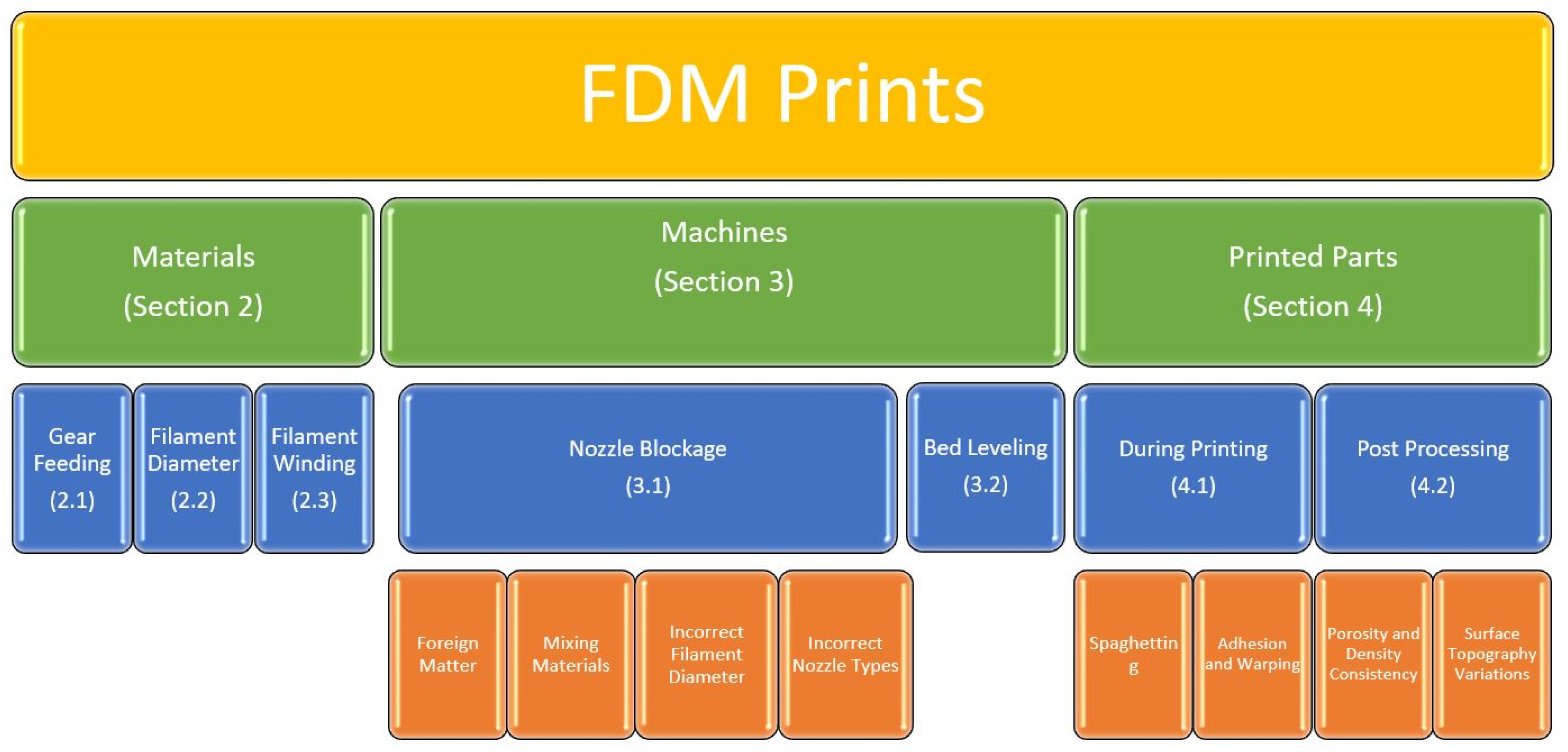
3. Failure and Flaws in Raw Feeding Materials

3.1. Gear Feeding

The gear feeding process consists of two cylinders with a tooth inlay, as shown in Figure 3. They are normally held with a screw spring that provides an adjustable tension for the extruding gears. This tension allows the gears to increase or decrease friction on the filament, which allows for the ease of movement when using different materials (PEEK, ABS, PLA, Carbon Fiber, etc.), as each material has a different hardness and density.
In 3D printing, there are two different feeding styles. The most common is Bowden extruding, where the gears feeding the filament are located on the body of the printer and a tube carries the filament to the thermal coupling hot end. An example of a 3D Filament printer that uses Bowden extruding is in Figure 4. This helps to reduce the possibility of breakage and thermocouple burnout.
For direct extruding printers, the extrusion gears are located behind the thermocouple hot ends. This has a lower failure rate due to the lack of tension placed on the filament and the reduced travel time between the gears and the thermocouple. However, it reduces the quality of the print because of the slop produced by the gear motors.
Both extruding systems normally have an eye or a light sensor attached behind the extruding gears to notify the printer when the filament runs out. This then pauses the printing process and allows it to cool down mid-print. When this occurs, the location and progress of the print are saved and allow the print to be continues once a new filament is loaded in. However, due to the location of the notification system being behind the gears, if the filament’s diameter has been chewed away, the print will fail. The notification system, being behind the failing location, will show the filament still being processed through the extruder, even though it has faulted. To remove issues such as these, it would be beneficial to relocate the notification system as close to the thermocouple location as possible or install a two-part system. A two-part notification will greatly increase the chance of catching a gear feeding failure quicker, reducing the possibility of a failed print. In both systems, one of the most common failures is gear slippage. There are two possible ways for this to occur.
One cause is moisture content within the filament itself. If the filament is too dry, it becomes brittle and encourages breaking. Due to the feeding pressure and possible twisting of the filament due to the unrolling process, snapping may occur between the gears and the feeding tube of the extrusion system. This causes separation between the two parts of the filament and reduces the chance of the gears catching the material and feeding it into the guide tube. If the gears gain traction on the filament, it has a high chance of pushing the material forward but missing the guiding tube. This then extrudes the filament into the air and out of the system, resulting in a failed print.
The second cause is the shedding of the filament into the gear’s grooves or the wearing down of the gear’s grooves. Both will result in the slipping of the gears against the filament and cause the diameter to be worn down over time. This will cause the filament to stay stationary within the system and keep any material from extruding from the hot ends. This will again cause the printer to “print air”. Since the sensor is behind the gear, the system will detect the material (even if it is stationary) and it will consider the material to be extruding from the hot ends and ruin the print.

3.2. Diameter

As mentioned above, the diameter of the filament plays a crucial role in the success of a printed object. The most common diameter sizes are 3.0 mm and 1.75 mm. The production of these filaments states that, over a certain length of the filament, the average diameter of it is one of those two values stated above. Due to the variations of the diameter within a tolerance range for these filaments, it is possible for the gear systems to lose traction on the filament and stop the material extrusion process (Figure 5).

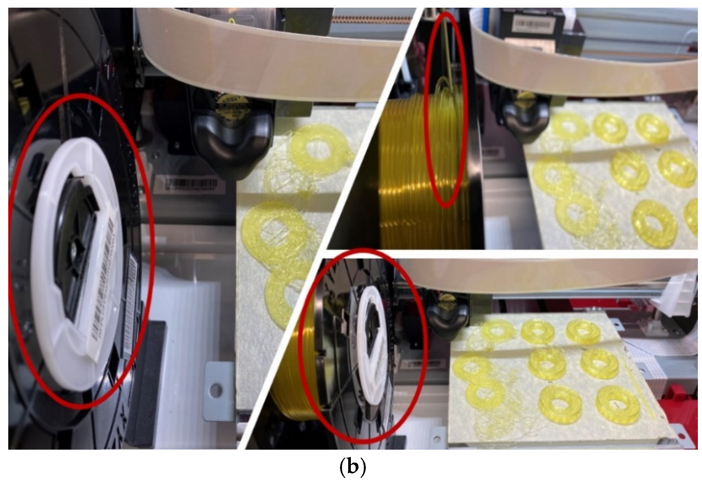
3.3. Filament Winding

Filament winding errors occur either during the winding process of the filament spool’s manufacturing or due to the failure of the tension while printing.

4. Failure and Flaws in Machines (3D Printers)

4.1. Nozzle Blockage

There are several possibilities for material to cause nozzle blockages while printing. Foreign matter, material mixing, and the filament diameter are some of the most common causes of nozzle blockages (Figure 6).

4.1.1. Foreign Matter Blockage

Focusing less on the machine and more on the environment the printer resides in, there are many different possibilities for material blocking. One of the most prominent is tape. There are several different filament manufacturers that initialize the coiling of the filament using tape to adhere it to the roll. Due to the light sensors mentioned above for the gear feeding, this causes one of two issues. The first issue is that the tape remains adhered to both the filament and the roll. This inadvertently causes the machine to be placed under tension, gear chewing on the filament, and a failed print. The second issue is that the tape dislodges from the roll yet remains adhered to the filament roll. As the gears continue feeding, this tape can stay attached to the filament and result in the clogging of the feeding tube or the extrusion nozzle.
In cases where the tape has clogged the feeding tube, it is necessary to remove and replace the whole tube due to the blockage. If the tape has clogged the extrusion nozzle, it is necessary to conduct a “hot push” of material. This is when the thermocouple of the extruder is heated to the top end of the temperature range of the filament and the filament is manually pushed through. In doing this, the tape is melted down with the filament and forcefully removed from the system. Theoretically, this will then completely remove the foreign material from the extruder.

4.1.2. Mixing Materials

The most commonly used filaments are PLA and ABS. The extrusion tips used for PLA can then be used for ABS after a hot push of the new material. This is due to the lower melting point of PLA. The hot push using ABS effectively removes any remaining PLA from the walls of the extrusion tip and allows for a clean extrusion of the new material. However, once a tip has been used for ABS, it is generally relegated to be used for only that material. This is because residual ABS on the walls of the extrusion tip remain, even after a hot push. This leads to an inconsistent temperature of the hot end and introduces impurities within the extruded filament, therefore ruining the print.
As stated previously in Section 1.1, FDM can be used to produce composites. When mixing those composites, it is very important to know the bonding mechanism, mechanical performance, fatigue behavior, rheological behavior, and thermal properties of the individual components [51,52,53,54,55,56,57]. The bonding mechanism between polymers can be affected by many different things. It all comes down to how the chemicals/polymers interact with each other. For example, a negatively charged polymer will not bind to another negatively charged polymer. Therefore, one of them has to have a positive charge for the bond to happen. These charges can be changed based on many different factors such as temperature or pH. These interactions can happen at the nanometer level, as evidenced by a paper published by Arkhurst et al. and Fan et al. [51,52]. Fan et al. go on to discuss how the mechanical properties of the polymers change the correlating properties of the composite. It was concluded by Fan et al. that when the bonding quality increased, so did the fracture strain limit [52]. When reviewing the fatigue behavior of polymeric composites, Shanmugan et al. discovered that this parameter has not been studied extensively and needs to receive further analysis [53]. Rheological behavior is how a polymer actually flows and moves as a liquid. This is extremely important for FDM printing since the polymer is heated and has to be pushed through a nozzle. Once it is cooled, it becomes a solid composite or, in the case of this paper, a PLA-based thermoplastic [55]. Thermoplastic composites are an extremely common type of plastic. These are made by heating a polymer to its melting point and then manipulating it to the desired shape. The consistent heat allows the polymer to stay in liquid form long enough for the composite to be shaped [54,58]. These composites can be used in many different ways such as cladding for walls or plastics that are nonbiodegradble or biodegradable depending on the application. In a study conducted by Park et al., it was found that adding an ABS polymer board to a cement wall curtain significantly increased the stability of the wall when the wind speed was increased to 150% [57]. Biodegradability has always been a hot topic when discussing polymers. In most cases, the mixture of polymers needs to be biodegradable. However, there are several cases in which the composite needs to have a high stability to resist biodegradation. In a study published by Harris et al., it was found that a composite that had a partial biodegrading blend had a better stability than blends that were made with nondegrading polymers [56].

4.1.3. Incorrect Filament Diameter

There are two commonly produced diameter extrusion tips: 3.0 mm is the largest diameter for most hobby printers, while the other diameter is 1.75 mm. When printing, it is imperative to ensure that the correct diameter filament is matched to the extruder tip. While it might not fail, it is generally not recommended to use a 1.75 mm filament in a 3.0 mm extruder. It increases the chance of introducing air to the extruded material and reducing the desired material properties of the filament. Most printer systems are set up to handle one of the two diameters. Common hobby printers are generally set up to use the 1.75 mm filament, and, as such, very few have the ability to plug-and-play a 3.0 mm conversion kit. This is mainly due to the light sensor for the material feeding, as well as the guiding systems used for the filament itself.

4.1.4. Incorrect Nozzle Types
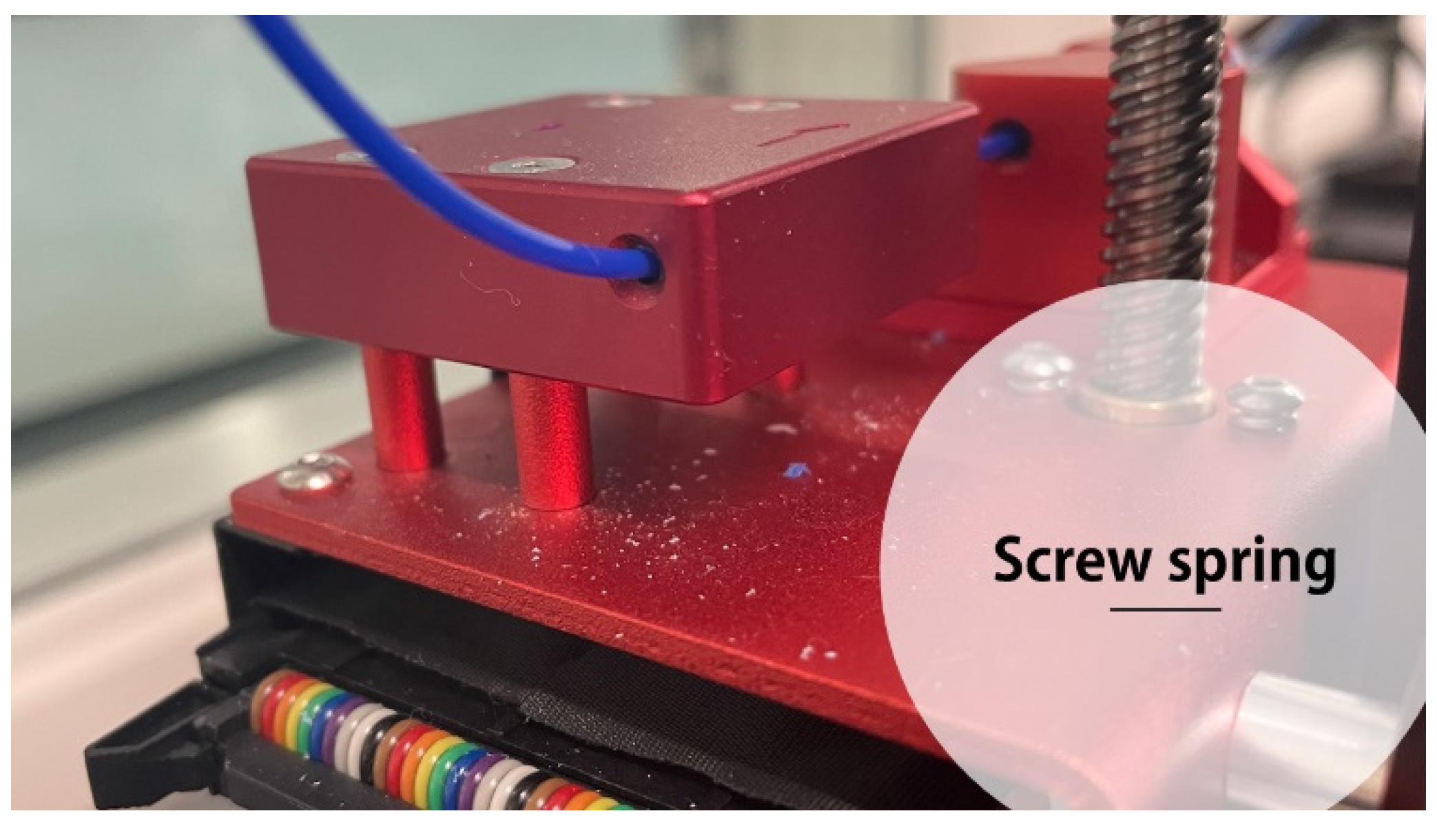
While the printers are focused on one of the two main diameter filaments, there can be an arrangement of extrusion point diameters. This information is required during the slicing software process. This will allow the software to calculate the movement speed of the print head, the cooling time, the layer thickness, and the layer height. It also calculates the tolerances and allows for the part’s shrinkage value. Generally, the larger the extrusion point, the more material there is that is used in a print, the higher the temperature needed during the initial extrusion, and the slower the movement speed. This allows for the filament to resolidify before the next layer is produced, while ensuring proper layer adhesion.
One of the main materials for extruder tips is brass. This information must be taken into account when printing due to the heat conductivity of the metal.

4.2. Bed Leveling

As the beginning of a printing process, it is recommended to go through a leveling process. For most slicing software, this is automatically coded into the system. This allows for the technician to ensure that the extruded material will meet the build plate at the proper height. Bed leveling at the initial start of the print will reduce the possibility of failure due to non-adhesion. However, for most non-enclosed sections, it is possible for the bed height and pitch to be adjusted during the print. If there is a pitch within the bed, there is a higher chance of non-adhesion for the extruded material (depending on the diameter of the extrusion nozzle itself).

5. Failure and Flaws in Printed Parts

5.1. Failures and Flaws during the Printing Process

Due to the nature of Additive Manufacturing, flaws and failures can be very costly and time consuming. In material removal processes, most can be remelted and then reproduced. For printing, due to the nature of the processes, any failure within the part or during the process will render the part unusable.

5.1.1. Spaghetting

Spaghetting is a failure that occurs when the material being extruded does not connect or adhere to the build plate but rather adheres to the extrusion nozzles (Figure 7). This is the unofficial term for this failure; however, it is a common issue and wastes large amounts of filament. One factor that causes this failure is foreign matter on the extruder tip. This is normally caused by old filament burning onto the nozzle from past prints. Another possibility is dragging. This is when the extrusion nozzle is not offset to correct for possible height differences in the print bed. The nozzle then drags across the build plate and removes some of the build plate material. This then melts and adheres to the extrusion nozzle and produces a possible adhesion point for the extruding material. This failure causes a large loss of material and failed prints if not rectified quickly. If the failure does occur, removing the material from the extrusion tip increases the chance of saving the print from a full failure.

5.1.2. Adhesion and Warping

The most common failure for adhesion is normally print bed adhesion. Print bed adhesion is the first few layers of the print and assists in keeping the print stationary. If the bed adhesion fails, the print will not progress. To reduce the chance of bed adhesion failure, it is recommended to use a heated and slightly abrasive surface. This will create friction for the filament and increase the chance of adhesion by increasing the surface area contact. Heated beds soften the extruded material, which in turn allows for the adhesion between the rough surface top layer and the first material layer [19,59].
Layer adhesion is another failure. This is when the extruded material fails to melt and adhere correctly to the previous layer. There are several factors that can cause this type of failure. One of the largest contributing factors is the environment. The ambient temperature of the area surrounding a print can cause the cooling process to alter during printing. If the ambient temperature is over the normal threshold for the print, it will cause the extruded material to cool at a slower rate, which can cause slippage. The exact opposite occurs when the ambient temperature of the printing area is cooler than the required temperature. This will cause the layers to not bond together.

5.2. Failures and Flaws after Processing

5.2.1. Porosity and Density Consistency

There are two main material property measurements. Porosity is a measure of the space within a part that is void of material, while density is defined as the measurement of mass per unit of volume. Regarding additive manufacturing, much like casting, trapped bubbles of air can occur during the printing process. Since the material is being extruded, there are instances where a bubble is introduced into the material while the print is occurring. Prints are produced in a linear pattern, which means there are micro-gaps between the layers and walls. These micro-gaps produce porosity in the prints. As such, due to the change in porosity, density is also affected. If the printed component is sectioned into different cross sections, the porosity and density of each varies. Voids cause fatigue, which, as stated earlier, is not a majorly discussed topic. In this article published in 2022, voids’ interaction with fatigue behavior is discussed [60]. The impulse excitation technique to find the Young’s modulus is a way to remedy this problem [61,62]. Through this process, the natural frequencies of the sample can be quantified, and then the mechanical properties can be calculated. It was found that when the Young’s modulus was calculated, an optimization of the geometry of the print could be performed to solve the porosity issues. Optimization of the print can be achieved in composites as well. It was found by Ahmed et al. that changing the printing parameters on the interfacial bond strength of ABS/carbon fiber-reinforced polylactic acid (CF-PLA) also changed the quality of the print [63].

5.2.2. Surface Topography Variations

Due to the layer printing technology used by FDM, the surface topography varies from component to component. As the machine prints, it extrudes semi-melted material onto the print surface or upon the previously laid layers. While this occurs, as stated previously in the paper, air bubbles can become trapped between layers, or the material can break during printing. If this happens, it can cause topography variations in the final component. While most of the errors are within tolerances, there are times where the topography varies widely. This can be due to the print failing and collapsing on itself or to air pockets being introduced on the surface [64]. A solution for this problem is to add various coatings that can increase the composite’s mechanical properties including the tensile strength of the composite. A battery of tests can then be done on the finished product, including the proposed methodology by Bernal et al. [61].

6. Discussion

The results from past experiments and research show that the ultrasound technology was highly effective in showing/recording defects and faults in both machined and purposefully produced defects within printed parts. In addition, ultrasound- and acoustic-based techniques showed promising capabilities for detecting acoustic signatures during the printing process and thus become a capable technique for the in situ monitoring of the machine and parts quality. Ultrasonic techniques can provide a rich amount of information about the quality of the part and the condition of the process. They are very precise and efficient in the post-process quality monitoring of the parts. However, the bottleneck of using ultrasonic for in situ monitoring is the speed of the data recording and analysis and the complexity of the data processing. Thermal-based techniques are still an effective method for quality monitoring, specifically in the FDM/FFF process, since the range of temperatures in FDM/FFF can be more easily included in the operational range of many thermal cameras. Future studies via thermal imaging are necessary to evaluate the appropriate characteristics of images, including resolution, speed, and accuracy for both the in-process and post-process assessment of the 3D printed parts’ quality.
When reproducing the experiments, the environment should be controlled. The ambient temperature and humidity need to be held constant and at an optimal level for the filament being used. The results will vary if the printer is enclosed versus open to the environment. If the printer is in a confined environment, feedback from the thermal imaging sensor will be expected and will artificially change the results. The testing application of the sensors for ultrasound technology should be repeated in a relatively constant spot to reduce errors and outlier data. These factors are very important practical points when designing a monitoring and/or control system for 3D printers since they affect the complex process of the 3D printing.
When NDT techniques are used for the in situ monitoring of the 3D printing processes, the immediate benefit would be the sustainability of the process, by which the dispensable waste of materials, energy, and production time can be eliminated if a serious flaw or inconsistency is detected in a layer. To reduce the false alarm in a monitoring methodology, in addition to the appropriate sensor integration, accurate and robust data analysis and signal processing are necessary. Machine learning and computer vision techniques can reduce the false alarm and enhance the accuracy of data analysis for this purpose [65].
To further develop the knowledge and understanding of the defects in 3D-printed parts and the potential failures in 3D printing machines, more investigations into both materials and manufacturing processes are necessary. Some of the suggested future work includes specific experimental investigations into the causes of defects in 3D-printed polymers and composites, studies on the optimization of manufacturing processes toward the minimum possibility of defect generation, studies on the cases of machine failures and the implementation of potential feedback controls to avoid such failures, and studies on the process parameters and their influence on faults and failures.

7. Conclusions

Additively manufacturing or 3D printing polymer and composite materials provides many opportunities for the design and fabrication of a variety of parts and components, specifically for parts with complex geometries, prototyping purposes, the fabrication of parts with low production rates, and tools and fixture design. Despite the valuable advantages that the 3D printing of polymers and composite materials such as FDM provides, the structural integrity and quality of the manufactured parts remain a main concern. Understanding the type and properties of the potential defects and flaws in 3D printed parts, as well as the potential failures in 3D printing machines, as discussed in this paper, is crucial to avoid manufacturing low-quality parts or operating the equipment in inappropriate conditions. The application of nondestructive testing should be conducted in all additively manufactured parts due to their destructible and degradable nature when checked by traditional methods. Due to their quick feedback and accuracy, thermal imaging, X-ray scattering, laser profilometry, and ultrasound are the most applicable nondestructive testing methods. They are able to be conducted in-line and after the processing of the part, and this allows for the early detection of defects as well as quality control.

Author Contributions

Conceptualization, M.B.-C.; methodology, M.B.-C.; investigation, M.B.-C. and E.L.; resources, M.B.-C.; writing—original draft preparation, M.B.-C.; writing—review and editing, H.T. and E.L.; supervision, H.T. and M.T.; project administration, H.T. and M.T.; funding acquisition, M.B.-C. All authors have read and agreed to the published version of the manuscript.

Funding

This research was funded by the Undergraduate Research Award of the Allen E. Paulson College of Engineering and Computing of Georgia Southern University under award number UGRA2020-MB.

Institutional Review Board Statement

Not applicable.

Informed Consent Statement

Not applicable.

Acknowledgments

The authors thank the undergraduate research program and the Dean’s office at the Allen E. Paulson College of Engineering and Computing of Georgia Southern University.

Conflicts of Interest

The authors declare no conflict of interest.

References

  1. Gibson, I.; Rosen, D.; Stucker, B.; Khorasani, M. Additive Manufacturing Technologies; Springer: Cham, Switzerland, 2020. [Google Scholar]
  2. Groover, M.P. Fundamentals of Modern Manufacturing; Wiley: Hoboken, NJ, USA, 2022. [Google Scholar]
  3. Zhao, H.; Liu, X.; Zhao, W.; Wang, G.; Liu, B. An Overview of Research on FDM 3D Printing Process of Continuous Fiber Reinforced Composites. In Journal of Physics: Conference Series; IOP Publishing: Bristol, UK, 2019; p. 052037. [Google Scholar]
  4. Pervaiz, S.; Qureshi, T.A.; Kashwani, G.; Kannan, S. 3D Printing of Fiber-Reinforced Plastic Composites Using Fused Deposition Modeling: A Status Review. Materials 2021, 14, 4520. [Google Scholar] [CrossRef] [PubMed]
  5. Singh, R.; Singh, S.; Mankotia, K. Development of ABS Based Wire as Feedstock Filament of FDM for Industrial Applications. Rapid Prototyp. J. 2016, 22, 300–310. [Google Scholar]
  6. Albakri, M.I.; Sturm, L.D.; Williams, C.B.; Tarazaga, P.A. Impedance-based non-destructive evaluation of additively manufactured parts. Rapid Prototyp. J. 2017, 23, 589–601. [Google Scholar] [CrossRef]
  7. Matterhackers. Available online: https://www.matterhackers.com/ (accessed on 6 December 2021).
  8. Makerbot Replicator. Available online: http://store.makerbot.com/replicator (accessed on 6 December 2021).
  9. Makerbot Replicator Mini. Available online: http://store.makerbot.com/replicator-mini (accessed on 6 December 2021).
  10. Cubify Cube Store. Available online: http://cubify.com/cube/store.aspx (accessed on 6 December 2021).
  11. Wickramasinghe, S.; Do, T.; Tran, P. FDM-Based 3D Printing of Polymer and Associated Composite: A Review on Mechanical Properties, Defects and Treatments. Polymer 2020, 12, 1529. [Google Scholar] [CrossRef]
  12. Blanco, I. The use of composite materials in 3D printing. J. Compos. Sci. 2020, 4, 42. [Google Scholar] [CrossRef] [Green Version]
  13. Kalsoom, U.; Nesterenko, P.N.; Paull, B. Recent developments in 3D printable composite materials. RSC Adv. 2016, 6, 60355–60371. [Google Scholar] [CrossRef]
  14. Triyono, J.; Sukanto, H.; Saputra, R.M.; Smaradhana, D.F. The effect of nozzle hole diameter of 3D printing on porosity and tensile strength parts using polylactic acid material. Open Eng. 2020, 10, 762–768. [Google Scholar] [CrossRef]
  15. Bhagia, S.; Bornani, K.; Agrawal, R.; Satlewal, A.; Ďurkovič, J.; Lagaňa, R.; Bhagia, M.; Yoo, C.G.; Zhao, X.; Kunc, V.; et al. Critical review of FDM 3D printing of PLA biocomposites filled with biomass resources, characterization, biodegradability, upcycling and opportunities for biorefineries. Appl. Mater. Today 2021, 24, 101078. [Google Scholar] [CrossRef]
  16. Swetham, T.; Reddy, K.M.M.; Huggi, A.; Kumar, M.N. A Critical Review on of 3D Printing Materials and Details of Materials Used in FDM. Int. J. Sci. Res. Sci. Eng. Technol. 2017, 3, 353–361. [Google Scholar]
  17. Zhu, Q.; Yu, K.; Li, H.Q.; Zhang, Q.Q.; Tu, D.W. Rapid residual stress prediction and feedback control during fused deposition modeling of PLA. Int. J. Adv. Manuf. Technol. 2022, 118, 3229–3240. [Google Scholar] [CrossRef]
  18. Kuo, C.C.; Wu, Y.R.; Li, M.H.; Wu, H.W. Minimizing warpage of ABS prototypes built with low-cost fused deposition modeling machine using developed closed-chamber and optimal process parameters. Int. J. Adv. Manuf. Technol. 2019, 101, 593–602. [Google Scholar] [CrossRef]
  19. Nazan, M.A.; Ramli, F.R.; Alkahari, M.R.; Abdullah, M.A.; Sudin, M.N. An exploration of polymer adhesion on 3D printer bed. IOP Conf. Ser. Mater. Sci. Eng. 2017, 210, 012062. [Google Scholar] [CrossRef]
  20. Taheri, H. Utilization of Non-destructive Testing (NDT) Methods for Composite Materials Inspection (Phased Array Ultrasonic). Master’s Thesis, South Dakota State University, Brookings, SD, USA, 2014. [Google Scholar]
  21. Lin, T.; Jia, D.; He, P.; Wang, M.; Liang, D. Effects of fiber length on mechanical properties and fracture behavior of short carbon fiber reinforced geopolymer matrix composites. Mater. Sci. Eng. A 2008, 497, 181–185. [Google Scholar] [CrossRef]
  22. Alves, M.; Junior, C.C.; Ha, S. Fiber waviness and its effect on the mechanical performance of fiber reinforced polymer composites: An enhanced review. Compos. Part A Appl. Sci. Manuf. 2021, 149, 106526. [Google Scholar] [CrossRef]
  23. Senthil, K.; Arockiarajan, A.; Palaninathan, R.; Santhosh, B.; Usha, K. Defects in composite structures: Its effects and prediction methods–A comprehensive review. Compos. Struct. 2013, 106, 139–149. [Google Scholar] [CrossRef]
  24. Kugler, D.; Moon, T.J. Identification of the most significant processing parameters on the development of fiber waviness in thin laminates. J. Compos. Mater. 2002, 36, 1451–1479. [Google Scholar] [CrossRef]
  25. Thor, M.; Sause, M.G.; Hinterhölzl, R.M. Mechanisms of origin and classification of out-of-plane fiber waviness in composite materials—A review. J. Compos. Sci. 2020, 4, 130. [Google Scholar] [CrossRef]
  26. Bednarcyk, B.A.; Aboudi, J.; Arnold, S.M. The effect of general statistical fiber misalignment on predicted damage initiation in composites. Compos. Part B Eng. 2014, 66, 97–108. [Google Scholar] [CrossRef] [Green Version]
  27. Li, Y.; Stier, B.; Bednarcyk, B.; Simon, J.-W.; Reese, S. The effect of fiber misalignment on the homogenized properties of unidirectional fiber reinforced composites. Mech. Mater. 2016, 92, 261–274. [Google Scholar] [CrossRef]
  28. Kidangan, R.T.; Krishnamurthy, C.V.; Balasubramaniam, K. Identification of the fiber breakage orientation in carbon fiber reinforced polymer composites using induction thermography. NDT E Int. 2021, 122, 102498. [Google Scholar] [CrossRef]
  29. Liu, T.; Gao, Y.; Fan, W.; Gao, X.; Ma, J. Predictions of the axial tensile property of the unidirectional composite influenced by microfiber breakage defects. Text. Res. J. 2022, 92, 15–29. [Google Scholar] [CrossRef]
  30. Taheri, H. Nondestructive Evaluation and In-Situ Monitoring for Metal Additive Manufacturing. Ph.D. Thesis, Iowa State University, Ames, IA, USA, 2018; pp. 61–75. [Google Scholar]
  31. Koester, L.W.; Bond, L.J.; Taheri, H.; Collins, P.C. Nondestructive Evaluation of Additively Manufactured Metallic Parts. Nondestruct. Eval. Mater. 2018, 17, 544–552. [Google Scholar] [CrossRef]
  32. Koester, L.W.; Bond, L.J.; Taheri, H.; Peter CCollins, P.C. Nondestructive evaluation of additively manufactured metallic parts: In situ and post deposition. In Additive Manufacturing for the Aerospace Industry; Elsevier Inc.: Philadelphia, PA, USA, 2018; Chapter 18; pp. 401–417. [Google Scholar] [CrossRef]
  33. Koester, L.W.; Taheri, H.; Bigelow, T.; Collins, P.C.; Bond, L.J. Nondestructive Testing for Metal Parts Fabricated Using Powder-Based Additive Manufacturing. Mater. Eval. 2018, 76, 514–528. [Google Scholar]
  34. Koester, L.W.; Taheri, H.; Bond, L.J.; Barnard, D.; Gray, J. Additive manufacturing metrology: State of the art and needs assessment. In AIP Conference Proceedings; AIP Publishing LLC: Melville, NY, USA, 2016; p. 130001. [Google Scholar]
  35. Borish, M.; Post, B.K.; Roschli, A.; Chesser, P.C.; Love, L.J. Real-Time Defect Correction in Large-Scale Polymer Additive Manufacturing via Thermal Imaging and Laser Profilometer. Procedia. Manuf. 2020, 48, 625–633. [Google Scholar] [CrossRef]
  36. Sauerbrunn, E.; Chen, Y.; Didion, J.; Yu, M.; Smela, E.; Bruck, H.A. Thermal imaging using polymer nanocomposite temperature sensors. Phys. Status Solidi. (A) 2015, 212, 2239–2245. [Google Scholar] [CrossRef]
  37. Shmueli, Y.; Jiang, J.; Zhou, Y.; Xue, Y.; Chang, C.; Yuan, G.; Satija, S.K.; Lee, S.; Nam, C.; Kim, T.; et al. Simultaneous In Situ X-ray Scattering and Infrared Imaging of Polymer Extrusion in Additive Manufacturing. ACS Appl. Polym. Mater. 2019, 1, 1559–1567. [Google Scholar] [CrossRef]
  38. Abdelrahman, M.; Starr, T.L. Quality certification and control of polymer laser sintering: Layerwise temperature monitoring using thermal imaging. Int. J. Adv. Manuf. Technol. 2016, 84, 831–842. [Google Scholar] [CrossRef]
  39. Giesko, T.; Zbrowski, A.; Czajka, P. Laser Profilometers for Surface Inspection and Profile Measurement. Probl. Eksploat. 2007, 97–108. [Google Scholar]
  40. Nguyen, H.T.; Crittenden, K.; Weiss, L.; Bardaweel, H. Experimental Modal Analysis and Characterization of Additively Manufactured Polymers. Polymer 2022, 14, 2071. [Google Scholar] [CrossRef]
  41. Liao, Y.; Liu, C.; Coppola, B.; Barra, G.; Di Maio, L.; Incarnato, L.; Lafdi, K. Effect of Porosity and Crystallinity on 3D Printed PLA Properties. Polymer 2019, 11, 1487. [Google Scholar] [CrossRef] [Green Version]
  42. Taheri, H.; Du, J.; Delfanian, F. Experimental Observation of Phased Array Guided Wave Application in Composite Materials. Mater. Eval. 2017, 75, 1308–1316. [Google Scholar]
  43. Taheri, H.; Hassen, A.A. Nondestructive Ultrasonic Inspection of Composite Materials: A Comparative Advantage of Phased Array Ultrasonic. Appl. Sci. 2019, 9, 1628. [Google Scholar] [CrossRef] [Green Version]
  44. Lee, J.; Hasanian, M.; Saboonchi, H.; Baechle, M.; Taheri, H. Ultrasonic evaluation of polymer additively manufactured parts for defect inspection and structural integrity assessment. In Nondestructive Characterization and Monitoring of Advanced Materials, Aerospace, Civil Infrastructure, and Transportation IX, 4; SPIE proceeding; SPIE Press: Bellingham, WA, USA, 2020; p. 70. [Google Scholar]
  45. Taheri, H.; Koester, L.; Bigelow, T.; Bond, L.J.; Braconnier, D.; Carcreff, E.; Dao, G.; Caulder, A.; Hassen, A.A. Fast Ultrasonic Imaging with Total Focusing Method (TFM) for Inspection of Additively Manufactured Polymer Composite Component. In Proceedings of the ASNT 27th Annual Research Symposium Proceedings, 10, Houston, TX, USA, 29–31 October 2018; pp. 212–220. [Google Scholar]
  46. Finnes, T. High Definition 3D Printing-Comparing SLA nad FDM Printing Technologies. J. Undergrad. Res. 2015, 13, 10–26. [Google Scholar]
  47. Kafle, A.; Luis, E.; Silwal, R.; Pan, H.M.; Shrestha, P.L.; Bastola, A.K. 3D/4D Printing of Polymers: Fused Deposition Modelling (FDM), Selective Laser Sintering (SLS), and Stereolithography (SLA). Polymer 2021, 13, 3101. [Google Scholar] [CrossRef] [PubMed]
  48. Szykiedans, K.; Credo, W. Mechanical Properties of FDM and SLA Low-cost 3-D Prints. Procedia Eng. 2016, 136, 257–262. [Google Scholar] [CrossRef] [Green Version]
  49. Bond, L.J.; Koester, L.W.; Taheri, H. NDE in-process for metal parts fabricated using powder based additive manufacturing. In Smart Structures and NDE for Energy Systems and Industry 4.0, 3; SPIE proceeding; SPIE Press: Bellingham, WA, USA, 2019; p. 1. [Google Scholar]
  50. Taheri, H.; Koester, L.W.; Bigelow, T.A.; Faierson, E.J.; Bond, L.J. In Situ Additive Manufacturing Process Monitoring With an Acoustic Technique: Clustering Performance Evaluation Using K-Means Algorithm. J. Manuf. Sci. Eng. 2019, 141, 041011. [Google Scholar] [CrossRef]
  51. Arkhurst, B.M.; Seol, J.B.; Lee, Y.S.; Lee, M.; Kim, J.H. Interfacial structure and bonding mechanism of AZ31/carbon-fiber-reinforced plastic composites fabricated by thermal laser joining. Compos. Part B-Eng. 2019, 167, 71–82. [Google Scholar] [CrossRef]
  52. Fan, C.Z.; Shan, Z.D.; Zou, G.S.; Zhan, L.; Yan, D.D. Interfacial Bonding Mechanism and Mechanical Performance of Continuous Fiber Reinforced Composites in Additive Manufacturing. Chin. J. Mech. Eng. 2021, 34, 11. [Google Scholar] [CrossRef]
  53. Shanmugam, V.; Das, O.; Babu, K.; Marimuthu, U.; Veerasimman, A.; Johnson, D.J.; Neisiany, R.E.; Hedenqvist, M.S.; Ramakrishna, S.; Berto, F. Fatigue behaviour of FDM-3D printed polymers, polymeric composites and architected cellular materials. Int. J. Fatigue 2021, 143, 15. [Google Scholar] [CrossRef]
  54. Yang, C.C.; Tian, X.Y.; Liu, T.F.; Cao, Y.; Li, D.C. 3D printing for continuous fiber reinforced thermoplastic composites: Mechanism and performance. Rapid Prototyp. J. 2017, 23, 209–215. [Google Scholar] [CrossRef]
  55. Arrigo, R.; Frache, A. FDM Printability of PLA Based-Materials: The Key Role of the Rheological Behavior. Polymer 2022, 14, 1754. [Google Scholar] [CrossRef] [PubMed]
  56. Harris, M.; Mohsin, H.; Potgieter, J.; Ishfaq, K.; Archer, R.; Chen, Q.; De Silva, K.; Le Guen, M.J.; Wilson, R.; Arif, K.M. Partial Biodegradable Blend with High Stability against Biodegradation for Fused Deposition Modeling. Polymer 2022, 14, 1541. [Google Scholar] [CrossRef] [PubMed]
  57. Park, M.J.; Bae, J.; Ju, Y.K. Structural Behavior of a Composite Curtain Wall Fabricated by the Fused Deposition Modeling 3D Printing Method. Polymer 2022, 14, 1431. [Google Scholar] [CrossRef]
  58. Sehhat, M.H.; Mahdianikhotbesara, A.; Yadegari, F. Impact of temperature and material variation on mechanical properties of parts fabricated with fused deposition modeling (FDM) additive manufacturing. Int. J. Adv. Manuf. Technol. 2022, 120, 4791–4801. [Google Scholar] [CrossRef]
  59. Nazan, M.A.; Ramli, F.R.; Alkahari, M.R.; Sudin, M.N.; Abdullah, M.A. Optimization of Warping Deformation in Open Source 3D Printer Using Response Surface Method. In Proceedings of the Mechanical Engineering Research Day, Melaka, Malaysia, 31 March 2016; pp. 71–72. [Google Scholar]
  60. Hassanifard, S.; Behdinan, K. Effects of voids and raster orientations on fatigue life of notched additively manufactured PLA components. Int. J. Adv. Manuf. Technol. 2022, 120, 6241–6250. [Google Scholar] [CrossRef]
  61. Bernal, J.D.B.; Silva, E.C.N.; Rubio, W.M. Characterization of effective Young’s modulus for Fused Deposition Modeling manufactured topology optimization designs. Int. J. Adv. Manuf. Technol. 2019, 103, 2879–2892. [Google Scholar] [CrossRef]
  62. Ahmad, M.N.; Ishak, M.R.; Mohammad Taha, M.; Mustapha, F.; Leman, Z.; Anak Lukista, D.D.; Irianto; Ghazali, I. Application of Taguchi Method to Optimize the Parameter of Fused Deposition Modeling (FDM) Using Oil Palm Fiber Reinforced Thermoplastic Composites. Polymer 2022, 14, 2140. [Google Scholar] [CrossRef]
  63. Ahmed, S.W.; Hussain, G.; Altaf, K.; Ali, S.; Alkahtani, M.; Abidi, M.H.; Alzabidi, A. On the Effects of Process Parameters and Optimization of Interlaminate Bond Strength in 3D Printed ABS/CF-PLA Composite. Polymer 2020, 12, 2155. [Google Scholar] [CrossRef]
  64. Jin, Y.; Wan, Y.; Zhang, B.; Liu, Z. Modeling of the chemical finishing process for polylactic acid parts in fused deposition modeling and investigation of its tensile properties. J. Mater. Process. Technol. 2017, 240, 233–239. [Google Scholar] [CrossRef]
  65. Taheri, H.; Gonzalez Bocanegra, M.; Taheri, M. Artificial Intelligence, Machine Learning and Smart Technologies for Nondestructive Evaluation. Sensors 2022, 22, 4055. [Google Scholar] [CrossRef]
Figure 1. Example of an FDM 3D printer with a polymer filament spool (top-left).
Jcs 06 00202 g001
Figure 2. Common defects posed by the FDM printing of polymers and composites.
Jcs 06 00202 g002
Figure 3. Screw spring that provides tension for the gear feeding process.
Jcs 06 00202 g003
Figure 4. Close-up of the gear feeding that uses the Bowden extruding style.
Jcs 06 00202 g004
Figure 5. (a) Location and arrangement of the filament spool inside the FDM/FFF 3D printer; (b) Instability (misalignment) of the filament spool winding (red circles) during the printing process.
Jcs 06 00202 g005aJcs 06 00202 g005b
Figure 6. Nozzle blockage fault in a 3D printing machine.
Jcs 06 00202 g006
Figure 7. Spaghetting of unsuccessful deposition of the melted filament material.
Jcs 06 00202 g007
Publisher’s Note: MDPI stays neutral with regard to jurisdictional claims in published maps and institutional affiliations.

