Article

An Experimental Study on Electrical Properties of Self-Sensing Mortar

by
Ramkumar Durairaj
1,
Thirumurugan Varatharajan
1,*,
Satyanarayanan Kachabeswara Srinivasan
1,
Beulah Gnana Ananthi Gurupatham
2 and
Krishanu Roy
3,*
1
Department of Civil Engineering, SRM Institute of Science and Technology, Kattankulathur 603203, India
2
Department of Civil Engineering, Anna University, Chennai 600025, India
3
School of Engineering, Civil Engineering, The University of Waikato, Hamilton 3216, New Zealand
*
Authors to whom correspondence should be addressed.
J. Compos. Sci. 2022, 6(7), 208; https://0-doi-org.brum.beds.ac.uk/10.3390/jcs6070208
Submission received: 21 June 2022 / Revised: 7 July 2022 / Accepted: 13 July 2022 / Published: 15 July 2022

Abstract

:
Self-sensing cementitious composites are a combination of conventional materials used in the construction industry along with any type of electrically conductive filler material. Research has already been carried out with various types of conductive fillers incorporated into cement mortars to develop a self-sensing material. Carbon fibres have been used as conductive fillers in the past, which is uneconomical. In order to overcome this drawback, brass fibres have been introduced. This study concentrates on the behaviour of self-sensing mortar under two different curing conditions, including air and water curing. The main aim of this paper is to determine the self-sensing ability of various types of smart mortars. For this purpose, an experimental study was carried out, with the addition of various brass fibres of 0.10%, 0.15%, 0.20%, 0.25%, and 0.30% by volume, to determine the electrical properties of cementitious mortar. In addition, different combinations of brass and carbon fibres were considered, such as 95% brass fibre with 5% carbon fibre, 90% brass fibre with 10% carbon fibre, and 85% brass fibre with 15% carbon fibre by volume, to determine the piezoresistive behaviour. A fractional change in electrical resistance was determined for all the mortar cubes. A fractional change in electrical resistance (fcr) is defined as the change in its electrical resistance with respect to its initial resistance (ΔR/R). Additionally, the temperature effects on self-sensing mortar under compressive loading were observed for various temperatures from room temperature to 800 °C (at room temperature, 200 °C, 400 °C, 600 °C, and 800 °C). It was observed that the addition of brass fibre to the cement mortar as an electrically conductive filler improved the self-sensing ability of the mortar. After 28 days of water curing, when compared to conventional mortar, the percentage increase in change in electrical resistance (fcr) was observed to be 26.00%, 26.87%, 27.87%, 38.55%, and 35.00% for 0.10%, 0.15%, 0.20%, 0.25%, and 0.30% addition of brass fibres, respectively. When the smart mortar was exposed to elevated temperatures, the compressive strength of the mortar was reduced. Additionally, the fractional change in electrical resistance values was also reduced with the increase in temperature. In addition to this, the self-sensing ability of smart mortars showed improved performance in water curing rather than in air-cured mortars. Compressive strengths, stress, strain, and change in electrical resistance (fcr) values were determined in this study. Finally, microstructural analysis was also performed to determine the surface topography and chemical composition of the mortar with different fibre combinations.

1. Introduction

Concrete is one of the most widely used materials in the construction industry. Conventional concrete is made up of readily and easily available raw materials such as sand, cement, and crushed stone aggregate. In order to improve the properties of conventional concrete and cementitious composites, different replacements for conventional materials have been investigated by researchers. Similarly, different additives have been added to the conventional mortar to enhance the properties of cementitious composites. Smart mortar is a cementitious composite developed to self-sense the damage in the structure and monitor structural health periodically. The use of smart cementitious composites in the structure will alert the occupants before failure and hence will reduce damage to their lives. Cementitious composites with various electrically conductive fillers were developed to produce a self-sensing mortar [1,2]. Electrically conductive fillers used in cementitious composites were mainly carbon-based, such as carbon fibre [3,4,5,6,7], carbon black [8,9,10,11], carbon nanofibre [12,13,14,15,16], and graphene [17,18]. One such invention is carbon-based electrically conductive filler invention nanotubes [19,20,21,22,23]. In the previous research, the carbon fibre added to cement mortar was assessed for its self-sensing capability of failure. Various comparisons have also been carried out between surface and volume resistance, two-probe, and four-probe methods to determine its effectiveness [24,25,26]. Polypropylene fibre was added to the concrete for the thermal study. When exposed to heat, the polypropylene fibres form voids in the concrete after melting [27,28]. A better threshold value was observed for mortar with the addition of carbon fibre as conductive filler of 6 mm than in 3 mm length fibres [29,30].
Cementitious nanocomposites consisting of 0.1% carbon nanotubes (CNT) with the weight of cement and 0.3% carbon nanofibre (CNF) with the weight of cement showed improved electrical resistivity and strain-sensing behaviour [31,32,33,34]. When carbon nano fibres were used, there was no self-sensing behaviour seen when the fraction of the fibres was less than 2.5%. Self-sensing behaviour was observed with a volume fraction of fibre greater than 2.5% [35]. Graphene nanoplatelets (GNP) and graphene oxide nanoplatelets (GONP) added to a mortar sample with the proper water–cement ratio improved the electrical resistance of the mortar and the piezoresistive effect [36]. Electrically Conductive Concrete (ECON) was used as heated pavement in an international airport. Lower fibre content was observed practically due to the loss of carbon fibres during the mixing process and degradation by the aggregates [37]. When compared to the stress, graphene added to cementitious material exhibited linear electrical resistance behaviour [38]. Use of multiwalled carbon nanotubes showed an improved response when subjected to vehicular load. Hence, they are effectively used for traffic monitoring and vehicle speed detection [39]. When graphite was used in lower amounts, the unit strain caused was higher than the electrical resistivity values [40]. Electrically conductive cementitious composites prepared with the addition of hybrid carbon fibres and carbon nanotubes under cyclic loading show linear behaviour of resistivity with both applied load and strain of material [41]. Carbon nanotubes with a high aspect ratio showed improved mechanical properties [42,43,44,45]. Carbon fibre and steel fibre added to cement mortar with a volume fraction of 0.36%, which showed better piezo resistivity than the 0.72% volume fraction [46]. At 0.5% volume fraction, tests with copper wire meshes inserted in the four-probe method revealed an improved relationship between strain and electrical resistance, established for the change in electrical resistance and its compressive strain [47]. Fibres were extensively used as electrically conductive fillers due to their additional benefits like crack arrestor, high ductility, high mechanical properties, and resistance to damage [48]. Steel fibres and carbon fibres were used as conductive fillers to analyse the behaviour of cementitious composites [49]. Carbon nanofibres have also been used to investigate the properties of cementitious composites [50]. Similarly, brass fibres were used to analyse the behaviour of mortar. The use of fibres as electrically conductive fillers was investigated by many researchers to develop a successful self-sensing cementitious composite.
Several types of conductive fillers have been used in past studies conducted by the researchers. One such conductive filler is intrinsic self-sensing concrete. From the extensive review on intrinsic self-sensing concrete (ISSC), it was concluded that the ISSC has many advantages, such as enhanced mechanical properties, high sensitivity, and easy installation [1]. Similarly, carbon fibres have been used widely in previous research conducted. Carbon fibres added to the mortar by 0.7% weight of cement along with 2.5% graphite by the weight of cement produced an effective smart mortar with higher sensitivity to stress and strain [5]. A Piezoresistivity cement-based stress or strain sensor (PCSS) was produced with the addition of carbon fibre and carbon black. The relationship between stress or strain and the fractional change in electrical resistivity was determined as Δ ρ = −0.022ε (Δ ρ = −1.35σ) [6]. Carbon fibres and multiwall carbon nanotubes incorporated into reinforced cement concrete beams of length 1000 mm, width 100 mm, and depth 150 mm resulted in better behaviour with the addition of carbon fibres rather than carbon nanotubes. Results showed that the addition of carbon fibres improved the load-carrying capacity and ductility with a higher sensitivity to the electrical resistance of the beam [11]. Carbon fibres of 5 mm length were added in cement mortar at a 0.2% to 0.5% volumetric ratio. A similar and linear relationship was found between stress vs. strain and resistance vs. strain graphs [15]. Carbon fibres with a length of 5–7 mm at a dosage of 0.5% to 10% by mass of cement reinforced in cement mortar improved piezoresistive behaviour. The surface resistance is high at initial impact and then reduces drastically at 5–40 impacts due to the loss of connection between distributed fibres [24].
The other type of conductive filler is brass fibre. Similarly, when brass fibres from the electrical discharge machining process were added to cement mortars, they improved the flexural strength with a reduction in compressive strength [13]. The addition of brass fibres of greater length and in larger amounts increases the thermal conductivity of the cement mortar [14]. Brass fibres added to the cement mortar with a fibre content of 0.25% volumetric ratio improved the piezoresistivity of the mortar [37]. Hybrid microsteel and carbon fibres added to cement mortar improved the conductivity of the mortar, as the hybrid fibres have better dispersion in the cement matrix when compared to monofibres [45].
Brass fibres were added to the concrete as conductive fillers, along with crushed limestone aggregate as coarse aggregate. Crushed limestone 0–5 mm was used for 60% of the concrete mix, and 40% of crushed limestone of size 5–15 mm was used. The better piezoresistivity was observed in compressive and tensile loading conditions [47]. When brass fibres were added to the concrete, a linear relationship was observed between electrical resistivity and temperature, with the temperature ranging between 25 °C and 50 °C. Hence, after 150 °C, the electrical resistivity changes dramatically and hence can be used as a fire alarm sensor [50]. Another invention in conductive filler is carbon nanotube. Use of electrostatic self-assembled carbon nanotubes and carbon black to create self-sensing concrete resulted in reduced compressive strength with an increase in flexural strength and electrical conductivity of cement mortar [7]. Effective dispersion of multi-walled carbon nanotube (MWCNT) is achieved by the use of low-concentrated dispersive additives along with sonication [20]. Carbon nanotubes added to cement mortar subjected to repeated compressive and impulsive loading showed a linear relationship between loading and electrical resistance, which can be effectively used for traffic monitoring [21]. Similarly, carbon nanofibre-reinforced reactive powder concrete was formed with the addition of silica fume and fine and coarse quartz sand, along with conventional constituents. When compared to carbon nanofibres added to mortar, carbon nanofibres reinforced in reactive powder concrete are more conductive and sensitive [33]. Carbon nanofibre-added specimens tested at AC voltage were more stable than specimens tested at DC voltage, with a fibre dosage greater than 2.5% volume of cement [34]. Additionally, the addition of carbon black to the cement mortar up to 4% of cement mass improved the mechanical properties, whereas the addition of carbon black by 7–10% of cement mass improved the piezoresistive properties [8]. Graphene nanoplatelets (GNP) and carbon black (CB) were used to make self-sensing cementitious composites. The use of these nanomaterials improved the electrical resistivity and durability of the materials [10].
Analysis of the axial and torsional free vibrations of cantilever and doubly clamped nanobeams serves to demonstrate the effectiveness of the stress-driven mixture [51]. The thermal characterization of Nylon 6 based nanocomposite (NC) material was carried out, which resulted in effective dispersion of the fibres with high thermal resistivity [52]. Cement mortar specimens with photopolymers or titanium alloy fibres were prepared and short beam shear tests were carried out. The results showed that the surface roughness affects the energy absorption of the material [53].
In the construction industry, concrete consists of Ordinary Portland cement (OPC). It is the most commonly used construction material because of its raw material availability and low cost. However, OPC production requires argillaceous and calcareous materials and is energy-intensive. The main reasons for the emission of greenhouse gas during the production of OPC are calcination and fossil fuel combustion [54]. Incorporation of Micro-silica (MS) in concrete enhances the mechanical properties related to uniformity, workability, strength, impermeability, durability, constructability, resistance to chemical attacks, reinforcement corrosion, and increases its compressive strength than that of cementitious materials [55]. Results of 15 push-off tests determined, with a high degree of precision, the longitudinal splitting characteristics of a concrete slab in a novel steel-concrete composite beam with headed shear stud connectors [56]. A durable structure with less greenhouse gas emission and with less energy could be obtained by the addition of fly ash to the concrete [57,58]. Experimental investigation on the influence of steel fiber reinforcement at the plastic hinge length of the concrete slab under repeated loading which includes the mechanical properties such as compressive strength and tensile strength of M20-grade concrete that is used for casting specimens are tested through the compressive strength test and the split tensile strength test [59]. Biochar, a carbonaceous solid material produced from the waste source poultry litter, is utilized as a renewable resource to replace cement content while making mortar which is being used in the construction industry [60].
Since carbon fibres do not withstand elevated temperatures, an alternative fibre (brass fibre) with self-sensing ability was used in this study. The objective of this research is to determine the self-sensing ability of mortars with the addition of two different types of fibres with varying fibre content. Smart mortar was made with the addition of brass fibres with the volumetric ratios of 0%, 0.10%, 0.15%, 0.20%, 0.25%, and 0.30%. These specimens were subjected to compression loading. Combinations of brass fibres and carbon fibres were also introduced, including 95 percent brass fibre with 5% carbon fibre, 90 percent brass fibre with 10% carbon fibre, and 85 percent brass fibre with 15% carbon fibre. The specimens were cured for 7, 14, and 28 days in two separate curing conditions: air curing and water curing. After 28 days of water curing, the specimens were subjected to elevated temperatures before undergoing a compression test. All of the specimens’ electrical data, as well as their compressive strength and strain, were recorded.
The research work carried out in the past is mainly based on the use of carbon-based materials as electrically conductive fillers in cementitious composites. Limited research work has been carried out using brass fibre as a conductive filler material to achieve an efficient self-sensing mortar or concrete. Hybrid fibres are also rarely used as conductive fillers in self-sensing cementitious composites. As a result, the current work focuses on the incorporation of brass fibres in traditional masonry mortar mixes to create the self-sensing mortar. To investigate the piezoresistive behaviour of the mortar mix, several combinations of brass and carbon fibres were also added.

2. Materials and Methods

Experimental work was performed to determine the electrical measurements, strain, and compressive strength of the mortar cubes. The cubical specimens used in this study were of size 50 × 50 × 50 mm to find the optimum percentage of brass fibre added to the mortar mix to produce an efficient self-sensing mortar. Similarly, different combinations of hybrid brass fibres and carbon fibres were added to the conventional mortar mix to investigate its piezoresistive behaviour. The cubical mortar specimens were air-cured (temperature is 28 °C and the relative humidity is 50%) and water-cured with a curing period of 7, 14, and 28 days.

2.1. Materials

In this research, the materials used to produce self-health monitoring mortar are mentioned below. OPC grade 53 was used to make the mortar mix. The specific gravity of cement used was 3.12 g/cm3. The bulk density of cement is 1440 kg/m3 with a fineness modulus of 285 m2/kg. To strengthen the cement, silica fume was mixed in with the regular Portland cement. According to the Indian standard code, the ratio of silica fume to cement was set at 15%. The specific gravity of silica fume used was 2.2 g/cm3. The bulk density of silica fume is 1350 kg/m3 with a fineness modulus of 22,000 m2/kg. The water/cement ratio (w/c) was set at 0.50 for all specimens, and potable water was used. This mortar mix has a cement content of 468 kg/m3. A superplasticizer was used to lower the water content of the mortar mix. The superplasticizer to cement weight ratio was set at 1.5 percent for all mixtures. The fine aggregate was river sand, which has a specific gravity of 2.70. According to IS 2250-1981, the cement to fine aggregate ratio in mortar mix was set at 1:3.

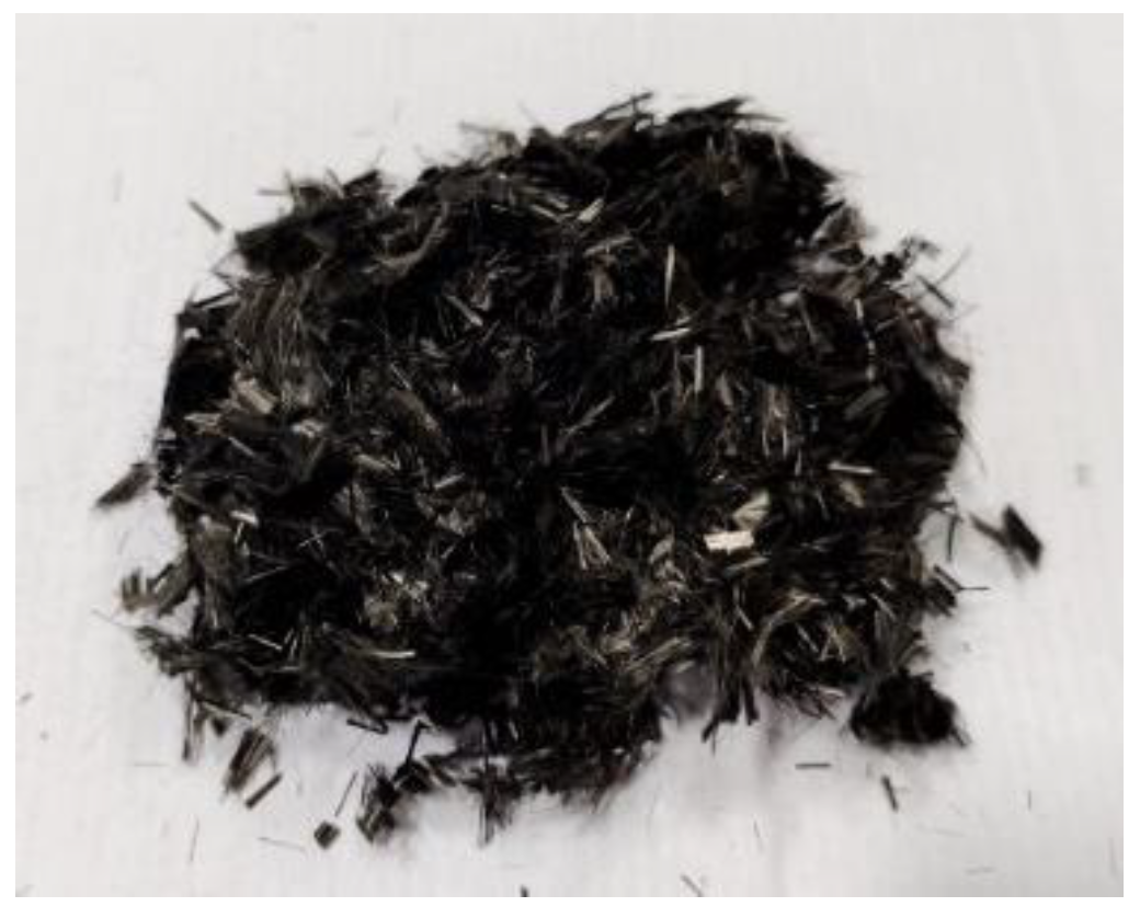
2.1.1. Addition of Brass Fibres

As shown in Figure 1, brass fibres of randomly varying sizes from 0.1 mm to 1 mm were used as an electrically conductive filler material. The specific gravity of the brass fibre used in this study was 8.4. The tensile strength of the brass fibre is 280 MPa. The shear modulus of the brass fibre is 40 GPa. The tension modulus of the brass fibre is 125 GPa. The electrical resistivity of carbon fibre is 6.5 × 10⁻⁶ Ωcm. The brass fibres were added to the mortar mix with different fibre percentages of 0%, 0.10%, 0.15%, 0.20%, 0.25%, and 0.30% by volume.

2.1.2. Addition of Hybrid Brass and Carbon Fibres

Brass fibres of randomly varying sizes from 0.1 mm to 1 mm were used along with carbon fibres as an electrically conductive filler material. As shown in Figure 2, carbon fibres were 5 mm in length and 10 µm in diameter. The specific gravity of the carbon fibre used in this study was 1.6. The tensile strength of the carbon fibre was 690 MPa. The tension modulus of the carbon fibre was 48 GPa. The electrical resistivity of carbon fibre is 3.0 × 10⁻³ Ωcm. Hybrid brass fibres and carbon fibres were added in different combinations, such as 95% brass fibre with 5% carbon fibre, 90% brass fibre with 10% carbon fibre, and 85% brass fibre with 15% carbon fibre. The volumetric ratio of brass fibres added was 0.25% to its volume and carbon fibres added was 0.24% to its volume.

2.2. Casting of Specimen

In this study, the four-probe method was adopted. Two methods were used to determine the electrical resistance, namely the insertion of wire meshes and the wire winding method. Insertion of mesh is comparatively better than the winding method. Since the mesh is completely inserted into the specimen, the resistivity is determined throughout the cross-section, whereas in the winding method, the wires are only in contact with the outer surface area of the specimen, and it does not involve the entire cross-section of the specimen, resulting in a poor sensing effect. The insertion of wire meshes method is adopted in the present work. The four-probe method was used in this experimental study in which four steel meshes were inserted into each cubical specimen at an equal spacing between them. The cubical specimens were cast and placed at room temperature for 24 h. The specimens were demoulded and placed in water and air for curing.

2.2.1. Addition of Brass Fibres

Initially, cement, sand, and silica fume were added and mixed thoroughly by hand. The required amount of superplasticizer was added to the required amount of water. This mixture was poured into the mixed dry constituents. The mixture was placed in the mortar mixer machine and allowed to mix properly. The brass fibres were added to this mixture and stirred for 2 min in the same mortar mixer to ensure uniform distribution of fibres. After that, the fresh mix was put into the steel cubical moulds, and steel wire meshes were installed as indicated in Figure 3.

2.2.2. Addition of Hybrid Brass and Carbon Fibres

To begin, methyl cellulose was dissolved in water, and then carbon fibre was added to the mix. Hand mixing was used to properly combine this mixture. To the aforesaid combination, cement, silica fume, sand, water, and superplasticizer were added and mixed for 2 min. To ensure uniform distribution of both fibres, the brass fibres were added to the mixture and mixed for an additional 2 min in the same mortar mixer. The steel wire mesh was then introduced into the mix and poured into the steel cubical moulds, as shown in Figure 4.

2.3. Test Method

For all the specimens, electrical measurements were taken using the four-probe approach, as illustrated in Figure 5. A Universal Testing Machine (UTM) was used to conduct the strain-sensing and damage-sensing tests. The load was measured using a UTM, and the strain was measured with a strain gauge, as illustrated in Figure 6. Strain measurements were taken with strain gauges mounted on either side of the cubical specimens at each increment of load. The electrical measurements of the cubical mortar samples were obtained using a digital multimetre.

2.4. Temperature Study

An elevated temperature study was carried out with the optimised percentage of brass fibre (0.25% by volume of mortar) and optimised brass carbon hybrid fibres (95% brass fibre with 5% carbon fibre). The specimens were made with the optimised fibre content and then cured for 28 days in water, since water curing was observed to be better than air curing during optimization. After 28 days of water curing, the specimens were placed in a box furnace for four hours with different temperature variations like room temperature, 200 °C, 400 °C, 600 °C, and 800 °C. The specimens were then subjected to compressive loading. The compression values and the electrical measurements were recorded.

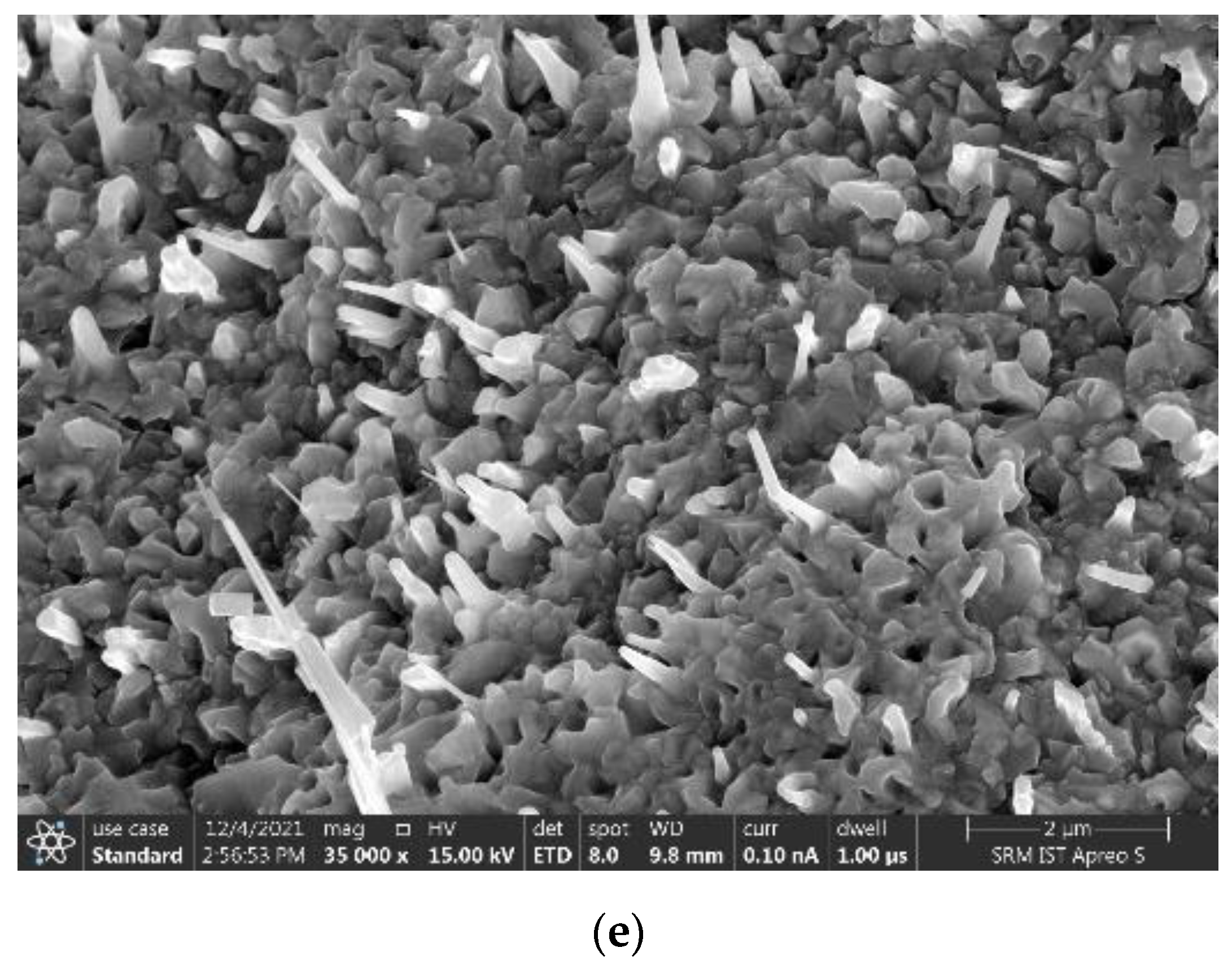
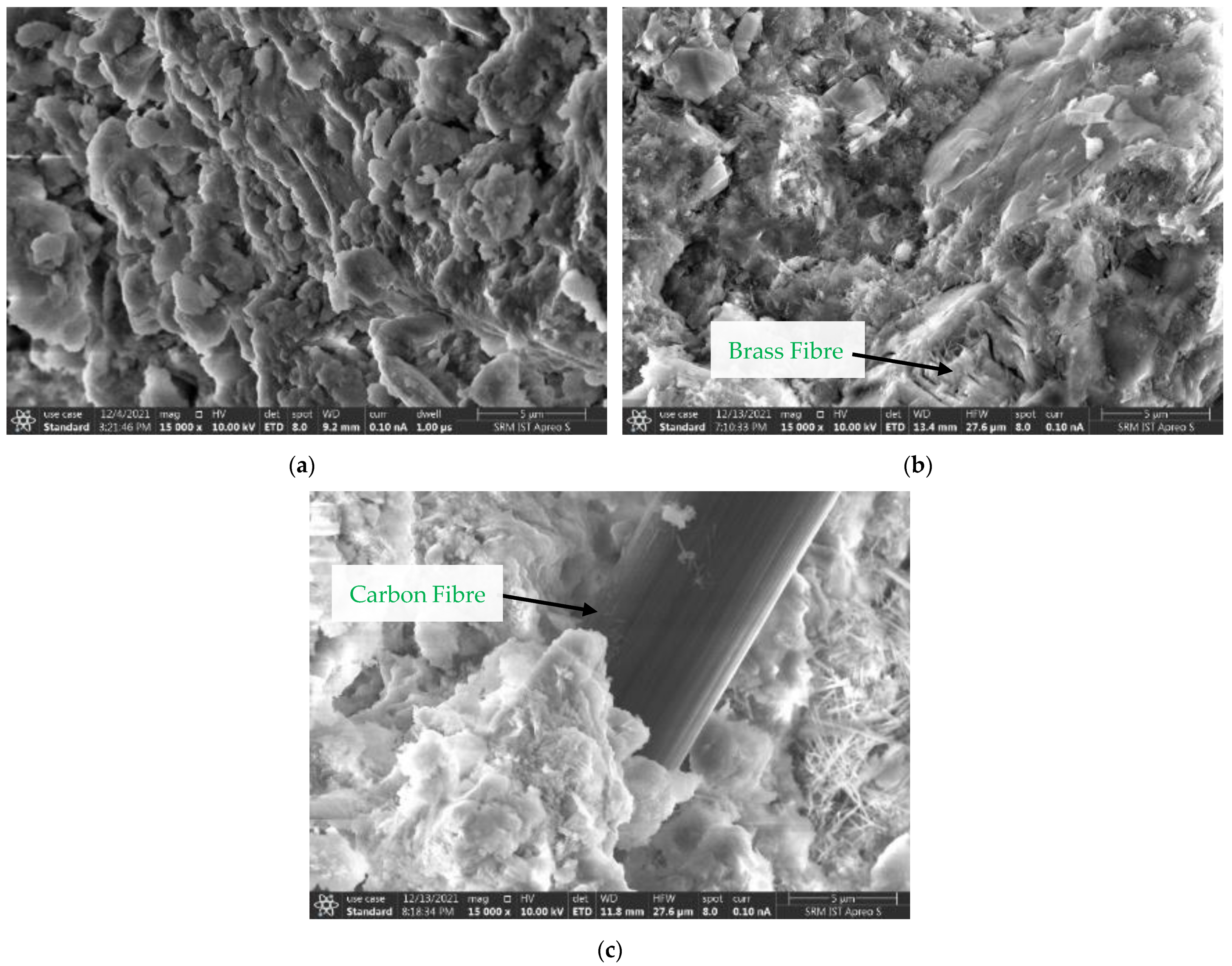
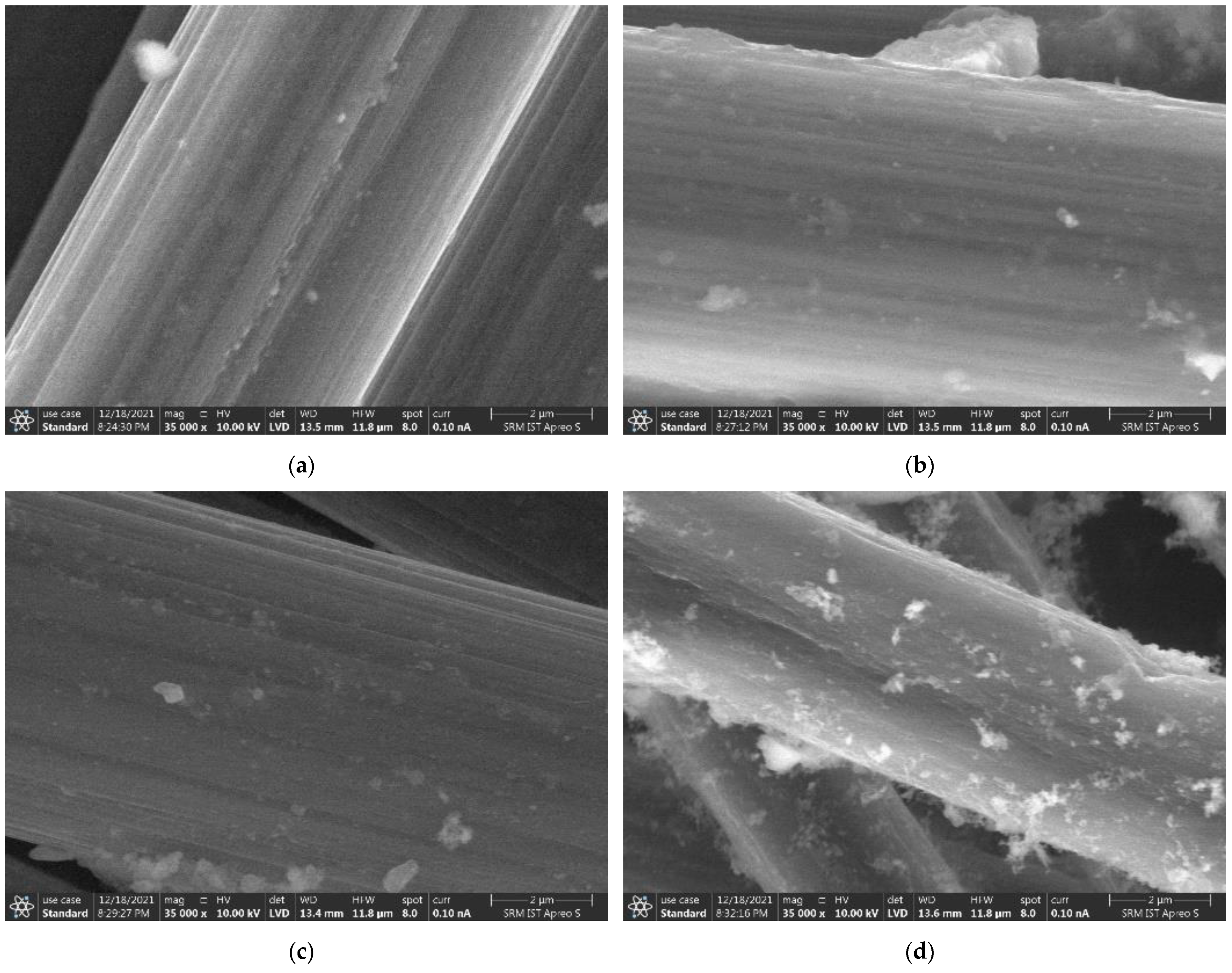
2.5. Micro-Characterization

Surface topography imaging of the specimens under high magnification was carried out using a Scanning Electron Microscope (SEM). Raw brass fibres and carbon fibres were subjected to elevated temperatures in a box furnace for a duration of four hours. These samples were magnified under SEM to visualise the surface topography. Similarly, these samples were subjected to Energy Dispersive Spectroscopy to perform element analysis. The fibres added to mortar samples were also observed under a SEM for understanding their bonding and dispersion of the mortar mix.

3. Discussion and Findings

The load was applied with a 2 kN increment in UTM. A strain gauge and a digital multimetre were used for testing. The fractional change in electrical resistance (fcr) was determined using the resistance value for each 2 kN increment in load.

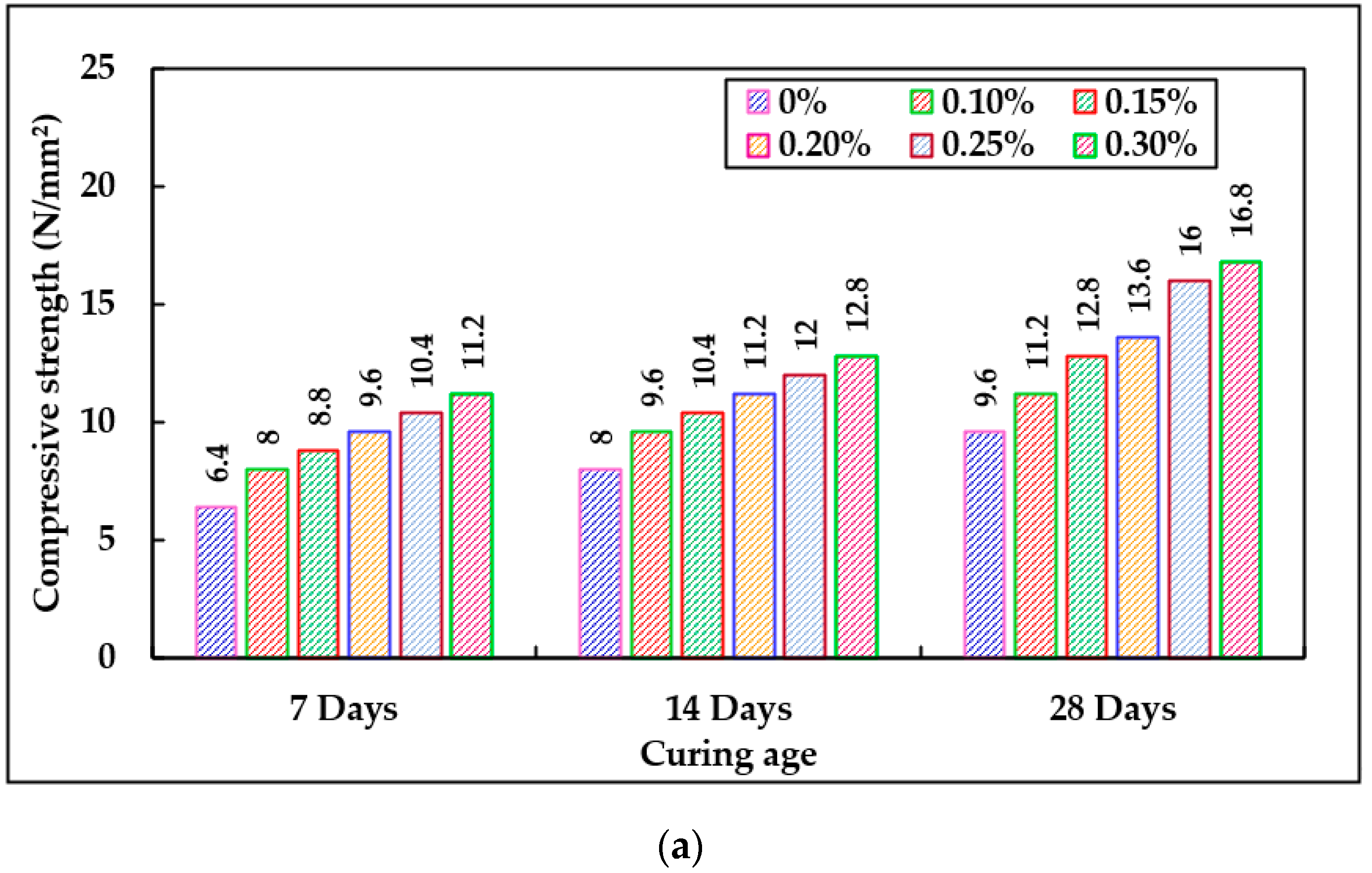
3.1. Compression Test

3.1.1. Brass Fibre Addition

After 7, 14, and 28 days of air curing, for 0.25% addition of brass fibres to the mortar mix, the compressive strength rose by 62.5%, 50%, and 66.66%, respectively. Similarly, when 0.25% brass fibres were added to the cement mortar mix during water curing, the compressive strength increased by 40%, 33.33%, and 60%, as shown in Figure 7. The compressive strength of the mortar was higher when a smart mortar was used. This is due to the presence of steel grids embedded into the mortar specimen. The fibres added to the mortar improved the compressive strength, and the additional increase was caused by the presence of steel grids.

3.1.2. Addition of Hybrid Brass and Carbon Fibres

Cement mortar’s compressive strength rose by 75%, 60%, and 75% for 95% brass fibre with 5% carbon fibre added to the mortar mix for 7, 14, and 28 days of air curing, respectively. Similarly, cement mortar’s compressive strength rose by 60%, 41.6%, and 71.43% for 95% brass fibre with 5% carbon fibre added to the mortar mix in water curing. Cement mortar’s compressive strength rose by 62.5%, 40%, and 66.66% for 90% brass fibre with 10% carbon fibre added to the mortar mix in air curing. Similarly, cement mortar’s compressive strength rose by 40%, 33.33%, and 42.85% for 90% brass fibre with 10% carbon fibre added to the mortar mix in water curing. Cement mortar’s compressive strength rose by 50%, 30%, and 41.67% for 85% brass fibre with a 15% carbon fibre added to the mortar mix in air curing as shown. Similarly, cement mortar’s compressive strength rose by 40%, 25%, and 35.71% for 85% brass fibre with 15% carbon fibre added to the mortar mix in water curing, as shown in Figure 8.

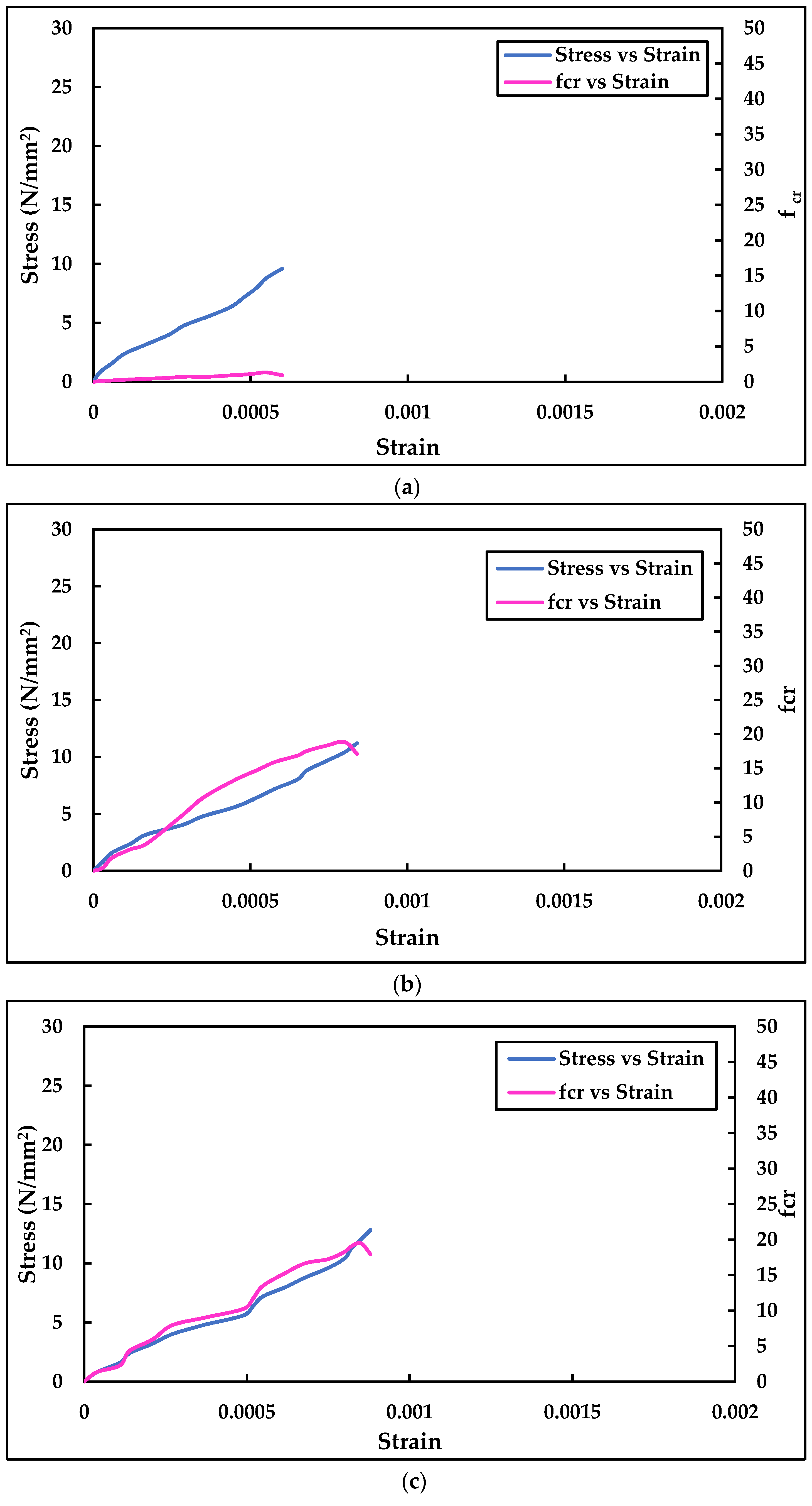
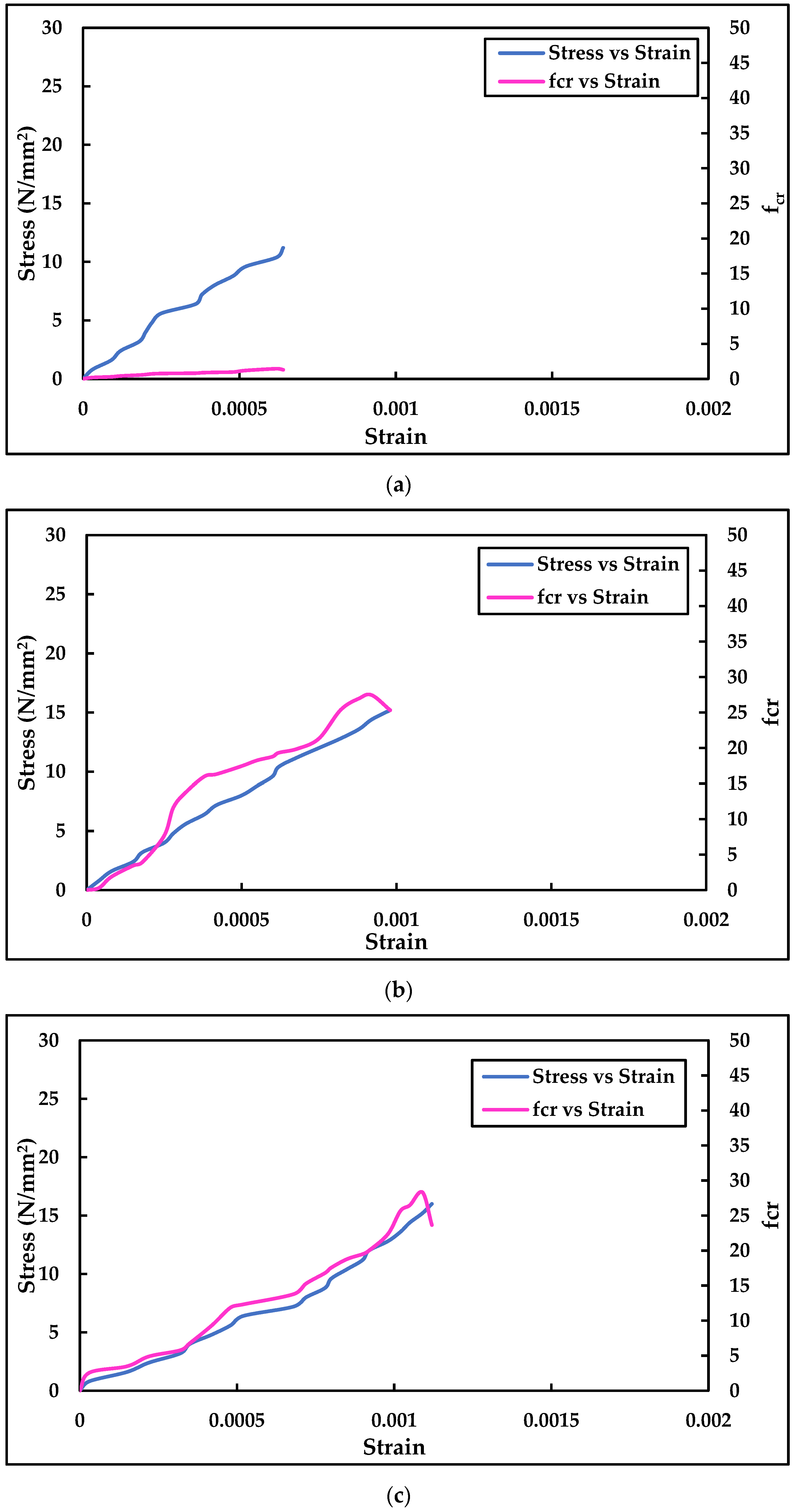
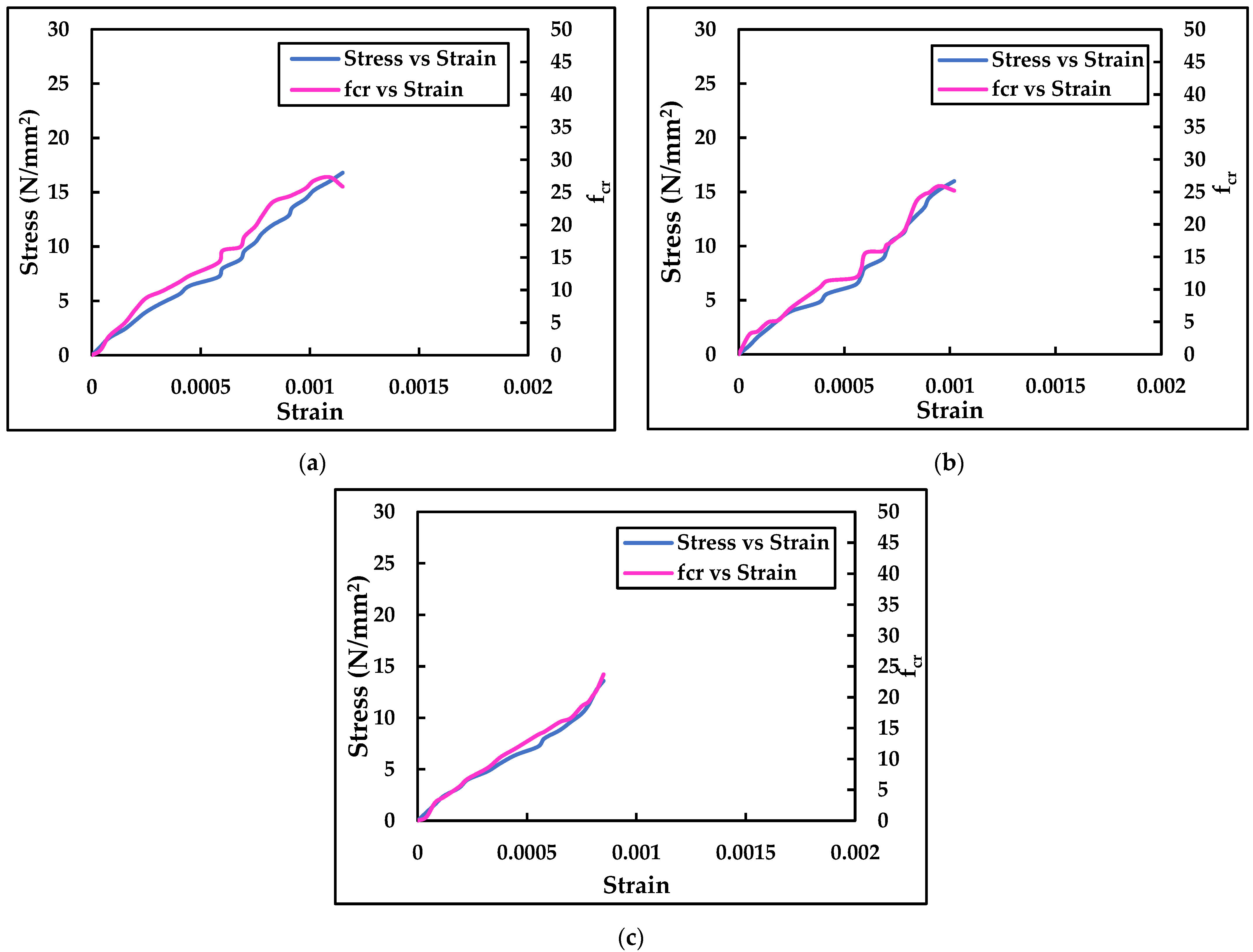
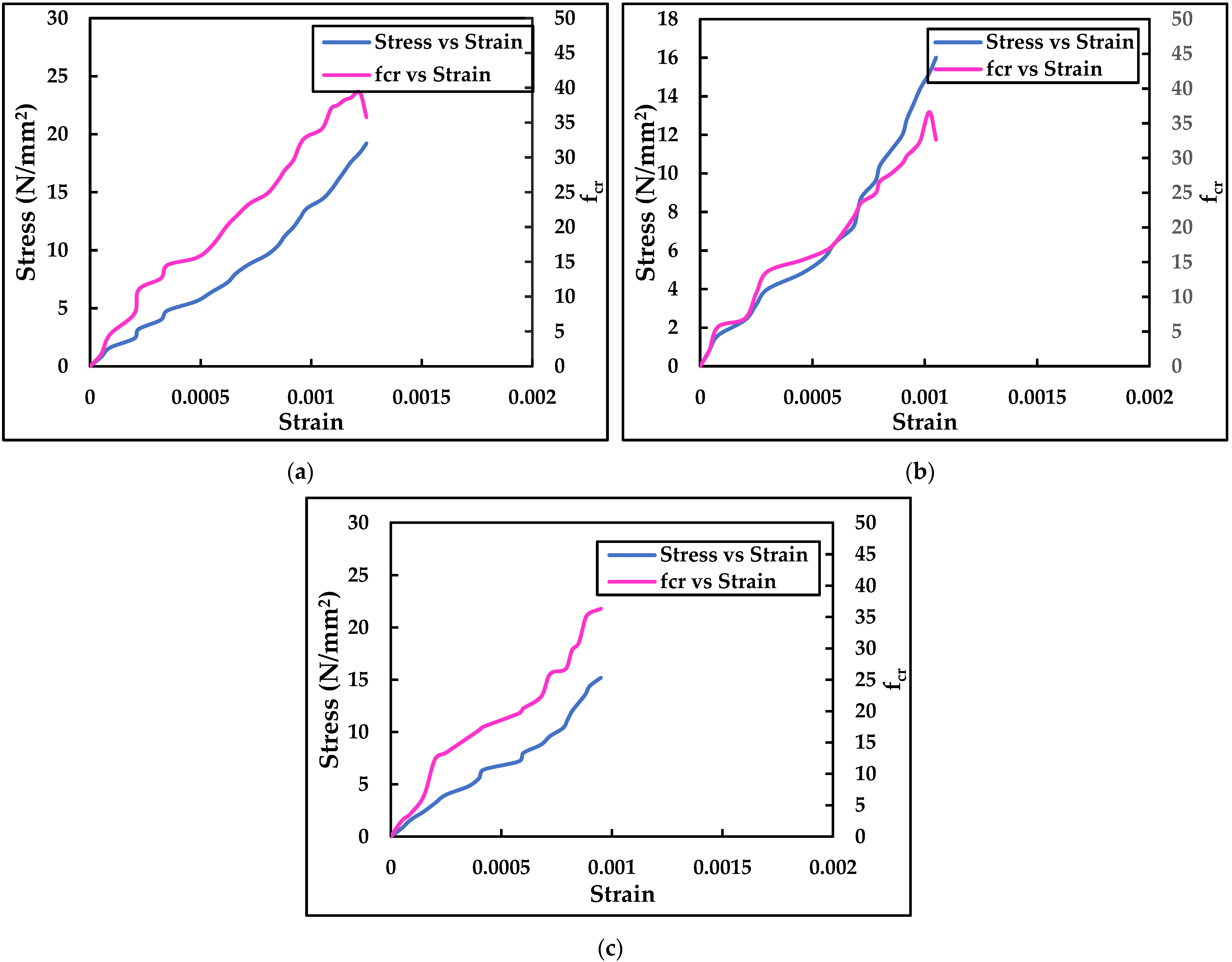
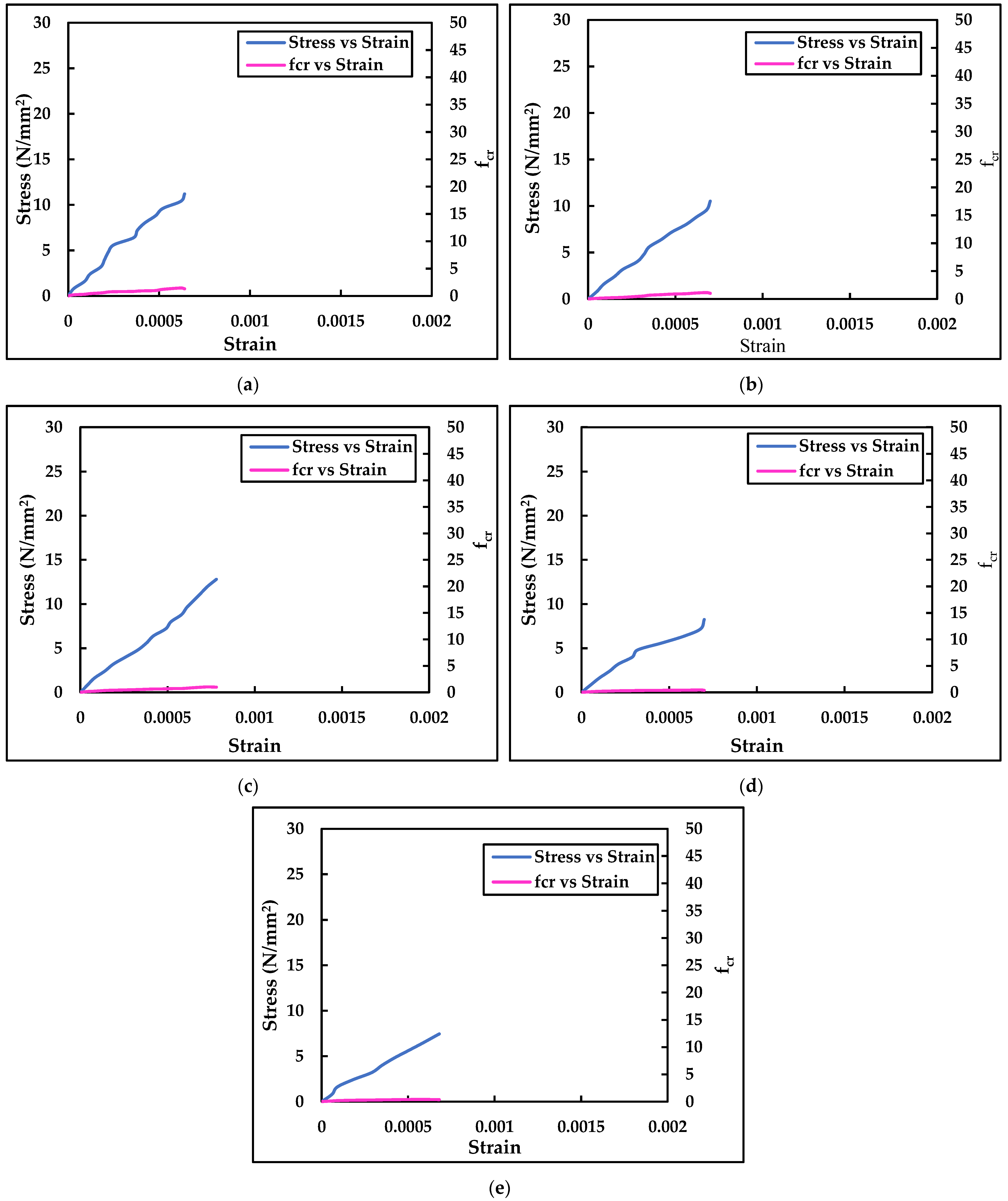
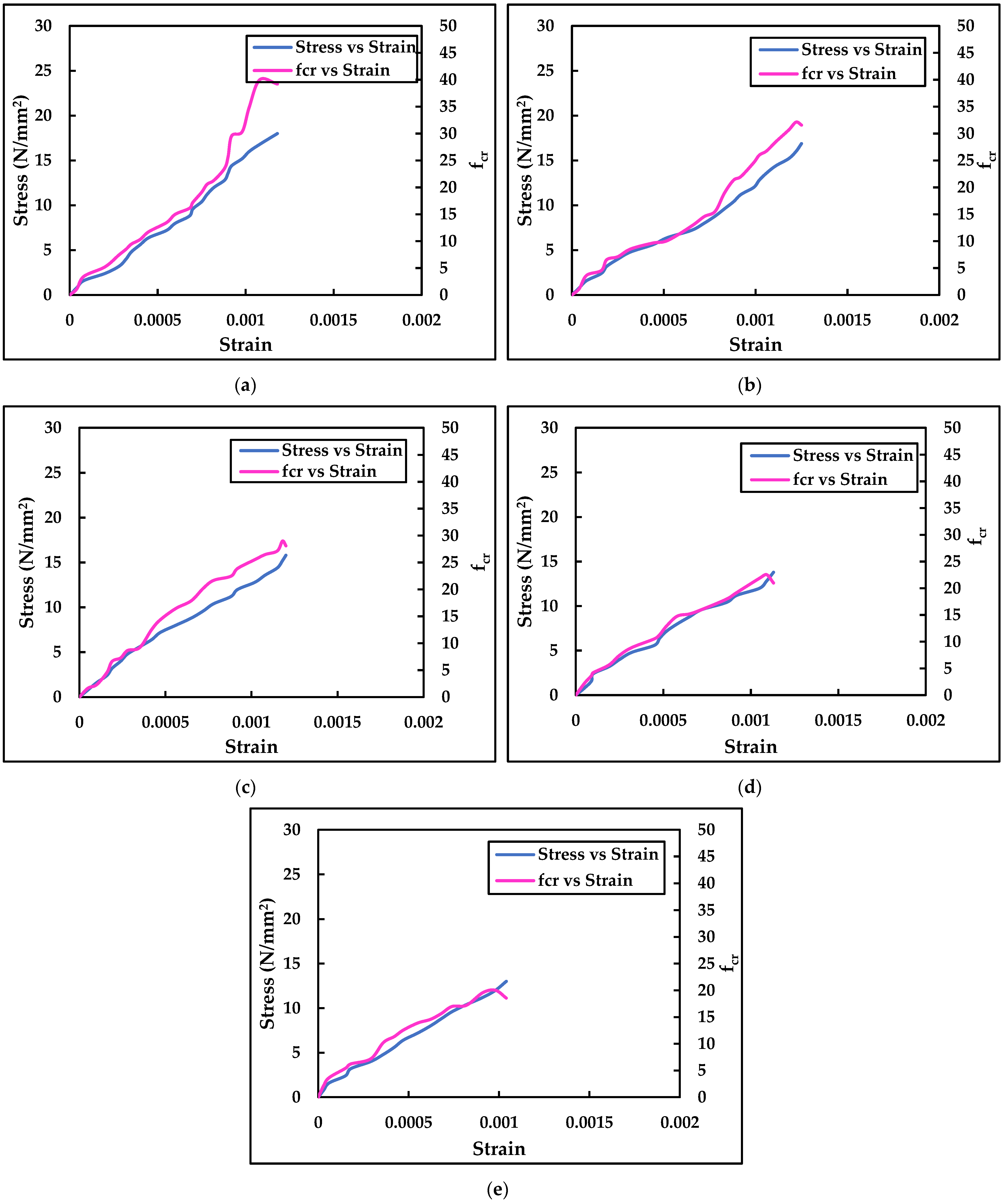
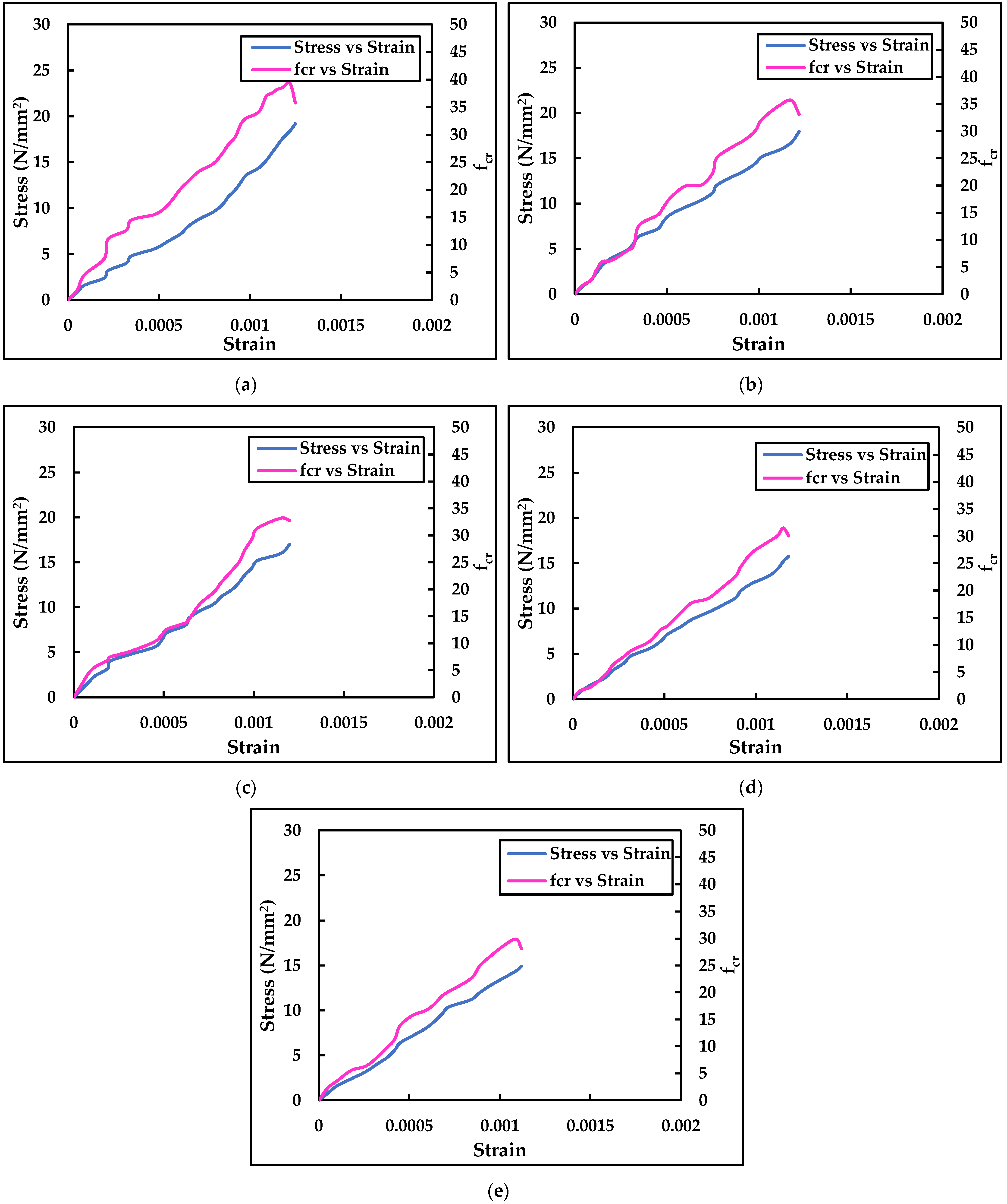
3.2. Electrical Measurements

3.2.1. Addition of Brass Fibres

Fractional change in electrical resistance (fcr) is defined as the change in its electrical resistance with respect to its initial resistance (ΔR/R). It is the change in the resistance of the specimen at each increment of loading with respect to its initial resistance before loading, i.e., zero loading. At 0.25% addition of brass fibre, fcr was observed at its maximum for both air curing and water curing. After 28 days of air curing, when compared to conventional mortar, the percentage increase in fcr was observed as 16.73%, 17.47%, 20.57%, 24.33%, and 21.63% for 0.10%, 0.15%, 0.20%, 0.20%, and 0.30% addition of brass fibres, respectively, as shown in Figure 9. After 28 days of water curing, when compared to conventional mortar, the percentage increase in fcr was observed to be 26.00%, 26.87%, 27.87%, 38.55%, and 35% for 0.10%, 0.15%, 0.20%, 0.20%, and 0.30% addition of brass fibres, respectively, as shown in Figure 10. Since the optimization of brass fibres was performed by electrical measurements, the optimised percentage was concluded as 0.25% volumetric ratio, whereas the compressive strength was observed to be high for 0.30% volumetric ratio. Similarly, while comparing air-cured specimen results with water-cured specimen results, it was observed that the water-cured specimens conduct more electricity, which yields better electrical resistance values. Hence, in water curing, the self-sensing ability of the mortar is high due to the entrapped moisture inside the specimen. The compressive strengths were also higher when the specimens were subjected to water curing.

3.2.2. Addition of Hybrid Brass and Carbon Fibres

When compared to traditional mortar, the significant rise in fcr was observed as 21.22%, 23.56%, and 25.99% for 95% brass fibre with 5% carbon fibre addition to the mortar mix for 7, 14, and 28 days of air curing, respectively. The percentage increase in fcr was observed as 21.47%, 23.33%, and 24.59% for 90% brass fibre, with 10% carbon fibre addition to the mortar mix in air curing with ordinary mortar. The percentage increase in fcr was observed as 22.47%, 23.33%, and 22.37% for 85% brass fibre with 15% carbon fibre addition to the mortar mix in air curing with ordinary mortar, as shown in Figure 11. The percentage increase in fcr was observed as 30.57%, 32.33%, and 37.99% for 95% brass fibre with 5% carbon fibre addition to mortar for 7, 14, and 28 days of water curing, respectively, with ordinary mortar. The percentage increase in fcr was observed as 32.73%, 30.57%, and 35.29% for 90% brass fibre, with 10% carbon fibre addition to the mortar mix in water curing with ordinary mortar. The percentage increase in fcr was observed as 33.33%, 32.57%, and 34.99% for 85% brass fibre, with 15% carbon fibre addition to the mortar mix in water curing with ordinary mortar, as shown in Figure 12.

3.3. Temperature Study

The conventional mortar, brass fibre added to mortar, and hybrid brass carbon fibre added to mortar were placed in the box furnace for various temperatures like room temperature, 200 °C, 400 °C, 600 °C, and 800 °C, as shown in Figure 13. The compressive strength of the conventional mortar was reduced by 6.07%, 11.79%, 26.34%, and 33.48% when subjected to 200 °C, 400 °C, 600 °C, and 800 °C, respectively. Similarly, the compressive strength of the brass fibre added mortar was reduced by 6.22%, 12.17%, 23.33%, and 27.72% when subjected to 200 °C, 400 °C, 600 °C, and 800 °C, respectively. The compressive strength of the hybrid brass carbon fibre added mortar was reduced by 6.46%, 11.35%, 17.71%, and 22.29% when subjected to 200 °C, 400 °C, 600 °C, and 800 °C, respectively, as shown in Figure 14.
As shown in Figure 15, the percentage decrease in maximum fractional change in electrical resistance values for conventional mortar is 20.69%, 29.65%, 68.97%, and 72.41% when subjected to 200 °C, 400 °C, 600 °C, and 800 °C, respectively. As shown in Figure 16, the percentage decrease in maximum fractional change in electrical resistance values for brass fibre added mortar is 19.7%, 27.55%, 43.60%, and 49.97% when subjected to 200 °C, 400 °C, 600 °C, and 800 °C, respectively. Figure 17 shows that when subjected to 200 °C, 400 °C, 600 °C, and 800 °C, the percentage decrease in maximum fractional change in electrical resistance values for hybrid brass carbon fibre added mortar are 9.33%, 15.56%, 19.84%, and 23.98%, respectively.

3.4. Micro-Characterization

The Scanning Electron Microscope (SEM) of raw brass fibres under different temperatures such as room temperature, 200 °C, 400 °C, 600 °C, and 800 °C is shown in Figure 18. The SEM image of brass fibre shows that its shape is irregular with different lengths and cross-sections. The surface of the brass fibre is observed to be rough and uneven, which results in better bonding of cement mortar. Due to this property, brass fibre provides better anchorage in the cement mortar matrix, as shown in Figure 19.
The Scanning Electron Microscope of raw brass fibres under different temperatures such as room temperature, 200 °C, 400 °C, 600 °C, and 800 °C is shown in Figure 20. Similarly, carbon fibres are hair-like materials with a uniform cross-section and length. Due to their microstructural property, carbon fibres are difficult to disperse in a cement mortar matrix. Hence, dispersion agents like methylcellulose are added to the cement mortar matrix for effective dispersion. Additionally, round silica fume particles are observed in brass fibre added to cement mortar and hybrid brass–carbon fibre added to cement mortar. The SEM images of carbon fibres at different temperatures showed that the surface texture of the carbon fibres changes as the temperature increases. At 600 °C, the fibres get burnt and the ash particles were seen on the fibre strands. At 800 °C, the fibres were mostly burnt, and hence only the ash particles were observed in the image.
Element analysis was performed through an Energy Dispersive Spectrometer (EDS) for the raw brass fibre at various elevated temperatures, as shown in Figure 21. Element analysis was performed to determine the changes occurring in the specimen’s elements when subjected to elevated temperatures. Copper, aluminium, and zinc are the major elements in a brass fibre sample at room temperature. At 200 °C, in addition to the major elements found in brass fibres at room temperature, nitrogen and oxygen were also found in the element analysis process. As the temperature increases, levels of copper found in the brass fibre sample are reduced and elements like nitrogen and oxygen are found. At elevated temperatures of 400 °C, 600 °C, and 800 °C, the presence of carbon, oxygen, and nitrogen was seen. These particles were the result of the burning of brass fibres. When the brass fibres were subjected to elevated temperatures, colour change was observed in the fibre samples. At room temperature, fibres were seen in a golden colour. The fibres were burnt and turned a dark brown colour at 800 °C. The colour changes gradually increased from golden to dark brown with an increase in temperature from room temperature to 800 °C.
Element analysis was performed through an Energy Dispersive Spectrometer (EDS) for the raw carbon fibre at various elevated temperatures, as shown in Figure 22. At room temperature, the two most abundant elements in a carbon fibre sample are carbon and oxygen. At 200 °C, in addition to the major elements found in carbon fibres at room temperature, nitrogen was also found in the element analysis process. At 600 °C, along with the conventional elements of iron, silicon, aluminium, and calcium, they were also found. Similarly, at 800 °C, iron, silicon, aluminium, and calcium elements were found in addition. At 400 °C, only carbon, oxygen, and nitrogen were found. The presence of silica, oxygen, calcium, and aluminium is due to the burning of carbon fibres into ash form since ash particles were found only at these two temperatures. When the carbon fibres were subjected to elevated temperatures, the carbon fibres started to burn. The majority of the fibre sample was burned at 600 °C, leaving one or two strands of carbon fibre unburned. At 800 °C, the entire carbon fibre sample was burned completely, and the ash was seen in the furnace.
X-ray powder diffraction (XRD) was conducted to determine the crystalline material in the mortar specimen. Since materials like silica fume, methylcellulose, superplasticizer, and fibres were added in addition to the conventional mortar, and XRD was carried out to determine the changes in the crystalline forms created in the mortar matrix. Materials such as silica fume and methyl cellulose have the ability to react with cement components and hence can form new crystalline forms that can affect the strength of the resulting mortar. The dicalcium silicate and tricalcium silicate (C2S and C3S) were observed to have higher peaks in brass fibre added cement mortar than in conventional mortar. Similarly, it was also observed to be higher when compared to hybrid brass carbon fibre-added cement mortar. Another crystalline material that was observed in high peaks was quartz (SiO2), as shown in Figure 23. The presence of high amounts of quartz in brass fibre added cement mortar and hybrid brass carbon fibre added cement mortar was due to the addition of silica fume in both these mortar mixes. These hydration compounds and quartz were likely responsible for improving the strength of the mortar mix by increasing its bonding strength. The addition of fibres to the conventional mortar results in better hydration and bonding between the mortar matrix, which is observed in the components.

4. Conclusions

Experiments on ordinary mortar, brass fibre added mortar, and hybrid fibre added mortar yielded the following results.
  • The addition of brass fibres to ordinary mortar enhanced the compressive strength of the mortar, and when carbon fibres were added to traditional mortar, together with brass fibres, the compressive strength was lower than when only brass fibres were added.
  • The presence of steel mesh in the mortar samples resulted in high compressive strength values in all the mortar mixes.
  • The addition of 0.25% brass fibres to the conventional mortar and the addition of 95% brass fibres, along with 5% carbon fibres, to the conventional mortar improved the piezo resistance.
  • Addition of hybrid brass and carbon fibres to the conventional mortar showed similar behaviour in electrical measurements when compared with brass fibre added mortar.
  • Under elevated temperatures, the compressive strength of the mortar decreases as the temperature increases. Similarly, when the temperature is increased, the fcr value also reduces in conventional mortar, as well as in a smart mortar.
  • In hybrid brass carbon fibres added to mortar cubes, the carbon fibres were not seen in the specimens placed at 800 °C as the carbon fibres turn into ash.
As a result, both carbon and brass fibres are capable of self-sensing and can be employed as conductive materials in cementitious composites. Even after exposing the specimens to elevated temperatures, the self-sensing ability of the mortar is retained. Hence, this smart mortar can also be used when exposed to fire.

Author Contributions

R.D.: Conducted the experiments; T.V. and S.K.S.: Supervised the research as well as the validation of results; R.D., T.V. and S.K.S.: Introduced the idea of self-sensing in this project, wrote, reviewed, and submitted the paper, and collaborated in and coordinated the research; T.V., S.K.S., B.G.A.G. and K.R.: Suggested and chose the journal for submission; R.D., T.V., S.K.S., B.G.A.G. and K.R.: Paper review and editing the final draft. All authors have read and agreed to the published version of the manuscript.

Funding

This research received no external funding.

Institutional Review Board Statement

Not applicable.

Informed Consent Statement

Not applicable.

Data Availability Statement

The data presented in this study are available on request from the corresponding author.

Conflicts of Interest

This manuscript has not been submitted to, nor is it under review by, another journal or other publishing venue. The authors have no affiliation with any organization with a direct or indirect financial interest in the subject matter discussed in the manuscript. The authors declare no conflict of interest.

References

  1. Han, B.; Ding, S.; Yu, X. Intrinsic self-sensing concrete and structures: A review. Measurement 2015, 59, 110–128. [Google Scholar] [CrossRef]
  2. Dong, W.; Li, W.; Tao, Z.; Wang, K. Piezoresistive properties of cement-based sensors: Review and perspective. Constr. Build. Mater. 2019, 203, 146–163. [Google Scholar] [CrossRef]
  3. Vipulanandan, C.; Mohammed, A. Smart cement modified with iron oxide nanoparticles to enhance the piezoresistive behavior and compressive strength for oil well applications. Smart Mater. Struct. 2015, 24, 125020. [Google Scholar] [CrossRef]
  4. Han, B.; Qiao, G.; Jiang, H. Piezoresistive response extraction for smart cement-based composites/sensors. J. Wuhan Univ. Technol. Sci. Ed. 2012, 27, 754–757. [Google Scholar] [CrossRef]
  5. Chen, M.; Gao, P.; Geng, F.; Zhang, L.; Liu, H. Mechanical and smart properties of carbon fiber and graphite conductive concrete for internal damage monitoring of structure. Constr. Build. Mater. 2017, 142, 320–327. [Google Scholar] [CrossRef]
  6. Han, B.; Ou, J. Embedded piezoresistive cement-based stress/strain sensor. Sens. Actuators A Phys. 2007, 138, 294–298. [Google Scholar] [CrossRef]
  7. Han, B.; Zhang, L.; Sun, S.; Yu, X.; Dong, X.; Wu, T.; Ou, J. Electrostatic self-assembled carbon nanotube/nano carbon black composite fillers reinforced cement-based materials with multifunctionality. Compos. Part A Appl. Sci. Manuf. 2015, 79, 103–115. [Google Scholar] [CrossRef]
  8. Monteiro, A.; Cachim, P.; Costa, P.M. Self-sensing piezoresistive cement composite loaded with carbon black particles. Cem. Concr. Compos. 2017, 81, 59–65. [Google Scholar] [CrossRef]
  9. Ding, Y.; Liu, G.; Hussain, A.; Pacheco-Torgal, F.; Zhang, Y. Effect of steel fiber and carbon black on the self-sensing ability of concrete cracks under bending. Constr. Build. Mater. 2019, 207, 630–639. [Google Scholar] [CrossRef]
  10. Jiang, Z.; Ozbulut, O.E.; Xing, G. Self-Sensing Characterization of GNP and carbon black filled cementitious composites. In Proceedings of the ASME 2019 Conference on Smart Materials, Adaptive Structures and Intelligent Systems, Louisville, KY, USA, 9–11 September 2019. [Google Scholar]
  11. Yıldırım, G.; Sarwary, M.H.; Al-Dahawi, A.; Öztürk, O.; Anıl, O.; Sahmaran, M. Piezoresistive behavior of CF-and CNT-based reinforced concrete beams subjected to static flexural loading: Shear failure investigation. Constr. Build. Mater. 2018, 168, 266–279. [Google Scholar] [CrossRef]
  12. Guan, X.C.; Han, B.; Tang, M.; Ou, J.P. Temperature and humidity variation of specific resistance of carbon fiber reinforced cement. In Proceedings of the Smart Structures and Materials 2005 Conference, San Diego, CA, USA, 17 May 2005; pp. 1–7. [Google Scholar]
  13. Borinaga-Treviño, R.; Orbe, A.; Canales, J.; Norambuena-Contreras, J. Experimental evaluation of cement mortars with recycled brass fibres from the electrical discharge machining process. Constr. Build. Mater. 2020, 246, 118522. [Google Scholar] [CrossRef]
  14. Borinaga-Treviño, R.; Orbe, A.; Canales, J.; Norambuena-Contreras, J. Thermal and mechanical properties of mortars reinforced with recycled brass fibres. Constr. Build. Mater. 2020, 284, 122832. [Google Scholar] [CrossRef]
  15. Sathyanarayanan, K.S.; Sridharan, N. Self Sensing Concrete using Carbon Fibre for Health Monitoring of Structures under Static loading. Indian J. Sci. Technol. 2016, 9, 1–5. [Google Scholar] [CrossRef]
  16. Sridharan, N.; Satyanarayanan, K.S. Smart concrete using carbon fibre for stress analysis of Structures under static loading. Int. J. Earth Sci. Eng. 2017, 10, 1045–1060. [Google Scholar]
  17. Liu, Q.; Wu, W.; Xiao, J.; Tian, Y.; Chen, J.; Singh, A. Correlation between damage evolution and resistivity reaction of concrete in-filled with graphene nanoplatelets. Constr. Build. Mater. 2019, 208, 482–491. [Google Scholar] [CrossRef]
  18. Ozbulut, O.E.; Jiang, Z.; Harris, D.K. Exploring scalable fabrication of self-sensing cementitious composites with graphene na-noplatelets. Smart Mater. Struct. 2018, 27, 115029. [Google Scholar] [CrossRef]
  19. Ding, S.; Ruan, Y.; Yu, X.; Han, B.; Ni, Y.-Q. Self-monitoring of smart concrete column incorporating CNT/NCB composite fillers modified cementitious sensors. Constr. Build. Mater. 2019, 201, 127–137. [Google Scholar] [CrossRef]
  20. D’Alessandro, A.; Rallini, M.; Ubertini, F.; Materazzi, A.L.; Kenny, J.M. Investigations on scalable fabrication procedures for self-sensing carbon nanotube cement-matrix composites for SHM applications. Cem. Concr. Compos. 2016, 65, 200–213. [Google Scholar] [CrossRef]
  21. Han, B.; Yu, X.; Kwon, E. A self-sensing carbon nanotube/cement composite for traffic monitoring. Nanotechnology 2009, 20, 445501. [Google Scholar] [CrossRef]
  22. Han, B.; Zhang, K.; Burnham, T.; Kwon, E.; Yu, X. Integration and road tests of a self-sensing CNT concrete pavement system for traffic detection. Smart Mater. Struct. 2013, 22, 015020. [Google Scholar] [CrossRef]
  23. Azhari, F.; Banthia, N. Cement-based sensors with carbon fibers and carbon nanotubes for piezoresistive sensing. Cem. Concr. Compos. 2012, 34, 866–873. [Google Scholar] [CrossRef]
  24. Meehan, D.G.; Wang, S.; Chung, D.D.L. Electrical-resistance-based sensing of impact damage in carbon fiber reinforced ce-ment-based materials. J. Intell. Mater. Syst. Struct. 2010, 21, 83–105. [Google Scholar] [CrossRef]
  25. Faneca, G.; Segura, I.; Torrents, J.; Aguado, A. Development of conductive cementitious materials using recycled carbon fibres. Cem. Concr. Compos. 2018, 92, 135–144. [Google Scholar] [CrossRef]
  26. Azhari, F.; Banthia, N. Carbon fiber-reinforced cementitious composites for tensile strain sensing. ACI Mater. J. 2017, 114, 129–136. [Google Scholar]
  27. Liu, B.; Zhang, X.; Ye, J.; Liu, X.; Deng, Z. Mechanical properties of hybrid fiber reinforced coral concrete. Case Stud. Constr. Mater. 2022, 16, e00865. [Google Scholar] [CrossRef]
  28. Zegardło, B. Heat-resistant concretes containing waste carbon fibers from the sailing industry and recycled ceramic aggregates. Case Stud. Constr. Mater. 2022, 16, e01084. [Google Scholar] [CrossRef]
  29. Chiarello, M.; Zinno, R. Electrical conductivity of self-monitoring CFRC. Cem. Concr. Compos. 2005, 27, 463–469. [Google Scholar] [CrossRef]
  30. Konsta-Gdoutos, M.S.; Aza, C.A. Self sensing carbon nanotube (CNT) and nanofiber (CNF) cementitious composites for real time damage assessment in smart structures. Cem. Concr. Compos. 2014, 53, 162–169. [Google Scholar] [CrossRef]
  31. Erdem, S.; Hanbay, S.; Blankson, M.A. Self-sensing damage assessment and image-based surface crack quantification of carbon nanofibre reinforced concrete. Constr. Build. Mater. 2017, 134, 520–529. [Google Scholar] [CrossRef]
  32. Wang, H.; Gao, X.; Wang, R. The influence of rheological parameters of cement paste on the dispersion of carbon nanofibers and self-sensing performance. Constr. Build. Mater. 2017, 134, 673–683. [Google Scholar] [CrossRef]
  33. Wang, H.; Gao, X.; Liu, J.; Ren, M.; Lu, A. Multi-functional properties of carbon nanofiber reinforced reactive powder concrete. Constr. Build. Mater. 2018, 187, 699–707. [Google Scholar] [CrossRef]
  34. Wang, H.; Shen, J.; Liu, J.; Lu, S.; He, G. Influence of carbon nanofiber content and sodium chloride solution on the stability of resistance and the following self-sensing performance of carbon nanofiber cement paste. Case Stud. Constr. Mater. 2019, 11, e00247. [Google Scholar] [CrossRef]
  35. Liu, Q.; Xu, Q.; Yu, Q.; Gao, R.; Tong, T. Experimental investigation on mechanical and piezoresistive properties of cementitious materials containing graphene and graphene oxide nanoplatelets. Constr. Build. Mater. 2016, 127, 565–576. [Google Scholar] [CrossRef]
  36. Sassani, A.; Ceylan, H.; Kim, S.; Arabzadeh, A.; Taylor, P.C.; Gopalakrishnan, K. Development of Carbon Fiber-modified Electrically Conductive Concrete for Implementation in Des Moines International Airport. Case Stud. Constr. Mater. 2018, 8, 277–291. [Google Scholar] [CrossRef]
  37. Ram Kumar, V.D.; Thirumurugan, K.S. Satyanarayanan. Experimental study on optimization of smart mortar with the addition of brass fibres. Mater. Today Proc. 2022, 50, 388–393. [Google Scholar] [CrossRef]
  38. Sun, S.; Han, B.; Jiang, S.; Yu, X.; Wang, Y.; Li, H.; Ou, J. Nano graphite platelets-enabled piezoresistive cementitious composites for structural health monitoring. Constr. Build. Mater. 2017, 136, 314–328. [Google Scholar] [CrossRef] [Green Version]
  39. Liu, X.; Nie, Z.; Wu, S.; Wang, C. Self-monitoring application of conductive asphalt concrete under indirect tensile deformation. Case Stud. Constr. Mater. 2015, 3, 70–77. [Google Scholar] [CrossRef] [Green Version]
  40. Teomete, E.; Kocyigit, O.I. Tensile strain sensitivity of steel fiber reinforced cement matrix composites tested by split tensile test. Constr. Build. Mater. 2013, 47, 962–968. [Google Scholar] [CrossRef]
  41. Wen, S.; Chung, D.D.L. A comparative study of steel- and carbon-fibre cement as piezoresistive strain sensors. Adv. Cem. Res. 2003, 15, 119–128. [Google Scholar] [CrossRef]
  42. Chen, B.; Wu, K.; Yao, W. Conductivity of carbon fiber reinforced cement-based composites. Cem. Concr. Compos. 2004, 26, 291–297. [Google Scholar] [CrossRef]
  43. Dongyu, X.; Sourav, B.; Yanbing, W.; Shifeng, H.; Xin, C. Temperature and loading effects of embedded smart piezoelectric sensor for health monitoring of concrete structures. Const. Build. Mater. 2015, 76, 87–193. [Google Scholar]
  44. Baeza, F.J.; Vilaplana, J.L.; Galao, O.; Garcés, P. Sensitivity study of self-sensing strain capacity of alkali-activated blast furnace slag reinforced with carbon fibres. Hormigón Y Acero 2018, 69, 243–250. [Google Scholar]
  45. Banthia, N.; Djeridane, S.; Pigeon, M. Electrical resistivity of carbon and steel micro-fiber reinforced cements. Cem. Concr. Res. 1992, 22, 804–814. [Google Scholar] [CrossRef]
  46. Teomete, E. Transverse strain sensitivity of steel fiber reinforced cement composites tested by compression and split tensile tests. Constr. Build. Mater. 2014, 55, 136–145. [Google Scholar] [CrossRef]
  47. Demircilioğlu, E.; Teomete, E.; Ozbulut, O.E. Characterization of smart brass fiber reinforced concrete under various loading conditions. Constr. Build. Mater. 2020, 265, 120411. [Google Scholar] [CrossRef]
  48. Teomete, E. The effect of temperature and moisture on electrical resistance, strain sensitivity and crack sensitivity of steel fiber reinforced smart cement composite. Smart Mater. Struct. 2016, 25, 075024. [Google Scholar] [CrossRef]
  49. Galao, O.; Baeza, F.J.; Zornoza, E.; Garcés, P. Carbon Nanofiber Cement Sensors to Detect Strain and Damage of Concrete Specimens Under Compression. Nanomaterials 2017, 7, 413. [Google Scholar] [CrossRef] [PubMed] [Green Version]
  50. Demircilioglu, E.; Teomete, E.; Schlangen, E.; Baeza, F.J. Temperature and moisture effects on electrical resistance and strain sensitivity of smart concrete. Constr. Build. Mater. 2019, 224, 420–427. [Google Scholar] [CrossRef]
  51. Apuzzo, A.; Barretta, R.; Fabbrocino, F.; Faghidian, S.A.; Luciano, R.; De Sciarra, F.M. Axial and Torsional Free Vibrations of Elastic Nano-Beams by Stress-Driven Two-Phase Elasticity. J. Appl. Comput. Mech. 2019, 5, 402–413. [Google Scholar] [CrossRef]
  52. Boparai, K.S.; Singh, R.; Fabbrocino, F.; Fraternali, F. Thermal characterization of recycled polymer for additive manufacturing applications. Compos. Part B Eng. 2016, 106, 42–47. [Google Scholar] [CrossRef]
  53. Fabbrocino, F.; Farina, I.; Amendola, A.; Feo, L.; Fraternali, F. Optimal design and additive manufacturing of novel reinforcing elements for composite materials. In Proceedings of the ECCOMAS Congress 2016—European Congress on Computational Methods in Applied Sciences and Engineering, Crete Island, Greece, 5–10 June 2016; pp. 1–16. [Google Scholar] [CrossRef] [Green Version]
  54. Rajamony Laila, L.; Gurupatham, B.G.A.; Roy, K.B.P.; Lim, J. Effect of super absorbent polymer on microstructural and mechanical properties of concrete blends using granite pulver. Struct. Concr. 2021, 22, E898–E915. [Google Scholar] [CrossRef]
  55. Rajamony Laila, L.; Gurupatham, B.G.A.; Roy, K.; Lim, J.B.P. Influence of super absorbent polymer on mechanical, rheological, durability, and microstructural properties of self-compacting concrete using non-biodegradable granite pulver. Struct. Concr. 2021, 22, E1093–E1116. [Google Scholar] [CrossRef]
  56. Lowe, D.; Roy, K.; Das, R.; Clifton, C.G.; Lim, J.B. Full scale experiments on splitting behaviour of concrete slabs in steel concrete composite beams with shear stud connection. Structures 2020, 23, 126–138. [Google Scholar] [CrossRef]
  57. Madan, C.S.; Munuswamy, S.; Joanna, P.S.; Gurupatham, B.G.A.; Roy, K. Comparison of the Flexural Behavior of High-Volume Fly Ash Based Concrete Slab Reinforced with GFRP Bars and Steel Bars. J. Compos. Sci. 2022, 6, 157. [Google Scholar] [CrossRef]
  58. Madan, C.S.; Panchapakesan, K.; Anil Reddy, P.V.; Joanna, P.S.; Rooby, J.; Gurupatham, B.G.A.; Roy, K. Influence on the Flexural Behaviour of High-Volume Fly-Ash-Based Concrete Slab Reinforced with Sustainable Glass-Fibre-Reinforced Polymer Sheets. J. Compos. Sci. 2022, 6, 169. [Google Scholar] [CrossRef]
  59. Sivanantham, P.; Gurupatham, B.G.A.; Roy, K.; Rajendiran, K.; Pugazhlendi, D. Plastic Hinge Length Mechanism of Steel-Fiber-Reinforced Concrete Slab under Repeated Loading. J. Compos. Sci. 2022, 6, 164. [Google Scholar] [CrossRef]
  60. Roy, K.; Akhtar, A.; Sachdev, S.; Hsu, M.; Lim, J.; Sarmah, A. Development and characterization of novel biochar-mortar composite utilizing waste derived pyrolysis biochar. Int. J. Sci. Eng. Res. 2017, 8, 1912–1919. [Google Scholar]
Figure 1. Picture of the brass fibres.
Jcs 06 00208 g001
Figure 2. Picture of the carbon fibres.
Jcs 06 00208 g002
Figure 3. Cubical specimen cast.
Jcs 06 00208 g003
Figure 4. Hybrid fibre added mortar cube specimen placed with steel mesh.
Jcs 06 00208 g004
Figure 5. The four-probe method’s circuit diagram.
Jcs 06 00208 g005
Figure 6. Testing of cubes.
Jcs 06 00208 g006
Figure 7. Graphical illustration of mortar cube compressive strength with brass fibres added. (a) Air curing; (b) Water curing.
Jcs 06 00208 g007aJcs 06 00208 g007b
Figure 8. Graphical illustration of mortar cube compressive strength with hybrid fibres added. (a) Air curing; (b) Water curing.
Jcs 06 00208 g008aJcs 06 00208 g008b
Figure 9. Graphical illustration of stress vs. strain and fcr vs. strain under 28 days of air curing. (a) Conventional mortar cube; (b) 0.10% brass fibre added mortar cube; (c) 0.15% brass fibre added mortar cube; (d) 0.20% brass fibre added mortar cube (e) 0.25% brass fibre added mortar cube; (f) 0.30% brass fibre added mortar cube.
Jcs 06 00208 g009aJcs 06 00208 g009b
Figure 10. Graphical illustration of stress vs. strain and fcr vs. strain under 28 days of water curing. (a) Conventional mortar cube; (b) 0.10% brass fibre added mortar cube; (c) 0.15% brass fibre added mortar cube; (d) 0.20% brass fibre added mortar; (e) 0.25% brass fibre added mortar cube; (f) 0.30% brass fibre added mortar cube.
Jcs 06 00208 g010aJcs 06 00208 g010b
Figure 11. Graphical illustration of stress vs. strain and fcr vs. strain after 28 days of air curing. (a) 95% brass fibre with 5% carbon fibre addition; (b) 90% brass fibre with 10% carbon fibre addition; (c) 85% brass fibre with 15% carbon fibre addition.
Jcs 06 00208 g011
Figure 12. Graphical illustration of stress vs. strain and fcr vs. strain after 28 days of water curing. (a) 95% brass fibre with 5% carbon fibre addition; (b) 90% brass fibre with 10% carbon fibre addition; (c) 85% brass fibre with 15% carbon fibre addition.
Jcs 06 00208 g012
Figure 13. Specimens placed in the box furnace.
Jcs 06 00208 g013
Figure 14. Graphical illustration of compressive strength values of conventional mortar cube subjected to elevated temperatures.
Jcs 06 00208 g014
Figure 15. Graphical illustration of stress vs. strain and fcr vs. strain for conventional mortar cube after 28 days of water curing subjected to elevated temperatures. (a) Room temperature; (b) 200 °C; (c) 400 °C; (d) 600 °C; (e) 800 °C.
Jcs 06 00208 g015
Figure 16. Graphical illustration of stress vs. strain and fcr vs. strain for brass fibre added mortar cube after 28 days of water curing subjected to elevated temperatures. (a) Room temperature; (b) 200 °C; (c) 400 °C; (d) 600 °C; (e) 800 °C.
Jcs 06 00208 g016
Figure 17. Graphical illustration of stress vs. strain and fcr vs. strain for hybrid brass carbon fibre added mortar cube after 28 days of water curing subjected to elevated temperatures. (a) Room temperature; (b) 200 °C; (c) 400 °C; (d) 600 °C; (e) 800 °C.
Jcs 06 00208 g017
Figure 18. SEM Images of raw brass fibre subjected to different temperatures. (a) Room temperature; (b) 200 °C; (c) 400 °C; (d) 600 °C; (e) 800 °C.
Jcs 06 00208 g018aJcs 06 00208 g018b
Figure 19. SEM images of the cement mortar. (a) Conventional mortar; (b) Brass fibre added mortar; (c) Brass–carbon hybrid fibres added mortar.
Jcs 06 00208 g019
Figure 20. SEM Images of raw carbon fibre subjected to different temperatures. (a) Room temperature; (b) 200 °C; (c) 400 °C; (d) 600 °C; (e) 800 °C.
Jcs 06 00208 g020aJcs 06 00208 g020b
Figure 21. EDS Results of brass fibre subjected to elevated temperatures. (a) Room temperature; (b) 200 °C; (c) 400 °C; (d) 600 °C; (e) 800 °C.
Jcs 06 00208 g021aJcs 06 00208 g021b
Figure 22. EDS results of carbon fibres subjected to elevated temperatures. (a) Room temperature; (b) 200 °C; (c) 400 °C; (d) 600 °C; (e) 800 °C.
Jcs 06 00208 g022
Figure 23. XRD results of mortars. (a) Conventional mortar; (b) Brass fibre added mortar; (c) Brass–carbon hybrid fibres added mortar.
Jcs 06 00208 g023
Publisher’s Note: MDPI stays neutral with regard to jurisdictional claims in published maps and institutional affiliations.

