External Field Assisted Freeze Casting
by
 , , and
Pooya Niksiar
1 ,
,
Frances Y. Su
2,
Michael B. Frank
2,
Taylor A. Ogden
3,
Steven E. Naleway
3,
Marc A. Meyers
2,4,
Joanna McKittrick
2,5 and
Michael M. Porter
1,* 1
Department of Mechanical Engineering, Clemson University, Clemson, SC 29634, USA
2
Materials Science and Engineering Program, University of California, La Jolla, CA 92093, USA
3
Department of Mechanical Engineering, University of Utah, Salt Lake City, UT 84112, USA
4
Department of NanoEngineering, University of California, San Diego, La Jolla, CA 92093, USA
5
Department of Mechanical and Aerospace Engineering, University of California, La Jolla, CA 92093, USA
*
Author to whom correspondence should be addressed.
Ceramics 2019, 2(1), 208-234; https://0-doi-org.brum.beds.ac.uk/10.3390/ceramics2010018
Submission received: 6 February 2019
/
Revised: 6 March 2019
/
Accepted: 15 March 2019
/
Published: 24 March 2019
(This article belongs to the Special Issue Ice-Templated and Freeze-Cast Ceramics)
Abstract
:Freeze casting under external fields (magnetic, electric, or acoustic) produces porous materials having local, regional, and global microstructural order in specific directions. In freeze casting, porosity is typically formed by the directional solidification of a liquid colloidal suspension. Adding external fields to the process allows for structured nucleation of ice and manipulation of particles during solidification. External control over the distribution of particles is governed by a competition of forces between constitutional supercooling and electromagnetism or acoustic radiation. Here, we review studies that apply external fields to create porous ceramics with different microstructural patterns, gradients, and anisotropic alignments. The resulting materials possess distinct gradient, core–shell, ring, helical, or long-range alignment and enhanced anisotropic mechanical properties.
1. Introduction
Porosity in ceramics offers many potential advantages, making them lightweight, ideal for filtration and insulation [1,2], useful in tissue engineering [3,4], high-performance structural applications [5], catalysis [6], gas distributors, fuel cells and batteries [7,8]. Common processing methods to fabricate porous synthetic materials include template replication [9,10], direct foaming [11,12], 3D-printing [13,14], sol-gel methods [15,16] or electrospinning [17]. All of these processing routes have varying limitations, including a narrow range of pore characteristics [18]; difficult removal of pore-forming agents and binders [19,20]; costly, intricate and high pressure components [21]; additive toxicity, long drying times and troublesome polymerization reactions [22,23]; the presence of impurities [24,25]; and shrinkage and drying stresses [26,27]. Freeze casting is a relatively simple alternative that overcomes many of these limitations for fabricating porous anisotropic ceramics [28,29,30], polymers [31,32], metals [33,34] or composites [35,36], often exhibiting high compressive properties [37]. This method has potential applications in cryobiology [38], remediation of contaminated media [39,40], chemical analyses [41], liquid chromatography [42], energy storage [43,44], photocatalysis [45,46], sensors [47,48], pharmaceuticals [49] and the food industry [50,51].
Figure 1a illustrates the freeze casting (and post-processing) of porous ceramics. In this method, ceramic particles are mixed with a liquid (e.g., water) and then solidified directionally [37,52]. During freezing, ice columns grow into the form of lamellae, pushing away particles from their path [41,53]. Rejected particles are trapped between ice lamellae, forming particulate ceramic columns [54,55,56]. Then, the frozen solid is lyophilized to remove the ice, and sintered to partially densify and strengthen the porous material [57,58]. In the initial slurry, a binder and dispersant are also usually added [59]. The binder acts as a “glue” to prevent collapse of the green body, whereas the dispersant prevents aggregation of ceramic particles to ensure homogeneity [60]; other chemical additives are also sometimes used to prevent agglomeration of the binder/dispersant molecules and/or change the slurry chemistry [61]. Adjustments of the slurry composition have been shown to produce a variety of pore morphologies, from finely spaced lamellae (~1 µm) to large circular pores (~100 µm) [62,63].
Scaffolds made by freeze casting are generally stronger and stiffer in the solidification direction than in the transverse direction. Figure 1b shows representative stress–strain curves of a freeze cast scaffold compressed in these directions. Its mechanical properties are dependent on its microstructural architectures, which in this case are anisotropic, exhibiting greater long-range order in the solidification direction [59,64,65]. Two primary microstructural features are responsible for this directional disparity in strength and stiffness: lamellar walls and transverse bridges. Figure 1c,d illustrates these features on an electron micrograph of a TiO2 scaffold freeze cast at a cooling rate of 10 °C/min (after sintering at 1200 °C) [65]. Lamellar walls, formed by entrapped particles between two adjacent progressing ice columns, constitute the main load-bearing structures and exhibit compressive failure by buckling [65]. Bridges, on the other hand, are formed by the fusion of secondary dendrites or engulfed particles [60,64] and connect adjacent walls, preventing buckling [65], and, in some cases, bear (transverse) compressive loads [64].
Several approaches to modify the transverse microstructures of freeze cast scaffolds have been reported, including cold-surface patterning [66], freezing under flow [35,67], bidirectional freezing [68,69], radial freezing [70,71] and external field alignment [5,64,65,72,73,74,75,76,77,78,79,80,81,82]. The former four methods rely on the physical manipulation of a freezing suspension [35,66,68,69,70,71]. In the latter, external magnetic, electric, or acoustic fields are applied for remote control of the colloidal suspensions during solidification. In these methods, the liquid (e.g., water) and/or solids (e.g., charged or magnetized particles) are manipulated by the fields, which can vary by state (static versus alternating/oscillating), orientation, strength, and gradient. Because water is a polar, diamagnetic material, strong electric and magnetic fields can also change the molecular structure and properties of water [83,84], which can lead to the formation of different pore morphologies and orientations. Likewise, ultrasound waves can also promote ice nucleation and subsequent crystallization processes [85]. However, in the presence of relatively weak fields, the effects on particles suspended in water tend to dominate, leading to particle clustering, chaining, attraction, or alignment. By changing the particle concentration, morphology, electromagnetic properties, and slurry chemistry, different wall and bridge alignments and gradient-like patterns can be realized [73,76,80], which have been shown to enhance the transverse compressive properties of freeze cast scaffolds [64,76].
In magnetic freeze casting, weak fields (<1 T) are usually employed to directly manipulate nano-/micro-particles in a liquid slurry [64,76,78]. In contrast, electric and acoustic fields applied to the freeze casting process are usually very high (up to 150 kV/m and >900 kHz, respectively) [82,86]. In all cases, external fields are convenient tools to remotely control the microstructural patterns of freeze cast materials producing minimal interference with the slurry composition. Similarly, external fields to remotely manipulate matter have many other uses. Magnetic fields have also been used in other applications, such as high gradient magnetic field separators [87,88], slip casting of complex shaped ceramic parts with programmable microstructures [89], and stereolithography (SLA) and direct ink writing (DIW) to align reinforcing particles while 3D-printing [90,91]. Electric fields have also found applications in the characterization and fabrication of artificial tissues [92], the food industry [85] and colloidal assembly [93]. Acoustic fields have been utilized as particulate pollution removers [94], for acoustic levitation through ultrasound directed self-assembly [95], surface-tension-dominated fluid dynamics [96] and drug delivery [97].
In this review, we highlight important aspects of external field assisted freeze casting, focusing on the theory and experimental results. In Section 2, we explain constitutional supercooling, which is due to freezing point depression caused by premelting, curvature effects, and the external fields. In Section 3, the dominant forces exerted on particles during freeze casting under external fields are introduced. Finally, in Section 4, we review experimental observations made to date on freeze casting under external electric, magnetic, and acoustic fields.
2. Constitutional Supercooling
When a liquid, or slurry of colloidal particles, contacts a freezing surface, a temperature gradient forms close to the cold surface, leading to the directional growth of ice (or other solvent crystals) [98]. At slow freezing velocities, particles and solute molecules are repelled from the ice front and agglomerate along a planar liquid–solid interface [99,100]. At faster freezing velocities, thermo-morphological instabilities cause lamellar or dendritic layers of ice to form at the interface [101], a phenomenon reminiscent of directional solidification in binary alloys [102,103]. Figure 2a compares planar and layered ice growth. The morphology of these layers (lamellar versus dendritic) depends on the freezing velocity [104,105] as well as the particle/solute concentration in the slurry [106,107,108]. At the liquid–solid interface, particle agglomeration depresses the freezing point of the suspension, similar to how salting is used to melt ice in winter [109]. Assuming a linear temperature gradient in the slurry, particles/solute decrease the chemical potential of the solvent, lowering its freezing point (see Figure 2b) [101,109]. This is known as constitutional supercooling—i.e., “supercooling” that results from adding “constituents” to a solution. In this metastable condition, perturbations at the liquid–solid interface cause ice to grow in the form of lamellae [110], while, in the absence of supercooling, perturbations melt back into the planar interface [110,111,112]. In general, solute-driven supercooling, due to the presence of additives, tends to be stronger than particle-driven supercooling [111,113,114].
Freezing point depression by supercooling at the interface is due to premelting, curvature effects and the effect of external fields (i.e., magnetic, electric, and acoustic). Premelting is the existence of a thin layer of liquid (2–10 nm [115]) between ice and foreign material below the bulk melting temperature (e.g., 0 °C for water) [116,117,118]. The slipperiness of ice, for example, is due to this premelted layer [119]. It occurs due to van der Waals interactions [120,121] between the ice and foreign material molecules at the surface. A mismatch of atomic spacing at the ice–particle interface causes stress in the substrate (i.e., particle) near the interface so that energy is stored in the substrate. Introducing a liquid layer between the ice and particle relaxes these stresses and decreases the free energy of the system [122]. To explain, in the case that ice is in direct contact with a particle, the free energy of the solid–particle (ice–particle) interface is . However, if a layer of liquid intervenes between the ice and particle, then the free energy of the interface is (), where and are the liquid–solid (water–ice) and liquid–particle (water–particle) free energies. For many materials, it happens that:
or
where the free energy of a wetted interface is less than that of a dry interface [123], and premelting occurs (see Figure 2c). An interesting phenomenon in the premelted layer is a pressure difference that exists between the ice and premelted layer. Ice and water are at equilibrium at 0 °C and 1 atm. However, for temperatures below the melting point, the pressures of liquid water (the premelted layer) and ice are different at equilibrium. This pressure difference is given by [124]:
where is the premelt pressure, is the ice pressure, is latent heat of melting, is the liquid density, is the melting temperature, and is the actual temperature. The pressure of the premelted layer is less at lower temperatures due to a phenomenon called cryosuction [125,126,127], causing the premelted layer to migrate from higher to lower temperature [121,128] (a phenomenon responsible for frost heaving in soil [127]).
Another reason for freezing point depression is interfacial curvature effects. When an ice front approaches a particle, its planar interface is deformed (see Figure 2c). According to the Young–Laplace equation, there is a pressure difference at the curved interface, which results in a lower freezing point (i.e., the Gibbs–Thompson effect [129,130,131]). Therefore, the slurry temperature at the interface is given by [132]:
where is the mean curvature, is the surface tension between the ice and water, is the latent heat of melting, is the density of ice, is the melting temperature, is the premelted layer thickness, is a length scale proportional to the interaction strength, and the exponent depends on the type of intermolecular interactions [130,132,133,134]. The second term on the right-hand side is due to the curvature effect, while the third term is due to premelting effects.
External fields can also alter the freezing point of water because it is a strongly polar, weakly diamagnetic molecule [135]. In its liquid state, H2O molecules form loose networks of ring-like structures of various shape and size [135]. To freeze, the water molecules must rearrange to initiate the nucleation of ice crystals [136]. In the absence of any nucleating agents (homogeneous nucleation), water becomes supercooled and can exist as a liquid, as low as –41 °C [137]. However, freezing is often initiated by foreign substrates (heterogeneous nucleation), where water molecules aggregate onto a substrate surface, forming ice nuclei [138]. In freeze casting, for instance, the initial cold surface and dispersed particles typically act as ice nucleators [139,140].
External fields can change the morphology of hydrogen-bonded chains formed in supercooled water [83,84]. By decreasing the temperature under an external field, these H2O chains (often in the form of rings) lead to structured ice nucleation events [141]. Under static magnetic fields, hydrogen-bonded rings are thought to become smaller, leading to decreased viscosity and finer crystal growth [84,141]. However, the addition of magnetite (Fe3O4) to pure water (as in magnetic freeze casting) promotes ice nucleation since the magnetite particles act as nucleation sites. In contrast, oscillating magnetic fields disrupt the ability of water molecules to nucleate on the surface of disturbed magnetite, thereby promoting supercooling [142,143]. Under electric fields, the rings become larger, leading to increased viscosity and aligned crystal growth [83,141]. This promotes nucleation and increases the freezing point temperature, a process known as electrofreezing [144]. Under properly aligned acoustic fields, a standing ultrasound wave field can form where the acoustic radiation force creates a standing pressure wave [145,146,147]. This standing pressure wave results in distinct nodes of high and low pressure, which can often be visually observed as water molecules are forced to low pressure regions of the standing wave.
For comparison, Figure 3 shows electron micrographs of scaffolds formed by freezing ceramic colloidal particles under different external field conditions [82,86]. As seen, magnetic fields tend to decrease the pore size, due to the formation of smaller ice crystals, compared to a non-magnetized slurry. In contrast, electric fields tend to align and increase pore size. Understanding pressure waves, acoustic fields cause particles to migrate to low pressure regions, creating alternating zones of high and low particle concentrations, leading to high and low density bands.
3. Dominant Forces
3.1. Forces Exerted During Solidification
Historically, two approaches explain the repulsive forces between a particle and the ice front. Uhlmann et al. [148], Bolling and Cisse [149], and Gilpin [115,150] proposed that the presence of a particle close to an ice interface lowers the chemical potential of the liquid intervening between the particle and ice, causing flow of liquid from outside this region to push the particle away from the interface. On the other hand, Chernov et al. [151] recognized that intermolecular interactions are responsible; these include van der Waals and electrostatic forces [54,120]. When an ice front approaches a particle, these intermolecular interactions become dominant at ~10−8–10−7 m, resulting in a net repulsive force pushing the particle away from the interface (see Figure 2c). For non-retarded van der Waals interactions, the repulsive force per unit area is given by [54,152]:
where is the Hamaker constant for the interaction between ice and a particle with the premelting layer intervening, and are the density and melting latent heat of ice, is the thickness of the premelted layer, and is a length proportional to the interaction strength [54]. This repulsive force is also known as the thermomolecular pressure [153,154], or disjoining pressure, in the context of wetting [155,156]. Integrating over the deformed interface will yield the total repulsive force on the particle [132]:
where is the particle radius and is the upper limit of film thickness between the ice and particle, which is much greater than the thickness of the premelted layer beneath the particle. The pressure distributed around the particle also causes a resistive force, known as the lubrication force [54,157]:
where is the liquid viscosity, is the particle velocity, and is the thickness of the film between the particle and ice front. At slow freezing velocities, the repulsive force is dominant and particles are repelled from the interface. At faster freezing velocities, the resistive force is dominant and the particle–ice gap decreases, such that the flow of water is diminished and the particle is trapped by the ice front. Generally, in freeze cast scaffolds, repelled particles form lamellar walls, whereas trapped particles form transverse bridges (see Figure 1c,d). Note, however, that most studies on these forces focus on the case of dilute solutions. In slurries with higher particle concentrations, there are forces from neighboring particles in addition to the repulsive and resistive forces from the ice front [75,158]. In such cases, the mode of instability changes from Mullins–Serkerka to local split and global split modes [111,159].
3.2. Forces Exerted by External Fields
3.2.1. Magnetic Force and Torque
When a magnetic particle is placed in a magnetic field, a magnetic torque is exerted on the particle. This torque is given by:
where is the magnetic moment and is the magnetic field. This magnetic torque aligns particles with anisotropic geometries or magnetic properties with the field direction [160]. On the other hand, if an applied magnetic field is non-uniform, a field gradient forms and exerts a force on magnetic particles. This force is given by:
where is the del operator. For a particle of radius and magnetic susceptibility suspended in a medium of magnetic susceptibility , the force exerted on the particle is [161,162]:
where is vacuum permeability and is the magnetic field from Ampere’s law, defined as [163,164].
3.2.2 Electric Force and Torque
Similar to magnetic fields, electric fields exert torque on polarized particles causing them to align with the field direction, given by:
where is the dipole moment and is the electric field. Under non-uniform electric fields, however, the force on a particle is given by [93,162]:
where is vacuum permittivity, is the effective dielectric constant, and is the particle volume.
3.2.3 Acoustic Force
Acoustic, ultrasound pressure waves can also orient and position particles. This process, known as ultrasound directed self-assembly has been shown to effectively align a variety of colloidal particles and organisms, including bacteria cells and carbon nanotubes [165,166,167]. When radiated pressure waves (i.e., sound waves) are absorbed or reflected by particles suspended in water, they exert a force on the particles [147]. At specific frequencies, radiated and reflected waves superimpose and cancel each other out, producing pressure nodes [162]. At other distances, these waves strengthen each other and create anti-nodes. As a result, standing waves form in the medium with high and low pressure regions. This standing wave creates an acoustic radiation potential given by [82]:
where is the particle radius; and are the liquid medium and particle sound propagation velocities, respectively; and and are the densities of the medium and particle, respectively. Further, is the wave number, where is the wavelength of a standing ultrasound wave field; and are the zeroth and first order Bessel functions, respectively; and is the time-averaged pressure where is the amplitude of the standing wave field. The acoustic radiation force is found by taking the negative gradient of the acoustic potential:
This force pushes suspended particles toward the minimum of acoustic radiation potential, causing agglomerations of particles in those areas.
3.3. Resistive Forces
In all cases, external fields must compete with thermal, gravitational, and viscous forces to align or position suspended particles. The magnitudes of all mentioned forces (Equations (10), (12) and (14)) depend on particle size and geometry. As an example, Figure 4 shows different particle behaviors under external magnetic fields. For smaller particles, thermal energies (Brownian motion) are usually stronger than the magnetic torque and no specific alignment is observed, while for largely anisotropic particles, gravitational forces are dominant and particles tend to align horizontally. Thus, particles within specific size ranges are desired for external field alignment [168]. Viscous forces are also important in dynamic systems where particles move/rotate at higher velocities. For example, Erb et al. [169] applied rotating magnetic fields to a solution of surface-magnetized platelets suspended in a fluid. They observed a synced rotation of platelets at lower frequencies but found that viscous forces dominate at higher frequencies causing the platelets to align parallel to the plane of rotation (see Figure 4a,d). Other mechanisms of patterning/alignment include particle clustering and chaining [170,171]. These are driven by global attraction/repulsion of particles under gradient fields or local attraction between neighboring particles under near-uniform fields. The resulting distributions of two-phase particle suspensions consisting of magnetic and non-magnetic particles, for instance, are in the form of migrated gradient particle clusters (Figure 4b,e) or uniformly aligned particle chains (Figure 4c,f).
These experimental observations are consistent with Monte Carlo simulations of magnetite particles in a nonmagnetic slurry. In Figure 4e,f (for illustrative purposes), Peng et al. [170,171] investigated two-dimensional simulations of particle mixtures under uniform and gradient magnetic fields considering the effects of magnetite–field interactions, magnetite–nonmagnetic particle interactions, and repulsive forces due to overlapping steric layers; Brownian and dynamic motions were neglected. They found that magnetic particles migrate and cluster under gradient fields, while they form linear chains under uniform fields. By increasing the magnetic field strength, magnetite concentration and particle size, the length of clusters/chains increased, whereas increasing the concentration of non-magnetic particles decreased the length of clusters/chains. Note that, when interactions between magnetite and a magnetic field are dominant, magnetite particles align in the direction of the field, whereas, when interactions between neighboring magnetite particles are dominant, other patterns form [172,173]. Under gradient fields, magnetite particles migrate toward higher fields [171]. Increasing the size of magnetite particles enhances cluster formation, yet hinders migration, similar to the effect of increasing the concentration of non-magnetic particles [171].
4. Experimental Observations
Typical freeze cast experiments produce scaffolds on the order of centimeters (10−2 m) with pores generally on the order of microns (10−6 m). As a result, their pore distributions and orientations are typically transversely homogenous and random (perpendicular to the freezing direction), resulting in relatively low compressive properties. Over the last decade, however, several reports have demonstrated the use of external fields to create freeze cast scaffolds with varying pore morphologies and degrees of long-range alignments or gradients patterns [65,73,76,80]. Notably, magnetic, electric, and acoustic fields applied transverse or parallel to the ice growth direction can be tuned to independently control the alignment, chaining or clustering of particles, resulting in aligned scaffold walls/bridges or variations in pore density/morphology. For comparison, Figure 5 shows representative electron micrographs of gradient patterns and aligned bridges and walls formed by magnetic freeze casting. Electric and ultrasound freeze casting are not as well explored, but yield similar alignment mechanisms, as discussed below. Table 1 provides a summary outline of all publications on field assisted (magnetic, electric, or acoustic) freeze casting to date.
4.1. Gradient Patterning
4.1.1. Magnetic Fields
In contrast to the relatively weak magnetic fields generated by Helmholtz coils (discussed below) [74], permanent magnets can be arranged in a variety of spatial orientations to form much stronger fields in various directions with respect to the ice growth direction. Although permanent magnets are generally less expensive and easier to implement than electromagnets, they also tend to produce large field gradients, resulting in scaffolds with different microstructural patterns (see Figure 6).
Under an axial field parallel to the solidification direction, created by a permanent ring magnet, the resulting scaffolds had three banded regions of low-density (Fe3O4 poor), high-density (Fe3O4 rich) core–shell architectures [64] (Figure 6a) because the field strengths close to the magnet/mold surfaces are stronger (at the north-south interface and extreme ends) than near the centers of each pole. In a mixture of Fe3O4 and ZrO2 (diamagnetic) particles, the Fe3O4 particles migrated toward these higher field regions, increasing the Fe3O4 concentrations, resulting in a brownish color, higher density, and axially aligned pores.
Similarly, radial-like fields were created by arranging eight alternating-pole magnets around a freeze cast mold containing a mixture of Fe3O4 and ZrO2 particles [64] (see Figure 6b). This configuration generated a concentric magnetic field along the outer perimeter of the mold, resulting in a continuous core–shell structure. In the thinner shell layer (~750 µm), lamellar walls were aligned radially following the magnetic field orientation. In the core region (~7.5 mm in diameter), no specific alignment or patterning of the microstructures was apparent.
Lastly, rotating transverse fields, created by two permanent magnets rotated around the freezing axis, created helical banded structures in Fe3O4-ZrO2 scaffolds consisting of more dense iron-rich (brown) and less dense iron-poor (white) regions [76,77] (see Figure 6c). Increasing the rotation speed of the magnets decreased the thickness and orientation angle (with respect to the horizontal plane) of the reinforcing helices. Following a polymer-infusion step to make ceramic–polymer composites, the helix-reinforced materials showed enhanced torsional properties that varied with the helix angle (with those oriented at ~45° performing best) [77].
4.1.2. Electric Fields
As shown above (Figure 3), high electric fields (~150 kV/m) oriented transverse to the ice growth direction produced long-range alignment of lamellar walls by structuring water molecules into large ring-like chains [86]. Increasing the field strength increased the cross-sectional depth to which the lamellar walls were affected; at lower field strengths (<50 kV/m) only the outer edges of scaffolds (closest to the poles) were aligned parallel to the field. Because water is strongly polar [174], the electric field acts as a pseudo-temperature gradient causing the growing ice crystals to follow its path (see Figure 7a,c).
In contrast, applying electric fields parallel to the solidification direction in a slurry of Al2O3 particles led to the formation of bilayer scaffolds consisting of a thin dense layer that became more porous from the bottom up (see Figure 7b,d) [73]. Measurements showed that the Al2O3 particles were negatively charged. Thus, the electric field attracted the Al2O3 particles toward the base of the solution, increasing the local particle concentration. Increasing the electrical field strength increased the thickness of the dense layer. In related work [72], a strong electric field was applied parallel to the solidification direction of an H2O2 solution. In these scaffolds, both lamellar and spherical pores were formed. Lamellar pores were formed by the growing ice columns, while spherical pores were formed by the decomposition of H2O2 into H2O and O2. Increasing the field from 0 to 90 kV/m resulted in increased lamellar and spherical pore diameters [72].
4.1.3. Acoustic Fields
Applying ultrasound acoustic waves during freeze casting creates circular standing waves that radiate through the slurry (see Figure 8a). This exerts an acoustic force on the particles, which pushes them into the local minimum of acoustic radiation potential, , given by Equation (13). The resulting scaffolds have dense/porous rings distributed through the cross-section (Figure 8b,c) [82]. Vickers hardness measurements showed that dense regions have enhanced hardness compared to the more porous regions and scaffolds made without acoustic radiation. The number and spacing between the rings can be controlled by altering the applied operating frequency of the transducer.
4.2. Microstructural Alignment
Lamellar walls and transverse bridges are two primary microstructural features of ceramic scaffolds made by freeze casting. Depending on the magnetic susceptibility and size of particles and the magnetic field strength and uniformity, wall or bridge alignments have been observed. Scaffolds made by Al2O3, ZrO2, and hydroxyapatite (HA), which are all diamagnetic materials, showed bridge alignments parallel to the field direction [64,76]. In these experiments, a near-uniform transverse magnetic field was created by two permanent magnets oriented on either side of the freezing slurries (similar to Figure 6c), which contained mixtures of diamagnetic particles (Al2O3, ZrO2, or HA) and magnetite nanoparticles (~50 nm). Induced magnetic fields in the magnetite created local field gradients that attracted neighboring particles to form chain-like clusters [175,176,177], similar to those formed in ferrofluids [178,179,180]. These clusters are easily entrapped by the advancing ice front resulting in aligned bridges that connect adjacent walls (see Figure 5c) [64]. This is because the agglomeration of particles into chain-like clusters increases the apparent size of the “particles”. The critical solidification velocity for particle entrapment to occur is given by:
where is the thermodynamic free energy of the system, is the mean distance between molecules in the premelted layer, is the dynamic viscosity, and is the critical particle radius that represents the apparent size of the particle clusters and chains. Note that the use of permanent magnets in these experiments led to the formation of gradient fields at higher field strengths when the magnetic poles were moved closer to one another [80]. At lower magnetic fields, the bridges were aligned, but relatively short. Increasing the field strength, increases particle–particle interactions, thereby lengthening bridges [64]. However, increasing the field strength further produced a gradient field, causing the magnetite to migrate toward the poles, decreasing bridge length and forming gradient patterns [80].
In similar experiments, TiO2, CeO2, and Y2O3 (all paramagnetic materials) were mixed with magnetite nanoparticles (~50 nm) and freeze cast under static magnetic fields. For TiO2, the walls aligned parallel to the magnetic field direction at ~120 mT [76], while for CeO2 and Y2O3, the bridges aligned parallel to the field [80], similar to the behavior of the diamagnetic particles. The aligned bridges are formed by similar ice-entrapment mechanisms, as just described. The aligned lamellar walls, on the other hand, are likely due to magnetite–paramagnetic particle interactions that occur locally.
Used as a separation process in industry—magnetic adsorption—magnetite particles attract paramagnetic particles when placed in a magnetic field. Ebner et al. [177,181,182] theorized interactions between magnetite and paramagnetic particles under magnetic fields, considering electrostatic, van der Waals, viscous, and Brownian forces, when the magnetic force between the particles is given by [181,182]:
where is vacuum permeability, is the particle volume, and and are the magnetic susceptibilities of the particle and magnetite, respectively. As such, larger paramagnetic particles were adsorbed by magnetite, whereas Brownian motion was dominant for smaller particles, which were not adsorbed. The magnetic field strength also had a significant effect on adsorption, yet diminished quickly by reducing particle size. In contrast, repulsive electrostatic forces, van der Waals interactions, and magnetite particle size had negligible effects on adsorption. Repulsive electrostatic forces are due to the existence of acidic and basic groups within the magnetite and paramagnetic particles, which form charged surfaces when submerged in liquids with high dielectric constants, e.g. water [183], where the magnitude of the force depends on the electrolyte concentration [182,184]. Expanding on this work [184,185], Ebner et al. also showed particle arrays and individual particle interactions yield similar results.
When comparing paramagnetic particle mixtures (+Fe3O4), the TiO2 investigated in [76] was found to have a larger particle size than the CeO2 and Y2O3 investigated in [80] (~140 nm for TiO2 compared to ~50 nm and ~70 nm for CeO2 and Y2O3, approximated by scanning electron microscopy). Because of this size discrepancy, magnetic forces between magnetite and TiO2 attract them together, where the alignment of magnetite particles also aligns TiO2 particles parallel to the field direction. In CeO2 and Y2O3, the smaller particle sizes cause Brownian motion to dominate, such that the magnetic force acts only on the magnetite, forming chain-like clusters that result in aligned bridges.
In an extended work, superparamagnetic magnetite was adsorbed on the surface of Al2O3 particles with average sizes of 195 nm, 225 nm, and 350 nm [78,79]. Under a magnetic field strength of 0–150 mT, the 350 nm particles showed better alignment at 75 mT. In another study, larger anisotropic particles (5 µm platelets) were investigated, and complete alignment of the particles was also observed at 75 mT [79]. These results are likely due to the fact that larger particles can overcome Brownian motion better, and increasing the magnetic field strength led to gradient fields that disrupted the alignment [79].
In other recent work, Helmholtz coils were used to generate magnetic fields parallel to the solidification direction during freeze casting of surface-magnetized F3O4 particles [74]. The parallel magnetic field decreased the porosity of the scaffolds and resulted in uniform lamellar wall alignment in the solidification direction [74] (in scaffolds under no field, the lamellar walls were tilted transversely due to the preferential growth orientation of ice [59]). Compared with permanent magnets, it was shown that magnetic fields generated by Helmholtz coils were more uniformly distributed (with no/minimal field gradients).
4.3. Mechanical Properties
Adding external fields to freeze casting allows for controlled manipulation of particles during solidification, which has been observed to produce a variety of aligned microstructures leading to ceramic-based materials with enhanced mechanical properties. As examples, cylindrical composites formed by rotating magnetic fields were shown to produce helix-reinforcements that enhanced their torsional properties [77]; and, acoustic fields were shown to produce concentric ring-like structures with gradient hardness distributions [82]. However, the most studied alignment mechanisms to date are those of lamellar walls and transverse bridges, leading to enhanced compressive properties parallel to the aligned features.
Lamellar wall alignments in freeze cast scaffolds enhance their compressive mechanical properties parallel to the field directions [76]. Under longitudinal fields oriented parallel to the freezing direction, the lamellar walls of Fe3O4 scaffolds became more aligned parallel to the field/freezing direction resulting in an increase of 55% in both compressive strength and stiffness [74]. This is because agglomeration of particles throughout the lamellar walls and a decreased porosity reinforces the microstructures. In other work, magnetic and electric fields produced aligned lamellar walls, not only in the freezing direction but also in the transverse direction, parallel to the fields [76,81].
In the case of transverse magnetic fields, oriented perpendicular to the freezing direction, alignments of lamellar walls and bridges have been formed [76,80]. In general, longer and thicker bridges that span multiple lamellae support greater compressive loads (see Figure 9a,b) [64]. Increasing the concentration of Fe3O4 in the slurry leads to enhanced compressive stiffness in the transverse direction, parallel to the magnetic field [64]. However, increasing bridge length often comes at the cost of slightly reduced wall length. Alternatively, lamellar walls are aligned in the transverse direction (parallel to the magnetic field) by either surface-magnetized or paramagnetic (TiO2) particles that interact and align with the field. In the latter, TiO2 particles were observed to produce scaffolds with aligned lamellar walls parallel to both the field and freezing directions [76] (see Figure 9c). This also resulted in enhanced compressive properties transverse to the freezing direction with increased Fe3O4 concentration and had a minimal effect on bridge length (see Figure 9d). Mixtures of surface-magnetized particles and platelets showed similar wall alignment mechanisms [78]. It was found that a ratio of 7:1 particles (350 nm) to platelets (0.2 µm × 5 µm) produced better transverse alignment and higher compressive strength parallel to the field direction than other ratios [79].
The enhanced transverse properties of scaffolds produced by slurries of magnetite mixtures or surface-magnetized solutions come with a trade-off in longitudinal properties. That is, increasing strength and stiffness parallel to the field direction leads to decreased strength and stiffness in the freezing direction [76]. Regardless, the deficit in compressive properties parallel to solidification is fairly insignificant with respect to the corresponding enhancement parallel to the field direction. To illustrate, permutated radar plots [186] are shown for the compressive properties of freeze cast scaffolds in three orthogonal directions: longitudinal (solidification), transverse (magnetic field), and lateral (see Figure 10). As seen, the increase in strength and stiffness parallel to the magnetic field direction is much greater than the corresponding decrease in the solidification direction. This suggests that external fields are attractive alternatives to remotely enhance the mechanical properties of freeze cast materials. The reason for this deficit in the solidification direction and enhancement in the transverse direction and their relative significance are fully investigated in other work [159,187].
5. Conclusions
In freeze casting, constitutional supercooling at the interface is responsible for lamellar/dendritic pattern formation of the ice during solidification. Supercooling occurs due to particle/solute agglomeration at the interface, which depresses the freezing point due to premelting and curvature effects. Rejection of particles from the interface is due to repulsive van der Waals interactions between the particles and ice, while particle entrapment by the ice front is due to opposing viscous forces in the liquid. External fields (magnetic, electric, or acoustic) applied during directional solidification can be used to remotely control colloidal particles and tailor the resulting microstructures and mechanical properties of freeze cast scaffolds. Under magnetic fields (the most studied of the three), magnetite or surface-magnetized particles form chain-like clusters that produce scaffolds with aligned bridges or lamellar walls, depending on the colloidal and magnetic properties of the system, such as particle radius and field strength. The resulting wall and bridge alignments have been shown to enhance the compressive properties of freeze cast scaffolds. Under electric fields, restructuring of supercooled water molecules (electrofreezing) produces larger aligned ice crystals in freeze cast slurries, resulting in scaffolds with dual-aligned microstructures in the field and freezing directions. Under acoustic fields, ultrasound wave fields create concentric ring-like distributions of high/low particle concentrations in freeze cast slurries, leading to the formation of scaffolds with gradient patterns of alternating densities. These techniques have produced scaffolds and composites with enhanced compressive, torsional, and hardness profiles in desired directions, with minimal losses of performance in other anisotropic directions.
Author Contributions
Writing—original draft preparation, P.N. and M.M.P.; writing—review and editing, P.N., F.Y.S., M.B.F., T.A.O., S.E.N., M.A.M., J.M. and M.M.P.; supervision, S.E.N., M.A.M., J.M. and M.M.P.; funding acquisition, S.E.N., M.A.M., J.M. and M.M.P.
Funding
This research was funded by the Department of Mechanical Engineering, Clemson University, a Multi-University Research Initiative (MURI) through the Air Force Office of Scientific Research, grant number FA9550-15-1-009, and the National Science Foundation BMAT, grant number 1507978, CMMI, grant number 1660979, and ECCS, grant number 1542148.
Conflicts of Interest
The authors declare no conflict of interest.
References
- Gibson, L.J. Cellular solids. Mrs Bull. 2003, 28, 270–274. [Google Scholar] [CrossRef]
- Gaudillere, C.; Garcia-Fayos, J.; Balaguer, M.; Serra, J.M. Enhanced Oxygen Separation through Robust Freeze-Cast Bilayered Dual-Phase Membranes. ChemSusChem 2014, 7, 2554–2561. [Google Scholar] [CrossRef] [PubMed]
- Deville, S.; Saiz, E.; Tomsia, A.P. Freeze casting of hydroxyapatite scaffolds for bone tissue engineering. Biomaterials 2006, 27, 5480–5489. [Google Scholar] [CrossRef] [PubMed]
- Touri, R.; Moztarzadeh, F.; Sadeghian, Z.; Bizari, D.; Tahriri, M.; Mozafari, M. The Use of Carbon Nanotubes to Reinforce 45S5 Bioglass-Based Scaffolds for Tissue Engineering Applications. BioMed Res. Int. 2013, 2013, 1–8. [Google Scholar] [CrossRef] [PubMed]
- Porter, M.M.; McKittrick, J. It’s tough to be strong: Advances in bioinspired structural ceramicbased materials. Am. Ceram. Soc. Bull. 2014, 93, 18–24. [Google Scholar]
- Gurlo, A.; Bekheet, M.F.; Selve, S.; Wang, X.; Simon, U.; Bahrami, A.; Pech-Canul, M.I.; Epping, J.D.; Soltani, N. Macroporous polymer-derived SiO2/SiOC monoliths freeze-cast from polysiloxane and amorphous silica derived from rice husk. J. Eur. Ceram. Soc. 2017, 37, 4809–4820. [Google Scholar] [CrossRef]
- Soltani, N.; Martínez-Bautista, R.; Bahrami, A.; Huerta Arcos, L.; Cassir, M.; Chávez Carvayar, J. Fabrication of aligned porous LaNi0.6Fe0.4O3 perovskite by water based freeze casting. Chem. Phys. Lett. 2018, 700, 138–144. [Google Scholar] [CrossRef]
- Bahrami, A.; Simon, U.; Soltani, N.; Zavareh, S.; Schmidt, J.; Pech-Canul, M.I.; Gurlo, A. Eco-fabrication of hierarchical porous silica monoliths by ice-templating of rice husk ash. Green Chem. 2017, 19, 188–195. [Google Scholar] [CrossRef]
- Herzog, A.; Klingner, R.; Vogt, U.; Graule, T. Wood-Derived Porous SiC Ceramics by Sol Infiltration and Carbothermal Reduction. J. Am. Ceram. Soc. 2004, 87, 784–793. [Google Scholar] [CrossRef]
- Cao, J.; Rambo, C.R.; Sieber, H. Preparation of Porous Al2O3-Ceramics by Biotemplating of Wood. J. Porous Mater. 2004, 11, 163–172. [Google Scholar] [CrossRef]
- Pokhrel, A.; Seo, D.N.; Lee, S.T.; Kim, I.J. Processing of porous ceramics by direct foaming: A review. J. Korean Ceram. Soc. 2013, 50, 93–102. [Google Scholar] [CrossRef]
- Colombo, P.; Hellmann, J.R. Ceramic foams from preceramic polymers. Mater. Res. Innov. 2002, 6, 260–272. [Google Scholar] [CrossRef]
- Bose, S.; Vahabzadeh, S.; Bandyopadhyay, A. Bone tissue engineering using 3D printing. Mater. Today 2013, 16, 496–504. [Google Scholar] [CrossRef]
- Sajadi, S.M.; Owuor, P.S.; Schara, S.; Woellner, C.F.; Rodrigues, V.; Vajtai, R.; Lou, J.; Galvão, D.S.; Tiwary, C.S.; Ajayan, P.M. Multiscale Geometric Design Principles Applied to 3D Printed Schwarzites. Adv. Mater. 2018, 30, 1–8. [Google Scholar] [CrossRef] [PubMed]
- Hench, L.L.; West, J.K. The sol-gel process. Chem. Rev. 1990, 90, 33–72. [Google Scholar] [CrossRef]
- Saboori, A.; Rabiee, M.; Moztarzadeh, F.; Sheikhi, M.; Tahriri, M.; Karimi, M. Synthesis, characterization and in vitro bioactivity of sol-gel-derived SiO2–CaO–P2O5–MgO bioglass. Mater. Sci. Eng. C 2009, 29, 335–340. [Google Scholar] [CrossRef]
- Doshi, J.; Reneker, D.H. Electrospinning Process and Applications of Electrospun Fibers. J. Electrostat. 1995, 35, 151–160. [Google Scholar] [CrossRef]
- Deville, S. Freeze-casting of porous ceramics: A review of current achievements and issues. Adv. Eng. Mater. 2008, 10, 155–169. [Google Scholar] [CrossRef]
- Mutsuddy, B.C.; Ford, R.G. Ceramic Injection Molding, 1st ed.; Springer Science & Business Media: Berlin/Heidelberg, Germany, 1995. [Google Scholar]
- Atre, S.V.; Weaver, T.J.; German, R.M. Injection Molding of Metals and Ceramics; Metal Powder Industries Federation: Princeton, NJ, USA, 1998. [Google Scholar] [CrossRef]
- Fanelli, A.J.; Silvers, R.D.; Frei, W.S.; Burlew, J.V.; Marsh, G.B. New aqueous injection molding process for ceramic powders. J. Am. Ceram. Soc. 1989, 72, 1833–1836. [Google Scholar] [CrossRef]
- Janney, M.A.; Omatete, O.O.; Walls, C.A.; Nunn, S.D.; Ogle, R.J.; Westmoreland, G. Development of Low-Toxicity Gelcasting Systems. J. Am. Ceram. Soc. 2005, 81, 581–591. [Google Scholar] [CrossRef]
- Omatete, O.O.; Strehlow, R.A.; Walls, C.A. Drying of Gelcast Ceramics; Oak Ridge National Lab.: Oak Ridge, TN, USA, 1991. [Google Scholar]
- Chen, Y.; Xie, Z.; Yang, J.; Huang, Y. Alumina casting based on gelation of gelatine. J. Eur. Ceram. Soc. 1999, 19, 271–275. [Google Scholar] [CrossRef]
- Schilling, C.H.; Bellman, R.A.; Smith, R.M.; Goel, H.; Giesche, H. Plasticizing Aqueous Suspensions of Concentrated Alumina with Maltodextrin Sugar. J. Am. Ceram. Soc. 2004, 82, 57–66. [Google Scholar] [CrossRef]
- Russell-Floyd, R.S.; Harris, B.; Cooke, R.G.; Laurie, J.; Hammett, F.W.; Jones, R.W.; Wang, T. Application of Sol-Gel Processing Techniques for the Manufacture of Fiber-Reinforced Ceramics. J. Am. Ceram. Soc. 1993, 76, 2635–2643. [Google Scholar] [CrossRef]
- Sofie, S.W.; Dogan, F. Freeze casting of aqueous alumina slurries with glycerol. J. Am. Ceram. Soc. 2001, 84, 1459–1464. [Google Scholar] [CrossRef]
- Deville, S. Freeze-casting of porous biomaterials: Structure, properties and opportunities. Materials 2010, 3, 1913–1927. [Google Scholar] [CrossRef]
- Shaga, A.; Shen, P.; Guo, R.F.; Jiang, Q.C. Effects of oxide addition on the microstructure and mechanical properties of lamellar SiC scaffolds and Al-Si-Mg/SiC composites prepared by freeze casting and pressureless infiltration. Ceram. Int. 2016, 42, 9653–9659. [Google Scholar] [CrossRef]
- Flauder, S.; Sajzew, R.; Müller, F.A. Mechanical properties of porous β-tricalcium phosphate composites prepared by ice-templating and poly(σ-caprolactone) impregnation. ACS Appl. Mater. Interfaces 2015, 7, 845–851. [Google Scholar] [CrossRef] [PubMed]
- Colard, C.A.L.; Cave, R.A.; Grossiord, N.; Covington, J.A.; Bon, S.A.F. Conducting nanocomposite polymer foams from lce-crystal-templated assembly of mixtures of colloids. Adv. Mater. 2009, 21, 2894–2898. [Google Scholar] [CrossRef]
- Francis, N.L.; Hunger, P.M.; Donius, A.E.; Wegst, U.G.K.; Wheatley, M.A. Strategies for neurotrophin-3 and chondroitinase ABC release from freeze-cast chitosan–alginate nerve-guidance scaffolds. J. Tissue Eng. Regen. Med. 2017, 11, 285–294. [Google Scholar] [CrossRef] [PubMed]
- Plunk, A.A.; Dunand, D.C. Iron foams created by directional freeze casting of iron oxide, reduction and sintering. Mater. Lett. 2017, 191, 112–115. [Google Scholar] [CrossRef]
- Park, H.; Choi, M.; Choe, H.; Dunand, D.C. Microstructure and compressive behavior of ice-templated copper foams with directional, lamellar pores. Mater. Sci. Eng. A 2017, 679, 435–445. [Google Scholar] [CrossRef]
- Bouville, F.; Portuguez, E.; Chang, Y.; Messing, G.L.; Stevenson, A.J.; Maire, E.; Courtois, L.; Deville, S. Templated Grain Growth in Macroporous Materials. J. Am. Ceram. Soc. 2014, 1742, 1736–1742. [Google Scholar] [CrossRef]
- Naleway, S.E.; Yu, C.F.; Porter, M.M.; Sengupta, A.; Iovine, P.M.; Meyers, M.A.; McKittrick, J. Bioinspired composites from freeze casting with clathrate hydrates. Mater. Des. 2015, 71, 62–67. [Google Scholar] [CrossRef]
- Fukasawa, T.; Ando, M.; Ohji, T.; Kanzaki, S. Synthesis of porous ceramics with complex pore structure by freeze-dry processing. J. Am. Ceram. Soc. 2001, 84, 230–232. [Google Scholar] [CrossRef]
- Mazur, P. Cryobiology: The freezing of biological systems. Science 1970, 168, 939–949. [Google Scholar] [CrossRef]
- Gay, G.; Azouni, M.A. Forced migration of nonsoluble and soluble metallic pollutants ahead of a liquid—solid interface during unidirectional freezing of dilute clayey suspensions. Cryst. Growth Des. 2002, 2, 135–140. [Google Scholar] [CrossRef]
- Northcott, K.A.; Snape, I.; Scales, P.J.; Stevens, G.W. Contaminated water treatment in cold regions: An example of coagulation and dewatering modelling in Antarctica. Cold Reg. Sci. Technol. 2005, 41, 61–72. [Google Scholar] [CrossRef]
- Zhang, H. Ice Templating and Freeze-Drying for Porous Materials and Their Applications, 1st ed.; Wiley-VCH: Hoboken, NJ, USA, 2018. [Google Scholar]
- Barrow, M.; Eltmimi, A.; Ahmed, A.; Myers, P.; Zhang, H. Frozen polymerization for aligned porous structures with enhanced mechanical stability, conductivity, and as stationary phase for HPLC. J. Mater. Chem. 2012, 22, 11615. [Google Scholar] [CrossRef]
- Ghadkolai, M.A.; Creager, S.; Nanda, J.; Bordia, R.K. Freeze Tape Cast Thick Mo Doped Li4Ti5O12 Electrodes for Lithium-Ion Batteries. J. Electrochem. Soc. 2017, 164, A2603–A2610. [Google Scholar] [CrossRef]
- Choi, H.; Park, H.; Um, J.H.; Yoon, W.S.; Choe, H. Processing and characterization of titanium dioxide grown on titanium foam for potential use as Li-ion electrode. Appl. Surf. Sci. 2017, 411, 363–367. [Google Scholar] [CrossRef]
- Kang, J.S.; Noh, Y.; Kim, J.; Choi, H.; Jeon, T.H.; Ahn, D.; Kim, J.; Yu, S.; Park, H.; Yum, J.; et al. Iron Oxide Photoelectrode with Multidimensional Architecture for Highly Efficient Photoelectrochemical Water Splitting. Angew. Chem. 2017, 129, 6683–6688. [Google Scholar] [CrossRef]
- Liu, H.; Liu, X.; Mu, S.; Wang, S.; Wang, S.; Li, L.; Giannelis, E.P. A novel fabrication approach for three-dimensional hierarchical porous metal oxide/carbon nanocomposites for enhanced solar photocatalytic performance. Catal. Sci. Technol. 2017, 7, 1965–1970. [Google Scholar] [CrossRef]
- Nam, K.; Kim, H.G.; Choi, H.; Park, H.; Kang, J.S.; Sung, Y.E.; Lee, H.C.; Choe, H. Morphology and Gas-Sensing Properties of Tin Oxide Foams with Dual Pore Structure. J. Electron. Mater. 2017, 46, 3748–3756. [Google Scholar] [CrossRef]
- Li, Y.; Zhao, M.; Chen, J.; Fan, S.; Liang, J.; Ding, L.; Chen, S. Flexible chitosan/carbon nanotubes aerogel, a robust matrix for in-situ growth and non-enzymatic biosensing applications. Sens. Actuators B Chem. 2016, 232, 750–757. [Google Scholar] [CrossRef]
- Nguyen, T.N.P.; Ulrich, J. Requirements for Designing a Freeze Casting Process for Drugs-Rheological Properties of Suspensions. Chem. Eng. Technol. 2016, 39, 1231–1236. [Google Scholar] [CrossRef]
- Mashl, S.J.; Flores, R.A.; Trivedi, R. Dynamics of Solidification in 2% Corn Starch-Water Mixtures: Effect of Variations in Freezing Rate on Product Homogeneity. J. Food Sci. 1996, 61, 760–765. [Google Scholar] [CrossRef]
- Nguyen, P.T.N.; Ulrich, J. Fast Dispersible Cocoa Tablets: A Case Study of Freeze-Casting Applied to Foods. Chem. Eng. Technol. 2014, 37, 1376–1382. [Google Scholar] [CrossRef]
- Deville, S. Freezing Colloids:Observations, Principles, Control, and Use; Springer: New York, NY, USA, 2017. [Google Scholar] [CrossRef]
- Bareggi, A.; Maire, E.; Lasalle, A.; Deville, S. Dynamics of the freezing front during the solidification of a colloidal alumina aqueous suspension: In situ X-ray radiography, tomography, and modeling. J. Am. Ceram. Soc. 2011, 94, 3570–3578. [Google Scholar] [CrossRef]
- Rempel, A.W.; Worster, M.G. Interaction between a particle and an advancing solidification front. J. Cryst. Growth 1999, 205, 427–440. [Google Scholar] [CrossRef]
- Zhang, H.; Cooper, A.I. Aligned porous structures by directional freezing. Adv. Mater. 2007, 19, 1529–1533. [Google Scholar] [CrossRef]
- Zhang, H.; Hussain, I.; Brust, M.; Butler, M.F.; Rannard, S.P.; Cooper, A.I. Aligned two- and three-dimensional structures by directional freezing of polymers and nanoparticles. Nat. Mater. 2005, 4, 787–793. [Google Scholar] [CrossRef] [PubMed]
- Fu, Q.; Rahaman, M.N.; Dogan, F.; Bal, B.S. Freeze casting of porous hydroxyapatite scaffolds. I. Processing and general microstructure. J. Biomed. Mater. Res. Part B Appl. Biomater. 2008, 86, 125–135. [Google Scholar] [CrossRef] [PubMed]
- Fu, Q.; Rahaman, M.N.; Dogan, F.; Bal, B.S. Freeze casting of porous hydroxyapatite scaffolds. II. Sintering, microstructure, and mechanical behavior. J. Biomed. Mater. Res. Part B Appl. Biomater. 2008, 86, 514–522. [Google Scholar] [CrossRef]
- Deville, S.; Saiz, E.; Tomsia, A.P. Ice-templated porous alumina structures. Acta Mater. 2007, 55, 1965–1974. [Google Scholar] [CrossRef]
- Deville, S.; Saiz, E.; Nalla, R.K.; Tomsia, A.P. Freezing as a Path to Build Complex Composites. Science 2006, 311, 515–518. [Google Scholar] [CrossRef] [PubMed]
- Delattre, B.; Bai, H.; Ritchie, R.O.; De Coninck, J.; Tomsia, A.P. Unidirectional freezing of ceramic suspensions: In situ x-ray investigation of the effects of additives. ACS Appl. Mater. Interfaces 2014, 6, 159–166. [Google Scholar] [CrossRef] [PubMed]
- Scotti, K.L.; Dunand, D.C. Freeze casting—A review of processing, microstructure and properties via the open data repository, FreezeCasting.net. Prog. Mater. Sci. 2018, 94, 243–305. [Google Scholar] [CrossRef]
- Liu, X.; Rahaman, M.; Fu, Q. Oriented bioactive glass (13-93) scaffolds with controllable pore size by unidirectional freezing of camphene-based suspensions: Microstructure and mechanical response. Acta Biomater. 2011, 7, 406–416. [Google Scholar] [CrossRef]
- Porter, M.M.; Niksiar, P.; Mckittrick, J. Microstructural Control of Colloidal-Based Ceramics by Directional Solidification Under Weak Magnetic Fields. J. Am. Ceram. Soc. 2016, 1926. [Google Scholar] [CrossRef]
- Porter, M.M.; Imperio, R.; Wen, M.; Meyers, M.A.; McKittrick, J. Bioinspired scaffolds with varying pore architectures and mechanical properties. Adv. Funct. Mater. 2014, 24, 1978–1987. [Google Scholar] [CrossRef]
- Munch, E.; Saiz, E.; Tomsia, A.P.; Deville, S. Architectural control of freeze-cast ceramics through additives and templating. J. Am. Ceram. Soc. 2009, 92, 1534–1539. [Google Scholar] [CrossRef]
- Bouville, F.; Maire, E.; Meille, S.; Van de Moortèle, B.; Stevenson, A.J.; Deville, S. Strong, tough and stiff bioinspired ceramics from brittle constituents. Nat. Mater. 2014, 13, 508–514. [Google Scholar] [CrossRef] [PubMed]
- Bai, H.; Chen, Y.; Delattre, B.; Tomsia, A.P.; Ritchie, R.O. Bioinspired large-scale aligned porous materials assembled with dual temperature gradients. Sci. Adv. 2015, 1, e1500849. [Google Scholar] [CrossRef] [PubMed]
- Bai, H.; Walsh, F.; Gludovatz, B.; Delattre, B.; Huang, C.; Chen, Y.; Tomsia, A.P.; Ritchie, R.O. Bioinspired Hydroxyapatite/Poly (methyl methacrylate) Composite with a Nacre-Mimetic Architecture by a Bidirectional Freezing Method. Adv. Mater. 2016, 28, 50–56. [Google Scholar] [CrossRef]
- Bai, H.; Wang, D.; Delattre, B.; Gao, W.; De Coninck, J.; Li, S.; Tomsia, A.P. Biomimetic gradient scaffold from ice-templating for self-seeding of cells with capillary effect. Acta Biomater. 2015, 20, 113–119. [Google Scholar] [CrossRef] [PubMed]
- Ouyang, A.; Gong, Q.; Liang, J. Carbon nanotube-chitosan composite beads with radially aligned channels and nanotube-exposed walls for bilirubin adsorption. Adv. Eng. Mater. 2015, 17, 460–466. [Google Scholar] [CrossRef]
- Cheng, Z.; Zhao, K.; Wu, Z.P. Structure control of hydroxyapatite ceramics via an electric field assisted freeze casting method. Ceram. Int. 2015, 41, 8599–8604. [Google Scholar] [CrossRef]
- Zhang, Y.; Hu, L.; Han, J. Preparation of a dense/porous biLayered ceramic by applying an electric field during freeze casting. J. Am. Ceram. Soc. 2009, 92, 1874–1876. [Google Scholar] [CrossRef]
- Nelson, I.; Ogden, T.A.; Khateeb, S.A.; Graser, J.; Sparks, T.D.; Abbott, J.J.; Naleway, S.E. Freeze casting of surface-magnetized iron (II,III) oxide particle in a uniform static magnetic field generated by a Helmholtz coil. Adv. Eng. Mater. 2019. [Google Scholar] [CrossRef]
- Nelson, I.; Naleway, S. Intrinsic and extrinsic control of freeze casting. J. Mater. Sci. Technol. 2019. [Google Scholar] [CrossRef]
- Porter, M.M.; Yeh, M.; Strawson, J.; Goehring, T.; Lujan, S.; Siripasopsotorn, P.; Meyers, M.A.; McKittrick, J. Magnetic freeze casting inspired by nature. Mater. Sci. Eng. A 2012, 556, 741–750. [Google Scholar] [CrossRef]
- Porter, M.M.; Meraz, L.; Calderon, A.; Choi, H.; Chouhan, A.; Wang, L.; Meyers, M.A.; McKittrick, J. Torsional properties of helix-reinforced composites fabricated by magnetic freeze casting. Compos. Struct. 2015, 119, 174–184. [Google Scholar] [CrossRef]
- Frank, M.B.; Naleway, S.E.; Haroush, T.; Liu, C.-H.; Siu, S.H.; Ng, J.; Torres, I.; Ismail, A.; Karandikar, K.; Porterd, M.M.; et al. Stiff, porous scaffolds from magnetized alumina particles aligned by magnetic freeze casting. Mater. Sci. Eng. C 2017, 77, 484–492. [Google Scholar] [CrossRef] [PubMed]
- Frank, M.B.; Hei Siu, S.; Karandikar, K.; Liu, C.H.; Naleway, S.E.; Porter, M.M.; Graeve, O.A.; McKittrick, J. Synergistic structures from magnetic freeze casting with surface magnetized alumina particles and platelets. J. Mech. Behav. Biomed. Mater. 2017, 76, 153–163. [Google Scholar] [CrossRef]
- Niksiar, P.; Frank, M.; McKittrick, J.; Porter, M. Microstructural evolution of paramagnetic materials by Magnetic Freeze Casting. J. Mater. Res. Technol. In press.
- Tang, Y.F.; Zhao, K.; Wei, J.Q.; Qin, Y.S. Fabrication of aligned lamellar porous alumina using directional solidification of aqueous slurries with an applied electrostatic field. J. Eur. Ceram. Soc. 2010, 30, 1963–1965. [Google Scholar] [CrossRef]
- Ogden, T.A.; Prisbrey, M.; Nelson, I.; Raeymaekers, B.; Naleway, S.E. Ultrasound freeze casting: Fabricating bioinspired porous scaffolds through combining freeze casting and ultrasound directed self-assembly. Mater. Des. 2019, 164, 107561. [Google Scholar] [CrossRef]
- Jung, D.H.; Yang, J.H.; Jhon, M.S. The effect of an external electric field on the structure of liquid water using molecular dynamics simulations. Chem. Phys. 1999, 244, 331–337. [Google Scholar] [CrossRef]
- Pang, X.F.; Bo, D. The changes of macroscopic features and microscopic structures of water under influence of magnetic field. Phys. B Condens. Matter 2008, 403, 3571–3577. [Google Scholar] [CrossRef]
- Dalvi-Isfahan, M.; Hamdami, N.; Xanthakis, E.; Le-Bail, A. Review on the control of ice nucleation by ultrasound waves, electric and magnetic fields. J. Food Eng. 2017, 195, 222–234. [Google Scholar] [CrossRef]
- Tang, Y.; Qiu, S.; Miao, Q.; Wu, C. Fabrication of lamellar porous alumina with axisymmetric structure by directional solidification with applied electric and magnetic fields. J. Eur. Ceram. Soc. 2016, 36, 1233–1240. [Google Scholar] [CrossRef]
- Mirshahghassemi, S.; Ebner, A.D.; Cai, B.; Lead, J.R. Application of high gradient magnetic separation for oil remediation using polymer-coated magnetic nanoparticles. Sep. Purif. Technol. 2017, 179, 328–334. [Google Scholar] [CrossRef]
- Podoynitsyn, S.N.; Sorokina, O.N.; Kovarski, A.L.; Levin, I.I.; Simakin, S.B. High-Gradient Magnetic Separation of Nanoparticles with Ferromagnetic Track-Etched Membrane. IEEE Trans. Magn. 2018, 54. [Google Scholar] [CrossRef]
- Le Ferrand, H.; Bouville, F.; Niebel, T.P.; Studart, A.R. Magnetically assisted slip casting of bioinspired heterogeneous composites. Nat. Mater. 2015, 14, 1172–1179. [Google Scholar] [CrossRef]
- Martin, J.J.; Fiore, B.E.; Erb, R.M. Designing bioinspired composite reinforcement architectures via 3D magnetic printing. Nat. Commun. 2015, 6, 8641. [Google Scholar] [CrossRef]
- Kokkinis, D.; Schaffner, M.; Studart, A.R. Multimaterial magnetically assisted 3D printing of composite materials. Nat. Commun. 2015, 6, 8643. [Google Scholar] [CrossRef]
- Markx, G.H. The use of electric fields in tissue engineering: A review. Organogenesis 2008, 4, 11–17. [Google Scholar] [CrossRef]
- Demirörs, A.F.; Courty, D.; Libanori, R.; Studart, A.R. Periodically microstructured composite films made by electric- and magnetic-directed colloidal assembly. Proc. Natl. Acad. Sci. USA 2016, 113, 4623–4628. [Google Scholar] [CrossRef]
- Ran, W.; Saylor, J.R. A mechanistic explanation of the increase in particle scavenging in the ultrasonic scrubber. J. Aerosol Sci. 2015, 87, 88–101. [Google Scholar] [CrossRef]
- Santesson, S.; Nilsson, S. Airborne chemistry: Acoustic levitation in chemical analysis. Anal. Bioanal. Chem. 2004, 378, 1704–1709. [Google Scholar] [CrossRef]
- Simon, M.D.; Geim, A.K. Diamagnetic levitation: Flying frogs and floating magnets (invited). J. Appl. Phys. 2002, 87, 6200–6204. [Google Scholar] [CrossRef]
- Sirsi, S.R.; Borden, M.A. State-of-the-art materials for ultrasound-triggered drug delivery. Adv. Drug Deliv. Rev. 2014, 72, 3–14. [Google Scholar] [CrossRef] [PubMed]
- Deville, S. Ice-templating, freeze casting: Beyond materials processing. J. Mater. Res. 2013, 28, 2202–2219. [Google Scholar] [CrossRef]
- Muldrew, K.; Novak, K.; Yang, H.; Zernicke, R.; Schachar, N.S.; McGann, L.E. Cryobiology of articular cartilage: Ice morphology and recovery of chondrocytes. Cryobiology 2000, 40, 102–109. [Google Scholar] [CrossRef] [PubMed]
- Mutou, Y.; Watanabe, K.; Ishizaki, T.; Mizoguchi, M. Microscopic Observation of Ice Lensing and Frost Heaves in Glass Beads. In Proceedings of the 7th International Conference Permafrost, Yellowknife, NT, Canada, 23–27 June 1998. [Google Scholar]
- Peppin, S.S.L.; Elliott, J.A.W.; Worster, M.G. Solidification of colloidal suspensions. J. Fluid Mech. 2006, 554, 147. [Google Scholar] [CrossRef]
- Kurz, W.; Fisher, D.J. Fundamentals of Solidification; Trans Tech Publications: Aedermannsdorf, Switzerland, 1986. [Google Scholar]
- Huppert, H.E. The fluid mechanics of solidification. J. Fluid Mech. 1990, 212, 209. [Google Scholar] [CrossRef]
- Huang, T.H.; Huang, T.H.; Lin, Y.S.; Chang, C.H.; Chen, P.Y.; Chang, S.W.; Chen, C.S. Phase-Field Modeling of Microstructural Evolution by Freeze-Casting. Adv. Eng. Mater. 2017, 1700343. [Google Scholar] [CrossRef]
- Ghosh, D.; Kang, H.; Banda, M.; Kamaha, V. Influence of anisotropic grains (platelets) on the microstructure and uniaxial compressive response of ice-templated sintered alumina scaffolds. Acta Mater. 2017, 125, 1–14. [Google Scholar] [CrossRef]
- Zuo, K.H.; Zeng, Y.P.; Jiang, D. Effect of polyvinyl alcohol additive on the pore structure and morphology of the freeze-cast hydroxyapatite ceramics. Mater. Sci. Eng. C 2010, 30, 283–287. [Google Scholar] [CrossRef]
- Wu, J.; Luo, B.; Liu, X.; Zhang, L. Control of the structure and mechanical property of porous WS2 scaffold during freeze casting. J. Porous Mater. 2017, 25, 37–43. [Google Scholar] [CrossRef]
- Zuo, K.H.; Zeng, Y.P.; Jiang, D. Properties of microstructure-controllable porous yttria-stabilized ziroconia ceramics fabricated by freeze casting. Int. J. Appl. Ceram. Technol. 2008, 5, 198–203. [Google Scholar] [CrossRef]
- Wettlaufer, J.S.; Worster, M.G. Premelting Dynamics. Annu. Rev. Fluid Mech. 2006, 38, 427–452. [Google Scholar] [CrossRef]
- Peppin, S.S.L.; Worster, M.G.; Wettlaufer, J.S. Morphological instability in freezing colloidal suspensions. Proc. R. Soc. A Math. Phys. Eng. Sci. 2006, 463, 723–733. [Google Scholar] [CrossRef]
- Wang, L.; You, J.; Wang, Z.; Wang, J.; Lin, X. Interface instability modes in freezing colloidal suspensions: Revealed from onset of planar instability. Sci. Rep. 2016, 6, 23358. [Google Scholar] [CrossRef] [PubMed]
- Peppin, S.S.L.; Wettlaufer, J.S.; Worster, M.G. Experimental verification of morphological instability in freezing aqueous colloidal suspensions. Phys. Rev. Lett. 2008, 100, 1–4. [Google Scholar] [CrossRef] [PubMed]
- You, J.; Wang, L.; Wang, Z.; Li, J.; Wang, J.; Lin, X.; Huang, W. Interfacial undercooling in solidification of colloidal suspensions: Analyses with quantitative measurements. Sci. Rep. 2016, 6, 28434. [Google Scholar] [CrossRef] [PubMed]
- You, J.; Wang, L.; Wang, Z.; Li, J.; Wang, J.; Lin, X.; Huang, W. In situ observation the interface undercooling of freezing colloidal suspensions with differential visualization method. Rev. Sci. Instrum. 2015, 084901. [Google Scholar] [CrossRef]
- Gilpin, R.R. A model of the ‘liquid-like’ layer between ice and a substrate with applications to wire regelation and particle migration. J. Colloid Interface Sci. 1979, 68, 235–251. [Google Scholar] [CrossRef]
- Sadtchenko, V.; Ewing, G.E.; Sadtchenko, V.; Ewing, G.E. Interfacial melting of thin ice films: An infrared study. J. Chem. Phys. 2002, 4686. [Google Scholar] [CrossRef]
- Jellinek, H.H. Liquid-like (transition) layer on ice. J. Colloid Interface Sci. 1967, 25, 192–205. [Google Scholar] [CrossRef]
- Anderson, D.M. The interface between ice and silicate surfaces. J. Colloid Interface Sci. 1967, 25, 174–191. [Google Scholar] [CrossRef]
- Dash, J.G.; Fu, H.; Wettlaufer, J.S. The premelting of ice and its environmental consequences. Rep. Prog. Phys. 1995, 58, 115–167. [Google Scholar] [CrossRef]
- Israelachvili, J.N. Intermolecular and Surface Forces, 3rd ed.; Academic Press: Cambridge, MA, USA, 2011. [Google Scholar]
- Wettlaufer, J.; Worster, M.; Wilen, L.; Dash, J. A Theory of Premelting Dynamics for all Power Law Forces. Phys. Rev. Lett. 1996, 76, 3602–3605. [Google Scholar] [CrossRef] [PubMed]
- Woodruff, D.P. The Solid-Liquid Interface; Cambridge University Press: Cambridge, UK, 1973. [Google Scholar]
- Dash, J.G.; Rempel, A.W.; Wettlaufer, J.S. The physics of premelted ice and its geophysical consequences. Rev. Mod. Phys. 2006, 78, 695–741. [Google Scholar] [CrossRef]
- Wettlaufer, J.S.; Worster, M.G. Dynamics of premelted films: Frost heave in a capillary. Phys. Rev. E 1995, 51, 4679. [Google Scholar] [CrossRef]
- Style, R.W.; Peppin, S.S.L.; Cocks, A.C.F.; Wettlaufer, J.S. Ice-lens formation and geometrical supercooling in soils and other colloidal materials. Phys. Rev. E Stat. Nonlinear Soft Matter Phys. 2011, 84, 1–12. [Google Scholar] [CrossRef] [PubMed]
- Peppin, S.; Majumdar, A.; Style, R.; Sander, G. Frost Heave in Colloidal Soils. SIAM J. Appl. Math. 2011, 71, 1717–1732. [Google Scholar] [CrossRef]
- Peppin, S.S.L.; Style, R.W. The Physics of Frost Heave and Ice-Lens Growth. Vadose Zone J. 2013, 12, 0. [Google Scholar] [CrossRef]
- Wilen, L.A.; Dash, J.G. Frost heave dynamics at a single crystal interface. Phys. Rev. Lett. 1995, 74, 5076–5079. [Google Scholar] [CrossRef]
- Jackson, K.A.; Chalmers, B. Freezing of liquids in porous media with special reference to frost heave in soils. J. Appl. Phys. 1958, 29, 1178–1181. [Google Scholar] [CrossRef]
- Everett, D.H. The thermodynamics of frost damage to porous solids. Trans. Faraday Soc. 1961, 57, 1541. [Google Scholar] [CrossRef]
- Jackson, K.A.; Uhlmann, D.R.; Chalmers, B. Frost heave in soils. J. Appl. Phys. 1966, 37, 848–852. [Google Scholar] [CrossRef]
- Rempel, A.W.; Worster, M.G. Particle trapping at an advancing solidification front with interfacial-curvature effects. J. Cryst. Growth 2001, 223, 420–432. [Google Scholar] [CrossRef]
- Liu, Z.; Muldrew, K.; Wan, R.G.; Elliott, J.A.W. Measurement of freezing point depression of water in glass capillaries and the associated ice front shape. Phys. Rev. E. Stat. Nonlin. Soft Matter Phys. 2003, 67, 061602. [Google Scholar] [CrossRef]
- Kuhn, W.; Peterli, E.; Majer, H. Freezing point depression of gels produced by high polymer network. J. Polym. Sci. 1955, 16, 539–548. [Google Scholar] [CrossRef]
- Otero, L.; Rodríguez, A.C.; Pérez-Mateos, M.; Sanz, P.D. Effects of Magnetic Fields on Freezing: Application to Biological Products. Compr. Rev. Food Sci. Food Saf. 2016, 15, 646–667. [Google Scholar] [CrossRef]
- Yan, J.Y.; Patey, G.N. Heterogeneous Ice Nucleation Induced by Electric Fields. J. Phys. Chem. Lett. 2011, 2, 2555–2559. [Google Scholar] [CrossRef]
- Moore, E.B.; Molinero, V. Structural transformation in supercooled water controls the crystallization rate of ice. Nature 2011, 479, 506–508. [Google Scholar] [CrossRef] [PubMed]
- Petrenko, V.F.; Whitworth, R.W. Physics of Ice; OUP Oxford: Oxford, UK, 1999. [Google Scholar]
- Deville, S.; Maire, E.; Lasalle, A.; Bogner, A.; Gauthier, C.; Leloup, J.; Guizard, C. Influence of particle size on ice nucleation and growth during the ice-templating process. J. Am. Ceram. Soc. 2010, 93, 2507–2510. [Google Scholar] [CrossRef]
- Deville, S.; Maire, E.; Lasalle, A.; Bogner, A.; Gauthier, C.; Leloup, J.; Guizard, C. In Situ X-ray radiography and tomography observations of the solidification of aqueous alumina particles suspensions. Part II: Steady state. J. Am. Ceram. Soc. 2009, 92, 2497–2503. [Google Scholar] [CrossRef]
- Tang, Y.; Qiu, S.; Wu, C.; Miao, Q.; Zhao, K. Freeze cast fabrication of porous ceramics using tert-butyl alcohol-water crystals as template. J. Eur. Ceram. Soc. 2016, 36, 1513–1518. [Google Scholar] [CrossRef]
- Kobayashi, A.; Horikawa, M.; Kirschvink, J.L.; Golash, H.N. Magnetic control of heterogeneous ice nucleation with nanophase magnetite: Biophysical and agricultural implications. Proc. Natl. Acad. Sci. USA 2018, 115, 5383–5388. [Google Scholar] [CrossRef] [PubMed]
- Kobayashi, A.; Golash, H.N.; Kirschvink, J.L. A first test of the hypothesis of biogenic magnetite-based heterogeneous ice-crystal nucleation in cryopreservation. Cryobiology 2016, 72, 216–224. [Google Scholar] [CrossRef]
- Svishchev, I.M.; Kusalik, P.G. Electrofreezing of liquid water: A microscopic perspective. J. Am. Chem. Soc. 1996, 118, 649–654. [Google Scholar] [CrossRef]
- Gor’kov, L. On the forces acting on a small particle in an acoustical field in an ideal fluid. Sov. Phys. 1962, 6, 773–775. [Google Scholar]
- Groschl, M. Ultrasonic separation of suspended particles—Part I: Fundamentals. Acta Acust. 1998, 84, 432–447. [Google Scholar] [CrossRef]
- Torr, G.R. The acoustic radiation force. Am. J. Phys. 1984, 52, 402–408. [Google Scholar] [CrossRef]
- Uhlmann, D.R.; Chalmers, B.; Jackson, K.A. Interaction between particles and a solid-liquid interface. J. Appl. Phys. 1964, 35, 2986–2993. [Google Scholar] [CrossRef]
- Bolling, G.F.; Cisse, J. A theory for the interaction of particles with a solidifying front. J. Cryst. Growth 1971, 10, 56–66. [Google Scholar] [CrossRef]
- Gilpin, R.R. Theoretical studies of particle engulfment. J. Colloid Interface Sci. 1980, 74, 44–63. [Google Scholar] [CrossRef]
- Chernov, A.A.; Temkin, D. Capture of inclusions in crystal growth. Cryst. Growth Mater. 1977, 2, 3–77. [Google Scholar]
- Worster, M.G.; Wettlaufer, J.S. The Fluid Mechanics of Premelted Liquid Films; Cambridge University Press: Cambridge, UK, 1999. [Google Scholar]
- Dash, J.G. Thermomolecular pressure in surface melting: Motivation for frost heave. Science 1989, 246, 1591–1593. [Google Scholar] [CrossRef]
- Rempel, A.W.; Wettlaufer, J.S.; Worster, M.G. Interfacial Premelting and the Thermomolecular Force: Thermodynamic Buoyancy. Phys. Rev. Lett. 2001, 87, 088501. [Google Scholar] [CrossRef]
- De Gennes, P.G. Wetting: Statics and dynamics. Rev. Mod. Phys. 1985, 57, 827–863. [Google Scholar] [CrossRef]
- Deryagin, B.V.; Churaev, N.V. Definition of disjoining pressure and its importance in equilibrium and flow of thin-films. Colloid J. USSR 1976, 38, 402–410. [Google Scholar]
- Park, M.S.; Golovin, A.A.; Davis, S.H. The encapsulation of particles and bubbles by an advancing solidification front. J. Fluid Mech. 2006, 560, 415. [Google Scholar] [CrossRef]
- Saint-Michel, B.; Georgelin, M.; Deville, S.; Pocheau, A. Interaction of Multiple Particles with a Solidification Front: From Compacted Particle Layer to Particle Trapping. Langmuir 2017, 33, 5617–5627. [Google Scholar] [CrossRef] [PubMed]
- Niksiar, P. Fabrication and Mechancial Properties of Micro Architectured 3D Scaffolds. PhD Thesis, Clemson University, Clemson, SC, USA, 2018. [Google Scholar]
- Erb, R.M.; Martin, J.J.; Soheilian, R.; Pan, C.; Barber, J.R. Actuating Soft Matter with Magnetic Torque. Adv. Funct. Mater. 2016, 26, 3859–3880. [Google Scholar] [CrossRef]
- Demirörs, A.F.; Pillai, P.P.; Kowalczyk, B.; Grzybowski, B.A. Colloidal assembly directed by virtual magnetic moulds. Nature 2013, 503, 99–103. [Google Scholar] [CrossRef] [PubMed]
- Le Ferrand, H. External fields for the fabrication of highly mineralized hierarchical architectures. J. Mater. Res. 2018, 1–25. [Google Scholar] [CrossRef]
- Griffiths, D.J. Introduction to Electrodynamics; Prentice Hall: Upper Saddle River, NJ, USA, 1999. [Google Scholar]
- Sommerfeld, A. Electrodynamics: Lectures on Theoretical Physics; Academic Press: Cambridge, MA, USA, 1952. [Google Scholar]
- Andersson, H.; Van den Berg, A. Microfluidic devices for cellomics: A review. Sens. Actuators B Chem. 2003, 92, 315–325. [Google Scholar] [CrossRef]
- Karpul, D.; Tapson, J.; Rapson, M.; Jongens, A.; Cohen, G. Limiting factors in acoustic separation of carbon particles in air. J. Acoust. Soc. Am. 2010, 127, 2153–2158. [Google Scholar] [CrossRef]
- Haslam, M.D.; Raeymaekers, B. Aligning carbon nanotubes using bulk acoustic waves to reinforce polymer composites. Compos. Part B Eng. 2014, 60, 91–97. [Google Scholar] [CrossRef]
- Erb, R.M.; Libanori, R.; Rothfuchs, N.; Studart, A.R. Composites reinforced in three dimensions by using low magnetic fields. Science 2012, 335, 199–204. [Google Scholar] [CrossRef]
- Erb, R.M.; Segmehl, J.; Charilaou, M.; Löffler, J.F.; Studart, A.R. Non-linear alignment dynamics in suspensions of platelets under rotating magnetic fields. Soft Matter 2012, 8, 7604. [Google Scholar] [CrossRef]
- Peng, X.; Min, Y.; Ma, T.; Luo, W.; Yan, M. Two-dimensional Monte Carlo simulations of structures of a suspension comprised of magnetic and nonmagnetic particles in uniform magnetic fields. J. Magn. Magn. Mater. 2009, 321, 1221–1226. [Google Scholar] [CrossRef]
- Peng, X.; Min, Y.; Ma, T.; Yan, M. Two-dimensional Monte Carlo simulations of a suspension comprised of magnetic and nonmagnetic particles in gradient magnetic fields. J. Magn. Magn. Mater. 2009, 321, 3250–3255. [Google Scholar] [CrossRef]
- Aoshima, M.; Satoh, A. Two-dimensional Monte Carlo simulations of a colloidal dispersion composed of polydisperse ferromagnetic particles in an applied magnetic field. J. Colloid Interface Sci. 2005, 288, 475–488. [Google Scholar] [CrossRef]
- Aoshima, M.; Satoh, A. Two-dimensional Monte Carlo simulations of a polydisperse colloidal dispersion composed of ferromagnetic particles for the case of no external magnetic field. J. Colloid Interface Sci. 2004, 280, 83–90. [Google Scholar] [CrossRef]
- Fennema, O. Water and Ice; Marcel Dekker Inc.: New York, NY, USA, 1996. [Google Scholar]
- Friedman, G.; Yellen, B. Magnetic separation, manipulation and assembly of solid phase in fluids. Curr. Opin. Colloid Interface Sci. 2005, 10, 158–166. [Google Scholar] [CrossRef]
- Cotten, G.B.; Eldredge, H.B. Nanolevel magnetic separation model considering flow limitations. Sep. Sci. Technol. 2002, 37, 3755–3779. [Google Scholar] [CrossRef]
- Ebner, A.D.; Ritter, J.A.; Ploehn, H.J.; Kochen, R.L.; Navratil, J.D. New magnetic field-enhanced process for the treatment of aqueous wastes. Sep. Sci. Technol. 1999, 34, 1277–1300. [Google Scholar] [CrossRef]
- Related, G. Cluster structures and cluster-cluster aggregations in a two-dimensional ferromagnetic colloidal system. J. Phys. A Math. Gen. Relat. Content 2000, 33, 247. [Google Scholar]
- Weis, J.J.; Levesque, D. Chain formation in low density dipolar hard spheres: A Monte Carlo study. Phys. Rev. Lett. 1993, 71, 2729–2732. [Google Scholar] [CrossRef] [PubMed]
- Jeyadevan, B.; Nakatani, I. Characterization of field-induced needle-like structures in ionic and water-based magnetic fluids. J. Magn. Magn. Mater. 1999, 201, 62–65. [Google Scholar] [CrossRef]
- Ebner, A.D.; Ritter, J.A.; Ploehn, H.J. Feasibility and limitations of nanolevel high gradient magnetic separation. Sep. Purif. Technol. 1997, 11, 199–210. [Google Scholar] [CrossRef]
- Ebner, A.D.; Ritter, J.A.; Ploehn, H.J. Magnetic hetero-flocculation of paramagnetic colloidal particles. J. Colloid Interface Sci. 2000, 225, 39–46. [Google Scholar] [CrossRef] [PubMed]
- Liang, Y.; Hilal, N.; Langston, P.; Starov, V. Interaction forces between colloidal particles in liquid: Theory and experiment. Adv. Colloid Interface Sci. 2007, 134, 151–166. [Google Scholar] [CrossRef] [PubMed]
- Ebner, A.D.; Ploehn, H.J.; Ritter, J.A. Magnetic field orientation and spatial effects on the retention of paramagnetic nanoparticles with magnetite. Sep. Sci. Technol. 2002, 37, 3727–3753. [Google Scholar] [CrossRef]
- Ebner, A.D.; Ritter, J.A. Retention of paramagnetic particles by magnetite particle clusters with multifunctional character. Sep. Sci. Technol. 2004, 39, 2785–2808. [Google Scholar] [CrossRef]
- Porter, M.M.; Niksiar, P. Multidimensional mechanics: Performance mapping of natural biological systems using permutated radar charts. PLoS ONE 2018, 13, 1–18. [Google Scholar] [CrossRef] [PubMed]
- Porter, M.M. Bioinspired Design: Magnetic Freeze Casting. PhD Thesis, University of California, San Diego, CA, USA, 2014. [Google Scholar]
Figure 1.
Typical processing, behavior, and microstructures of freeze cast ceramics. (a) Diagram of freeze casting steps, including mixing ceramic particles (and other solutes) in a solvent, directionally freezing the colloidal suspension, lyophilizing the frozen material, and sintering the green body. (b) Representative stress–strain response of a TiO2 scaffold (~85% porous) compressed in the solidification and transverse directions. (c,d) Representative scanning electron micrographs of a TiO2 scaffold show the (c) solidification and (d) transverse directions, respectively, highlighting a lamellar wall (green) and mineral bridge (pink). Blue arrows indicate the ice growth direction, which is out of the page in (d). Scale bars are 50 µm. Images in (c,d) adapted from [76].

Figure 2.
Constitutional supercooling and freezing point depression. (a) Planar and layered interfaces at slower and faster solidification velocities, respectively, where increased freezing velocities produce morphological instabilities that form ice lamellae. (b) Slurry temperature and freezing point as functions of particle/solute concentration at the interface, where agglomeration at the interface depresses the freezing point; supercooling occurs when the slurry temperature falls below the freezing point temperature profile (thickness of the supercooled region is exaggerated for illustration). (c) Repulsive () and resistive () forces caused by van der Waals and viscous effects on a particle at the ice front, illustrating the interfacial free energies () in the premelted layer between the particle and ice caused by a local pressure drop at the interface. Images in (a) are 3 mm wide, adapted from [101].

Figure 3.
Freeze cast scaffolds under external fields. Scanning electron micrographs of the cross-section of scaffolds formed under: (a) no field, showing a random alignment of lamellar walls; (b) a magnetic field, showing a decreased pore size; (c) an electric field, showing an increased pore size and aligned lamellar walls; and (d) an acoustic field, showing concentric rings of high/low density distributions. In all images, the freezing direction is out of the page; the magnetic and electric fields are oriented vertically, and the acoustic field is oriented radially (from bottom to top). Scale bars are: (a–c) 2 mm; and (d) 1 mm. Adapted from [82,86].

Figure 4.
Mechanisms of particle manipulation under magnetic fields. (a) Under static fields, a magnetic torque () aligns anisotropic particles parallel to the field direction, while viscous forces () resist rotation, thermal energy randomizes their alignment, and gravity aligns them horizontally. (d) Under oscillating fields, particles with anisotropic geometries rotate with the field direction at low frequencies (as shown in micrographs), but at higher frequencies, viscous forces dominate causing anisotropic particles to align parallel with the plane of rotation. (b) Under gradient fields, magnetic forces () dominate viscous forces () promoting (e) particle migration. (c) Under uniform fields, induced magnetic forces () in neighboring particles (e.g., magnetite) cause the particles to attract toward one another forming (f) particle chains. Notes: Panels (b,c) show that magnetic fields are locally distorted around the particles, producing gradient field lines; panel (d) shows micrographs of magnetized platelets rotating with an oscillating magnetic field; and panels (e,f) show Monte Carlo simulations of magnetic (red)-nonmagnetic (blue) particle mixtures under gradient and uniform fields, shown here for illustrative purposes only; adapted from [170,171].

Figure 5.
Representative microstructural modifications: (a) random patterning of lamellar walls and bridges, under no external field; (b) gradient patterning, resulting in different density, porosity, directionally-aligned, and/or material compositions; (c) bridge alignment (crossing aligned lamellar walls); and (d) lamellar wall alignment. In all images, the ice growth direction is out of the page and field directions are indicated by orange arrows. Scale bars are 100 µm; adapted from [64,76].

Figure 6.
Different magnetic freeze casting setups: (a) an axial field formed by a single ring magnet, resulting in a banded architecture of iron-rich/poor regions; (b) a radial field formed by eight alternating-pole magnets, resulting in a core–shell architecture of an iron-rich shell and iron-poor core; and (c) a rotating transverse field formed by two permanent magnets, resulting in helix-reinforced architectures with varying thickness and orientation dependent on the rotation speed. For illustrative purposes, the magnetic field and ice growth directions are shown as orange and blue arrows, and the iron-rich/poor regions of the scaffolds are brown/off-white, respectively. All composite cylinders shown (after sintering) are ~7.5 mm in diameter and ~25 mm long. Images adapted from [64,77].

Figure 7.
Different electric freeze casting setups. (a) External electric field perpendicular to the solidification direction producing (c) scaffolds with lamellar walls aligned at 0° and 27.6° under no field (left) and a transverse field (right), respectively. (b) External electric field parallel to the solidification direction producing (d) scaffolds with bilayered dense/porous gradient architectures. Scale bar are: (c) 2 mm; and (d) 100 µm. Adapted from [73,81].

Figure 8.
Acoustic ultrasound freeze casting setup. (a) An ultrasound transducer produces concentric standing waves that push ceramic particles into the local minima of potential energy, creating dense/porous rings in the surface of the scaffolds made under (b) no field (0 Hz) and (c) an acoustic field (936 Hz). Adapted from [82].

Figure 9.
Bridge versus wall alignment under near-uniform magnetic fields. Scanning electron micrographs and elemental (Fe) maps of the different features of (a) ZrO2 and (b) TiO2 scaffolds composed of 3 wt.% Fe3O4, showing the different distributions of Fe in the bridges and walls (insets). (c,d) Plots of the averages (lines) and standard deviations (shaded regions and error bars) of the lengths of the bridges (dotted pink lines), walls (dotted green lines), and compressive moduli (solid black lines) of ZrO2 and TiO2 scaffolds freeze cast under no field and a near-uniform transverse field of 120 mT, with increasing concentrations of Fe3O4 in the initial slurries. For comparison, the scaffolds were compressed parallel to the magnetic field, (orange arrows) and perpendicular to the ice growth (blue arrows; out of the page in (a,b)) directions. Scale bars are 5 µm. Images and mechanical property data adapted from [64,76,187].

Figure 10.
Anisotropic compressive properties of wall-aligned scaffolds. Scanning electron micrographs of: (a) mixtures of magnetite + paramagnetic particles (Fe3O4 + TiO2) and (b,c) the resulting wall-aligned scaffold at different magnifications; (d) mixtures of surface-magnetized platelets and particles (Fe3O4 + Al2O3) and (e,f) the resulting wall-aligned scaffold at different magnifications. (g,h) Permutated radar chart comparisons of the averages (lines) and standard errors (shaded regions) of the compressive strength () and modulus () in the ice growth (), magnetic field (), and lateral () directions of the (g) TiO2 scaffolds and (h) Al2O3 scaffolds formed by freeze casting under no magnetic field (dashed blue lines) and transverse magnetic fields of 120 mT or 75 mT (solid orange lines), respectively. For comparison, the relative maxima of each property are labeled on the radar charts in MPa; all scaffolds are ~85% porous, composed of lamellar walls aligned in the magnetic field, (orange arrows) and ice growth (blue arrows; out of the page in (b,d)) directions. Scale bars are: 1 µm (a,d); 5 µm (b,e); and 50 µm (c,f). Images and mechanical property data adapted from [64,76,187]. Non-subjective sorting of radar chart axes from [186].


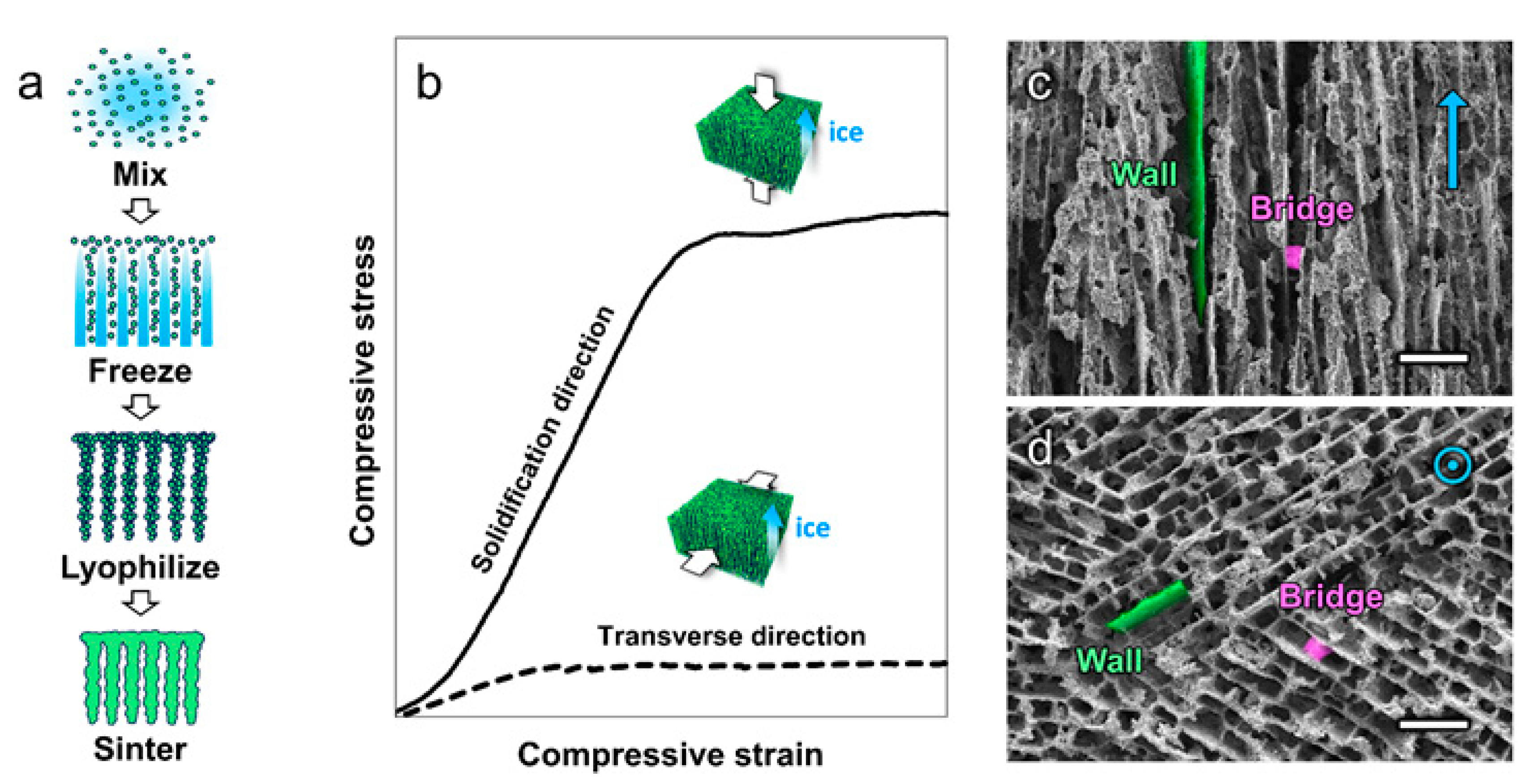
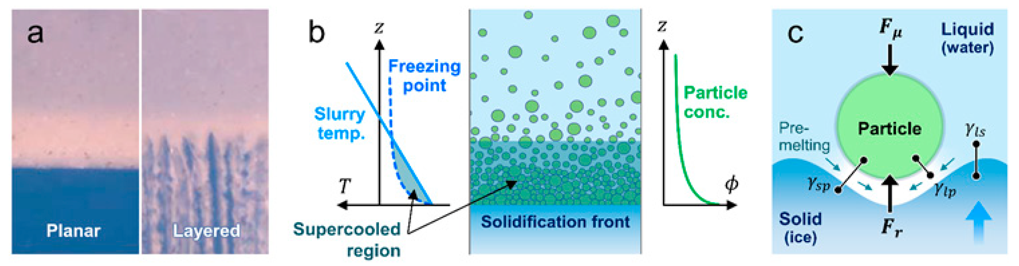
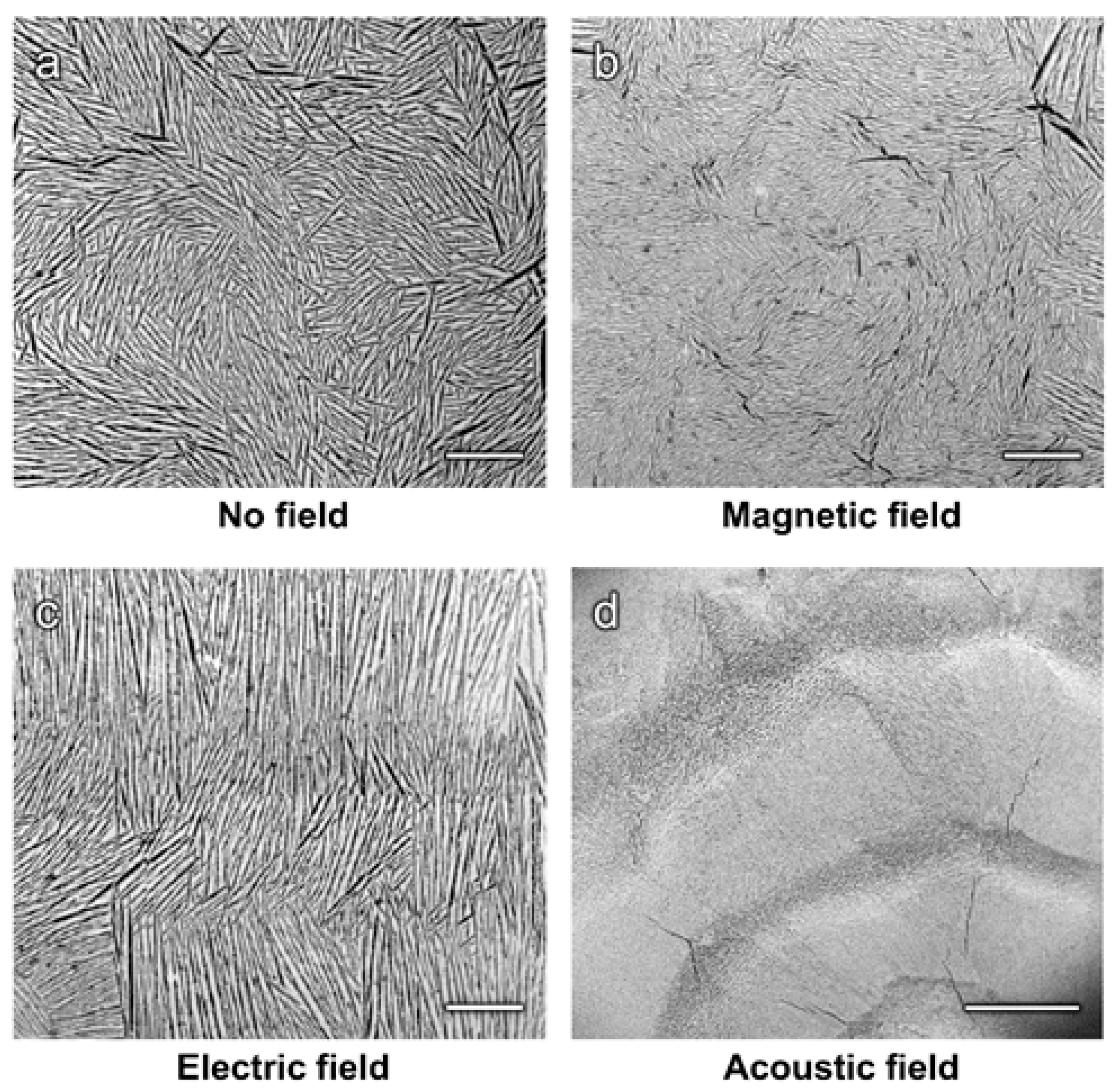
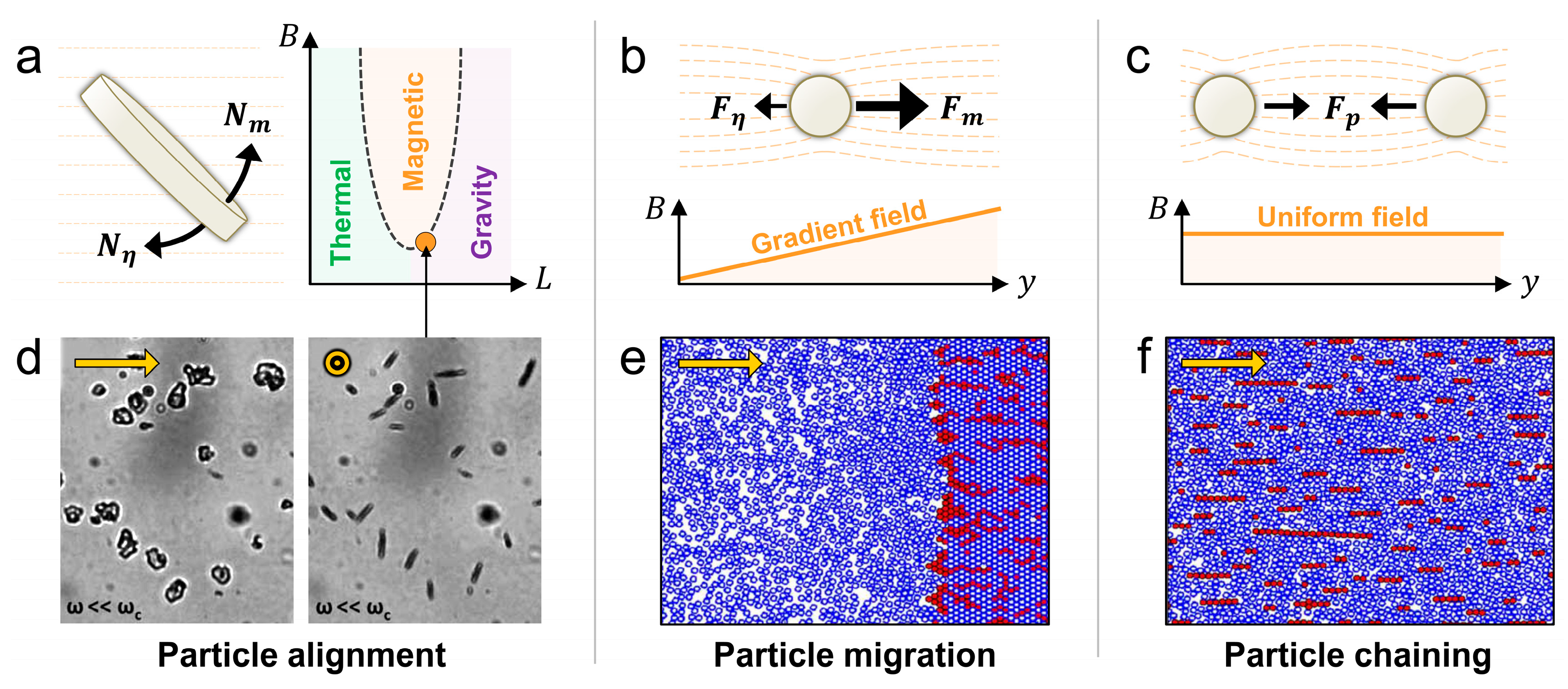
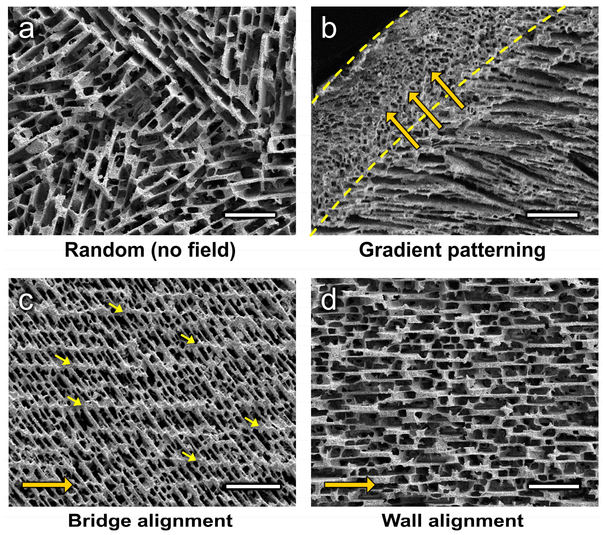
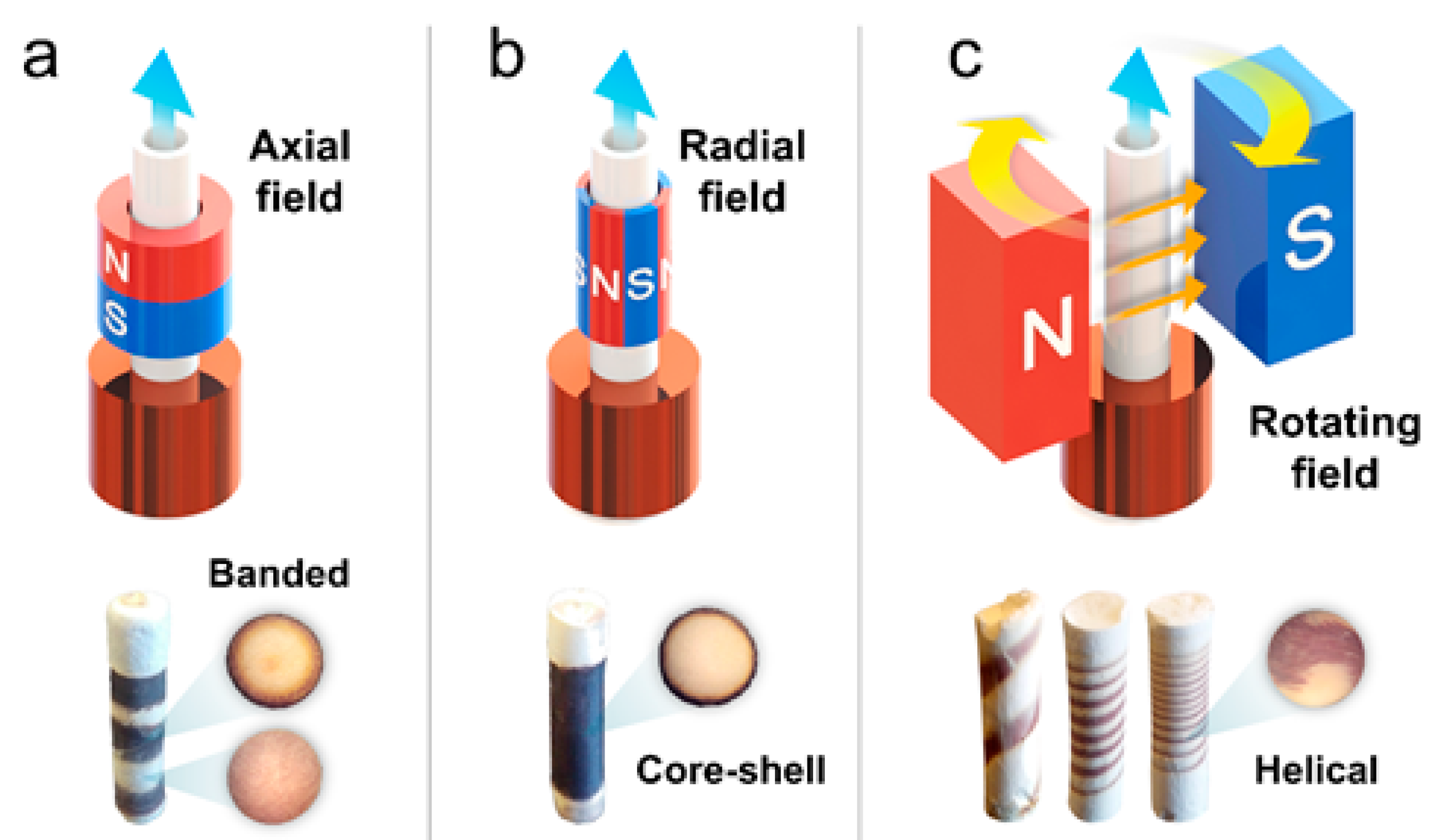
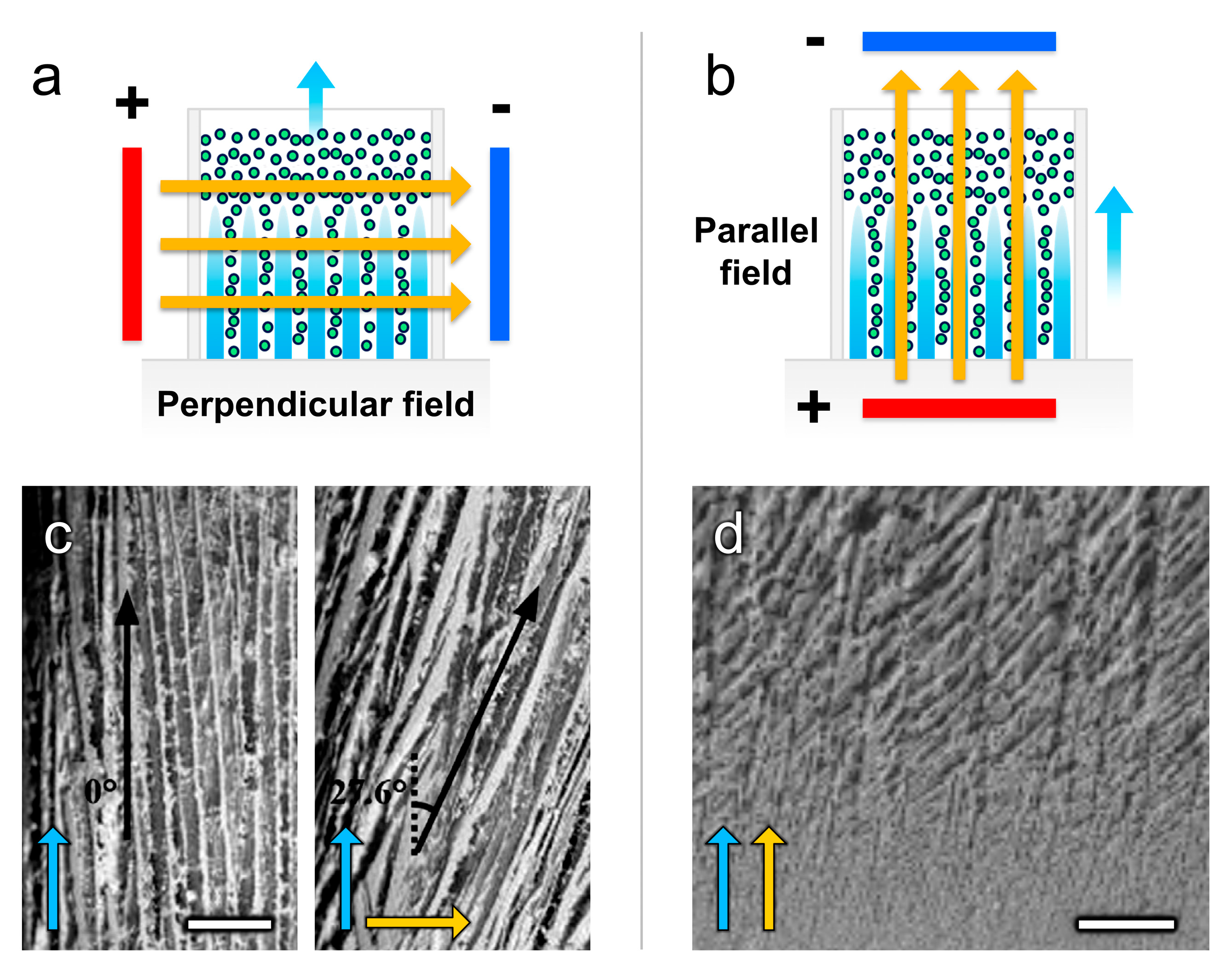
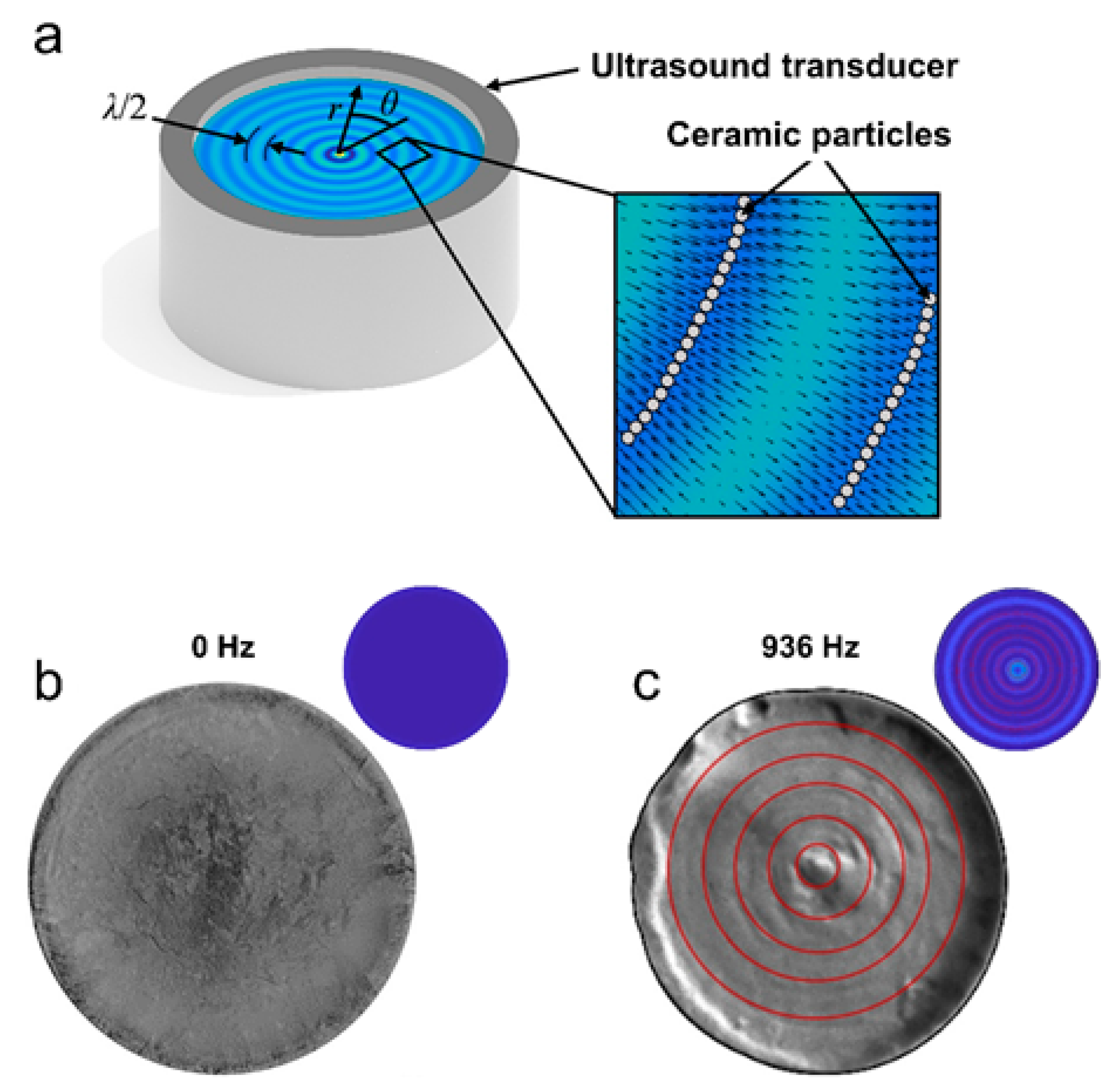
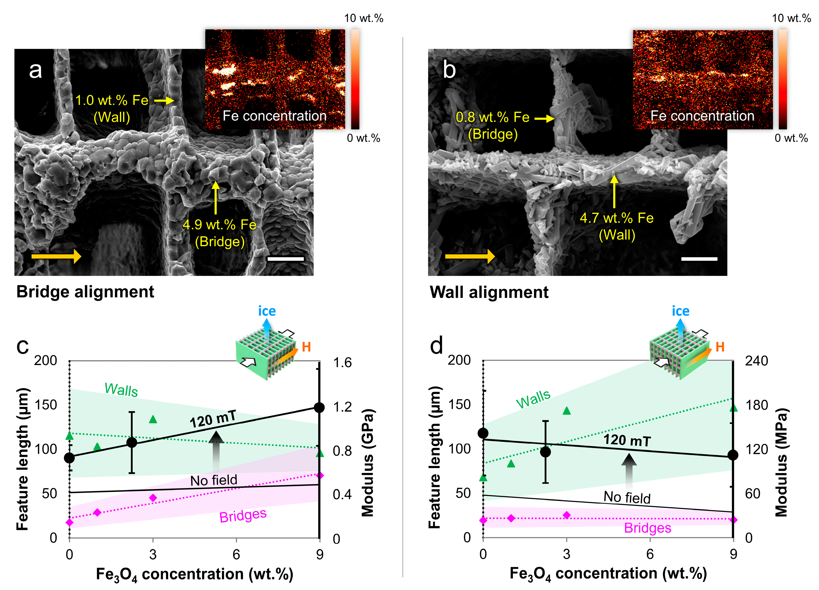
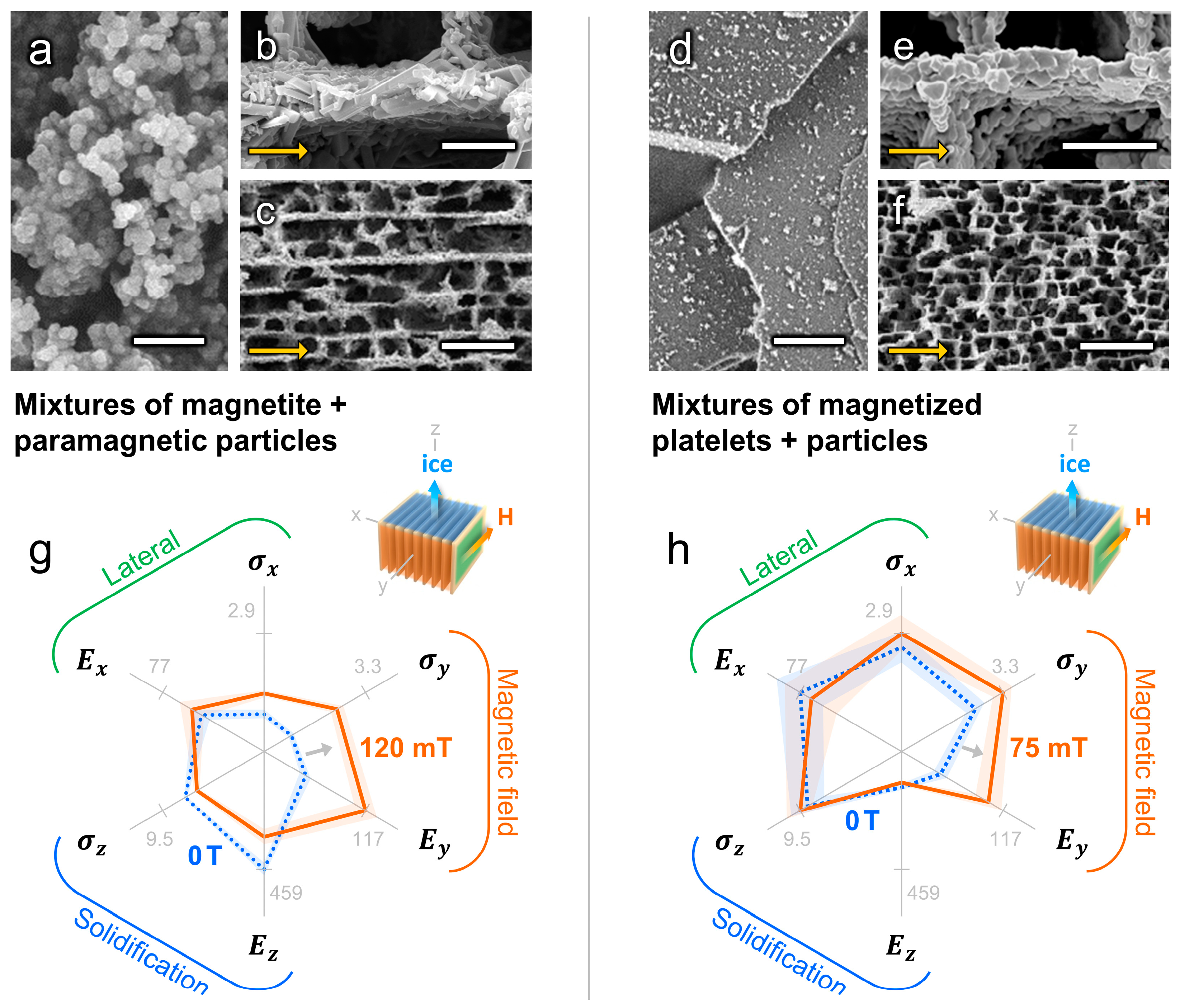
Table 1.
Overview of publications to date on external field assisted freeze casting, organized by field type: magnetic, electric, or acoustic.
Table 1.
Overview of publications to date on external field assisted freeze casting, organized by field type: magnetic, electric, or acoustic.
| Magnetic Freeze Casting | ||||||||
| Study | Particles | Particle Size | Susceptibility (or Magnetization) | Solvent | Additives | Freezing Rate, Direction | Field Strength, Orientation | Results Summary |
| [76] | HA ZrO2 Al2O3 TiO2 (+Fe3O4) | 1–3 µm 0.2–0.5 µm 2–5 µm 0.2–0.5 µm (<0.05 µm) | −81.5 × 10⁻⁶ cm3/mol −13.8 × 10⁻⁶ cm3/mol −37.0 × 10⁻⁶ cm3/mol +5.9 × 10⁻⁶ cm3/mol | Water | PEG, PVA, Darvan 811 | 10 °C/min, longitudinal | 0–0.12 T, transverse and rotating | Mixtures of Fe3O4 + HA, ZrO2, or Al2O3 under static and rotating transverse fields yielded biphasic iron-rich/poor structures; mixtures of Fe3O4 + TiO2 yielded wall alignment with enhanced transverse compressive properties. |
| [77] | ZrO2 (+Fe3O4) | 0.2–0.5 µm (<0.05 µm) | −13.8 × 10⁻⁶ cm3/mol | Water | PEG, PVA, Darvan 811 | 10 °C/min, longitudinal | 0–0.12 T, rotating | Mixtures of Fe3O4 + ZrO2 under rotating transverse fields yielded helix-reinforced composites with enhanced torsional properties. |
| [64] | ZrO2 (+Fe3O4) | 0.2–0.5 µm (<0.05 µm) | −13.8 × 10⁻⁶ cm3/mol | Water | PEG, PVA, Darvan 811 | 10 °C/min, longitudinal | 0–0.5 T, axial, radial and transverse | Mixtures of Fe3O4 + ZrO2 under static axial, radial, and transverse fields yielded different gradient patterns and bridge alignment with enhanced transverse compressive properties. |
| [80] | CeO2 Y2O3 (+Fe3O4) | <0.5 µm <0.5 µm (<0.05 µm) | +26.0 × 10⁻⁶ cm3/mol +44.4 × 10⁻⁶ cm3/mol | Water | PEG, PVA, Darvan 811 | 10 °C/min, longitudinal | 0–0.15 T, transverse | Mixtures of Fe3O4 + CeO2 or Y2O3 under static near-uniform fields yielded bridge alignment; under static gradient fields yielded biphasic iron-rich/poor structures. |
| [79] | Surface-magnetized Al2O3 | 0.35 µm (particles) 0.20 × 5 µm (platelets) | 2 × 10⁻¹⁴ emu (magnetization) 454 × 10−14 emu (magnetization) | Water | PEG, PVA, Darvan 811 | 10 °C/min, longitudinal | 0–0.075 T transverse | Mixtures of Al2O3 particles + platelets under static transverse fields yielded wall alignment with enhanced transverse compressive properties. |
| [78] | Surface-magnetized Al2O3 | 0.15–0.5 µm | 0.6–2 × 10⁻¹⁴ emu (magnetization) | Water | PEG, PVA, Darvan 811 | 10 °C/min, longitudinal | 0–0.15 T transverse | Uniform dispersions of Al2O3 particles under static transverse fields yielded wall alignment with enhanced compressive properties. |
| [74] | Surface-magnetized Fe3O4 | 0.25 µm | 11–16 emu/g (magnetization) | Water | PEG, PVA, Darvan 811 | 10 °C/min, longitudinal | 0–0.005 T longitudinal | Uniform dispersions of Fe3O4 particles under uniform longitudinal fields formed by Helmholtz coils yielded wall alignment and decreased porosity with enhanced compressive properties. |
| [86] | Al2O3 | 1 µm | −37.0 × 10⁻⁶ cm3/mol | Water | CMC, PAAS | −30 °C (constant), longitudinal and transverse | 0–1.28 T transverse | Uniform dispersions of Al2O3 under static fields yielded decreased pore sizes with no effect on alignment. |
| Electric Freeze Casting | ||||||||
| Study | Particles | Particle Size | --- | Solvent | Additives | Freezing Rate, Direction | Field Strength, Orientation | Results Summary |
| [73] | Al2O3 | 0.4 µm | --- | Water | Glycerol, Darvan 7-N | 6 °C/min, longitudinal | 0–90 V, longitudinal | Uniform dispersions of Al2O3 under longitudinal fields yielded dense/porous bilayered scaffolds. |
| [81] | Al2O3 | 1 µm | --- | Water | PVA, SND 6800 | 1 °C/min, longitudinal | 0–100 kV/m, transverse | Uniform dispersions of Al2O3 under transverse fields yielded inclined lamellar walls and increased pore spacing. |
| [86] | Al2O3 | 1 µm | --- | Water | CMC, PAAS | −30 °C (constant), longitudinal and transverse | 0–150 kV/m, transverse | Uniform dispersions of Al2O3 under transverse fields yielded aligned walls and increased pore sizes with enhanced compressive properties. |
| [72] | HA | --- | --- | Water + H2O2 | SND 6800 | −20 °C (constant), longitudinal | 0–90 kV/m, longitudinal | Uniform dispersions of HA in H2O2 under longitudinal fields yielded increased lamellar and spherical pore sizes. |
| Acoustic Freeze Casting | ||||||||
| Study | Particles | Particle Size | --- | Solvent | Additives | Freezing Rate, Direction | Field Frequency, Orientation | Results Summary |
| [82] | TiO2 | <0.5 µm | --- | Water | PEG, PVA, Darvan 811 | 10 °C/min, longitudinal | 0–936 kHz, radial | Uniform dispersions of TiO2 under acoustic wave fields yielded concentric ring-like structures with gradient hardness distributions. |
© 2019 by the authors. Licensee MDPI, Basel, Switzerland. This article is an open access article distributed under the terms and conditions of the Creative Commons Attribution (CC BY) license (http://creativecommons.org/licenses/by/4.0/).
Share and Cite
MDPI and ACS Style
Niksiar, P.; Su, F.Y.; Frank, M.B.; Ogden, T.A.; Naleway, S.E.; Meyers, M.A.; McKittrick, J.; Porter, M.M. External Field Assisted Freeze Casting. Ceramics 2019, 2, 208-234. https://0-doi-org.brum.beds.ac.uk/10.3390/ceramics2010018
AMA Style
Niksiar P, Su FY, Frank MB, Ogden TA, Naleway SE, Meyers MA, McKittrick J, Porter MM. External Field Assisted Freeze Casting. Ceramics. 2019; 2(1):208-234. https://0-doi-org.brum.beds.ac.uk/10.3390/ceramics2010018
Chicago/Turabian StyleNiksiar, Pooya, Frances Y. Su, Michael B. Frank, Taylor A. Ogden, Steven E. Naleway, Marc A. Meyers, Joanna McKittrick, and Michael M. Porter. 2019. "External Field Assisted Freeze Casting" Ceramics 2, no. 1: 208-234. https://0-doi-org.brum.beds.ac.uk/10.3390/ceramics2010018