Article

The Influence of Kinematic Conditions and Variations in Component Positioning on the Severity of Edge Loading and Wear of Ceramic-on-Ceramic Hip Bearings

1
Institute of Medical and Biological Engineering, School of Mechanical Engineering, University of Leeds, Leeds LS2 9JT, UK
2
DePuySynthes Joint Reconstruction, Leeds LS11 8DT, UK
*
Author to whom correspondence should be addressed.
Submission received: 24 May 2019 / Revised: 5 July 2019 / Accepted: 16 July 2019 / Published: 1 August 2019
(This article belongs to the Special Issue Ceramics for Biomedical Applications)

Abstract

:
Dynamic separation and direct edge loading of hip replacement bearings can be caused by many factors, including implant positioning, implant design, changes in device over time, surgical variations and patient variations. Such dynamic separation and direct edge loading can lead to increased wear. Different input kinematic conditions have been used for experimental hip simulator studies to produce clinically relevant elliptical contact wear paths between the bearings during gait. The aim of this study was to investigate the influence of input kinematics (two axes of rotation simulation conditions (without abduction/adduction) and three axes of rotation simulation conditions (with abduction/adduction and different loading profiles) and variations in component positioning (different levels of medial-lateral translational mismatch at standard and steep cup inclination angles) on the occurrence, severity of edge loading, dynamic separation and wear of size 36 mm ceramic-on-ceramic hip bearings on an electromechanical hip joint simulator. The results showed that, overall, either of the two axes or three axes input profiles were equally valid in providing a suitable preclinical testing method for assessing the occurrence and severity of edge loading and wear under edge loading conditions. In terms of component positioning, as cup inclination and medial-lateral translational mismatch increased, so did dynamic separation, axial load at the rim, severity of edge loading and wear.

1. Introduction

Low wear rates of ceramic-on-ceramic hip replacements have been reported under standard gait conditions from hip simulator studies, despite variations in wear rates and the presence of stripe wear patterns being observed in clinical retrievals [1,2,3]. Such stripe wear patterns are understood to be caused by high contact stresses occurring between the femoral head and the rim of the acetabular cup as a result of direct edge loading [1,4,5,6,7]. It has been shown that for ceramic-on-ceramic bearings, steep cup inclination angle alone did not result in stripe wear in in vitro simulator studies [8]. It was only when Nevelos et al. introduced microseparation and edge loading to the simulation cycle that the stripe wear pattern, elevated wear rates and a bimodal particle distribution were produced, hence replicating clinical wear rates, wear patterns and wear particles [9,10,11].
Clinically, separation of the head from the cup has been observed using fluoroscopy during different patient activities including the walking gait cycle [12]. Dynamic separation can be defined as the distance between the femoral head and actebular cup bearing centres during gait. It is important to note that there is actually no loss of contact between the femoral head and the acteabular cup. Dynamic separation and direct edge loading (as opposed to non-direct edge loading, i.e., following impingement) can be caused by many factors, including implant positioning, implant design, changes in device over time, surgical variations and patient variations [8,10,13,14,15,16,17,18,19]. Variation in implant positioning includes rotational positioning around three anatomical axes, and translational positioning along three anatomical axes. Specifically, rotational positioning of the acetabular cup can be described as cup inclination (rotation about the anterior-posterior (A-P) axis), version (rotation about the superior-inferior (S-I) axis) and tilt (rotation about the medial-lateral (M-L) axis). The translational position of the femoral head and the acetabular cup can be defined as the position of the centres of the rotations of the acetabular cup and femoral head relative to each other along the medial-lateral, anterior-posterior and/or superior-inferior axes. It is the mismatch between the femoral head and acetabular cup centres in the simulator that is required to replicate the dynamic separation observed in vivo [10]. Original hip simulation studies from Leeds fixed the level of dynamic separation along the medial-lateral axis as the input to produce stripe wear, which in effect predetermined the level of severity. This original methodology was termed ‘microseparation’. More recently, varying levels of medial-lateral translational positioning mismatch have been used as inputs, resulting in different levels of dynamic separation (which can be greater than the originally defined level of 0.5 mm microseparation), and hence the occurrence and severity of edge loading [20]. In this new approach, the level of separation (severity of edge loading) is an output of the system. This approach means that the influence of factors such as design, head diameter, coverage angle, etc., on the level of dynamic separation and severity of edge loading, and hence wear, can be studied. This two stage approach of determining the biomechanical outputs of dynamic separation and severity of edge loading (stage one) and wear (stage two) has been recently described by O’Dwyer Lancaster–Jones et al. [20]. It allows a large number of biomechanical conditions to be evaluated, informing the conditions of subsequent wear studies.
The design and complexity of hip joint simulators and the selection of input parameters has varied [21,22]. Hip joint motions and loads have been typically applied using electromechanical, hydraulic or pneumatic systems. Both two axes (flexion/extension and internal/external rotation) and three axes (flexion/extension, internal/external rotation and abduction/adduction) of rotation conditions have been used for experimental hip simulator studies to produce clinically relevant elliptical contact wear paths between the bearings during gait [23,24]. The international standard ISO 14242-1 [25] describes three axes of rotation conditions to simulate the full range of physiological motion based on the standard walking cycle. In the past, it has not been uncommon for simulation of the standard walking cycle for two axes of rotation profiles to have been used with increased magnitudes of flexion/extension angular displacements and phasing to replicate the equivalent of three axis of rotation and to compensate for the lack of abduction/adduction motion [24]. The effects of these two different simulation approaches are now investigated in combination with the recent advances in the approach to simulation of dynamic separation and edge loading.
The aim of this study was to:
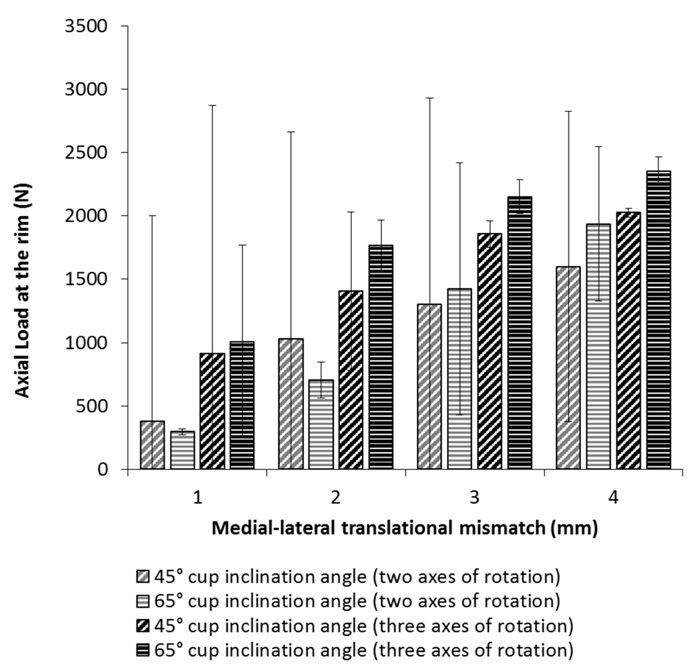
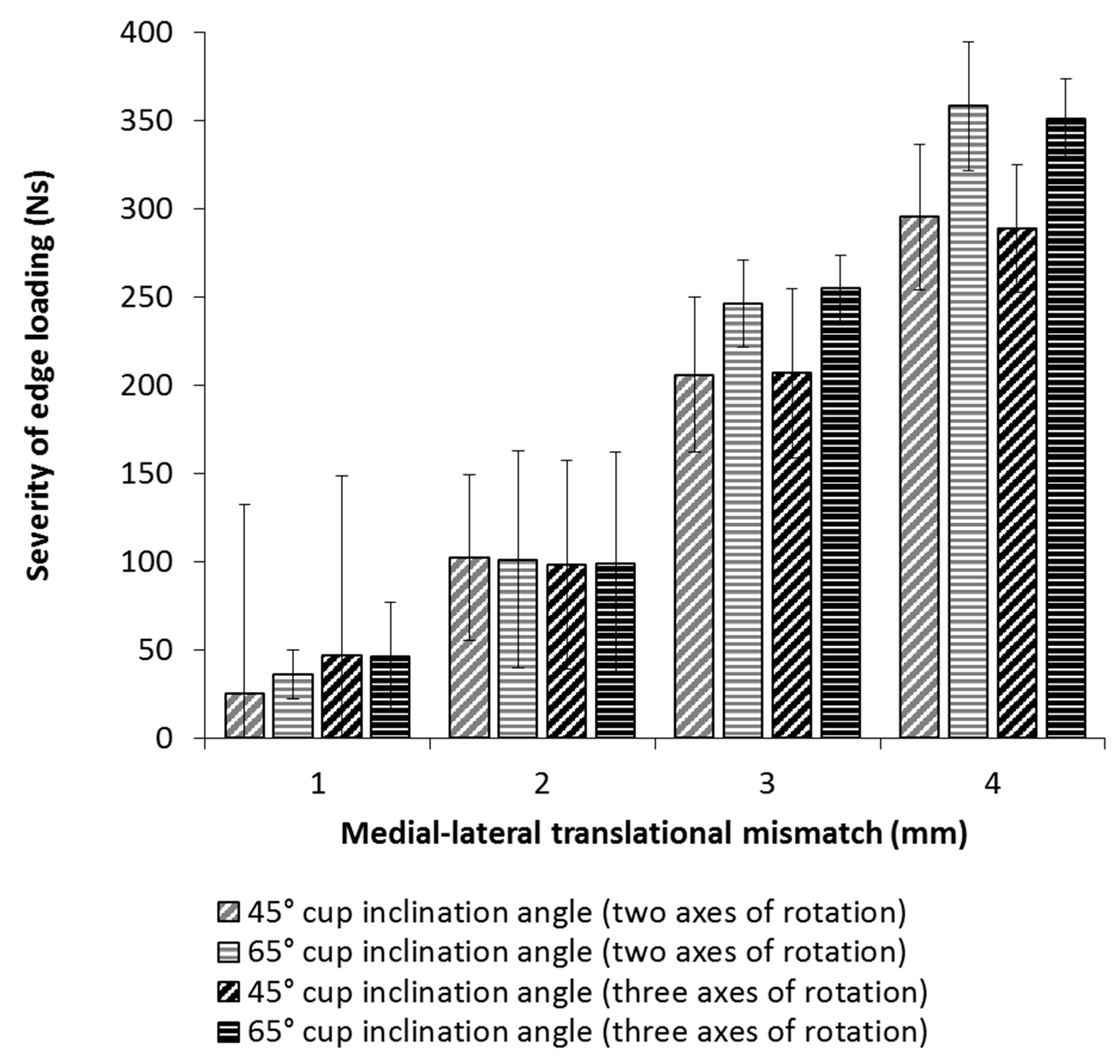
  • Investigate the occurrence and severity of edge loading and dynamic separation under different levels of medial-lateral translational mismatch at standard and steep cup inclination angles (biomechanical study), under two axes of rotation simulation conditions (without abduction/adduction) and three axes of rotation simulation conditions (with abduction/adduction) with different loading profiles.
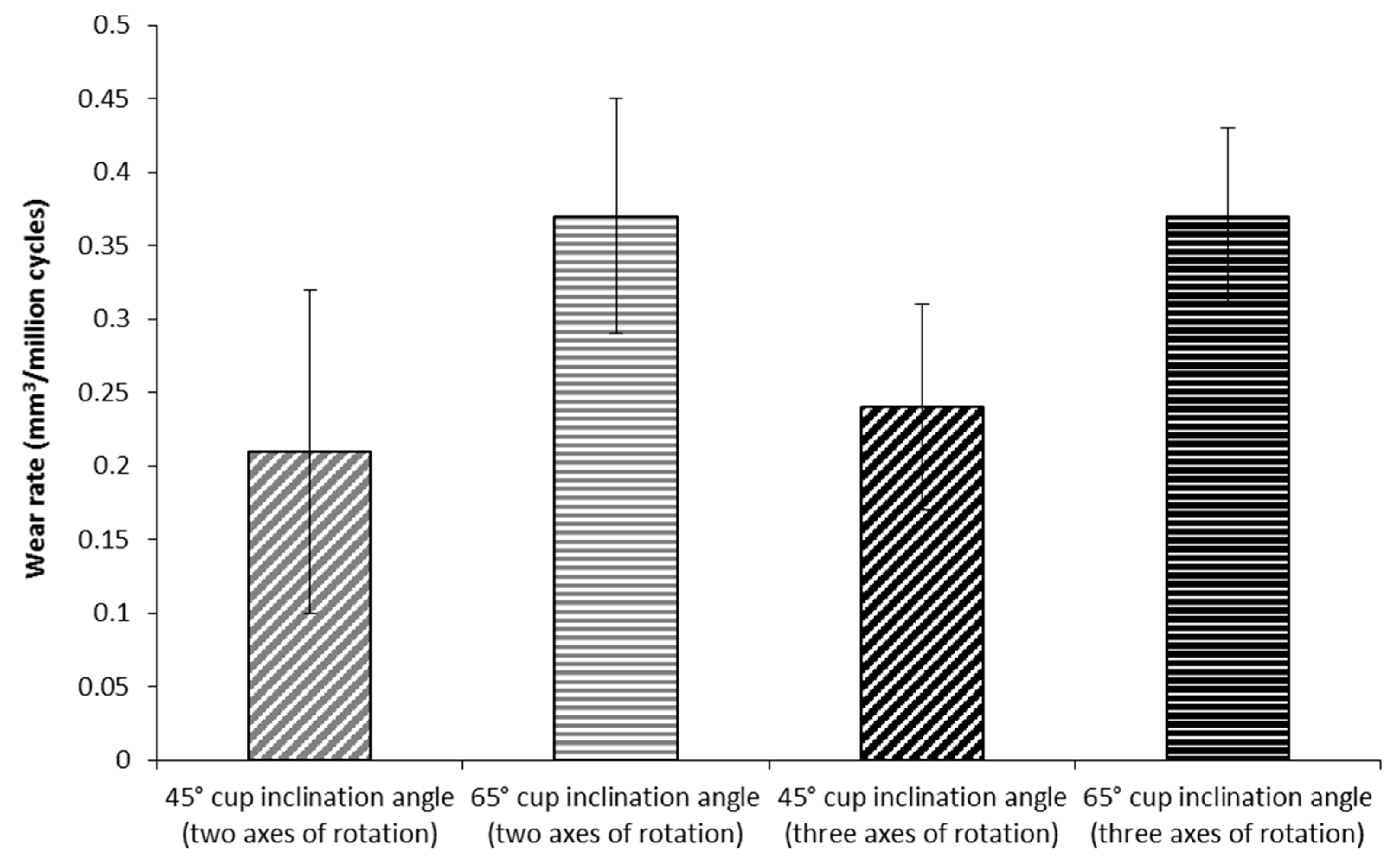
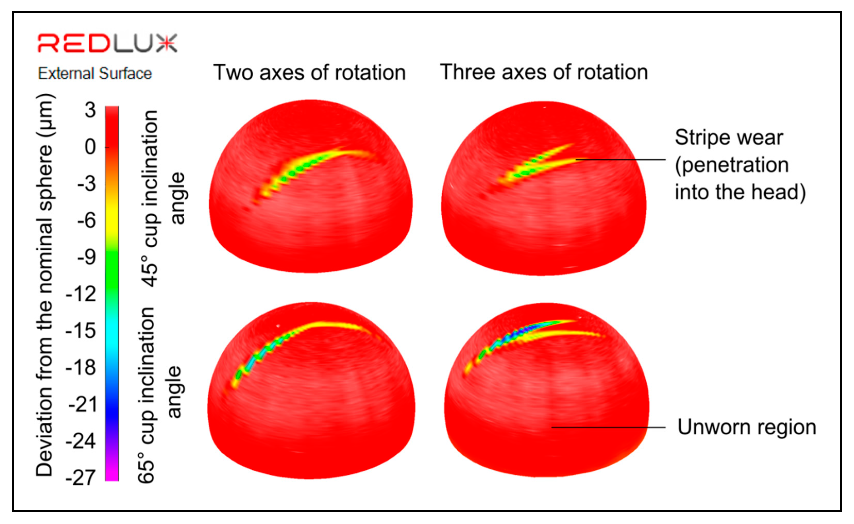
  • Determine the wear of ceramic-on-ceramic bearings under edge loading conditions at standard and steep cup inclination angles (wear study), under two axes of rotation simulation conditions (without abduction/adduction) and three axes of rotation simulation conditions (with abduction/adduction and different loading profiles).

2. Materials and Methods

Ceramic-on-ceramic (BIOLOX®delta) 36 mm diameter hip replacement bearings (PINNACLE®, DePuy Synthes Joint Reconstruction, Leeds, UK), with a nominal diametric clearance of 100 micrometres, were investigated using an electromechanical hip joint simulator (ProSim EM13, Simulation Solutions, Stockport, UK) [26] (Figure 1). The femoral head was placed onto a vertical spigot with a 12/14 taper and the acetabular cup was press fit into a metallic shell (PINNACLE®, DePuy Synthes Joint Reconstruction, Leeds, UK). In the ProSim EM13, the angular rotations (flexion/extension, adduction/abduction and internal/external rotation) were all applied to the femoral head, and the axial loading was through the cup.
This study was in two parts. Part one consisted of biomechanical studies to investigate the magnitude of dynamic separation, maximum load at the rim at 0.1 mm of dynamic separation and the severity of edge loading under different levels of translational mismatch conditions at cup inclination angles equivalent to 45° and 65° in vivo [27,28]. The 45° cup inclination angle is currently considered a target inclination angle during surgery, whereas the 65° angle is considered a steep cup inclination angle. Following the biomechanical investigations, part two of the study involved determining the wear and stripe wear pattern of ceramic-on-ceramic bearings with a medial-lateral translational mismatch of 4 mm at 45° and 65° cup inclination angles.
Six ceramic-on-ceramic bearings were used for the biomechanical study (part 1). Three axes (Figure 2a) and two axes (Figure 2b) of rotation conditions [24,25] with 0, 1, 2, 3 and 4 mm of translational mismatch were applied between the head and cup bearing centres for cups inclined at 45° (n = 3) and 65° (n = 3). Zero mismatch represented standard concentric conditions, which included an offset due to the radial clearance between the femoral head and acetabular cup under axial loading conditions (Figure 3a). The two axes of rotation input conditions consisted of internal/external rotation out of phase with the flexion/extension profile and increased range of motion to compensate for the lack of abduction/adduction motion. The three axes of rotation input condition used the conditions described in the international standard ISO 14242-1 [25], which included abduction/adduction motion.
Twenty-four 36 mm diameter ceramic-on-ceramic bearings were used for the wear studies (part 2). Two axes of rotation conditions at 45° (n = 6) and 65° (n = 6) cup inclination angles with 4 mm translational mismatch was applied for three million cycles. Three axes of rotation conditions at 45° (n = 6) and 65° (n = 6) cup inclination angles with 4 mm translational mismatch was applied for three million cycles.
The medial-lateral translational mismatch was set by offsetting the cup medially from the femoral head to obtain the required level of mismatch (Figure 3b). The medial-lateral spring was set to its free length at the required level of translation mismatch (0, 1, 2, 3 or 4 mm). The centre of rotation was fixed for the femoral head and the cup was allowed to translate along the medial-lateral (and anterior-posterior) axis. A spring with a spring constant of 100 N/mm was used to apply a medial-lateral load, consistent with previous studies [10,20]. The head and cup were concentric when the spring was fully compressed (Figure 3c). The separation between the head and cup (Figure 3d) occurred before, during and after the swing phase, when the axial load was low enough to allow the head and cup to separate. Linear Variable Displacement Sensors (LVDTs) were used to set the translational mismatch between the bearing centres and to measure the medial-lateral dynamic separation during the gait cycle. A six axis load cell above each cup (Figure 1) measured the output axial force and medial-lateral force.
The lubricant used throughout was 25% new-born calf serum supplemented with 0.03% sodium azide to minimise bacterial growth. For the wear simulation studies, the serum was changed approximately every 330,000 cycles.
For the biomechanical studies, the simulator was run for 500 cycles at 1Hz, with 128 data points recorded during each cycle. The severity of edge loading was determined by calculating the area under the axial force and medial-lateral force curves during edge loading due to dynamic separation, as discussed in a previous study [20]. The load at the rim during edge loading conditions was determined when the relative medial-lateral displacement between the head and cup centre of rotation was 0.1 mm.
Gravimetric and geometric measurements were carried out at one million cycle intervals. At each measurement interval, the components were removed from the simulators and cleaned in accordance with a standard operating procedure. The gravimetric wear was determined using a microbalance (Mettler Toledo XP205 analytical balance, Greifensee, Switzerland), which had a readability of 0.01 mg. The change in mass was converted to volumetric wear using a density of 4.37 × 10⁻³ g/mm3 for BIOLOX®delta. The geometric measurements were carried out using a coordinate measurement machine (Legex 322, Mitutoyo, Japan). Redlux software (Southampton, UK) was used to construct a three-dimensional map of the acetabular cup and femoral head surfaces. Mean values and 95% confidence limits were determined, and two way ANOVA was used for statistical analysis of the wear rates (two variables of inclination angle and number of rotation axes) with significance levels taken at p < 0.05.
The data associated with this article is openly available from the University of Leeds data repository [29].

3. Results

The medial-lateral dynamic separation between the head and cup centres of rotations under two axes and three axes of rotations with 1, 2, 3 and 4 mm of translational mismatches at 45° and 65° cup inclination angles is shown in Figure 4. No dynamic separation was observed with zero mismatch. Similar values of dynamic separation were observed under two axes and three axes of rotation conditions. The magnitude of dynamic separation increased as the level of medial-lateral translational mismatch increased from 1 mm through to 4 mm. The largest magnitude of dynamic separation during gait occurred with 4 mm of translational mismatch at a 65° cup inclination angle. Under two axes of rotation conditions the dynamic separation was greater at a 65° cup inclination angle compared to 45° at 1, 2, 3 and 4 mm of translational mismatch conditions. This was the same for the three axes of rotation conditions, with the exception of 1 mm of translational mismatch, where a similar dynamic separation was observed under both cup inclination angles (Figure 4).
The load at the rim, measured when the separation between the head and cup reached 0.1 mm following heel strike under two axes and three axes of rotation conditions with 1, 2, 3 and 4 mm of translational mismatch at 45° and 65° cup inclination angles, is shown in Figure 5. Larger mean rim loads were observed for ceramic-on-ceramic bearings under three axes compared with two axes of rotation conditions. The rim load increased as the levels of translational mismatch increased under both two axes and three axes of rotation conditions. The highest mean value measured was at 4 mm of mismatch with a 65° cup inclination angle condition. The lowest rim loads occurred at 1 mm of translational mismatch at 45° and 65° cup inclination angles. No rim loads due to dynamic separation were observed with zero translational mismatch conditions.
The severity of edge loading under two axes and three axes of rotation conditions with 1, 2, 3 and 4 mm of translational mismatch at 45° and 65° cup inclination angles is shown in Figure 6. There was an increase in the severity of edge loading due to dynamic separation as the translational mismatch between the head and cup increased. The largest severity of edge loading occurred at 4 mm of translational mismatch conditions at a 65° cup inclination angle. The severity of edge loading was similar under two axes and three axes of rotation conditions.
Following on from the biomechanical investigation, the wear rates of ceramic-on-ceramic bearings were determined under edge loading conditions with 4 mm medial-lateral translational mismatch for both 45° and 65° cup inclination angles (Figure 7). There was no significant difference between the mean wear rates under two axes and three axes of rotation conditions (p = 0.50, two way ANOVA). There was a significant increase in the wear rate at a 65° cup inclination angle compared with a 45° cup inclination angle (p < 0.01, two way ANOVA).
Stripe wear patterns were observed on the femoral heads under edge loading conditions (Figure 8). The maximum wear penetration depths on the heads were observed within the wear stripe region. The wear stripe patterns generated under the two axes of rotation condition were different to those generated under the three axes of rotation condition, with more of a ‘two pronged’ stripe shape being observed under the three axes of rotation condition. A steeper cup inclination angle of 65° resulted in a stripe wear pattern on the femoral head that was located more superiorly compared to the stripe wear pattern with a 45° cup inclination angle.

4. Discussion

The aim of this study was to investigate the influence of input kinematics and variations in component positioning on the severity of edge loading and wear of ceramic-on-ceramic hip bearings on an electromechanical hip joint simulator.
Both the three axes and two axes of rotation input conditions (Figure 2) resulted in similar maximum dynamic separation during gait at 2, 3 and 4 mm of medial-lateral translational mismatch. Applying three axes of rotation resulted in higher rim loads during edge loading at 0.1 mm of separation compared with the rim loads when the two axes of rotation conditions was applied. It is anticipated that the differences in loading rate and profile between the two conditions (Figure 2) contributed to the different rim loads at 0.1 mm of separation. The load at the rim measurement showed an increase at higher levels of medial-lateral translational mismatch, however, for a wider assessment of edge loading, the severity of edge loading throughout the cycle was also considered. When measuring the severity of edge loading across the complete gait cycle, similar results were observed when two axes and three axes of rotation conditions were applied. There were no significant differences in wear rates between the two input conditions. However, there was a difference in the stripe wear pattern on the femoral head (Figure 8), which appeared to have more of a ‘two pronged’ stripe shape under the three axes of rotation condition. The similar dynamic separation, severity of edge loading and wear, yet difference in axial load at the rim, indicates that the output of axial load at the rim may have limited usefulness.
These results show that, overall, either of the two axes or three axes input profiles shown in Figure 2 were equally valid in providing a suitable preclinical testing method for assessing the occurrence and severity of edge loading and wear under edge loading conditions. However, the increased complexity of simulation in three axes, although more closely replicating physiological joint biomechanics and in vivo conditions, does need to be considered.
This study has shown higher levels of dynamic separation, axial load at the rim, severity of edge loading and wear as cup inclination and medial-lateral translational mismatch increases, consistent with a previous study [20]. The larger rim loads and severity of edge loading at higher levels of mismatch correlates to the increased wear rates, showing the advantages of the recently described two phase approach used to study the mechanics of hip replacements under a range of conditions. Through the use of a biomechanical stage, the occurrence and severity of edge loading can be investigated before wear simulation is carried out to assess the tribological performance of hip replacement bearings. A similar wear rate at a 45° cup inclination angle with 4 mm of translational mismatch was reported in a previous study for ceramic-on-ceramic bearings of the same size and type (0.3 mm3/million cycles, compared to 0.21 mm3/million cycles in this study under two axes of rotation conditions) [20]. However, higher wear and severity of edge loading was reported at a 65° cup inclination angle with 4 mm of translational mismatch in the same previous study (1 mm3/million cycles, compared to 0.37 mm3/million cycles in this study under two axes of rotation conditions) [20]. Differences in simulator design and mechanics could have contributed to the difference in the severity of edge loading and wear rates between the two studies. The previous study was performed using the Leeds II Physiological Anatomical Hip Simulator, which is a hydraulic simulator that has two axes of rotation conditions and used the same input profiles as the two axes of rotation conditions described in this study (Figure 2b). This does nonetheless demonstrate how the approach to setting the medial-lateral translational mismatch can be replicated across different designs of hip simulators. Further, the approach can clearly differentiate the wear performance of ceramic-on-ceramic bearings. It is important to note that in new product development and regulatory testing, simulations would be used in a comparative approach to an existing predicate device with clinical history, and results of different devices should not be compared across different simulation methods.
Although the wear rates of ceramic-on-ceramic bearings observed in this study and previous studies are low (<1 mm3/million cycles), there is a demand for hip replacements to function under a wide range of conditions in younger and more active patients for longer term durations. Further, since most current composite ceramic-on-ceramic bearings are zirconia-based, hydrothermal ageing of zirconia can be a concern in the longer term [30,31]. Therefore, future studies should consider a wider range of parameters, including the influence of ageing, as well as variations in version angle and variations in anterior-posterior translational positioning (anterior-posterior offset deficiency). These latter two factors are understood to vary clinically, and these may also impact on the long term success of hip replacements in the future.

5. Conclusions

The input kinematic conditions in terms of two axes of rotation simulation conditions (without abduction/adduction) and three axes of rotation simulation conditions (with abduction/adduction and different loading profiles) did not influence the occurrence, severity of edge loading, dynamic separation or wear of 36 mm ceramic-on-ceramic bearings under different levels of medial-lateral translational mismatch at standard and steep cup inclination angles. However, the occurrence, severity of edge loading, dynamic separation and wear of 36 mm ceramic-on-ceramic bearings was influenced by variations in component positioning, with a significantly higher wear rate for a 65° cup inclination angle compared to a 45° cup inclination angle (with 4 mm medial-lateral translational mismatch).

Author Contributions

Conceptualization, J.F. and L.M.J.; methodology, J.F., M.A.-H. and L.M.J.; validation, J.F., L.M.J. and M.A.-H.; formal analysis, M.A. and L.M.J.; investigation, M.A. and M.A.-H.; resources, J.F. and L.M.J.; data curation, M.A. and L.M.J.; writing—original draft preparation, M.A, M.A.-H. and L.M.J.; writing—review and editing, L.M.J.; visualization, M.A., M.A.-H. and L.M.J.; supervision, J.F. and L.M.J.; project administration, L.M.J.; funding acquisition, J.F. and L.M.J.

Funding

This research was funded by the Innovation and Knowledge Centre in Medical Technologies funded by the EPSRC, TSB and BBSRC, grant number EP/J017620/1, and by the EPSRC Centre for Innovative Manufacturing in Medical Devices, grant number EP/K029592/1.

Acknowledgments

J Fisher is an NIHR Senior Investigator and his research is supported through the NIHR Leeds Musculoskeletal Biomedical Research Unit. DePuy Synthes supplied the components.

Conflicts of Interest

The authors declare no conflict of interest. The funders had no role in the design of the study; in the collection, analyses, or interpretation of data; in the writing of the manuscript, or in the decision to publish the results.

References

  1. Nevelos, J.E.; Ingham, E.; Doyle, C.; Fisher, J.; Nevelos, A.B. Analysis of retrieved alumina ceramic components from Mittelmeier total hip prostheses. Biomaterials 1999, 20, 1833–1840. [Google Scholar] [CrossRef]
  2. Nevelos, J.E.; Ingham, E.C.; Doyle, C.; Nevelos, A.B.; Fisher, J. Wear of HIPed and non-HIPed alumina-alumina hip joints under standard and severe simulator testing conditions. Biomaterials 2001, 22, 2191–2197. [Google Scholar] [CrossRef]
  3. Lusty, P.J.; Tai, C.C.; Sew-Hoy, R.P.; Walter, W.L.; Walter, W.K.; Zicat, B.A. Third-generation alumina-on-alumina ceramic bearings in cementless total hip arthroplasty. J. Bone Jt. Surg. Am. 2007, 89, 2676–2683. [Google Scholar] [CrossRef] [PubMed]
  4. Nevelos, J.E.; Prudhommeaux, F.; Hamadouche, M.; Doyle, C.; Ingham, E.; Meunier, A.; Nevelos, A.B.; Sedel, L.; Fisher, J. Comparative analysis of two different types of alumina-alumina hip prosthesis retrieved for aseptic loosening. Bone Joint J. 2001, 83, 598–603. [Google Scholar] [CrossRef]
  5. Jeffers, J.R.T.; Walter, W.L. Ceramic-on-ceramic bearings in hip arthroplasty: State of the art and the future. J. Bone Jt. Surg. Br. Vol. 2012, 94, 735–745. [Google Scholar] [CrossRef] [PubMed]
  6. Mak, M.; Jin, Z.; Fisher, J.; Stewart, T.D. Influence of Acetabular Cup Rim Design on the Contact Stress During Edge Loading in Ceramic-on-Ceramic Hip Prostheses. J. Arthroplast. 2011, 26, 131–136. [Google Scholar] [CrossRef] [PubMed]
  7. Sariali, E.; Stewart, T.; Jin, Z.; Fisher, J. Effect of cup abduction angle and head lateral microseparation on contact stresses in ceramic-on-ceramic total hip arthroplasty. J. Biomech. 2012, 45, 390–393. [Google Scholar] [CrossRef]
  8. Nevelos, J.E.; Ingham, E.; Doyle, C.; Nevelos, A.B.; Fisher, J. The influence of acetabular cup angle on the wear of ‘BIOLOX Forte’ alumina ceramic bearing couples in a hip joint simulator. J. Mater. Sci. Mater. Med. 2001, 12, 141–144. [Google Scholar] [CrossRef]
  9. Hatton, A.; Nevelos, J.E.; Nevelos, A.A.; Banks, R.E.; Fisher, J.; Ingham, E. Alumina–alumina artificial hip joints. Part I: A histological analysis and characterisation of wear debris by laser capture microdissection of tissues retrieved at revision. Biomaterials 2002, 23, 3429–3440. [Google Scholar] [CrossRef]
  10. Nevelos, J.; Ingham, E.; Doyle, C.; Streicher, R.; Nevelos, A.; Walter, W.; Fisher, J. Microseparation of the centers of alumina-alumina artificial hip joints during simulator testing produces clinically relevant wear rates and patterns. J. Arthroplasty 2000, 15, 793–795. [Google Scholar] [CrossRef]
  11. Tipper, J.L.; Hatton, A.; Nevelos, J.E.; Ingham, E.; Doyle, C.; Streicher, R.; Nevelos, A.B.; Fisher, J. Alumina–alumina artificial hip joints. Part II: Characterisation of the wear debris from in vitro hip joint simulations. Biomaterials 2002, 23, 3441–3448. [Google Scholar] [CrossRef]
  12. Komistek, R.D.; Dennis, D.A.; Ochoa, J.A.; Haas, B.D.; Hammill, C. In Vivo Comparison of Hip Separation After Metal-on-Metal or Metal-on-Polyethylene Total Hip Arthroplasty. J. Bone Jt. Surg. Am. 2002, 84, 1836–1841. [Google Scholar] [CrossRef] [PubMed]
  13. Fisher, J.; Al-Hajjar, M.; Williams, S.; Jennings, L.M.; Ingham, E. In Vitro Measurement of Wear in Joint Replacements: A Stratified Approach for Enhanced Reliability ‘SAFER’ Pre-Clinical Simulation Testing. Semin. Arthroplasty 2012, 4, 286–288. [Google Scholar] [CrossRef]
  14. Jennings, L.M.; Al-Hajjar, M.; Brockett, C.L.; Williams, S.; Tipper, J.L.; Ingham, E.; Fisher, J. (iv) Enhancing the safety and reliability of joint replacement implants. Orthop. Trauma 2012, 26, 246–252. [Google Scholar] [CrossRef] [PubMed] [Green Version]
  15. Fisher, J. Bioengineering reasons for the failure of metal-on-metal hip prostheses: An engineer’s perspective. J. Bone Jt. Surg. Br. Vol. 2011, 93, 1001–1004. [Google Scholar] [CrossRef] [PubMed]
  16. Williams, S.; Jalali-Vahid, D.; Brockett, C.; Jin, Z.; Stone, M.H.; Ingham, E.; Fisher, J. Effect of swing phase load on metal-on-metal hip lubrication, friction and wear. J. Biomech. 2006, 12, 2274–2281. [Google Scholar] [CrossRef] [PubMed]
  17. Brockett, C.; Williams, S.; Jin, Z.; Isaac, G.; Fisher, J. Friction of total hip replacements with different bearings and loading conditions. J. Biomed. Mater. Res. Part B Appl. Biomater. 2007, 81, 508–515. [Google Scholar] [CrossRef] [PubMed]
  18. Fisher, J.; Bell, J.; Barbour, P.S.M.; Tipper, J.L.; Matthews, J.B.; Besong, A.A.; Stone, M.H.; Ingham, E. A novel method for the prediction of functional biological activity of polyethylene wear debris. Proc. Inst. Mech. Eng. Part H J. Eng. Med. 2001, 215, 127–132. [Google Scholar] [CrossRef]
  19. Barbour, P.S.M.; Stone, M.H.; Fisher, J. A hip joint simulator study using new and physiologically scratched femoral heads with ultra-high molecular weight polyethylene acetabular cups. Proc. Inst. Mech. Eng. Part H J. Eng. Med. 2000, 214, 569–576. [Google Scholar] [CrossRef]
  20. Lancaster-Jones, O.O.; Williams, S.; Jennings, L.M.; Thompson, J.; Isaac, G.H.; Fisher, J.; Al-Hajjar, M. An in vitro simulation model to assess the severity of edge loading and wear, due to variations in component positioning in hip joint replacements. J. Biomed. Mater. Res. Part B 2018, 106, 1897–1906. [Google Scholar] [CrossRef]
  21. Affatato, S.; Leardini, W.; Zavalloni, M. Hip Joint Simulators: State of the Art. In Bioceramics and Alternative Bearings in Joint Arthroplasty; Benazzo, F., Falez, F., Dietrich, M., Eds.; Steinkopff: Heidelberg, Germany, 2006; pp. 171–180. [Google Scholar]
  22. Affatato, S.; Spinelli, M.; Zavalloni, M.; Mazzega-Fabbro, C.; Viceconti, M. Tribology and total hip joint replacement: Current concepts in mechanical simulation. Med. Eng. Phys. 2008, 30, 1305–1317. [Google Scholar] [CrossRef] [PubMed]
  23. Calonius, O.; Saikko, V. Slide track analysis of eight contemporary hip simulator designs. J. Biomech. 2002, 35, 1439–1450. [Google Scholar] [CrossRef]
  24. Barbour, P.S.M.; Stone, M.H.; Fisher, J. A hip joint simulator study using simplified loading and motion cycles generating physiological wear paths and rates. Proc. Inst. Mech. Eng. Part H J. Eng. Med. 1999, 213, 455–467. [Google Scholar] [CrossRef] [PubMed]
  25. ISO 14242-1:2014. Implants for Surgery—Wear of Total Hip-Joint Prostheses—Part 1: Loading and Displacement Parameters for Wear-Testing Machines and Corresponding Environmental Conditions for Test; ISO: Geneva, Switzerland, 2014. [Google Scholar]
  26. Ali, M.; Al-Hajjar, M.; Partridge, S.; Williams, S.; Fisher, J.; Jennings, L.M. Influence of hip joint simulator design and mechanics on the wear and creep of metal-on-polyethylene bearings. Proc. Inst. Mech. Eng. Part H J. Eng. Med. 2016, 230, 389–397. [Google Scholar] [CrossRef] [PubMed] [Green Version]
  27. Goldsmith, A.A.J.; Dowson, D. A multi-station hip joint simulator study of the performance of 22 mm diameter zirconia-ultra-high molecular weight polyethylene total replacement hip joints. Proc. Inst. Mech. Eng. Part H J. Eng. Med. 1999, 213, 77–90. [Google Scholar] [CrossRef] [PubMed]
  28. Williams, S.; Leslie, I.; Isaac, G.; Jin, Z.; Ingham, E.; Fisher, J. Tribology and wear of metal-on-metal hip prostheses: Influence of cup angle and head position. J. Bone Jt. Surg. Am. Vol. 2008, 90, 111–117. [Google Scholar] [CrossRef] [PubMed]
  29. Ali, M.; Jennings, L.M. The Influence of Kinematic Conditions and Variations in Component Positioning on the Severity of Edge Loading and Wear of Ceramic-on-Ceramic Hip Bearings; University of Leeds: Leeds, UK, 2019. [Google Scholar]
  30. Pecharromán, C.; Bartolomé, J.F.; Requena, J.; Moya, J.S.; Deville, S.; Chevalier, J.; Fantozzi, G.; Torrecillas, R. Percolative Mechanism of Aging in Zirconia-Containing Ceramics for Medical Applications. Adv. Mater. 2003, 15, 507–511. [Google Scholar] [CrossRef] [Green Version]
  31. Al-Hajjar, M.; Gremillard, L.; Begand, S.; Oberbach, T.; Hans, K.; Delfosse, D.; Chevalier, J.; Jennings, L.M. Combined Wear and Ageing of Ceramic-on-Ceramic Bearings in Total Hip Replacement under Edge Loading Conditions. J. Mech. Behav. Biomed. Mater. 2019, 98, 40–47. [Google Scholar] [CrossRef]
Figure 1. ProSim EM13 hip joint simulator with hip replacements under edge loading conditions.
Ceramics 02 00037 g001
Figure 2. Joint simulator input profiles for (a) three axes of rotation and (b) two axes of rotation conditions [24,25].
Ceramics 02 00037 g002
Figure 3. (a) Concentric conditions without a medial-lateral spring, (b) rotational positioning and translational surgical positioning, (c) semi-concentric head and cup conditions at peak load during the stance phase and (d) dynamic separation between the head and cup during the gait cycle.
Ceramics 02 00037 g003
Figure 4. Dynamic separation (mean ± 95% confidence limits, n = 3) of 36 mm diameter BIOLOX®delta ceramic-on-ceramic bearings under two axes and three axes of rotation conditions with 45° and 65° cup inclination angle conditions and 1, 2, 3 and 4 mm of medial-lateral translational mismatch conditions.
Ceramics 02 00037 g004
Figure 5. Load at the rim at 0.1 mm of dynamic separation (mean ± 95% confidence limits, n = 3) of 36 mm diameter BIOLOX®delta ceramic-on-ceramic bearings under two axes and three axes of rotation conditions at 45° and 65° cup inclination angles with 1, 2, 3 and 4 mm of medial-lateral translational mismatch.
Ceramics 02 00037 g005
Figure 6. Severity of edge loading (mean ± 95% confidence limits, n = 3) of 36 mm diameter BIOLOX®delta ceramic-on-ceramic bearings under two axes and three axes of rotation conditions with 45° and 65° cup inclination angles and 1, 2, 3 and 4 mm of medial-lateral translational mismatch conditions (offset deficiency).
Ceramics 02 00037 g006
Figure 7. Wear rates (mean ± 95% confidence limits, n = 6) of 36 mm diameter BIOLOX®delta ceramic-on-ceramic bearings under two axes and three axes of rotation conditions with 45° and 65° cup inclination angles and 4 mm of medial-lateral translational mismatch conditions.
Ceramics 02 00037 g007
Figure 8. Wear on the femoral head at 45° and 65° cup inclination angles under two axes and three axes of rotation conditions (negative values indicate wear).
Ceramics 02 00037 g008

