
Modeling of Contact Forces for Brushing Tools

1
Institute for Machine Tools and Factory Management, Technical University Berlin, Pascalstr. 8-9, 10587 Berlin, Germany
2
Fraunhofer Institute for Production Systems and Design Technology, Pascalstr. 8-9, 10587 Berlin, Germany
*
Author to whom correspondence should be addressed.
Ceramics 2021, 4(3), 397-407; https://0-doi-org.brum.beds.ac.uk/10.3390/ceramics4030029
Submission received: 15 April 2021
/
Revised: 18 June 2021
/
Accepted: 1 July 2021
/
Published: 9 July 2021
(This article belongs to the Special Issue Advances in Ceramics)
Abstract
:Brushing with bonded abrasives is a flexible finishing process used for the deburring and the rounding of workpiece edges as well as for the reduction of the surface roughness. Although industrially widespread, insufficient knowledge about the contact behavior of the abrasive filaments mainly causes applications to be based on experiential values. Therefore, this article aims to increase the applicability of physical process models by introducing a new prediction method, correlating the contact forces of single abrasive filaments, obtained by means of a multi-body simulation, with the experimentally determined process forces of full brushing tools during the surface finishing of ZrO2. It was concluded that aggressive process parameters may not necessarily lead to maximum productivity due to increased tool wear, whereas less aggressive process parameters might yield equally high contact forces and thus higher productivity.
1. Introduction
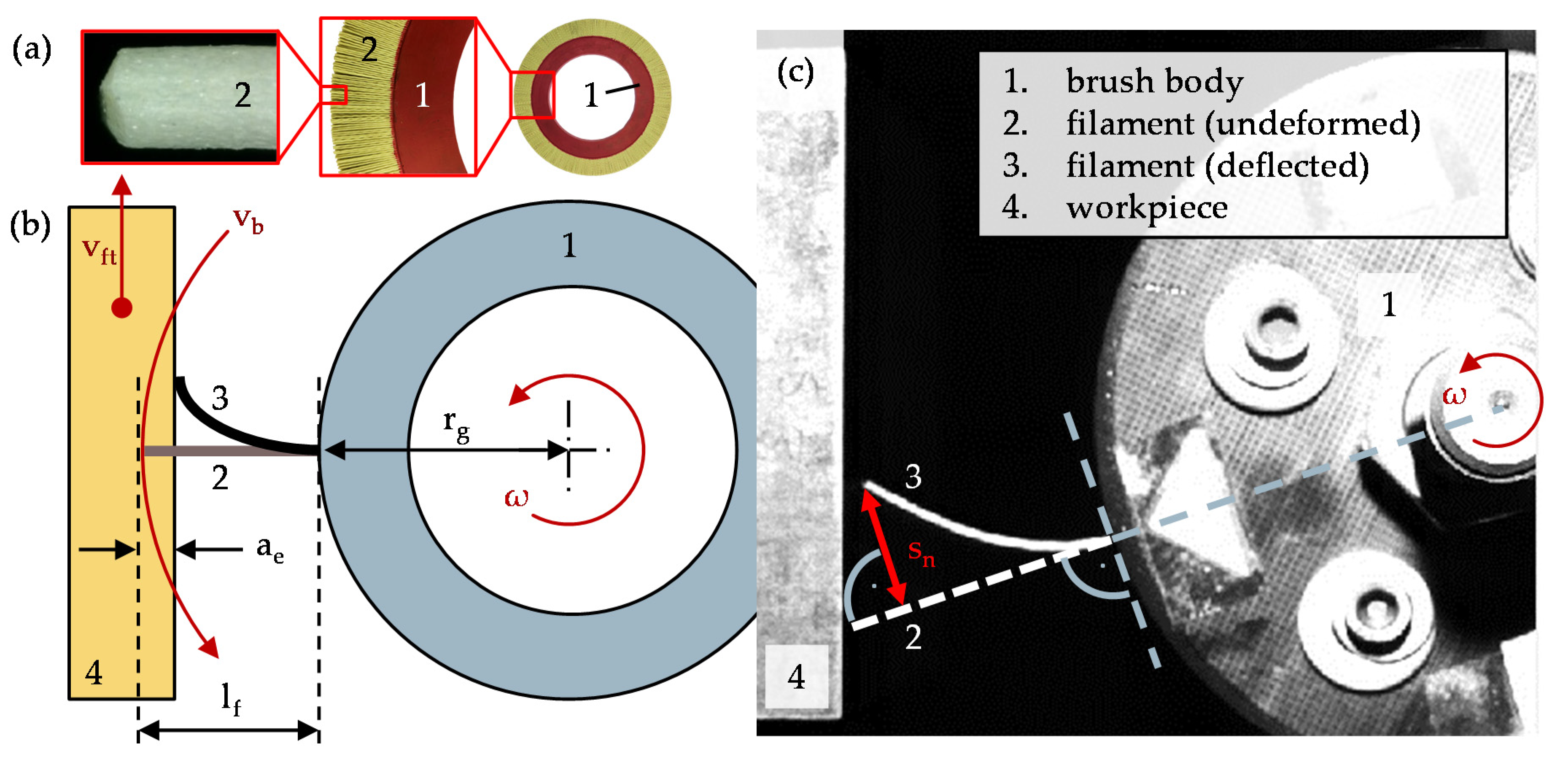
Brushing with bonded abrasives is an industrial manufacturing process, which is predominantly used for the deburring and rounding of metallic workpiece edges. Furthermore, it has gained importance in the finishing of technical surfaces, mainly for the reduction of the surface roughness [1,2,3]. The process is characterized by its flexible brushing tools (Figure 1), usually consisting of a cast epoxy brush body, to which abrasive filaments are attached (Figure 1a). These are composed of an extruded polymer matrix, normally polyamide 6.12, and bonded abrasive grains, normally silicon carbide (SiC) or aluminum(III) oxide (Al2O3). However, especially during the finishing of ceramic workpieces, hard abrasives, such as diamond or cubic boron nitride (cBN), are required [1,4].
The advantages of brushing with bonded abrasives are based on the high flexibility of the abrasive filaments, which allow for the adaptation to complex workpiece geometries, despite ordinarily shaped tools, and therefore the compensation of small geometric deviations of tools, workpieces and machine systems, as well as tool trajectories. Additional advantages are low process forces and temperatures, and also the potential utilization of pre-existing machine systems designed for grinding and milling operations. A considerable disadvantage of the process is the insufficient knowledge of the motion, the chipping, and the wear behavior of the abrasive filaments, with the result that industrial processes are typically based on experiential values, making predictions for new processes difficult [1,5,6].
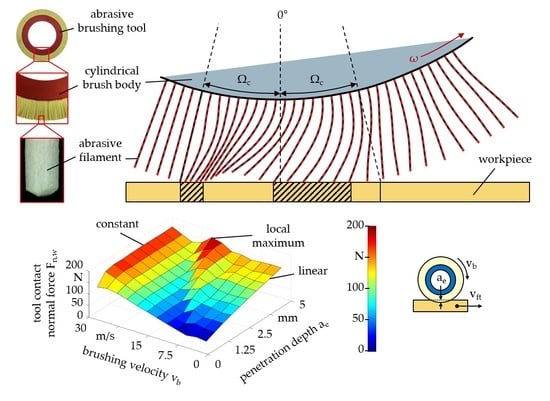
Regarding the tool specific parameters most relevant for achieving a low workpiece surface roughness, small filament diameters df, large filament lengths lf, and small grain sizes dg, are needed, whereas contrary tool specifications are required for high material removal rates [3,7,8]. A large brush body radius rg leads to a larger number of filaments Nf and to a more enhanced support between filaments than a small brush body radius rg, and thereby to more efficient brushing processes. The essential process parameters are the brushing velocity vb, the tangential feed rate vft, and the penetration depth ae (Figure 1b). Above all, the surface roughness of the workpieces can be successively reduced by multiple brushing cycles until a lower roughness limit is reached, which is primarily dependent on the tool specification. Therefore, a low surface roughness can also be achieved with gentle process parameters, specifically low brushing velocities vb, high tangential feed rates vft, and low penetration depths ae [3]. Furthermore, process heat can be dissipated by the use of cooling lubricant to prevent the melting of the abrasive filaments, which would affect the productivity adversely or even cause permanent tool damage. However, in some studies, a reduction of the productivity during brushing with cooling lubricant is mentioned, likely caused by a reduction of the effective Young modulus Ef of the abrasive filaments due to polyamide being prone to liquid absorption [2,3]. Within the scope of this article, productivity is defined as the rate of change of the work result, meaning the surface roughness or the material removal rate, while simultaneously considering the negative influence of tool wear.
Various studies confirm a significant dependence of the productivity on the applied contact forces, as high contact forces increase the penetration of the workpiece material by the abrasive grains [1,2,3,5,6,9]. To gain an understanding of the process behavior of abrasive filaments, technological investigations with single filaments and full brushing tools may be carried out, as well as numerical process simulations based on physical models. In both cases, the knowledge transfer between single-and multi-filament models is challenging and a focus of contemporary research [9]. For example, contact force measurements with single filaments at high brushing velocities vb are difficult (Figure 1c), due to low force values along with a high predisposition of the experimental equipment towards unwanted vibrations. Adversely, the use of numerical process models for the calculation of a multitude of interacting filaments is still limited due to long computation times [9].
Hence, the aim of this article is the introduction of a new method to correlate the numerically simulated contact forces of single abrasive filaments with the experimentally determined process forces of full brushing tools, the acquisition of which is relatively unproblematic. For this purpose, the contact impulse transmitted by the abrasive filaments onto the workpiece is calculated in order to avoid the use of error-sensitive smoothing algorithms and thus to increase the scope of application for numerically simulated brushing parameters.
2. Materials and Methods
The chosen case of application was the surface finishing of zirconium dioxide, partially stabilized with magnesium oxide (MgO-PSZ, or ZrO2 for simplicity), its main domains of application including dental and medical engineering as well as industrial furnace linings [10,11]. The previously surface-ground workpieces feature dimensions of 200 × 200 × 200 mm3 and an average roughness of Ra = 1.1 µm.
The brushing tools used were round brushes manufactured by C.Hilzinger-Thum GmbH and Co.KG, Tuttlingen, Germany, with a brush body radius of rg = 140 mm, a tool width of bb = 20 mm, a filament length of lf = 40 mm, a filament diameter of df = 1.18 mm and a filament density of ρf = 1.11 g/cm³. Due to the high hardness and the brittle machining behavior of ZrO2, abrasive filaments composed of polyamide 6.12 and bonded polycrystalline diamond with a grit size of 320 mesh and a mean grain size of dg = 29.2 µm were used [12]. Based on photographs of the brushing tools’ circumferences, an estimated number of abrasive filaments per tool of Nf = 10,500 ± 600 was determined. For this, a Hough transformation was applied to detect and count the circular filament tips of tool segments, extrapolating their quantity for the entire brushing tool.
The technological investigations were carried out on a plane and profile grinding machine of type Profimat MT 408 HTS, manufactured by Blohm Jung GmbH, Hamburg, Germany, and process forces were measured with a quartz three-component dynamometer of type 9257B, manufactured by Kistler Instrumente AG, Winterthur, Switzerland, to which the workpieces were attached. Because the workpieces were planar and edge contacts were not being investigated, only the process forces in the normal direction of the workpiece surface were evaluated; their arithmetic mean value over the processing time tp being defined as the tool contact normal force Fn,w. Despite the low heat conductivity of ZrO2, no cooling lubricant was used during brushing in order to decrease the number of possible influences on the measurement of process forces.
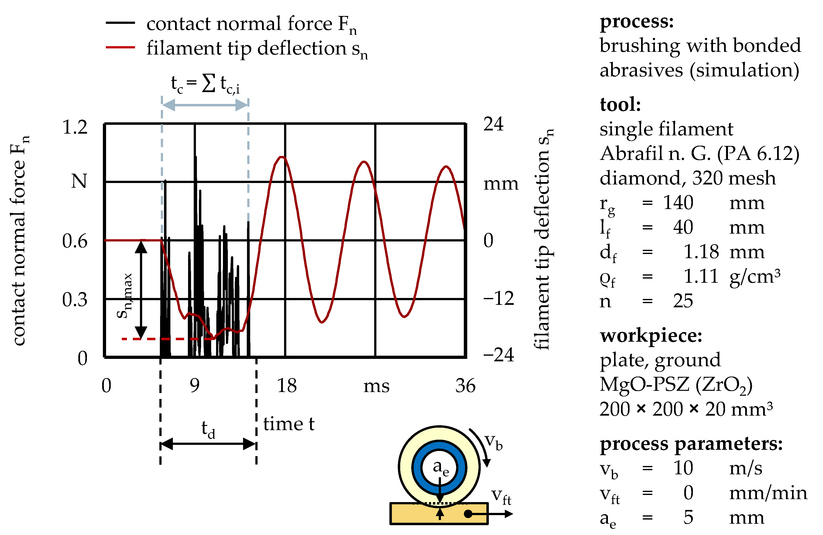
To simulate the deformations and the contact forces of abrasive filaments, a multi-body system based on the Lagrange formalism was implemented in MATLAB R2019b, developed by The MathWorks, Inc., Natick, Massachusetts, USA. Using spherical coordinates, the flexible filaments were subdivided into rigid segments, connected end-to-end by rotational springs and dampers. After the appropriate reduction of the degrees of freedom, the positions and the motions of the segments in three-dimensional space were distinctly characterized by their minimal coordinates, namely their polar angles φk and azimuth angles θk, as well as their respective angular velocities and accelerations. Incorporating the Lagrange function L, the kinetic energy Ekin, the potential energy Epot, the dissipation energy D, and the conservative momentum Mk,φ, a system of ordinary differential equations of second was formed, which could be solved numerically. Equation (1) shows the differential equation used to calculate the polar angle φk of an arbitrary single segment with index k, while the azimuth angle θk was obtained analogously [9].
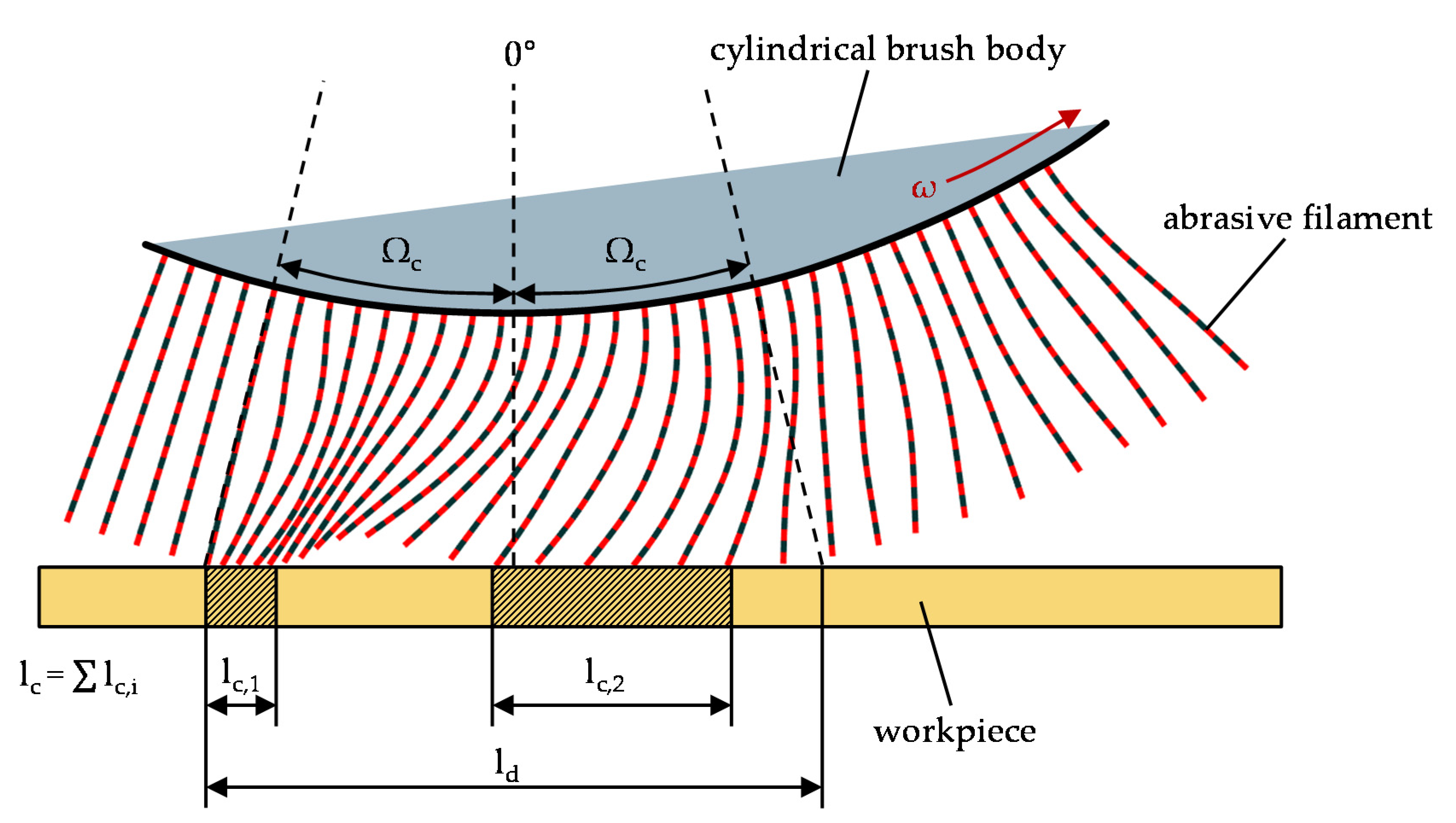
The results indicate that the calculated process forces do not vary significantly for segment numbers of n ≥ 25, so that n = 25 was chosen as a compromise between high accuracy and low computation time. By the introduction of a rotating brush body and a translationally moved workpiece in the form of boundary conditions, the contact between abrasive filaments and arbitrary workpieces can be simulated in three-dimensional space. To subsequently characterize the contact behavior, a nominal contact length ld was defined, which can be deduced from the contact angle Ωc (Figure 2). Depending on the tool specification and process parameters, abrasive filaments may exhibit dynamic oscillatory behavior following the initial workpiece contact, which leads to the bouncing of the filament tips on the workpiece surface. Therefore, the actual contact length lc was calculated as the overall sum of the single contact lengths lc,i.
Analogously to the nominal contact length ld and the actual contact length lc, the nominal contact time td and the actual contact time tc were calculated, within which a filament tip was moved across the respective distance. Both the contact length lc and the contact time tc can be calculated from the contact normal force Fn, under the consideration that time steps without a filament–workpiece contact yield a contact normal force of Fn = 0 N (Figure 3). Due to the contact time tc being highly dependent on the brushing velocity vb and the penetration depth ae, the contact time ratio εtc was introduced on the grounds of interpretability (Equation (2)). It corresponds to a dimensionless normalization of the contact time tc by the nominal contact time td and serves as a basis upon which to characterize filament motions as either striking (εtc → 0) or sweeping (εtc → 1).
It should also be noted that the contact time ratio εtc equals the analogously calculated contact length ratio εlc, assuming a constant time step width Δt. Nonetheless, the contact time ratio εtc was used within the scope of this article due to the contact normal impulse pn being based on the contact time tc and not the contact length lc (Equation (3)).
With regard to the dynamic oscillatory behavior of the abrasive filaments, the contact time ratio εtc is most likely a more robust measure than the previously established maximum filament tip deflection sn,max, meaning the maximum absolute value of the shortest distance between deflected filament tip and undeformed filament during the filament-workpiece contact [13] (Figure 1c). Its main disadvantage becomes apparent while studying the curve shape of the filament tip deflection sn over time t (Figure 3), which may fluctuate considerably during the workpiece contact, where the deflection maximum is located. However, the maximum filament tip deflection sn,max lacks usable information about the workpiece contact itself, which would be crucial in order to understand the effects of highly dynamic filament behavior on the productivity.
Further examination of the contact normal force Fn reveals that a meaningful maximum value is not easily deduced, because the curve shape is characterized by extreme peaks and a multitude of contact-free regions (Figure 3), which can be attributed to the dynamic oscillatory behavior of the abrasive filaments as well as to their complex deformation [13,14]. Potential smoothing algorithms, such as median or Gaussian filters, would thereby lead to significant deviations and consequently distort the curve shape. While the contact normal force Fn shows consistent, steadily increasing curve shapes at low brushing velocities vb [13], the described dynamic behavior necessitates novel methods of evaluation, especially for high, industrially relevant brushing velocities vb.
Therefore, the contact normal force Fn was converted into the contact normal impulse pn, (Equation (3)) [15]. Formally, the contact normal force Fn of a single abrasive filament was integrated over the contact time tc. Because contact forces for both the process model and after experimental data acquisition exist in the form of discrete values with distinct indices i, the overall sum of all values Fn,i and subsequent multiplication with the time step width Δt can be used for this purpose.
As for the inverse transform, dividing the contact normal impulse pn by the contact time tc yields the equivalent contact normal force (Equation (4)), which represents an arithmetic averaging of the contact normal force Fn over the contact time tc.
To further project this method, which is only valid for single abrasive filaments, onto full brushing tools, the contact normal impulse pn was multiplied with the estimated number of filaments Nf and the angular velocity ω to calculate the tool contact normal force Fn,w (Equation (5)).
Physically, the tool contact normal force Fn,w corresponds to the tool contact normal impulse pn,w transmitted by the brushing tool onto the workpiece over the course of a single second. It represents an extrapolation of a single abrasive filament while neglecting filament interactions, but shows robust behavior compared to typical smoothing algorithms if applied to abrasive filament contact forces.
3. Results
Utilizing the multi-body system based on the Lagrange formalism, a total of 120 contact simulations were computed, each modeling the contact between a single abrasive filament and a planar workpiece of ZrO2, while considering brushing velocities of vb ≤ 30 m/s and penetration depths of ae ≤ 5 mm. The tangential feed rate vft was not varied, as it was not expected to have an influence due to the plain workpiece geometry, no tangential or friction forces being investigated, and the tangential feed rate vft being several orders of magnitude smaller than the brushing velocity vb.
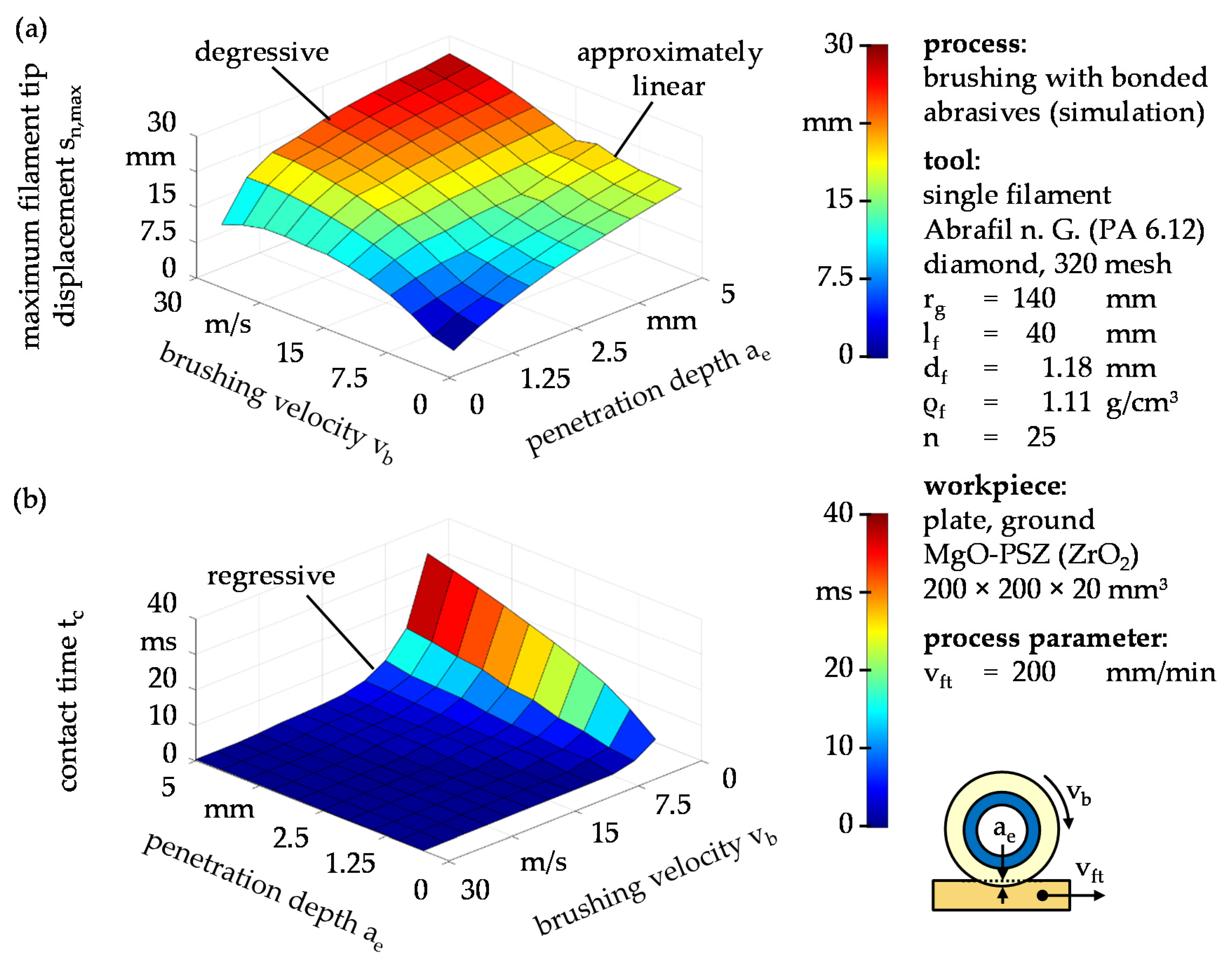
The maximum filament tip displacement sn,max, used to monitor dynamic oscillatory filament behavior during previous research [14], increases approximately linearly with the brushing velocity vb and degressively with the penetration depth ae (Figure 4a) but otherwise provides insufficient information about the filament–workpiece contact due to the absence of a time dependent component. The corresponding contact time tc shows a highly regressive decrease with increased brushing velocity vb (Figure 4b), although this effect is more prevalent for large penetration depths ae than for small penetration depths ae because of the increased contact angle Ωc (Figure 2). This implies that the brushing velocity vb has a considerably greater impact on the contact time tc, as well as on subsequently calculated parameters, than the penetration depth ae.
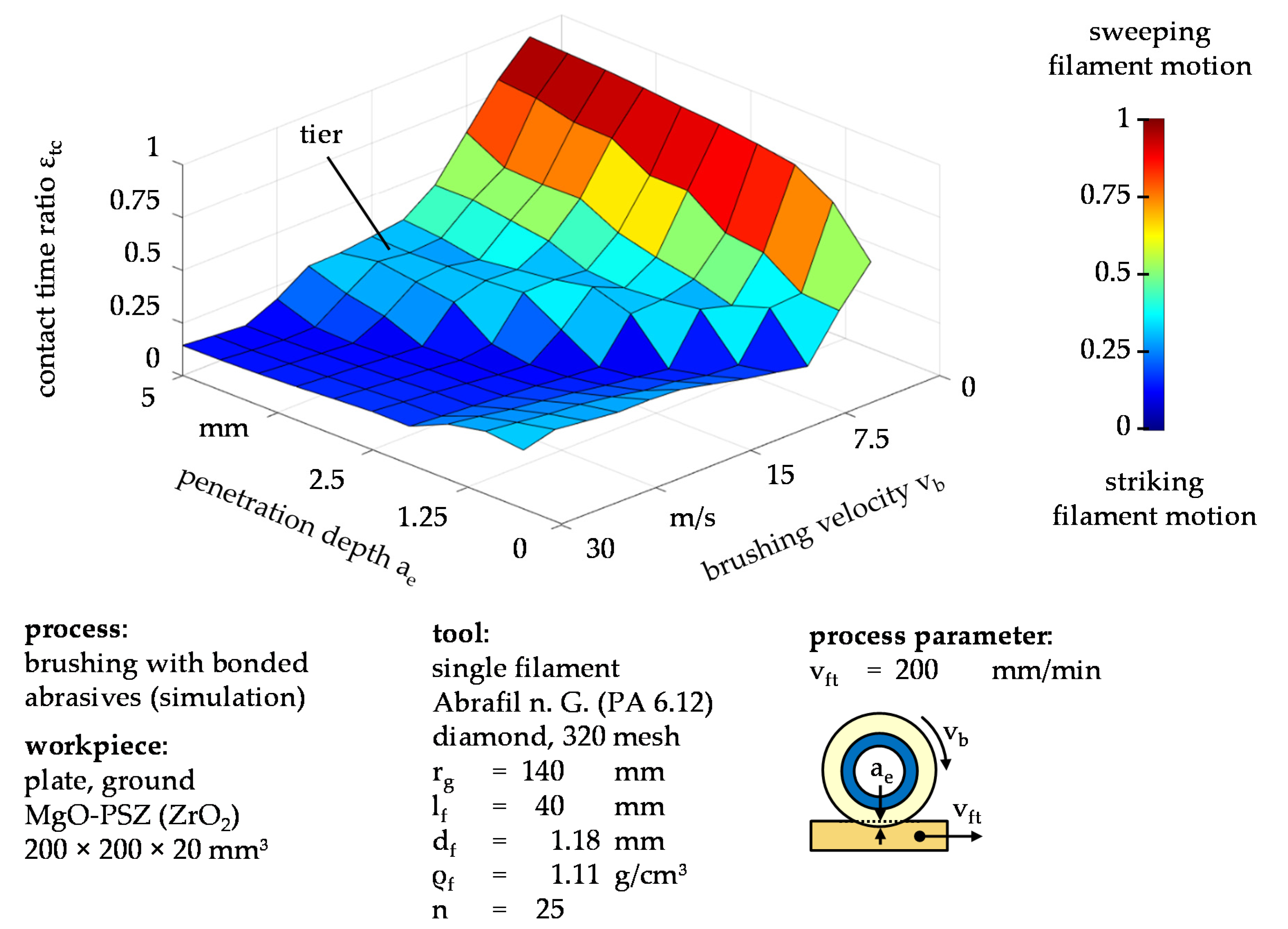
For a more suitable visualization, the contact time tc was divided by the nominal contact time td to calculate the contact time ratio εtc (Equation (2), Figure 5). Variation of the process parameters shows that high brushing velocities vb lead to primarily striking filament motions (εtc → 0) because abrasive filaments, deflected by an initial workpiece contact, are moved past the contact zone before they can swing back. In addition, an approximately proportional separating line between brushing velocity vb and penetration depth ae can be observed, below which filament motions are primarily striking, and above which the primarily sweeping region is characterized by a distinguishable tier.
In theory, dynamic oscillatory behavior and subsequent striking filament motions lead to an increase of the process forces and thereby to an increase of the material removal rate [16,17,18,19]. Although dynamic behavior can be both confirmed and controlled based on technological investigations, a positive influence on productivity remains to be confirmed. Nonetheless, the knowledge of the contact time ratio εtc might prospectively be utilized to predict the productivity of abrasive brushing processes. However, further technological investigations need to be carried out to verify this.
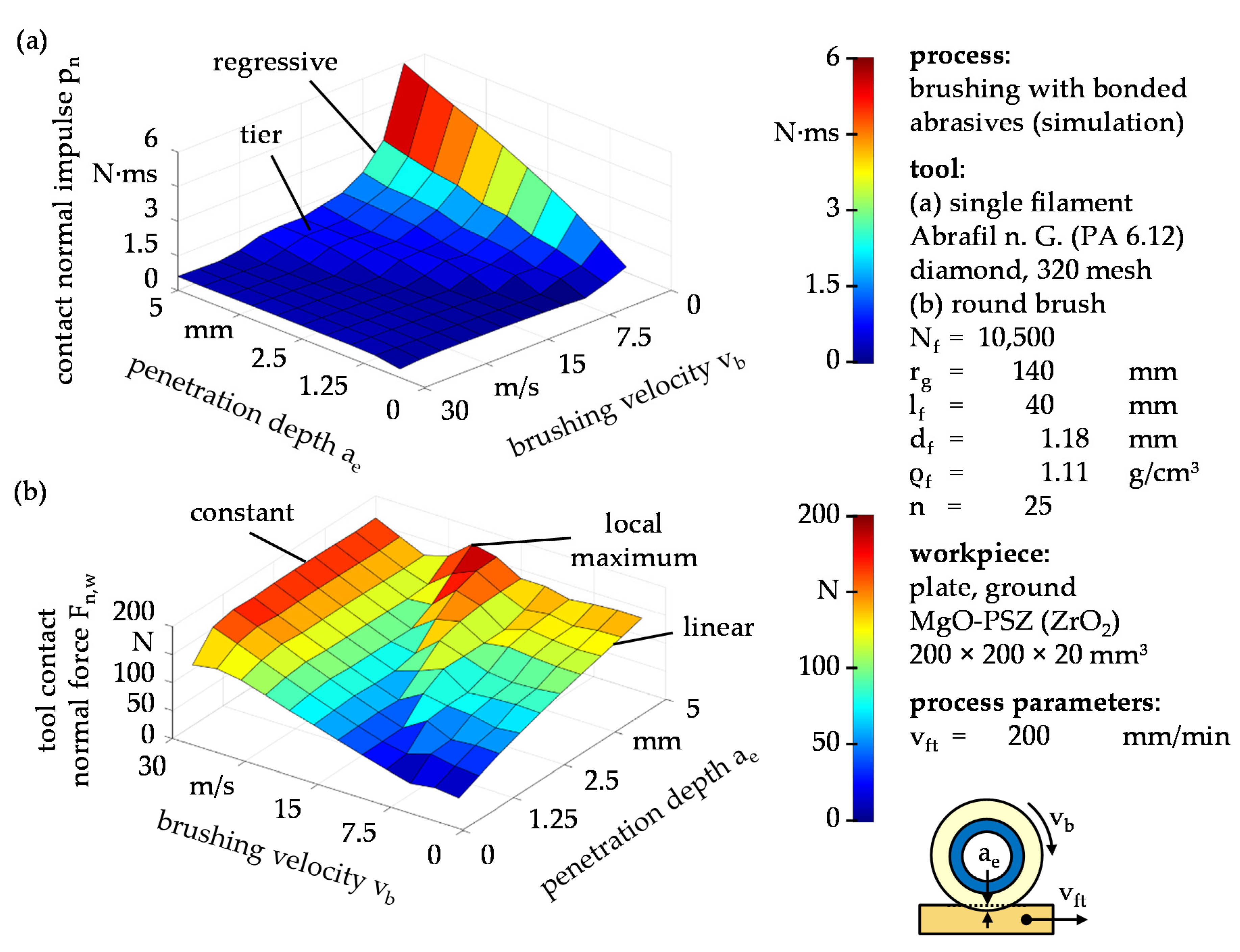
Comparing the contact normal impulses pn of a single abrasive filament for varied process parameters, a regressive dependence on the brushing velocity vb can be observed, particularly for high penetration depths ae (Figure 6a). Similar to the contact time ratio εtc, although less distinct, a tier is formed along the proportional line between brushing velocity vb and penetration depth ae, below which the contact normal impulse pn is low. Except for the tier, the contact normal impulse pn qualitatively resembles the contact time tc (Figure 4b) indicating that the contact normal force Fn affects the contact normal impulse pn considerably less than the contact time tc, Equation (3).
To explain the contradictory phenomenon where high brushing velocities vb lead to low impulse transmissions and therefore to decreased productivity, the tool contact normal force Fn,w is calculated with regard to angular velocity ω and the estimated number of filaments Nf (Equation (5)). Figure 6b illustrates that high brushing velocities vb amount to a higher tool contact normal force Fn,w than low brushing velocities vb, because the total number of filament–workpiece contacts increases more rapidly with increasing angular velocity ω than the impulse transmitted by a single filament decreases. Equally noticeable is that the tool contact normal force Fn,w only shows a linear increase with the penetration depth ae for low brushing velocities vb. This gives the assumption that, contrary to previous research, high brushing velocities vb, together with large penetration depths ae, may lead to unproductive brushing processes due to both parameters substantially contributing to tool wear [1,3,14].
Moreover, the tier observed in Figure 5 and Figure 6a results in a local maximum of the tool contact normal force Fn,w (Figure 6b) likely caused by a second contact area towards the end of the filament–workpiece contact. This local maximum might be targeted by means of appropriate process design, in order to maximize the impulse transmission with only moderate brushing velocities vb. To what extent this phenomenon has an impact on productivity remains to be determined by additional technological investigations.
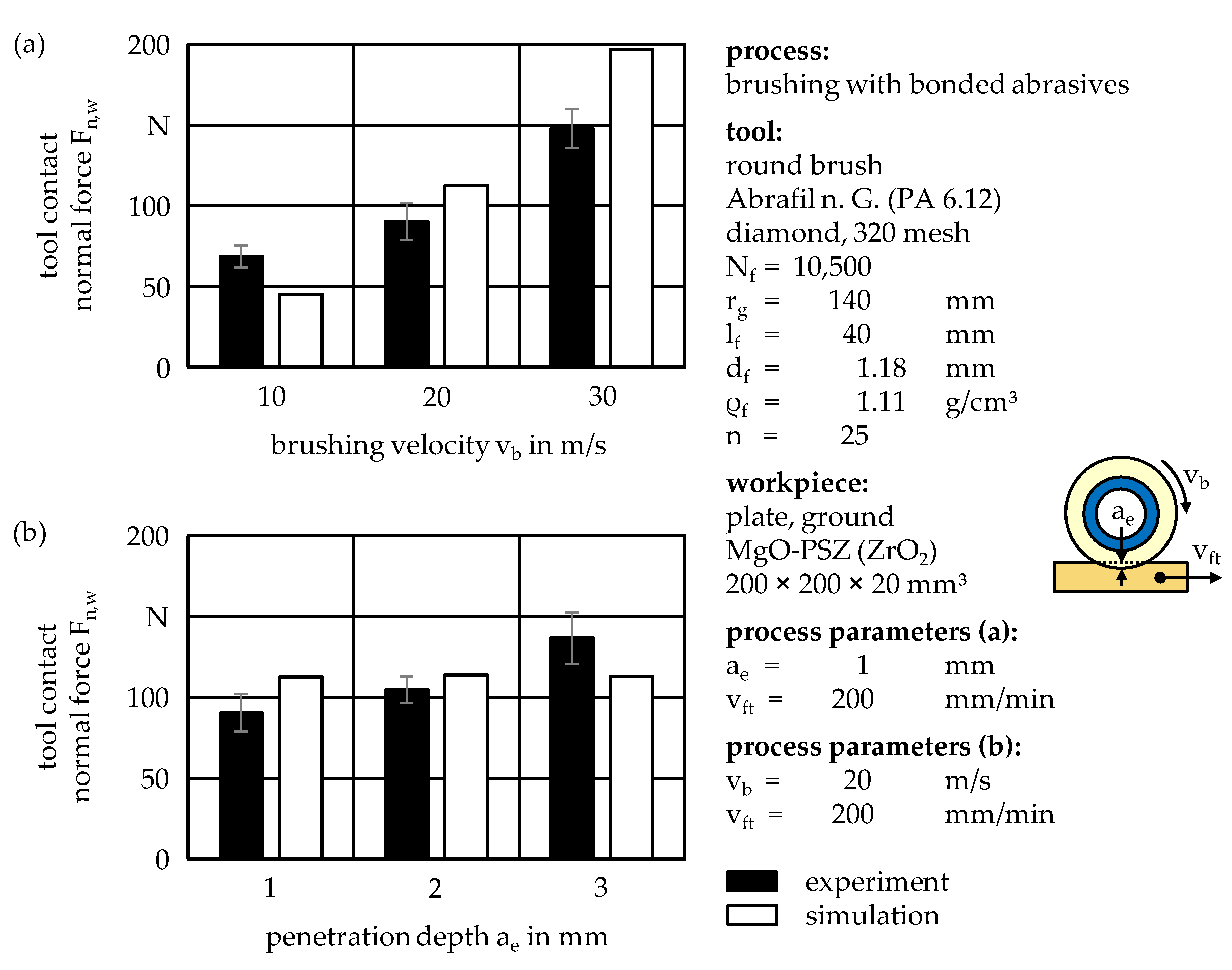
Comparing the computed tool contact normal force Fn,w with the experimentally determined values, the variation of the brushing velocity vb shows that the fundamental behavior is reflected by the model, although all investigated brushing velocities vb lead to deviations outside of the experimentally determined standard deviation (Figure 7a). Regarding the penetration depth ae, the experimentally determined results show a dependence that is not predicted by the model within the investigated parameter boundaries (Figure 7b).
In both cases, the most plausible cause of error may be the neglection of the filament interactions, because the computation of the tool contact normal force Fn,w is solely based on the extrapolation of a single abrasive filament. For large penetration depths ae, it is expected that abrasive filaments with either striking or sweeping motion behavior may be pressed onto the workpiece surface by neighboring filaments, which would increase the impulse transmission and thereby the process forces. Additional possible error causes could be undetected manufacturing inaccuracies of the brushing tools as well as a slight waviness of the abrasive filaments purposely induced by the manufacturer but not considered for the model, for which perfectly cylindrical filaments are assumed. Furthermore, the filament–workpiece contact is merely modeled for undeformed abrasive filaments, starting shortly before the initial contact in order to minimize computation times, whereas subsequent tool rotations and filament workpiece contacts at high brushing velocities vb might cause the abrasive filaments to already be deflected.
4. Discussion
Within the scope of this article, a new method is introduced to correlate the numerically simulated contact forces of single abrasive filaments with the experimentally determined process forces of full brushing tools by interim calculation of the contact impulse. Based on the presented work, the following conclusions can be drawn:
- High brushing velocities vb may not compulsorily lead to maximum productivity, but less aggressive process parameters might yield more productive results instead, considering that the productivity is affected negatively by tool wear.
- Despite a variety of simplifications—which include the extrapolation of the total number of filaments Nf as well as the assumption of constant filament diameters df and filament lengths lf,—measured and modeled tool contact normal forces Fn,w are in the same order of magnitude.
- During the variation of the penetration depth ae in particular, discrepancies between measured and modeled tool contact normal forces Fn,w arise.
- As a main cause of error, neglected filament interactions are suggested.
Due to the model inaccuracies, at this point in time, the model should only be applied under the conditions of brushing tools without densely packed abrasive filaments and small penetration depths ae. However, as industrial brushing processes usually require small penetration depths of ae ≤ 1 mm, the model is estimated to be partially applicable.
Additionally, the contact time ratio εtc is introduced in order to quantify the possibly dynamic motion behavior of single abrasive filaments. This allows for a distinction between primarily sweeping and primarily striking filament motions and might be used for future research as an easily computed means to predict productivity while considering tool wear.
5. Outlook
Prospectively, technological investigations are planned to verify the influence of the tool contact normal force Fn,w and the contact time ratio εtc on the productivity, meaning on the rates of change of the surface roughness and the material removal rate. Furthermore, the interactions between filaments will be modeled similarly to the filament–workpiece contact in order to explain the discrepancies between the current physical model and the experimental results. For this purpose, the multi-body system will be compared with, and possibly superseded by, commercially available software employing the discrete element method, granting a compromise between modeling accuracy and computation time. The finite element method will also be used to analyze the wear-related change of the abrasive filament tip shape over time and its influence on the productivity of abrasive brushing processes.
Further research should be carried out, investigating not only the process forces exerted onto the surfaces of planar workpieces, but also workpieces with complex shapes and especially workpiece edges, as edge deburring still remains the most important field of application for abrasive brushing tools in industrial finishing processes, particularly for metallic workpieces. The current implementation of the multi-body system permits the investigation of both complex workpiece shapes and their edges by utilizing polynomial splines of arbitrary degree, including them as boundary conditions while solving the system of differential equations obtained from the Lagrange formalism. Of equal industrial importance is the comparison of round brushing tools, as described within the scope of this article, with brushing tools comprising filaments with axial orientation. Round brushing tools were chosen for this research project because of their penetration depth ae being independent from the brushing velocity vb, whereas other tool shapes may lead to a reduction of the penetration depth ae and thus the tool contact normal force Fn,w, with increasing brushing velocity vb due to centrifugal forces deflecting the filaments outwards, necessitating force controlled brushing processes as opposed to geometrically planned tool paths.
Author Contributions
Conceptualization, A.H., E.U.; methodology, E.U.; software, A.H.; validation, A.H.; formal analysis, A.H.; investigation, A.H.; resources, A.H.; data curation, A.H.; writing—original draft preparation, A.H.; writing—review and editing, E.U.; visualization, A.H.; supervision, E.U.; project coordination, E.U.; funding acquisition, E.U. All authors have read and agreed to the published version of the manuscript.
Funding
This research was funded by Deutsche Forschungsgemeinschaft (DFG) within the scope of the project “Analyse des Zerspan- und Verschleißverhaltens beim Bürstspanen mit abrasivem Medium sprödharter Werkstoffe”, project number 392312434. The authors kindly thank the funder for their support.
Institutional Review Board Statement
Not applicable.
Informed Consent Statement
Not applicable.
Data Availability Statement
Not applicable.
Conflicts of Interest
The authors declare no conflict of interest.
References
- Uhlmann, E.; Sommerfeld, C.; Renner, M.; Baumann, M. Bürstspanen von Profilen. Werkstattstech. Online 2017, 107, 238–243. [Google Scholar]
- Hochschild, L. Finishbearbeitung Technischer Oberflächen aus Gehärtetem Stahl unter Verwendung von Rundbürsten mit Schleiffilamenten. Ph.D. Thesis, Technical University Berlin, Berlin, Germany, 2018. [Google Scholar]
- Uhlmann, E. Flexible Feinstbearbeitung von Funktionsflächen mit alternativen Werkzeugkonzepten (FlexFeinst). In Schlussbericht zu IGF-Vorhaben Nr. 19601 N/1; Technical University Berlin, Institute for Machine Tools and Factory Management: Berlin, Germany, 2020. [Google Scholar]
- Rentschler, J.; Muckenfuß, G. Neue Anwendungsmöglichkeiten durch hochtemperaturbeständige Schleiffilamente in der Oberflächenbearbeitung. In Jahrbuch Honen, Schleifen, Läppen und Polieren; Hoffmeister, H.W., Denkena, B., Eds.; Vulkan: Essen, Germany, 2013; pp. 387–403. [Google Scholar]
- Przyklenk, K. Bestimmung des Bürstenverhaltens anhand einer Einzelborste. Berichte aus dem Fraunhofer-Institut für Produktionstechnik und Automatisierung (IPA), Stuttgart, Fraunhofer-Institut für Arbeitswirtschaft und Organisation (IAO), Stuttgart und Institut für Industrielle Fertigung und Fabrikbetrieb der Universität Stuttgart Nr. 87; Warnecke, H.J., Bullinger, H.-J., Eds.; Springer: Berlin/Heidelberg, Germany, 1985. [Google Scholar]
- Uhlmann, E.; Lypovka, P.; Sommerfeld, C.; Bäcker, C.; Dethlefs, A.; Hochschild, L. Abrasives Bürsten. Werkstatt Betr. 2014, 4, 70–72. [Google Scholar]
- Landenberger, D. Flexible Feinbearbeitung für die Refabrikation von Automobilkomponenten. Ph.D. Thesis, University of Bayreuth, Bayreuth, Germany, 2007. [Google Scholar]
- Landenberger, D.; Steinhilper, R.; Rosemann, B. Verbesserung der Oberflächengüte durch Bürstspanen. VDI-Z 2007, 149, 7–69. [Google Scholar]
- Sommerfeld, C.; Uhlmann, E.; Hoyer, A. Modelling of Brushing Processes. In Proceedings of the ASME 2019 14th International Manufacturing Science and Engineering Conference, Erie, PA, USA, 10–14 June 2019; pp. 1–11. [Google Scholar]
- Hao, L.; Lawrence, J.; Chian, K.S. Osteoblast Cell Adhesion on a Laser Modified Zirconia Based Bioceramic. J. Mater. Sci. Mater. Med. 2005, 16, 719–726. [Google Scholar] [CrossRef] [PubMed]
- Forkas-Tsentzeratos, G. Influence of the Surface and Heat Treatment on the Flexural Strength and Reliability of Y-TZP Dental Ceramic. Ph.D. Thesis, Medicinal Faculty of the Eberhard Karls University, Tübingen, Germany, 2010. [Google Scholar]
- Federation of European Producers of Abrasives. FEPA-Standard 42-2: Grains of Fused Aluminium Oxide, Silicon Carbide and Other Abrasive Materials for Bonded Abrasives and for General Applications Microgrits F230 to F2000; Federation of European Producers of Abrasives: Paris, France, 2006. [Google Scholar]
- Uhlmann, E.; Sommerfeld, C. Dynamic Analysis of Abrasive Filaments in Contact with Different Workpiece Geometries. Int. J. Autom. Technol. 2018, 6, 892–900. [Google Scholar] [CrossRef]
- Hoyer, A.; Uhlmann, E. Dynamik beim Bürstspanen. Werkstattstech. Online 2020, 110, 478–484. [Google Scholar] [CrossRef]
- Grote, H.-K.; Feldhusen, J. Dubbel–Taschenbuch für den Maschinenbau, 23rd ed.; Springer: Berlin/Heidelberg, Germany, 2011; p. B28. [Google Scholar]
- Vanegas-Useche, L.V.; Abdel-Wahab, M.M.; Parker, G.A. Theoretical Model for the Free-Flight Behavior of the Bristle of an Oscillatory Gutter Brush for Road Sweeping. In Proceedings of the 11th International Conference on Vibration Engineering, Timisoara, Romania, 27–30 September 2005; pp. 83–90. [Google Scholar]
- Vanegas-Useche, L.V.; Abdel-Wahab, M.M.; Parker, G.A. Theoretical Model for the Dynamics of an Unconstrained Cutting Brush of a Street Sweeper. In Proceedings of the 8th Biennial ASME Conference on Engineering Systems Design and Analysis, Turin, Italy, 4–7 July 2006; pp. 431–440. [Google Scholar]
- Vanegas-Useche, L.V.; Abdel-Wahab, M.M.; Parker, G.A. Dynamics of an Unconstrained Oscillatory Flicking Brush for Road Sweeping. J. Sound Vib. 2007, 3–5, 778–801. [Google Scholar] [CrossRef]
- Vanegas-Useche, L.V.; Abdel-Wahab, M.M.; Parker, G.A. Dynamics of a Freely Rotating Cutting Brush Subjected to Variable Speed. Int. J. Mech. Sci. 2008, 4, 804–816. [Google Scholar] [CrossRef]
Figure 1.
Brushing with bonded abrasives; (a) round brush with diamond grains; (b) contact proportions during brushing, schematically depicted on the basis of a single abrasive filament; (c) technological investigations with a single abrasive filament during workpiece contact, capturing the filament tip deflection sn.

Figure 2.
Simulation of the deflection of a single abrasive filament during workpiece contact.

Figure 3.
Contact normal force Fn and filament tip displacement sn over time t.

Figure 4.
Filament–workpiece contact characteristics; (a) maximum filament tip displacement sn,max and (b) contact time tc for different brushing velocities vb and penetration depths ae.
Figure 4.
Filament–workpiece contact characteristics; (a) maximum filament tip displacement sn,max and (b) contact time tc for different brushing velocities vb and penetration depths ae.

Figure 5.
Contact time ratio εtc for different penetration depths ae and brushing velocities vb.

Figure 6.
Extrapolation of filament–workpiece contact forces; (a) contact normal impulse pn and (b) tool contact normal force Fn,w for different brushing velocities vb and penetration depths ae.
Figure 6.
Extrapolation of filament–workpiece contact forces; (a) contact normal impulse pn and (b) tool contact normal force Fn,w for different brushing velocities vb and penetration depths ae.

Figure 7.
Tool contact normal force Fn,w for different (a) brushing velocities vb and (b) penetration depths ae.
Figure 7.
Tool contact normal force Fn,w for different (a) brushing velocities vb and (b) penetration depths ae.

Publisher’s Note: MDPI stays neutral with regard to jurisdictional claims in published maps and institutional affiliations. |
© 2021 by the authors. Licensee MDPI, Basel, Switzerland. This article is an open access article distributed under the terms and conditions of the Creative Commons Attribution (CC BY) license (https://creativecommons.org/licenses/by/4.0/).
Share and Cite
MDPI and ACS Style
Uhlmann, E.; Hoyer, A. Modeling of Contact Forces for Brushing Tools. Ceramics 2021, 4, 397-407. https://0-doi-org.brum.beds.ac.uk/10.3390/ceramics4030029
AMA Style
Uhlmann E, Hoyer A. Modeling of Contact Forces for Brushing Tools. Ceramics. 2021; 4(3):397-407. https://0-doi-org.brum.beds.ac.uk/10.3390/ceramics4030029
Chicago/Turabian StyleUhlmann, Eckart, and Anton Hoyer. 2021. "Modeling of Contact Forces for Brushing Tools" Ceramics 4, no. 3: 397-407. https://0-doi-org.brum.beds.ac.uk/10.3390/ceramics4030029