Article

Study on an Energy-Harvesting Magnetorheological Damper System in Parallel Configuration for Lightweight Battery-Operated Automobiles

Department of Mechanical Engineering, California State University, Fullerton, CA 92831, USA
*
Author to whom correspondence should be addressed.
Submission received: 14 May 2020 / Revised: 19 June 2020 / Accepted: 23 June 2020 / Published: 1 July 2020

Abstract

:
Suspension dampers are extremely critical for modern automobiles for absorbing vibrational energy while in operation. For years now, the viscous passive damper has been dominant. However, there is a constant need to improve and revolutionize the damping technology to adapt to modern road conditions and for better performance. Controlled shock absorbers capable of adapting to uneven road profiles are required to meet this challenge and enhance the passenger comfort level. Among the many types of modern damping solutions, magnetorheological (MR) dampers have gained prominence, considering their damping force control capability, fast adjustable response, and low energy consumption. Advancements in energy-harvesting technologies allow for the regeneration of a portion of energy dissipated in automotive dampers. While the amount of regenerated energy is often insufficient for regular automobiles, it could prove to be vital to support lightweight battery-operated vehicles. In battery-operated vehicles, this regenerated energy can be used for powering several secondary systems, including lighting, heating, air conditioning, and so on. This research focuses on developing a hybrid smart suspension system that combines the MR damping technology along with an electromagnetic induction (EMI)-based energy-harvesting system for applications in lightweight battery-operated vehicles. The research involves the extensive designing, numerical simulation, fabrication, and testing of the proposed smart suspension system. The development of the proposed damping system would help advance the harvesting of clean energy and enhance the performance and affordability of future battery-operated vehicles.

1. Introduction

Suspension dampers have played a significant role in the automobile industry for years and are a crucial part of the modern-day commute. For years now, the viscous passive damper has been dominant in the automobile industry [1]. However, with the improvement of vehicle performance and unpleasant road conditions, there is a constant need to improve and revolutionize the damping technology [2]. Controlled shock absorbers, capable of adapting to uneven road profiles, are required to meet this challenge and enhance the passenger comfort level [3]. Controlled shock absorbers can be classified into active and semi-active type suspension systems. The active suspension systems use an external power source to improve the controllability and responsiveness of the dampers to external disturbances [4]. The active systems add complexity, increase cost and weight, and often have reliability issues [5].
On the other hand, semi-active suspension systems use only a small source of power to moderate the damping and stiffness properties. The adjustable damping in the semi-active systems is achieved by different design techniques, including magnetorheological (MR) dampers, electrorheological (ER) dampers, and solenoid valve-based dampers [6]. Among them, MR dampers have gained significant attention from researchers, considering their damping force control capability, fast adjustable response, and comparatively low energy consumption [7]. The MR damper consists of magnetic particles suspended in a viscous liquid whose rheological properties can be altered with the application of an external magnetic field [8]. MR dampers require external energy to alter the magnetic field and excite the suspended magnetic particles, thereby improving the vibration damping [9].
Advancements in energy-harvesting technologies provide an option to regenerate a portion of energy dissipated in automotive dampers [10]. These energy-harvesting technologies allow savings of 2–10% of the total fuel consumption in the vehicle [11]. While the amount of regenerated energy is often insufficient for regular automobiles, it could prove to be vital for improving the performance of lightweight battery-operated vehicles [12]. In battery-operated vehicles, this regenerated energy can be used for powering several secondary systems, including lighting, heating, air conditioning, and so on. One of the most popular methods to harvest the energy from any system is using piezoelectricity. The principle of piezoelectric conversion is that, when subject to a mechanical strain, piezoelectric materials become polarized. Therefore, this characteristic of this material is used to convert voltage from vibrations [13] directly. Regrettably, the positioning speed of piezoelectric-based arrangements is limited by the lowest structural vibrational frequency, because structural vibrations become considerable at frequencies close to the resonant frequency, and can cause substantial positioning errors [13]. Moreover, the high-temperature sensitivity of piezoelectricity is also a significant limitation.
Furthermore, the energy-harvesting technologies can be classified into two categories based on the mechanism used: (1) mechanical transmission and (2) electromagnetic induction (EMI). The mechanical transmission-based energy generators use a rotary mechanism to convert the linear vibration into oscillatory motion, such as rack and pinion, ball screw, hydraulic regenerative systems, and so on [14]. Furthermore, the system uses rotational permanent magnets to harvest energy. The second category of energy-harvesting technology uses an electromagnetic induction (EMI) device to generate voltage from the relative motion of permanent magnets and coils. It is widely agreed that EMI-based energy-harvesting technologies are more efficient and reliable compared to the mechanical transmission-based harvesters [15].
In recent years, there has been a growing interest in coupling the MR dampers with the energy-harvesting technologies [12,16,17]. Cho et al. proposed a special structure of an EMI device to be used with an MR damper [18]. They experimentally investigated a smart passive control system comprising an MR damper and an EMI device to generate electrical power [18]. Choi and Wereley studied the feasibility and effectiveness of a self-powered MR damper using a spring–mass EMI device [19]. Sapiński established a permanent magnet power generator for MR dampers; the designed vibration generator consisted of a special arrangement and a foil-wound coil, and the numerical analysis and experiment were carried out to investigate the magnetic field distribution and efficiency of the generator [20].
Currently, most existing coupled suspension designs have the MR damper and the energy-harvesting modules in a series configuration. However, a series configuration has several limitations, including complex design, difficulty of maintenance, limited stroke length, and reduced damping performance. These limitations can be overcome by arranging the system in a parallel configuration which allows tailored designs, easy removal and maintenance, and results in improved performance.
The motivation of the current research is to overcome the existing limitations of MR dampers, coupled with the energy-harvesting module in a series configuration. Additionally, the ongoing growth and future potential of battery-operated vehicles have opened up several performance-related issues. This research focuses on studying the feasibility of a suspension system that combines the MR damping technology along with an electromagnetic induction (EMI)-based energy-harvesting system in a parallel configuration for application in lightweight battery-operated vehicles. The research also uses a predictive analytical model of the energy-harvesting system to predict the voltage generation. The research involves the extensive designing, numerical simulation, fabrication, and testing of the proposed smart suspension system.
An analytical model is developed using the fundamentals of vibrations to calculate the output energy of the energy-harvesting magnetorheological dampers. The free-body diagram of all the three dampers is constructed, and the damping forces acting on the systems are analyzed. This model is formulated using MATLAB/Simulink software to evaluate the equations used in the model. The design of the energy-harvesting magnetorheological dampers is developed using the CATIA V5 CAD tool. From this design, a prototype of the damper is fabricated. An in-house testing setup is built for testing this prototype. This prototype is tested for various parameters, such as damping force, velocity, and induced voltage. The prototype and the analytical model are validated.

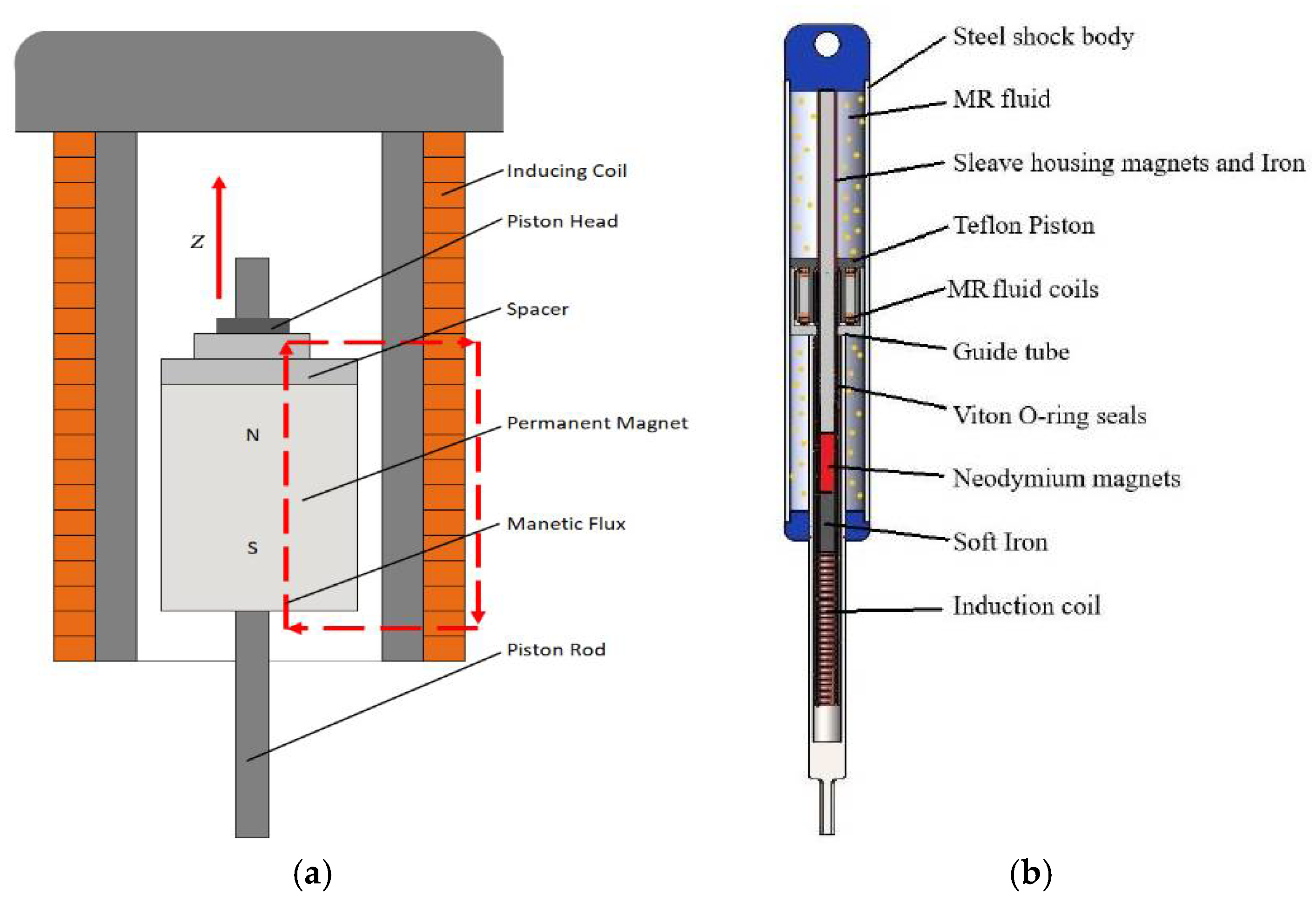
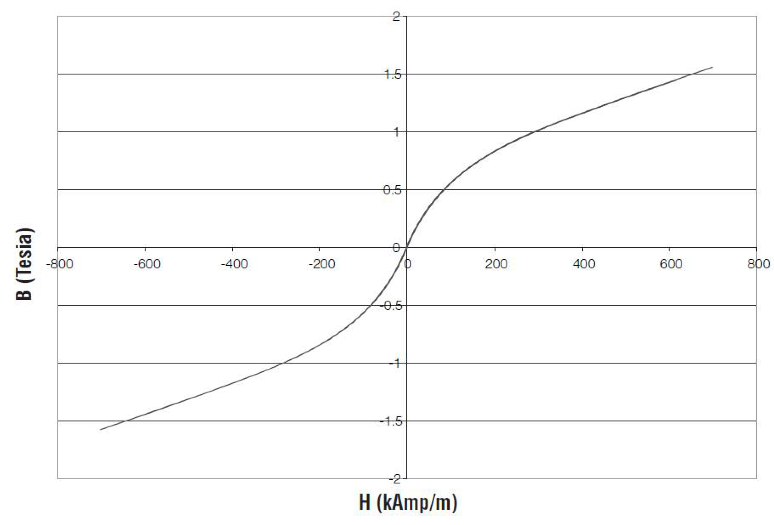
2. Analytical Modeling of Energy-Harvesting Module

Induced voltage and magnetic flux can be found from the following equations [4]. The terms used in the equations are given in Table 1. Efficiency factor ( η d ) is introduced to accommodate for the friction involved in the assembly while under oscillations. Friction ultimately causes a reduction in the displacement and speed of the damper during actuation. Due to this reduction, the movement of the magnet is decreased, which confines the power generation.
ϕ g = B r e m   τ m   μ 0   H c   A g 2 g   B r e m   + τ m   μ 0   H c   (   A g / A m )
  A g = 2 π ( s + l m + g 2 ) ( τ τ m 3 )
  A m = π   ( ( s + l m ) 2 s 2 )
E = N   g   π τ sin ( π τ   z + θ ) d z d t × η d
As the proposed damper is a downscaled version of the actual system, it is recommended to keep in mind the scaling laws. There are two types of scaling laws: (1) depends on the size of the physical objects and (2) involves both the size and material properties of the system. The project involves energy harvesting; therefore, the miniaturization of the EMI module needs to be considered. In a current-carrying wire in a magnetic field, for a given current density, the current i is proportional to the cross-sectional area of the wire [21]. Therefore, whenever a downscale is occurring, the cross-sectional area of the wire decreases in the order of square roots. So, to harvest more current from the magnetism, the length of the wire needs to be increased. To achieve that, a higher number of turns of inducing coil are required. Table 2 shows the values of various parameters of the energy-harvesting system used in this study.

3. MATLAB/Simulink Model

The MATLAB/Simulink model, based on the energy-harvesting equations, is attained as shown in Figure 1. The model starts with the equation of the cross-section area of the magnet. It requires the values of the diameter of the shaft and the width of the magnet. The second section is for finding the surface area of the cylindrical air gap, which requires the details of the length of the air gap between the piston rod and the permanent magnet array, magnet thickness, spacer thickness, the diameter of the shaft, and the width of the magnet. Furthermore, these findings are included in the equation of magnetic flux ( ϕ g ) . Based on the above values, the MATLAB/Simulink model can predict the induced voltage ( E ) .

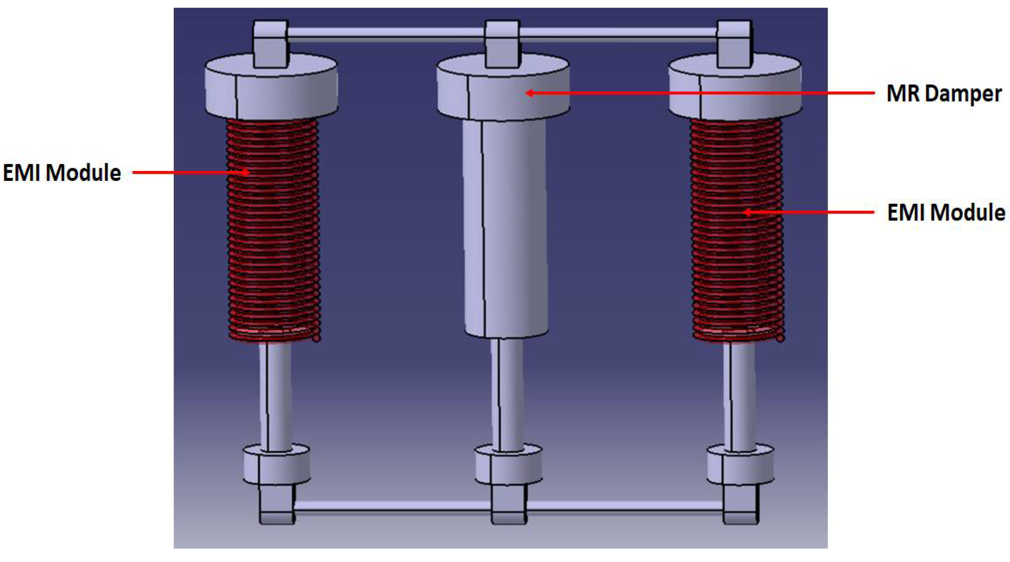
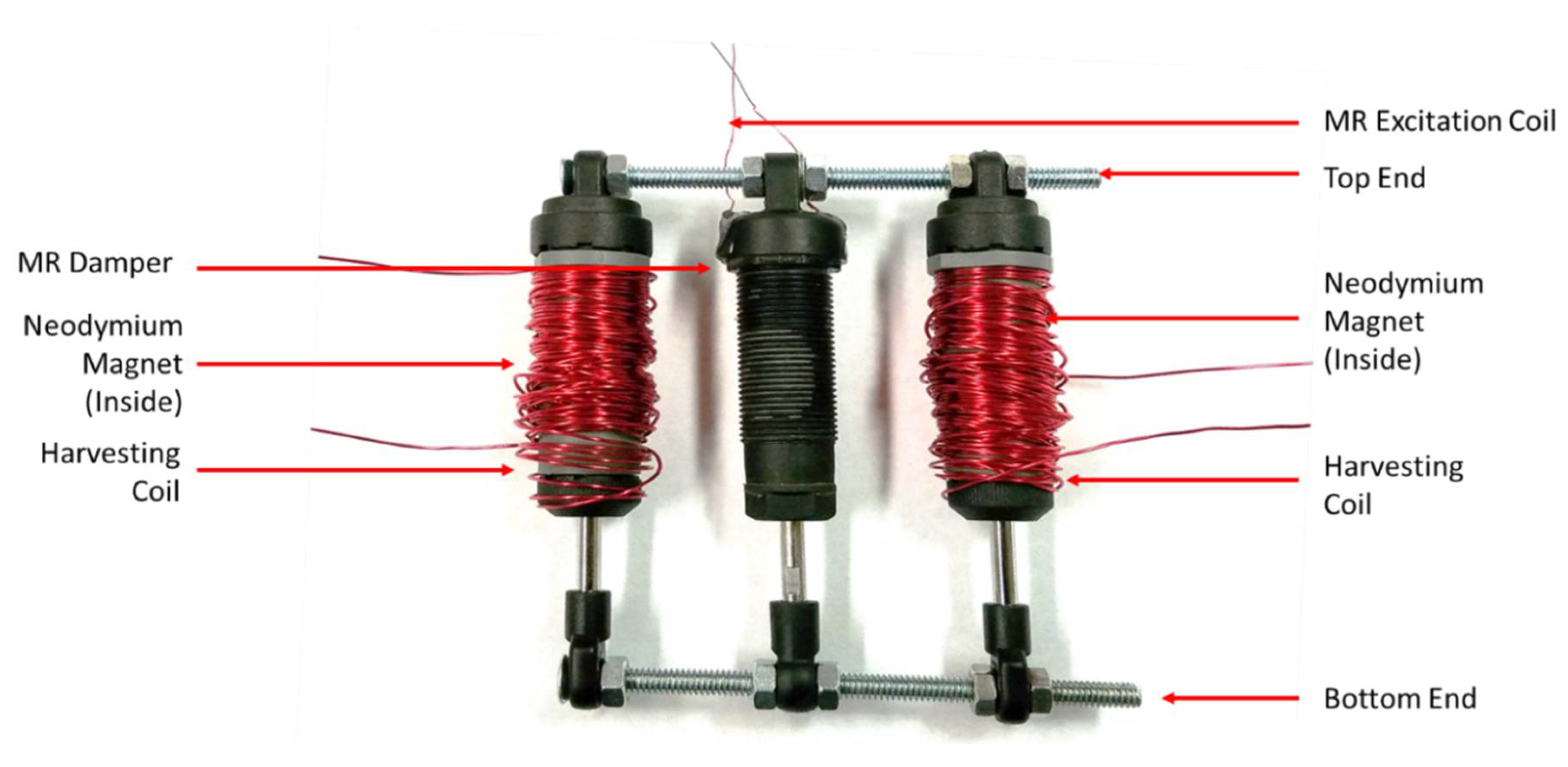
4. Energy-Harvesting Magneto-Rheological Suspension—Prototype Design

The CATIA V5 design modeling software program is used to model the proposed damper. Both the dampers on the side (energy harvesting module) consist of a copper generation coil and a neodymium N48 magnet inside. The schematic of the energy-harvesting module is shown in Figure 2a. Figure 2b shows the cross-sectional view of the MR damper. The energy-harvesting magnetorheological suspension prototype design in the parallel configuration is shown in Figure 3. The center damper has MR fluid inside it. Both the ends of MR damper and energy-harvesting modules are connected to the common beam. Therefore, any uneven profile coming from the bottom side can be equally distributed. The purpose of the MR damper is to damp the uneven vibrations. The EMI module generates energy, which can be further utilized for any other auxiliary systems.

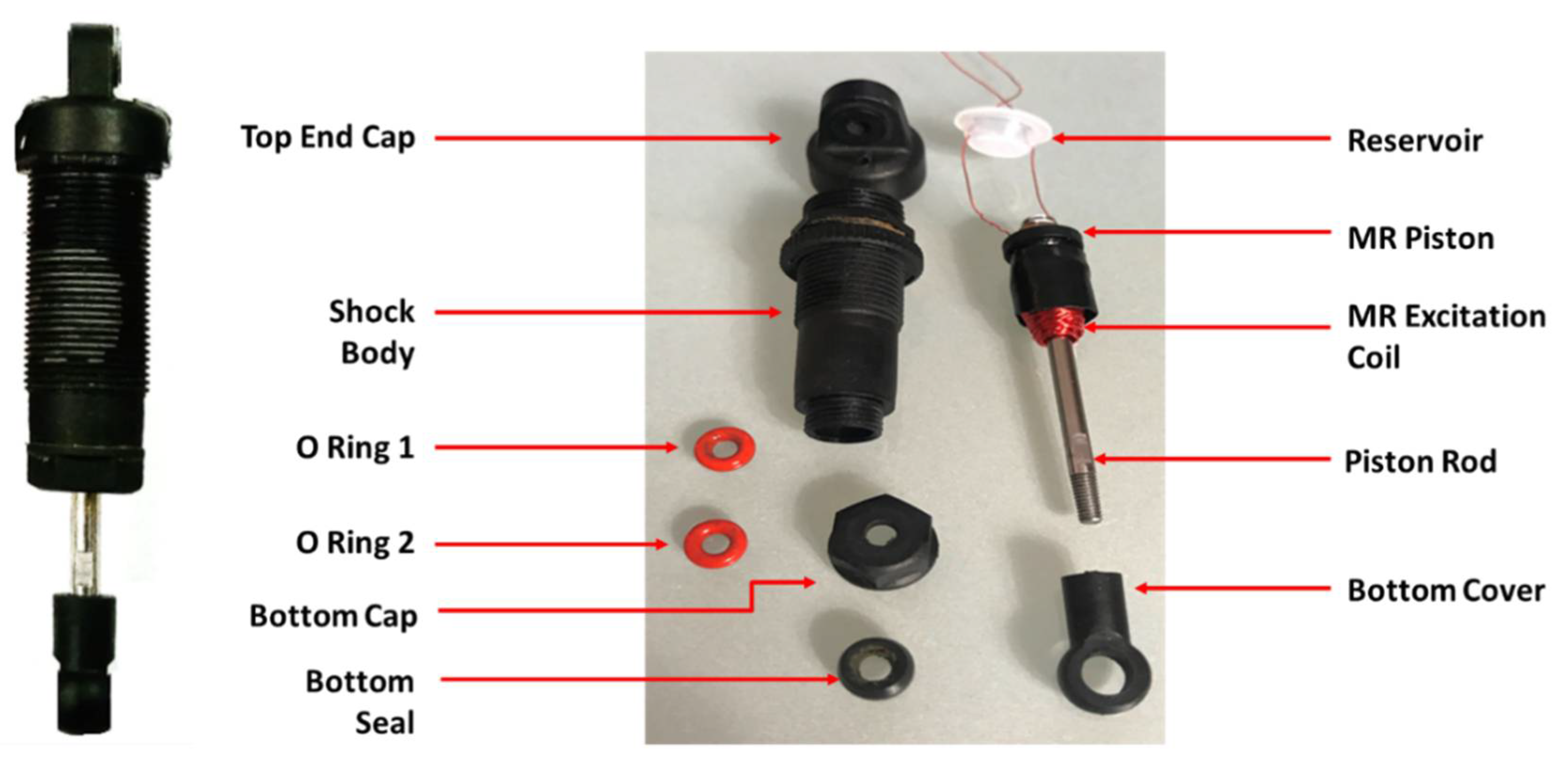
5. Fabrication of MR Damper

Figure 4 demonstrates the key components and assembly of the fabricated MR damper. The assembly contains a top end cap, shock body, o-rings, bottom cap, bottom seal, reservoir, MR piston, excitation coil, piston rod, and bottom cover. The materials of the MR damper are shown in Table 3. Table 4 shows the design parameters of the MR damper.
The MR fluid used in the damper is MRF-132DG from Lord Corporation (Cary, NC, USA). Lord MR Fluid-132DG is a hydrocarbon-based MR fluid, which contains micron-sized particles in a base fluid. When exposed to a magnetic field, the rheology of MRF-132DG fluid instantaneously changes from a free-flowing liquid to a semi-solid [22]. The properties of Lord MR Fluid-132DG are shown in Table 5. The typical magnetic properties of the Lord MRF-132DG Fluid, as provided by the manufacturer, are shown in Figure 5 [22]. Figure 6 shows the assembly of the proposed Energy-Harvesting Magnetorheological (EHMR) damper in a parallel configuration.

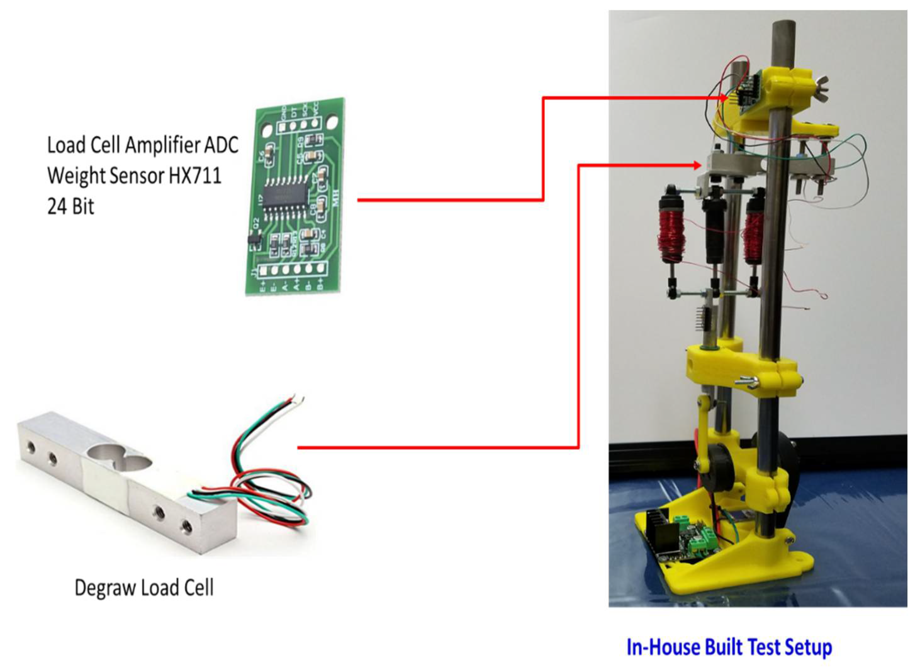
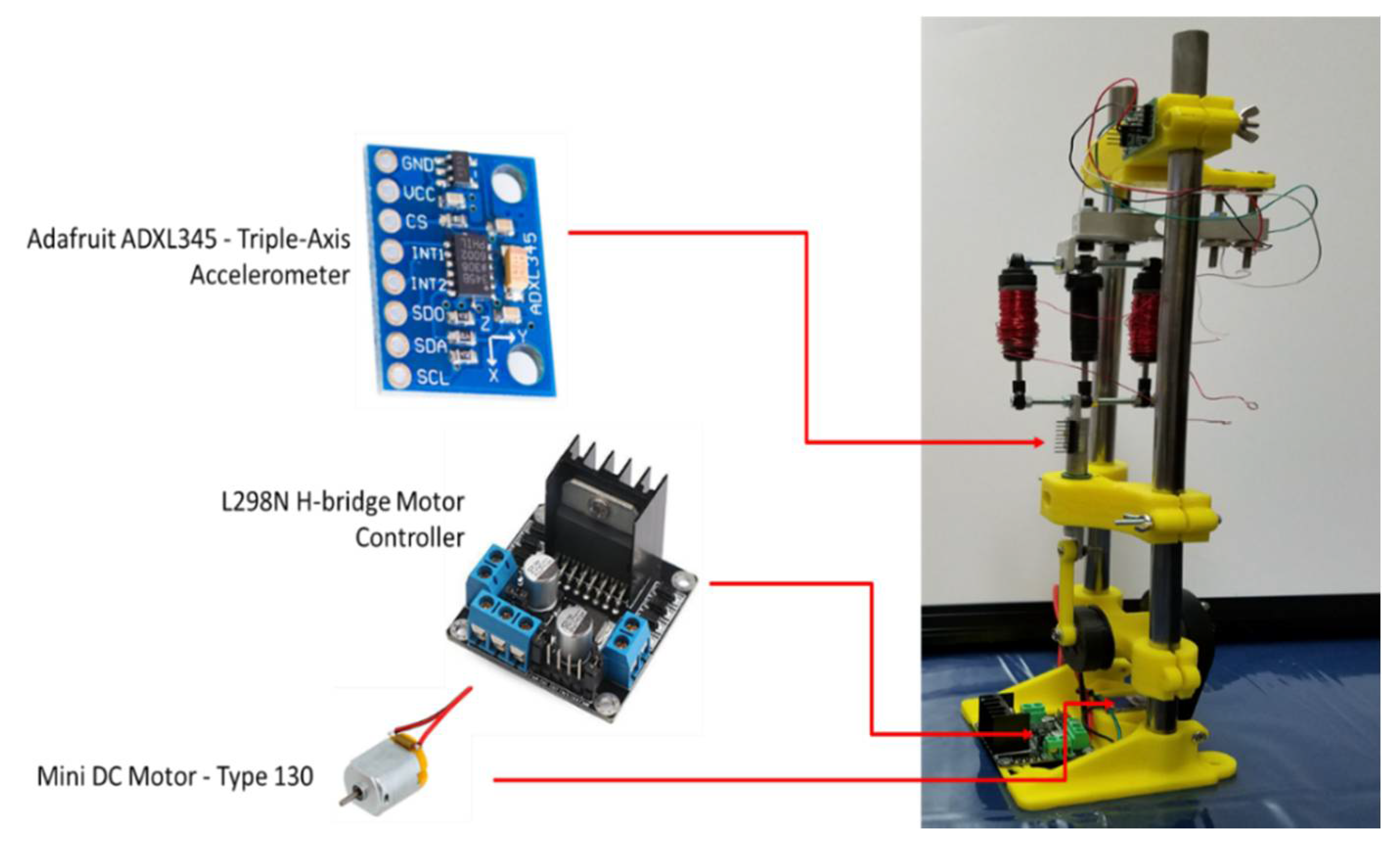
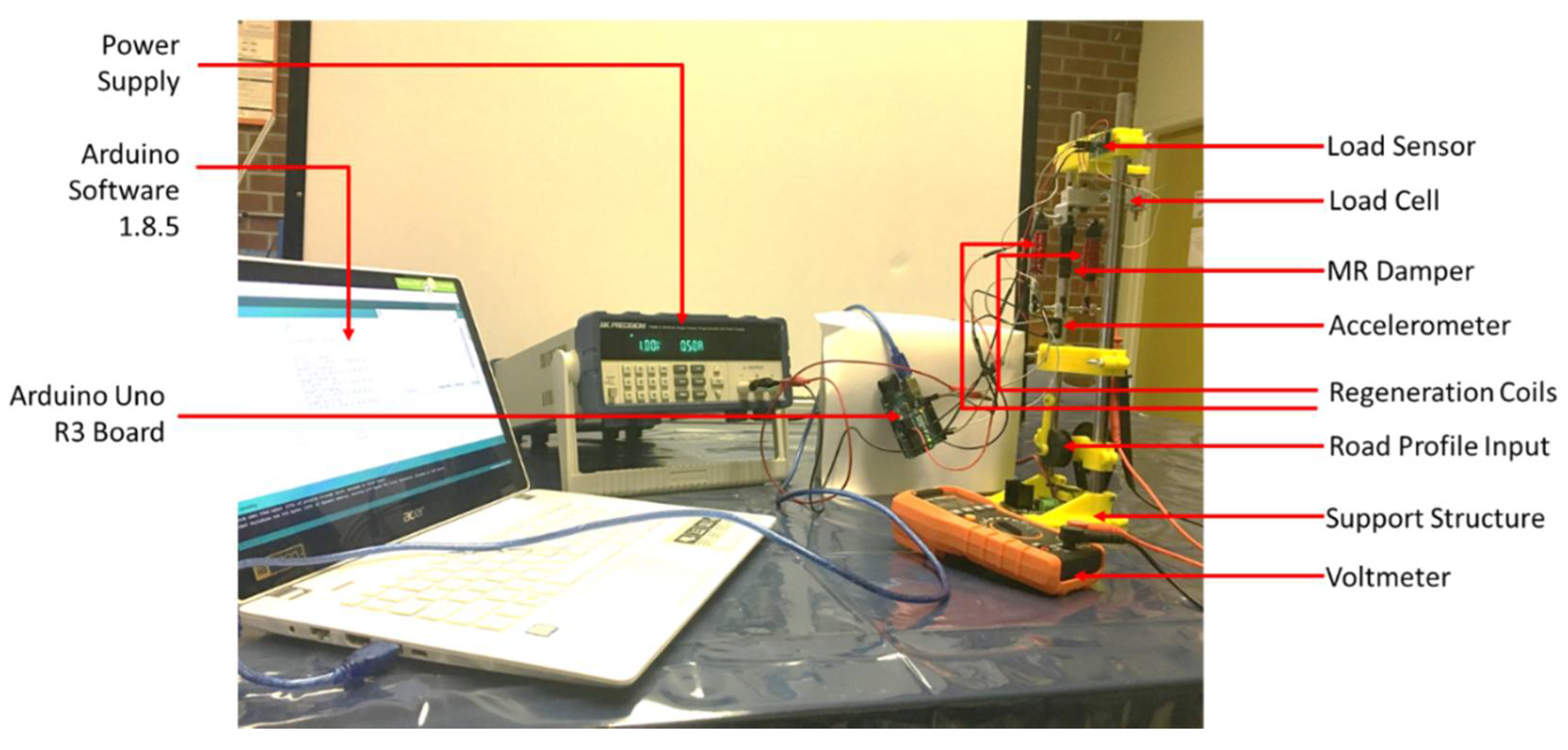
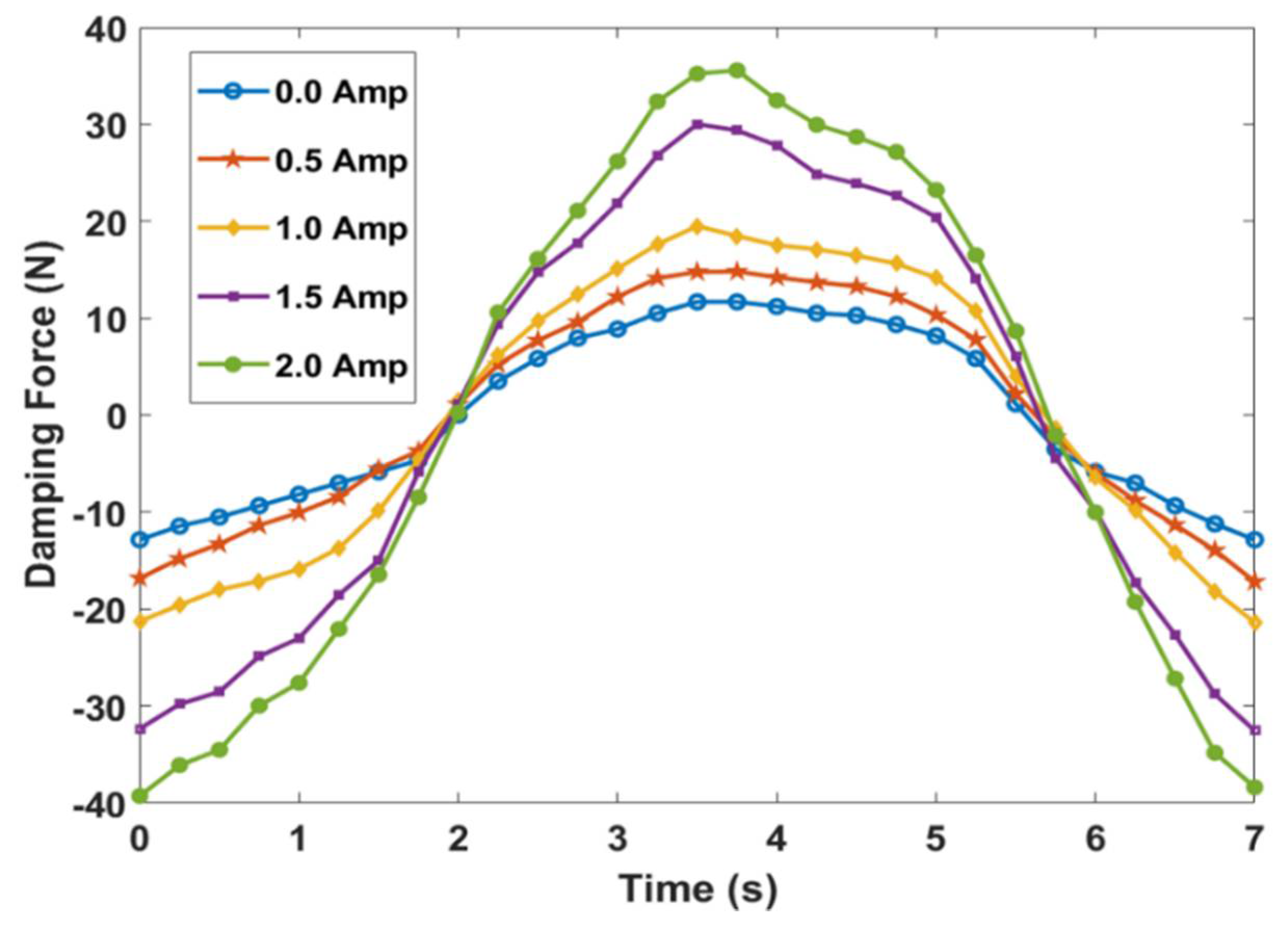
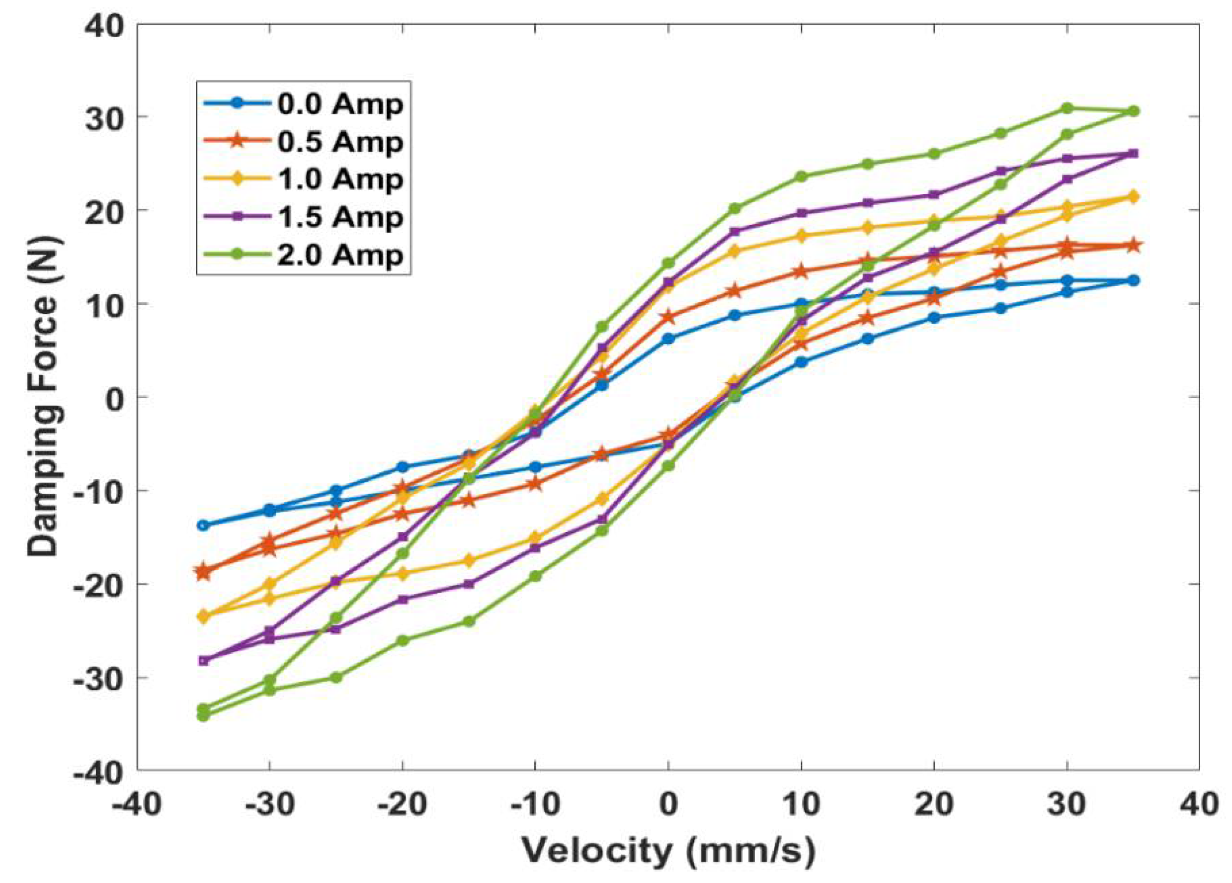
6. Testing of Proposed System

Figure 7 shows the load cell and load amplifier sensor used in the test setup. The load cell is made of aluminum alloy with the strain gauge pre-attached and strain-relieved wires. The range of the load cell is 0–5 kg. The dimensions of the load cell are 12.7 mm × 12.7 mm × 80 mm. There are four mounting holes, with 15 mm spacing on each side. On one side, both holes tapped M4 thread, on the other side both holes tapped M5 thread. The wire leads are 220 mm long.
The load cell measures the values of the damping force in an analytical form, which is further converted into the digital form by the HX711 load amplifier sensor. This top of the line load cell amplifier mounted on a breakout board pairs perfectly with the load cell to provide fast, accurate force measurements. It measures small changes in the resistance of the strain gauges mounted to the load cell and passes these values directly to an Arduino Uno microcontroller. The operating voltage range of HX711 is 2.7 V to 5.0 V. The operation current required is 1.5 mA.
An Adafruit digital ADXL345 is used as an accelerometer, as shown in Figure 8. The sensor has three axes of measurements, X, Y, and Z, and pins that can be used as digital interfacing. The sensitivity level needs to be given as ±2g, ±4g, ±8g, or ±16g. The lower range offers more resolution for slow movements; the higher range is suitable for high-speed tracking. The ADXL345 is the latest and greatest from Analog Devices, known for its exceptional quality micro-electro-mechanical system (MEMS) devices. The voltage common collector (VCC) takes in up to 5V and regulates it to 3.3V with an output pin.
A Qunqi L298N Motor Drive Controller Board Module Dual H Bridge DC Stepper (Qunqi, Guangzhou, China) is used for stepper control of the DC Motor. A Mini DC Motor-Type 130 is used to provide vibration inputs. The operative voltage for the motor is DC 1.5 V to 6.0 V. An Arduino Uno R3 Microcontroller A000066 is used to receive and deliver the data to and from the sensors. The microcontroller is connected to a computer with the use of USB 2.0 to supply the input voltage to the board itself. Arduino 1.8.5 software is used to collect the measured values of damping force and velocity. The full in-house built setup consists of a power supply for the MR damper, a computer with the Arduino software program, load cell, load sensor, accelerometer, stepper controller, DC motor, voltmeter, and the assembly of the energy-harvesting magnetorheological damper in the parallel configuration, as shown in Figure 9.

7. Results

Figure 10 represents the comparison between the damping force at 0, 0.5, 1.0, 1.5, and 2.0 Amp current excitation with respect to time (s). The figure shows that the values of the damping force vary under various operating current ranges.
The damping force vs. velocity diagram decides the working ability of a damper. The force vs. velocity diagram shown in Figure 11 represents the damping coefficient value. Ideally, this graph should be on a linear slope. However, no system in the world is ideal or perfect. Therefore, any force vs. velocity diagram of the actual damper does not have a linear straight line curve. In the compression stroke, the velocity of the damper increases, which also causes an increment in the damping force. Meanwhile, during rebound, the stroke velocity and damping force decreases. The curve of the compression and rebound stroke does not follow the same path, and a loop is created. This loop is called a hysteresis loop. It can be seen from the graph that under various input currents, the loop curve changes. These data show that with the increase in current, the damping force increased as the fluid thickened. The highest force observed was 31 N for 2 A current.
Figure 12 shows the calculated (theoretical) and measured (experimental) values of the induced voltage with respect to time. The amount of harvested energy is almost around that of the generated energy. The percentage of error is very low. The major reason for this error could be friction in the elements of the design and test setups.

8. Conclusions

In this study, an energy-harvesting magnetorheological damper system, in parallel configuration for application in lightweight battery-operated automobiles, is designed, fabricated, and tested. An analytical model is developed to predict the induced voltage through an energy-harvesting module, and a further parametric study is conducted through experimentation to understand the system performance. Furthermore, the analytical model is validated through experimentation. The major conclusions of the study are as below:
  • In this study, an EHMR suspension system consisting of an MR damper and an energy-harvesting module in the parallel configuration is successfully designed and fabricated.
  • The parametric study suggested that the parallel configuration of the energy-harvesting module with an MRD does not adversely affect the MR system performance.
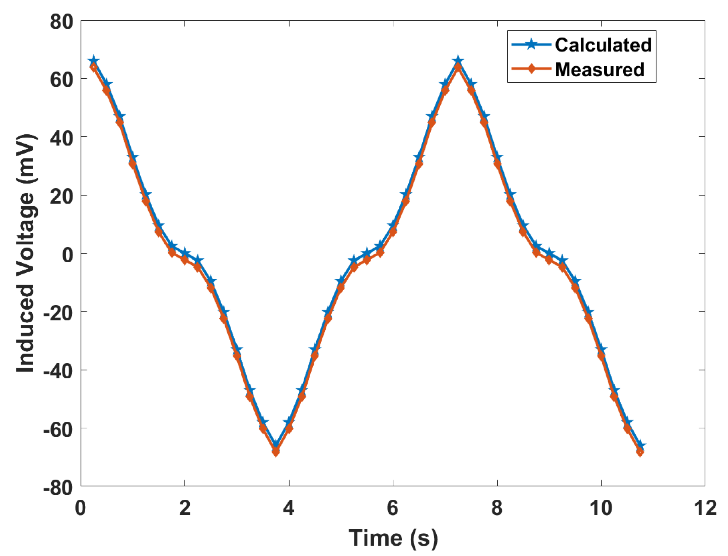
  • The analytical model is validated, and the model can predict the induced voltage from the energy-harvesting module within an accuracy of 3.5% error.
  • The energy-harvesting capability of the proposed system can be further improved by providing additional sets of magnets and increased coil windings.

Author Contributions

S.J. and U.K. conceived the idea and designed the experiments. U.K. performed the experiments, and S.J. interpreted and analyzed the experimental data. U.K. developed the mathematical model, and S.J. validated the model through experimentation. Both U.K. and S.J. prepared the manuscript together. All authors have read and agreed to the published version of the manuscript.

Funding

This research received no external funding.

Acknowledgments

The study acknowledges the financial support provided by the College of Engineering and Computer Science at California State University Fullerton.

Conflicts of Interest

The authors declare no conflict of interest.

References

  1. Zapateiro, M.; Pozo, F.; Karimi, H.R.; Luo, N. Semiactive control methodologies for suspension control with magnetorheological dampers. IEEE-ASME T. Mech. 2012, 17, 370–380. [Google Scholar] [CrossRef] [Green Version]
  2. Asadi, E.; Ribeiro, R.; Khamesee, M.B.; Khajepour, A. Analysis, Prototyping, and Experimental Characterization of an Adaptive Hybrid Electromagnetic Damper for Automotive Suspension Systems. IEEE T. Veh. Technol. 2017, 66, 3703–3713. [Google Scholar] [CrossRef]
  3. Taghirad, H.D.; Esmailzadeh, E. Automobile passenger comfort assured through LQG/LQR active suspension. J. Vib. Control 1998, 4, 603–618. [Google Scholar] [CrossRef]
  4. Ebrahimi, B.; Khamesee, M.B.; Golnaraghi, M.F. Feasibility study of an electromagnetic shock absorber with position sensing capability. In Proceedings of the 34th Annual Conference of IEEE Industrial Electronics (IECON 2008), Orlando, FL, USA, 10–13 November 2008; pp. 2988–2991. [Google Scholar]
  5. Qazi, A.J.; de Silva, C.W.; Khan, A.; Khan, M.T. Performance analysis of a semiactive suspension system with particle swarm optimization and fuzzy logic control. Sci. World J. 2014, 2014, 174102. [Google Scholar] [CrossRef] [PubMed]
  6. Symans, M.D.; Constantinou, M.C. Semi-active control systems for seismic protection of structures: A state-of-the-art review. Eng. Struct. 1999, 21, 469–487. [Google Scholar] [CrossRef]
  7. Chen, C.; Liao, W.-H. A self-sensing magnetorheological damper with power generation. Smart Mater. Struct. 2012, 21, 025014. [Google Scholar] [CrossRef]
  8. Çeşmeci, Ş.; Engin, T. Modeling and testing of a field-controllable magnetorheological fluid damper. Int. J. Mech. Sci. 2010, 52, 1036–1046. [Google Scholar] [CrossRef]
  9. Shen, Y.; Golnaraghi, M.; Heppler, G. Analytical and experimental study of the response of a suspension system with a magnetorheological damper. J. Intel. Mat. Syst. Str. 2005, 16, 135–147. [Google Scholar] [CrossRef]
  10. Bucinskas, V.; Mitrouchev, P.; Sutinys, E.; Sesok, N.; Iljin, I.; Morkvenaite-Vilkonciene, I. Evaluation of comfort level and harvested energy in the vehicle using controlled damping. Energies 2017, 10, 1742. [Google Scholar] [CrossRef] [Green Version]
  11. Sarbaev, V.; Garmash, Y.V.; Blinnikova, L. Recuperative shock absorber. Russ. Eng. Res. 2016, 36, 920–922. [Google Scholar] [CrossRef]
  12. Sapiński, B. Energy-harvesting linear MR damper: Prototyping and testing. Smart Mater. Struct. 2014, 23, 035021. [Google Scholar] [CrossRef]
  13. Hadjiloucas, S.; Walker, G.C.; Bowen, J.W.; Karatzas, L. Performance limitations of piezoelectric and force feedback electrostatic transducers in different applications. J. Phys.-Conf. Ser. 2009, 178, 012036. [Google Scholar] [CrossRef]
  14. Wang, Z.; Chen, Z.; Spencer, B.F. Self-powered and sensing control system based on MR damper: Presentation and application. In Proceedings of the Sensors and Smart Structures Technologies for Civil, Mechanical, and Aerospace Systems 2009, San Diego, CA, USA, 8–12 March 2009; p. 729240. [Google Scholar]
  15. Eriksson, J.; Piroti, S. Review of Methods for Energy Harvesting from a Vehicle Suspension System; KTH Royal Institute of Technology: Stockholm, Sweden, 2016. [Google Scholar]
  16. Hu, G.; Lu, Y.; Sun, S.; Li, W. Performance analysis of a magnetorheological damper with energy harvesting ability. Shock Vib. 2016, 2016, 2959763. [Google Scholar] [CrossRef] [Green Version]
  17. Ahamed, R.; Rashid, M.; Ferdaus, M.; Yusuf, H.B. Modelling and performance evaluation of energy harvesting linear magnetorheological (MR) damper. J. Low Freq. Noise Vib. Active Control 2017, 36, 177–192. [Google Scholar] [CrossRef] [Green Version]
  18. Cho, S.-W.; Jung, H.-J.; Lee, I.-W. Smart passive system based on magnetorheological damper. Smart Mater. Struct. 2005, 14, 707. [Google Scholar] [CrossRef]
  19. Choi, Y.-T.; Wereley, N.M. Self-powered magnetorheological dampers. J. Vib. Acoust. 2009, 131, 044501. [Google Scholar] [CrossRef]
  20. Sapiński, B. Vibration power generator for a linear MR damper. Smart Mater. Struct. 2010, 19, 105012. [Google Scholar] [CrossRef]
  21. Ghosh, A. Scaling laws. In Mechanics Over Micro and Nano Scales; Springer: New York, USA, 2011; pp. 61–94. [Google Scholar]
  22. Lord MRF-132DG Magneto-Rheological Fluid. Available online: http://www.lordmrstore.com/lord-mr-products/mrf-132dg-magneto-rheological-fluid (accessed on 14 May 2020).
Figure 1. MATLAB/Simulink model for energy harvesting.
Vibration 03 00013 g001
Figure 2. (a) Schematic of proposed energy-harvesting module. (b) Schematic of proposed Magnetorheological (MR) damper.
Vibration 03 00013 g002
Figure 3. Prototype design of proposed Energy-Harvesting Magnetorheological (EHMR) damper.
Vibration 03 00013 g003
Figure 4. Components and assembly of proposed MR damper.
Vibration 03 00013 g004
Figure 5. Magnetic flux density vs. magnetic field strength.
Vibration 03 00013 g005
Figure 6. Assembly of fabricated energy-harvesting MR damper.
Vibration 03 00013 g006
Figure 7. Load cell and load amplifier sensor in the test setup.
Vibration 03 00013 g007
Figure 8. Accelerometer, motor controller, and DC motor used in the test setup.
Vibration 03 00013 g008
Figure 9. In-house built energy-harvesting MR damper test setup.
Vibration 03 00013 g009
Figure 10. Damping force (N) vs. time (s).
Vibration 03 00013 g010
Figure 11. Damping force (N) vs. velocity (mm/s).
Vibration 03 00013 g011
Figure 12. Induced voltage (mV) vs. time (s).
Vibration 03 00013 g012
Table 1. Terms used in magnetic flux and induced voltage equations.
TermSymbol
Magnetic flux of air gap without considering the leakage ϕ g
Flux density of the magnet B r e m  
Magnet thickness τ m
Relative magnetic permeability μ 0
Magnetic field intensity of the magnet H c
Length of the air gap between piston rod and permanent magnet array g
Surface area of cylindrical air gap   A g
Cross-sectional area of the magnet   A m
Diameter of the shaft s
Table 2. Energy harvesting—design specifications.
Energy-Harvesting CoilInsulated Copper24 American Wire Gauge (AWG)
Magnet materialNeodymiumN48
Thickness of magnet25.4mm
Width of magnet12.7mm
Generation coil winding (number of turns)72
Generation coil winding resistance0.572 Ω
Relative magnetic permeability 4 π × 10 e 7 N A 2
Length of the air gap2mm
Diameter of the shaft3mm
Spacer thickness1mm
Table 3. Materials for MR components.
ComponentMaterial
MR PistonNylon
MR Excitation CoilInsulated Copper (32AWG)
Shock BodyAcrylonitrile Butadiene Styrene (ABS)
Piston RodSteel 1020
Bottom SealRubber
MRF FluidLord 132 DG
Table 4. Design parameters of MR damper.
ParameterValueUnit
Diameter of the piston10mm
Length of the piston2mm
Inside diameter of the cylinder12mm
Outside diameter of the cylinder15mm
Diameter of piston rod3mm
Length of damper in extended position78.75mm
Length of damper in compressed position70mm
Stroke length8.75mm
MR coil winding (number of turns)970-
MR coil winding resistance5 Ω
Table 5. Properties of Lord MRF-132DG [22].
Appearance Dark Grey
Viscosity @ 40   ° C   ( 104   ° F ) 0.112 ± 0.02
Density, g / cm 3   ( lb / gal ) 2.95–3.15 (24.6–26.3)
Solid content by weight, %80.98
Flash point, ° C ( ° F )>150 (>302)
Operating temperature, ° C ( ° F )−40 to +130 (−40 to +266)

