
Earthquake-Resilient Design of Seismically Isolated Buildings: A Review of Technology

Faculty of Engineering and Natural Sciences, Bahcesehir University, Istanbul 34349, Turkey
Vibration 2021, 4(3), 602-647; https://0-doi-org.brum.beds.ac.uk/10.3390/vibration4030035
Submission received: 16 May 2021
/
Revised: 2 July 2021
/
Accepted: 14 July 2021
/
Published: 22 July 2021
(This article belongs to the Special Issue Progressive Collapse of Buildings)
Abstract
:Earthquake Seismic isolation plays an important role in achieving sustainable earthquake resilience communities. Seismic isolation method is a justified, mature, and reliable performance enhancement strategy for a wide range of structural systems and valuable contents. As a result of the targeted response modification, high-performance expectations and earthquake resilience can be achieved during the service life of the structures that are compliant with the design code requirements. Design and analysis procedures of isolation systems in standards were evolved substantially to expand the use of isolation technology and quantify the benefits of isolation systems to overcome the existing impediments. Strictly speaking, new tools are offered to the engineering community to highlight the possible issues that may appear in isolation units beyond the design basis earthquake level to improve the accuracy of response prediction. This paper aims to overview the characteristics of frequently used isolation systems in the industry with mathematical models, design criteria toward sustainable communities, the current state of practice along with the set forth design requirements of selectively well-known standards with special emphasis to the ELF procedure from the perspective of performance-based design philosophy. Additionally, two large-scale seismic isolation applications in the world are given as benchmark studies for the new construction and upgrading scheme in the content of the study.
1. Resilience and Robustness of Seismically Isolated Buildings
Earthquake is a natural threat to human lives and assets, and a high portion of the world’s population lives in earthquake-prone regions [1]. Past major earthquakes indicated the vulnerability of building stocks and infrastructures in urban areas (e.g., the 1994 Northridge earthquake, the 1999 Kocaeli and Duzce earthquakes, the 2011 Christchurch earthquake, the 2011 Tohoku-Oki earthquake, and the 2016 Kumamoto earthquake). Seismic design codes have been instrumental in reducing collapses of non-isolated structures and have saved the lives of hundreds of thousands of people. However, over the past 20 years, especially in developed countries, nonstructural system/component damage and loss of functionality (and consequent loss of business) dominated the economic losses caused by earthquakes [2,3,4,5]. Strictly speaking, in the 1994 Northridge earthquake, financial losses due to nonstructural damage were approximately constituted 50% of the estimated total loss of 18.5 billion dollars [6].
Nowadays, modern buildings contain sensitive and costly equipment, that has become vital in business, commerce, education, and healthcare. These building contents frequently are more valuable than the buildings themselves. According to Taghavi and Miranda [5], financial losses associated with the physical nonstructural damage can rise to 70% of the entire cost where the structural system only constitutes 18% of the investment. Thus, the likelihood of losses under a similar scenario earthquake like the 1994 Northridge earthquake might exceed the previous estimates of total losses because of the costly new technological equipment, architectural components, and building contents, and business interruption. Since the primary objective of seismic risk mitigation activities is to reduce the adverse effects of earthquakes such as casualties, loss of functionality, downtime, and direct or indirect economic losses: earthquake-resistant design of new structures and rehabilitation of existing ones with appropriate performance criteria, should constitute a priority.
This paper overviews the fundamental principles of seismic isolation technology, impediments in extending the use of isolation systems, the current state of practice for the design and analysis of most commonly used isolation hardware with a critical appraisal of the justified performance of SI buildings in the past earthquakes. Moreover, a direct displacement-based design approach in a seismically isolated building along with the set forth design requirements of selectively well-known standards are addressed from a PBD aspect. Finally, the paper ends with the author’s remarks on the issues in the design of isolated structures and the presentation of benchmark studies for the continued functionality objective of healthcare facilities in Turkey.
2. Fundamental Principles in the Design and Analysis of Seismic Isolation Systems
Seismic isolation is an effective design and rehabilitation methodology to ensure the desired high-performance expectations in a wide range of applications. The first patented earthquake protection system in the US goes back to the end of the 19th century [7], while the historical background of the conceptual idea is far beyond that era. Although from the 1970s to 2000s seismic isolation technology was proposed as an innovative performance enhancement strategy, nowadays it is transformed to mature and arguably the best way of earthquake protection method [8]. The design concept of passive control systems relies on the decoupling of the entire structure or floor levels through the installation of isolation devices at key interfaces, which enables the shifting of the fundamental vibration period of the structure out of the hazardous range of earthquakes that have the highest level of energy content. In other words, the low-horizontal stiffness provides accommodation of deformation demands at the isolation interface, and the inherent/supplemental damping mechanism avoids the excessive deformation that might be detrimental (Figure 1).
Accordingly, the SI system introduces flexibility to the designer for the installation of isolation units at the foundation, first floor [11], or any other convenient floor level in a building to directly account for the dissipation of earthquake-induced energy with feasible solutions (Figure 2). As a result of the adapted mechanism, anticipated floor accelerations and interstory drifts in the superstructure can reduce drastically. In contrast, fixed-base structures concentrate the inelastic deformations in specified locations of structural members for fulfilling the code-compliant collapse prevention criteria and it may result in very high floor accelerations in stiff buildings or large interstory drifts in the flexible structures, causing difficulties in ensuring the safety of the non-structural components and contents.
Despite tons of scientific papers published in the literature and evolution of designed codes, engineers in the industry still stand distant from isolation technology due to a lack of understanding of the primary benefits of used approaches in isolated structures. Moreover, impediments addressed by Mayes et al. [12] in the 1990s still exist and restrict the use of passive control systems. Therefore, the authors would like to reemphasize some of the noteworthy benefits of appropriately applied technology as follows:
- (a)
- As a result of reduction of elastic base shear force determined based on the site conditions and seismicity requires less effort with a simpler configuration and limited ductility in the superstructure;
- (b)
- Ground motion records that may yield extensive damage for an isolated structure can be determined through a comprehensive seismic hazard assessment in the preliminary design phase;
- (c)
- Sensitivity of SI structures to uncertainties associated with earthquake hazard result in less than the conventional structures;
- (d)
- The amount of damage sustained in the superstructure is kept in minor levels even under the rare earthquake ground motion levels with feasible design solutions;
- (e)
- The performance of isolation devices is known better than the structural members of its fixed-base counterparts due to provided quality assurance tests and validated mechanical characteristics in prototype tests;
- (f)
- Nonlinearity of seismically isolated structures is concentrated in the isolation interface even beyond the considered level of earthquake ground motions due to conservative safety margins and modification factors considered in the bounding analysis;
- (g)
- Continued functionality can be easily provided by upgrading the existing systems based on the performance expectations of stakeholders or updates in design provisions.
Thus, seismic isolation technology is an alternative robust design and rehabilitation method that fulfills the code requirements while contributing to the community resilience for regions under earthquake threat. Despite burdensome requirements in standards that are not applied to traditional structures fairly, seismic isolation systems still have promising features to provide cost-effective options for performance enhancement and long-term safety regardless of those limitations. Increasing attention of the construction industry to innovative technologies has made the seismic isolation systems arguably the first applicable solution to overcome the challenging problems for performance enhancement. As a consequence of research and development activities in isolation and energy dissipation systems, the total number of available devices in the market and local suppliers are increased considerably in the past three decades. Elastomeric bearings and friction type of sliders are still the predominantly employed types of isolation units in practice due to their ease of applicability and approved performance in earthquakes. The procedure for selecting the most suitable seismic isolation system is not straightforward and differs from traditional building practice. Thereby, performance evaluation of SI systems and optimum design need to be evaluated project-wise and in a device-specific manner. A thorough understanding of mechanical characteristics and design parameters of devices together with the superstructure characteristics is a must in the decision process, where good communication with suppliers is key. Basic response characteristics of commonly used isolation units belonging to the elastomeric and friction slider categories of isolation units are described briefly in this section.
2.1. Elastomeric Bearings
Elastomeric bearing devices are commonly used in many applications starting from the rudimentary years to date. Various types of elastomeric bearings were manufactured in the 1980s for bridges and buildings to promote cutting-edge technology for structures. The first modern building equipped with a seismic isolation system consisting of a rubber-bearing was constructed more than 50 years ago in Skopje. Bulging observed in devices was caused by inadequate vertical stiffness of rubber due to a lack of reinforcing shims [8,13]. Thus, rubber bearings installed in 1969 at Pestalozzi School are replaced 40 years later with their contemporary versions that can exhibit adequate vertical stiffness and desired dynamic response characteristics.
Overall response characteristics of the elastomeric bearings are represented by mathematical models in the design and analysis of seismically isolated structures. Therefore, a set of parameters such as effective stiffness (Keff), equivalent viscous damping (eff), characteristic strength (Qd), and post-yield stiffness (Kd) parameters are needed to be validated through the required test procedures or preliminary analysis are performed by obtained parameters from verified devices subjected to approximately similar loading conditions. The first two parameters given are used in linear analysis, and the Qd and Kd can be used to establish the idealized bilinear hysteretic model for the nonlinear response history analysis. An idealized bilinear force–displacement relationship of an isolation system is shown in Figure 3. In addition, more advanced hysteretic models can be used to address the issues that might appear in rare seismic events.
Elastomeric isolation units can be classified into three main categories based on their damping properties and material comprised. In European Standard EN 15129 [14], a device named polymer-plug rubber bearings (PPRB) is included together with three main elastomeric bearings. Type of elastomeric bearings and their mathematical models used to represent the mechanical behavior of elastomeric bearings under dynamic loading are described briefly in this section.
2.1.1. Low-Damping Rubber Bearings (LDRB)
LDRB is composed of natural rubber, steel shims, and endplates (Figure 4). It shows a linear force-deformation behavior with low energy dissipation capacity (2–3%) up to 100% shear strain. It is possible to experience a stiffening behavior in the horizontal force–displacement relationship beyond the upper limit of shear strains. The shear strain of elastomeric bearings is calculated considering lateral load, compression, and rotation effects. Shear strain value at the onset of stiffening in LDRB differs from HDRB. Thus, the hardness of rubber material is a matter to reflect the possible range of shear modulus in elastomeric bearings. The hardness of rubber is measured by an instrument named the durometer. The shear modulus of LDRBs typically ranges from 0.65 to 1.0 MPa. For achieving a stable response in an isolation system consisting of LDRBs, usually hardware such as lead rubber bearing (LRB), high-damping-rubber-bearing (HDRB), viscous fluid dampers, frictional dampers, yielding hysteretic steel dampers, and lead bars among others are used together with this type of devices to limit excessive displacement demands.
The horizontal stiffness parameter (Kd) of the elastomeric bearing can be calculated using Equation (1). Shear modulus and bonded area of the elastomeric bearing are denoted by G and Ab, where the total rubber thickness of the bearing is represented by Tr. In Equation (1), reasonable percentage of rubber cover used for protection preferably can be included, too. Similarly, the vertical stiffness parameter (Kv) is calculated by Equation (2) considering the compression modulus of the rubber-steel composite, , and area of steel shim rather than the shear modulus of bonded rubber bearing. parameter in Equation (3) assumes the incompressibility of rubber for circular pads. In case of having a central hole in the elastomeric bearing value yields to a smaller value. In addition to the given parameters, shape factors are critical. Rubber-bridge bearing typically has lower first shape factor values (S1) compared to elastomeric isolation units. Higher shape factor values in elastomeric bearings contribute to enhancing the stability and limit the undesired rocking motion. When the shape factor value is high, the effect of compressibility must be taken into account to calculate the Kv value (Equation (4)) through bulk modulus, K. Since it is hard to measure bulk modulus in the laboratory environment, 2000 MPa value is assumed for the bulk modulus of the rubber. In Equation (4), denotes the longitudinal elasticity modulus, and the αv and κ correction factors are used for the and rubber hardness, respectively.
2.1.2. High-Damping-Rubber-Bearing (HDRB)
High-damping and low-damping rubber bearing have a similar configuration as shown in Figure 4. However, the rubber compound used with fillers differs and provides a moderate level of inherent damping capacity to HDRBs. Damping ratios of HDRB can reach up to 10–20% for 100% shear strain based on the manufacturer’s propriety [8]. The shear modulus of high-damping rubber bearing usually ranges between 0.35 MPa and 1.4 MPa. Thus, HDRB effective stiffness may vary based on fillers used in the compound, vulcanization process, and contact pressure related to the bonded rubber area. In case of considering the stiffening response at high shear strain values, simplified bilinear models are not applicable like in the lead rubber bearing or conventional curved surface friction slider. Thereby, a phenomenological model was proposed to draw attention to the variation of response characteristics beyond the design basis earthquake by Grant et al. [15]. The proposed model elaborates Mooney-Rivlin strain energy function defined by a comparable approach corresponding to surface plasticity. It represents the range of stiffness and damping for different shear strain values. Alternatively, a uniaxial mathematical model is developed by Kikuchi and Aiken [16] to capture the variation of response characteristics in good agreement with the experimental data utilizing the multi-spring approach (Figure 5).
Furthermore, the velocity of loading, strain and load history, and ambient temperature affect the force-deformation characteristics of high damping rubber bearings during the cyclic tests. Numerous experiments have also exhibited scragging and the Mullin effect on HDRB bearings caused by bulk modulus reduction at moderate to large shear strains [17,18]. The softening ratio in the first cycle to an assigned shear strain is higher than the subsequent cycles. This phenomenon is first described by Mullin [18]. Then, Clark distinguished the impact of softening by explaining the permanent softening as scragging and the temporary reduction as the Mullin effect. In AASHTO [19], de facto values of property modification factors are defined for HDRB, LRB, and LDRB based on aging and scragging.
2.2. Lead Rubber Bearing (LRB)
Lead-rubber bearing is first introduced in New Zealand by Robinson in the late 1970s, where seismic isolation applications using LRB are utilized all over the world [20,21,22]. As a common practice, the fabrication process of LRB is identical to a low-damping rubber bearing except for the inserted lead plug to the center hole. Lead core yields at a relatively low level of stresses at normal temperatures, and it has a recrystallization property providing a stable dynamic behavior under repeated cycles. In other words, the elastomer provides low horizontal stiffness, and the lead core provides characteristic strength and the energy dissipation feature for avoiding excessive deformations. Internal construction from a cut-away view and typical uniaxial cyclic response of multi-spring analytical models are given in Figure 6.
Rate-independent bilinear models are used to represent the force–deformation relationship of lead rubber bearings in object-oriented and commercial software. In practice-oriented applications, the idealized hysteresis loop is governed by three parameters, namely characteristic strength (Qd), post-elastic stiffness (Kd), and yield displacement (Dy). Characteristic strength can be calculated by using only the properties of the lead plug (Equation (5)). Yield strength and cross-sectional area of the lead core in Equation (5) are denoted by and , respectively.
Rate-independent plasticity models are commonly used in object-oriented and commercial software. Bilinear force–deformation relationship of LRBs can also be represented by employing Bouc-Wen [23] and coupled-plasticity with a circular yield surface (Figure 7). In this way, force–deformation relationships can be captured with acceptable accuracy. Bouc-Wen model incorporates the smooth plasticity models that are compatible with the test data. However, analysis results may lead to the underestimation of displacement demands by omitting the coupled plasticity models.
In structural analysis programs like SAP2000 [24], 3D-BASIS-ME-MB [25] two-directional smooth bilinear hysteretic models are established utilizing the approach of Park et al. [26]. Smooth bilinear hysteretic models give acceptable results under bi-directional input motions [25]. The forces mobilized in the orthogonal directions during earthquake excitation can be defined by Equations (6) and (7). The isotropic formulation is an appropriate idealization to describe the bi-directional behavior of lead rubber bearings.
α is the post-yield stiffness ratio, is the yield force, and Y is the yield displacement. Zx and Zy are two dimensionless variables governed by the following differential equations proposed by Park [26]. A, γ, and β are dimensionless parameters that control the shape of the hysteresis loops. The proposed model can be utilized for all types of elastomeric bearings. High-damping-rubber-bearing requires special attention due to shear strain-dependent stiffening behavior.
2.3. Friction Slider Type of Isolation Systems
Friction reduction and lubrication are well-documented to emphasize the economic aspects, reliable performance, and longevity in different disciplines. Increasing earthquake demand parameters were necessitated to develop new passive control hardware with higher displacement capacity. The first contemporary application of the sliding isolation system had a flat surface with a low coefficient friction parameter in the patented design approach of Johannes Avetican Calantarients in 1909 [8]. The main difference between these two approaches was the incorporation of a low friction coefficient with more controllable self-lubricating materials and stainless steel rather than creating a layer of Talc. Numerous self-lubricating materials have been proposed to provide a low coefficient of friction in sliding isolation hardware.
Polytetrafluoroethylene (PTFE) is the most commonly used self-lubricating material among the available ones in flat and curved surface friction sliders. In addition to PTFE, known as Teflon, Polyethylene, and Polyamide-based materials have started to be used as an alternative material to reduce friction in Europe. In this way, favorable features of polymers are adapted to be functional under a high level of contact pressure and temperature. The PE-based self-lubricating material in Europe is named UHMWPE (ultra-high-molecular-weight-polyethylene), where the high strength property is a result of its molecular chain. Using such various composite materials in contemporary sliding isolation systems dictates quantifying key design parameters and establishing approval criteria to be used in manufacturing. Thereby, certification of materials in isolation hardware is a must in Europe. Quaglini et al. [27] have proposed a small-scale test procedure for self-lubricating materials to reproduce the actual condition of sliding isolation units.
The design procedure of friction sliders relies on the fundamental concepts of structural mechanics, material properties, and consideration of tribology on macro scales. Several models that are available in the literature can be incorporated to compute the friction force. Coulomb friction is the simplest model to apply in dynamic analysis among others. However, it is well understood that friction force developed at the interface of two materials is dependent on the contact pressure, sliding velocity, ambient temperature, temperature rise on the sliding interface, load and deformation path history, the degree of wear, and cleanliness of the surface. In the light of characterization tests, the velocity-dependent friction model is found to be adequate in the design and employed in both practice-oriented and object-oriented software for practical purposes.
Mokha et al. [28] have conducted a series of tests on sheet-type Teflon sliding bearings under varying bearing pressures, and static and sliding kinetic coefficients of friction measurements are obtained to calibrate the friction model of the PTFE sliding bearings. Critical findings from this study were the dependencies of the frictional force on the velocity of sliding, on bearing pressure, and the condition of the interface. The dependency of the coefficient of friction to the sliding velocity and the variation of the contact pressure is represented by Equation (9) in mathematical models (Figure 8a). The maximum coefficient of friction and minimum coefficient of friction are denoted by fmax and fmin in Equation (9), where the rate parameter and velocity are represented by a , respectively.
Similarly, variation of fmax parameter based on the change of contact pressure can be represented using Equation (10) (Figure 8b). Moreover, it is possible to use more sophisticated models to demonstrate the strength degradation due to temperature rise on the sliding interface [29,30].
2.3.1. Conventional Curved Surface Friction Sliders
Curved surface friction slider (CSFS) bearing is a form of sliding bearing consisting of an articulated slider on a stainless-steel spherical surface. The first patented device in North America is named Friction Pendulum SystemTM (FPS) [32]. However, several patent applications in history indicate that the idea of friction sliders goes back to more than 100 years ago [7,33]. The drawings of a contemporary version of the friction slider in the patent application by Zayas et al. had some similarities with the patent of Penkhun [34].
Contemporary CSFS provides the sliding mechanism consisting of friction force and restoring capability in a single unit. The first modern application of CSFS type of bearings is used to retrofit an apartment building in California in 1989 [8]. Since then, traditional curved surface friction sliders have been used widely to isolate buildings, bridges, and storage tanks where design provisions for CSFS. Such widespread use of curved surface sliders has necessitated the implementation of the standardized design and analysis rules together with the required test protocols in standards. Design provisions for CSFS have been implemented to relevant standards to cover generic behavior with special emphasis on the restoring force capability rather than referring to a particular trademark friction slider [35,36].
The force–displacement behavior of CSFS is dependent on the coefficient of friction, variation of axial load on the bearing, and effective radius of curvature. Geometric configuration and the free body diagram of a curved surface friction slider are illustrated in Figure 9. Based on the small deformation theory, Equation (11) can be used in the preliminary design of the curved surface friction sliders to represent the rigid-plastic response. Tisol of the CSFS depends only on the effective radius of curvature value due to the nature of the isolation device, where the horizontal stiffness and equivalent hysteretic damping can be calculated considering Equations (12) and (13). But when the angular displacement amplitude of the pendulum becomes large enough that the small-angle approximation no longer holds, then the equation of motion must remain in its nonlinear form. Although small-deformation theory can capture the overall response of seismically isolated structures, the need of employing a more sophisticated analytical model that accounts for the P-Δ effects under large deformation demands was dictated in past earthquakes (e.g., the 1994 Northridge, the 1995 Kobe, the 1999 Kocaeli, the 2009 L’Aquila, the 2011 Christchurch, and the 2011 Tohoku earthquake). The nonlinear force-deformation response history of CSFS is decomposed to friction force and restoring force components in Figure 10.
Earthquake ground motions at a point consist of three translational and three rotational components. Unidirectional consideration might be misleading to evaluate the critical design parameters of sliding isolation units. Therefore, nonlinear response history analysis of seismically isolated bridges by accounting bidirectional loading and coupled plasticity models was performed by various researchers [37,38] to assess the accuracy of the uniform load pattern method in AASHTO Guide Specification. The importance of bi-directional loading and variation of the axial load for the rate-independent model of curved surface friction sliders are highlighted by Mosqueda et al. [39]. A simplified approach considers two independent unidirectional elements according to Coulomb’s friction model in orthogonal horizontal directions. Force-deformation calculation can be carried out using Equation (14), where N is the axial force acting on the isolator, is the effective radius of curvature, u and denote the sliding displacement and the sliding velocity, respectively. Friction forces for two directions are arranged as given in Equation (15). The commercial software [24] and 3D BASIS-ME [31] use a smoothed plasticity model for FP bearings that utilizes the bidirectional Park–Wen model [26]. In addition, Tsai et al. [40,41] proposed a finite element formulation to include local bending moments for unidirectional and bidirectional motion.
Furthermore, breakaway friction, stick-slip condition, and coupled bi-directional force–deformation relationships can be observed during the characterization tests of sliding isolation units. A conventional type of curved surface friction slider is incorporated to assess the possible seismic upgrading schemes in the RETRO project. The test protocol described by Lomiento et al. [29] is applied to determine the mechanical features of the traditional CSFS unit. For the pseudo-dynamic testing of a large-scale bridge structure in JRC-ELSA laboratories, the influence of breakaway friction and stick-slip conditions are illustrated in Figure 11 [42]. A constant vertical load of 450 kN per isolator is applied to isolators at the short and tall piers, in which runs of five sine cycles at a constant frequency of 1/100 Hz were imposed with amplitudes of 50, 40, 30, 20, and 10 mm. The maximum velocity at every amplitude ranged from 3.14 to 0.63 mm/s.
More advanced analytical models of traditional curved surface friction sliders to demonstrate the importance of multi-directional loading and the influence of heating are given in a section devoted to challenges in the design.
2.3.2. Multi-Surface Friction Sliders
Following the conventional curved surface friction slider, multi-surface friction sliders consisting of two and four sliding surfaces are introduced to the earthquake engineering community for having a more compact and economical device with a higher margin of safety (Figure 12). The conceptual idea of a multi-surface isolation system goes back to the original patent of Jules Touaillon’s double concave rolling ball mechanism in 1870 [7]. Its contemporary version incorporates advanced self-lubricating wear material and a stainless-steel sliding surface with a more stable response feature. The displacement capacity limitation increasing the cost of conventional curved surface friction sliders is overcome with a performance enhancement through an adaptive response of multi-surface curved friction (MSCF) sliders. The adaptive MSCF type of isolation unit can exhibit varying strength and stiffness characteristics with increasing amplitude (Figure 13). In addition to cost benefits, sharing the displacement demands among multiple surfaces for the special configuration result in halving of the sliding velocities, reduction of deterioration in wear material, and variability of friction force along with compatibility to multi-level performance objectives.
A conventional curved surface friction slider is transformed to a multiple independent pendula mechanism to achieve an adaptable behavior while creating cost-effectiveness. Multiple pendulum mechanism in a single isolation unit is investigated through analytical and experimental studies by Tsai [46,47,48,49]. Following the initiative works of Tsai et al., comprehensive characterization tests of MSFS with two sliding interfaces with different configurations and dimensions are carried to confirm the accuracy of earthquake demand predictions from developed theory in the study of Fenz and Constantinou [43] and Morgan and Mahin [50]. Mathematical models of double and triple pendulum motion of MSCF sliders are developed using either available nonlinear elements or a specific link element by several researchers [43,44,45,50,51,52]. Hysteresis loops of mathematical models for triple and double pendulum motion with sliding regimes are shown in Figure 13. Special configurations of multi-surface friction sliders have widespread use in practice, where appropriate geometry and coefficient of friction parameters at each sliding interface are assigned using equal radii and coefficient of friction based on the device type. Fenz and Constantinou [43,45] have proposed equivalent analytical models validating the observed response considering the available suite of nonlinear link elements in commercial software during the time of nonexistent particular link elements for multi-surface friction sliders. The proposed series model of the MSCF slider with triple pendula motion by Fenz and Constantinou is validated and verified under unidirectional motion. Series models can work under multi-directional motion using radial configuration but can be computationally expensive. Thus, the link element developed for MSFS in commercial computer programs can be preferred. Series and parallel models of the multi-surface curved friction sliders are given in Figure 14 [45,51].
Furthermore, the remarks of Tsai et al. [53,54] about more complex multi-surface friction sliders named Quintuple consisting of six sliding surfaces, nine regimes, and five pendula for complex multi-stage adaptive behavior are utilized by Lee and Constantinou for the extension of the MSCF slider with triple pendula motion by including the proper unloading portion of the hysteretic behavior [55]. Similar to the study of Fenz and Constantinou [49,53], modeling of the overall behavior of Quintuple devices in commercial software is provided similarly for the practicing engineers.
3. Performance of SI Structures in Major Earthquakes
3.1. Design Issues
Lessons learned from earthquakes highlighted some design issues of isolation systems in the state of practice. In the 1990s, the failure of seismic isolation systems and the poor performance of this technology are attributed to the improper applications, inconsistent displacement capacity estimates with the seismic hazard, and the lack of understanding behavior of devices under certain conditions. For instance, during the 1999 Duzce earthquake, the issue of insufficient displacement capacity of the isolation units led to the failure of all devices in Bolu Viaducts. Similarly, the overloading of piers and stiffening of seismic isolators in cold temperatures are associated with the undesired response of devices in the 1993 Kushiro-Oki earthquake [56].
Apart from SI applications in bridges, seven seismically isolated structures in the Los Angeles area were affected by 17 January 1994, M6.8 Northridge earthquake. Two buildings equipped with seismic isolation in the region could not fully be activated and did not respond as intended [57]. Similarly, according to Kuang et al. [58], in the 2011 Christchurch earthquake, the Christchurch Women’s Hospital (CWH) building responded very differently from the design perspective and targeted performance objective. Building design by following specifications is aimed to have a lower stiffness and yield strength value than what was observed in two relatively large events on 23 December 2011.
Another important design issue in SI structures is the failure of connection details. Kani et al., Kasai et al., and Morita have reported failure of connections details of the isolation units in the 2005 Fukuoka and 2016 Kumamoto earthquakes in Japan [59,60,61]. Reported design issues are handled by revised code provisions, design recommendations, and enhanced mechanical characteristics of isolation units in the manufacturing process.
3.2. Seismic Performance of Monitored Buildings
Structural health monitoring in seismically isolated (SI) are essential to fully understand the response characteristics of the protection system during earthquakes and gather valuable information about the level of performance enhancement and damage state. However, the number of monitored SI buildings is relatively low compared to the total number of IS structures. Several instrumented buildings were provided important information about the seismic performance of earthquake protection systems and highlighted the verification of performance goals and design issues in major earthquakes.
During the 17 January 1994 Northridge earthquake, the first set of strong-motion records are retrieved from a base-isolated hospital building of the University of California (USC). PGA values are found larger than the results of the postulated design criteria and the isolation system experienced nonlinear displacements that led to a reduction of floor accelerations at floor levels [62]. The earthquake level was in DBE and SI system only reached its 10% displacement capacity (Figure 15).
Ishinomaki Red Cross Hospital is one of the healthcare facilities exposed to severe shaking during the 2011 Megathrust Tohoku earthquake in Japan which was very close to the epicenter. The impact of the long period and long duration earthquake ground motion records on the healthcare facility provided an opportunity to examine the effectiveness of the isolation systems. The isolation system used in the building preserved the functionality of the healthcare facility as intended. Three meters away, the embankment of the hospital building prevented the possible inundation (Figure 16). Approximately one hour after the 2011 Tohoku event, it served more than 2750 injured people.
In the 2011 great Tohoku earthquake, another isolated structure named Tsukuba City Hall (TCH) building was subjected to extremely rare and large earthquakes as a part of the strong-motion network (Figure 17). Even though the TCH building is approximately 350 km away from the epicenter, it has been subjected to strong ground motion shaking. In the base isolation system of the precast prestressed moment frame concrete building, 11 low-damping rubber bearings, 45 lead rubber bearings, and 9 steel-damper-combined rubber bearings are incorporated. This structure was an important building to evaluate the performance of the isolation system not only for being exposed to the largest earthquake in the history of Japan but also to experience 84 aftershock sequences that occurred from 2010 to 2016 to evaluate the dynamic characteristics of the seismic isolation system and the continued functionality of the structure and damage to its contents [63,64]. Peak ground acceleration is reduced more than 2.5 times on the 6th floor compared to the measured acceleration waveforms in the isolation interface.
The nine-story reinforced concrete office building located in Sendai, Miyagi Prefecture, performed well in the 2011 Tohoku-Oki earthquake (Figure 18). The construction of the building was completed in 1981. Then, as a part of the retrofit scheme, seismic isolation system is installed in 2009 before the main event. The earthquake protection system consists of a combination of lead rubber and natural rubber bearing. The structural health-monitoring system used in the building consists of three axial accelerometers at the basement floor, first floor, and top floor. Floor accelerations are reduced by the seismic isolation system incorporated in the building in the range of 0.68 to 0.49 in X and Y directions, respectively [59].
Besides the detrimental influence of near-fault pulses, the 2011 Tohoku-Oki megathrust subduction earthquake sequence has revealed the importance of considering the long period and long-duration ground motions and showed some of the design issues in seismically isolated structures such as the performance of supplemental energy dissipating devices regarding the thermal deterioration and durability under repeated high amplitude cycles. Sharing such invaluable data of manufacturers will help to design resilient structures for practicing engineers. In Figure 19, ratios of maximum acceleration in the top floor to that on the foundation measured from instrumented seismically isolated (elastomeric bearings) buildings (epicentral distance from 172 km to 457 km) in the 1999 Tohoku-Oki earthquake are shown [65]. The horizontal acceleration ratios in the superstructure are less than one and increasing acceleration on the foundation reduces the acceleration ratios. However, the vertical accelerations recorded are amplified up to 2.2 along with the height. These empirical results indicate that additional measures are needed to further reduce the peak accelerations in the superstructure.
The most commonly observed design issues in seismically isolated buildings can be associated with the estimation of deformation limits, insufficient clearance for moat walls, improper optimization of energy dissipation capacity of the system, failures at connection details, configuration problems in seismic isolation system in terms of cost-effectiveness, the occurrence of high floor accelerations, plastic damages in the foundation level, loss of load-bearing capacity in isolation units and exposure of high level of damages in utility systems.
4. Prescribed Performance Criteria for SI Structures
In general, code-designed buildings should be able to: (1) Resist a minor level of earthquake ground motion without damage; (2) resist a moderate level of earthquake ground motion without structural damage, but possibly with nonstructural component/system damage; and (3) resist a major level of earthquakes without collapse. Performance objectives in building design codes of seismically isolated buildings differ from traditional fixed-base buildings. Design provisions of isolated buildings aim to avoid structural damages and limit the nonstructural damages to ensure “immediate occupancy” performance level under exposure to a design earthquake ground motion. In this regard, the EC-8 [66,67] allows a maximum strength reduction factor value of 1.5, ASCE/SEI 7-10 [68] allows the strength reduction factor to be 0.375 times the one for a corresponding fixed-base structure (less than 2) and, the Japanese building code [69] allows for the inelastic response. In ASCE/SEI 7-10 [68], the design earthquake is taken as the 2/3 of the MCER (approximately equal to 2475-year return period earthquake with deterministic caps), whereas in ASCE/SEI 7-16 [70], the design earthquake modified calculation procedure for the elastic design-based shear forces from the Design earthquake ground motion (DE) to MCER ground motion level to simplify the calculation process.
Interstory drifts and floor accelerations are two critical parameters in the seismic design of structures to avoid excessive damages both in structural and drift-sensitive nonstructural elements. The maximum drift ratio required for the superstructure varies in different codes. In ASCE/SEI 7-10 [68], it is limited to 1.5% of the story height for response spectrum analysis, whereas 2% is allowed in response history analysis. In addition to ASCE/SEI 7-10 [68] criteria of seismically isolated hospital buildings, Zayas [71] states that “Operational” performance level can be satisfied by ensuring the following criteria,
- (1)
- Providing linear elastic superstructure design;
- (2)
- Limiting the interstory drifts to less than 0.3%;
- (3)
- Limiting the median floor accelerations to less than 0.4 g for frequencies less than 20 Hz;
Furthermore, to ensure earthquake resilience design of isolated buildings, the author recommends the following design aspect,
- Designers must limit damages in expansion joint and utilities at isolation level in buildings;
- Limit the exceedance of the displacement capacity of the isolation system and the energy dissipation capacity of supplemental devices;
- Provide sufficient vertical load-bearing capacity and prevent the uplift that might jeopardize the safety of the isolated building;
- The plastic deformation capacity of the superstructure must be neglected in the design, and it must be considered only as a reserve capacity due to having a limited ductility response;
- Sufficient displacement capacity should be provided for the clearance to prevent the pounding to the moat wall or adjacent structure;
- Connection details must be analyzed elaborately, and plastic failure of the foundation that may lead to loss of vertical load-bearing capacity under dynamic actions must be restricted;
- If possible, full-scale prototype tests of large elastomeric and sliding types of bearings must be performed. However, most of the time suppliers have difficulties providing direct design properties of large isolation units owing to a lack of test machines with sufficient capacity.
5. Direct Displacement-Based Design of SI Structures
The strength-based design procedure for the design of isolated buildings relies on the concept that the earthquake demand is a function of the elastic acceleration response spectrum defined by the initial fundamental vibration period. The hysteretic characteristics of the isolation system allow reducing the elastic demand parameters with the associated inelastic design spectra. Structural deformation is one of the critical performance parameters of isolation systems and is only checked at the end of the design process to confirm the requirements at the damage limit state. However, the flow of the strength/force-based design is incompatible with the adapted procedures of rational Performance-Based Design Framework, which is accepted by the engineering community in the last three decades. It is predicted that the traditional force-based design approach cannot provide appropriate means for implementing concepts of Performance-based Earthquake Engineering [72] since the performance levels are described in terms of deformations, as damage is better correlated to it rather than forces. Regarding ease of control of mechanical characteristics and optimum supplemental damping in SI structures, direct displacement-based design (DDBD) can be an alternative design method to traditional strength-based design procedures. Moreover, as a simple method of analysis, the ELF procedure demonstrates the importance of the iterative direct displacement method either in the calculation of seismic demands for the preliminary design phase or in the establishment of minimum criteria for the final design phase of the multi-mode analysis or nonlinear response history analysis.
The substitute/equivalent SDOF structure used in the ELF method is first proposed by Shibata and Sozen in 1976 [73] and it represents the nonlinear response implicitly through equivalent stiffness and equivalent damping of the considered structure. In accordance with performance objectives, the first step of the direct displacement-based design relies on the establishment of the target displacement profile corresponding to the target displacement profile, and the corresponding equivalent SDOF design displacement (Figure 20) account for the nonlinear MDOF model of the actual structure [74].
5.1. Equivalent 2DOF System for the Direct Displacement Based Design
For the DDDB of SI systems simple 2DOF systems can establish the displacement pattern required for the design of the superstructure by considering superstructure flexibility. The stiffness and the effective viscous damping ratio of the isolator system associated with the displacement level UI are respectively shown by kI and βI. M1, H1, K1, and β1 respectively denote the effective mass, height, stiffness, and the damping ratio of the single degree of superstructure (Figure 21).
Furthermore, it is possible to re-arrange the 2DOF system for retrofit applications of DBDBD where the isolation system is installed at floor levels. A four-step procedure can be briefly expressed as follows:
- Generation of the equivalent SDOF model;
- Determination of Keff from the hysteretic model;
- Relationship between effective damping ratio and the displacement;
- Displacement spectrum for different effective damping ratios.
The second and the third components are controlled by the relevant characteristics of the isolation system, whereas the required displacement spectrum can be established from the displacement spectrum in standards or using site-specific ground motion characteristics.
5.2. Displacement Spectrum
Displacement spectra are the main ingredient of displacement-based design procedures. The impacts of near-fault ground motions with pulse content and long-period and long-duration ground motions (e.g., the 2011 Tohoku-Oki earthquake) on isolation systems are already emphasized in Section 2. Although IBC [35,66] defines the displacement spectra, some other design codes generate the peak response from the acceleration spectra. Such conversion of the acceleration spectra into displacement spectra results in unrealistic spectral shapes and spectral ordinates [75,76]. The transition corner period at longer periods in EC8 [66] is lower than the IBC [35] displacement spectrum (Figure 22).
Generally, the corner period value (Tc) is calculated based on empirical data or seismic source scaling models. Equation (16) calculates the corner period value as a function of the moment magnitude (Mw) [77]. In addition, several researchers have proposed prediction equations for the displacement spectra (Figure 23) derived from the available ground motion database (e.g., [78]).
log TC = −1.25 + 0.3Mw
6. Overview of International Design Codes for SI Systems
Seismic isolation technology introduces a relatively new design and rehabilitation concept compared to the traditional design practice of fixed-base structures. Therefore, standards and design guidelines play an important role to encourage engineers to use SI technology in confidence and expand its possible use for various applications. At this point, seismic design codes and specifications address the design principles, load assignment criteria, and testing requirements for the isolated structures to verify the mechanical characteristics of isolation units. Although design rules and guide specifications for control systems are already available in most countries, the state of practice differs from one to another, and the use of IS/ED systems and the approval processes might require a peer review mechanism. Japan, New Zealand, the US, and Italy have been pioneers in the rudimentary years of this technology through the invention of new devices and benchmark applications to validate the high-performance of adapted systems with an acceptable additional cost. In this section, the ELF procedure in the selectively well-known standards is addressed.
6.1. SI Design in the US
To the knowledge of the author, seismic isolation technology for bridges and buildings is first codified in the US. The early efforts started in the 1980s by ad hoc groups of the Structural Engineers Association of California (SEAOC) [8,79]. The first product of the working group is entitled “Recommended Lateral Design Requirements and Commentary.” This publication is also known as Bluebook, which created the basis of various editions of Uniform Building Code (UBC)/International Building Code (IBC). Then, in 1986, the subtask committee published a supplemental document to the 4th Edition of the Blue Book named “Tentative Seismic Isolation Design Requirements” known as the Yellow Book. Moreover, the California Office of Statewide Health Planning and Development (OSHPD) incorporated seismic isolation guidelines to design the first base-isolated hospital in California with concerns of maintaining the functionality. Moreover, in FEMA 222A [80] and the 1991 Edition of UBC [81] General requirements governing the design of isolated buildings are published in the appendix of documents.
Design, method of analysis, and test protocols for SI structures are invariably referred in the Chapter 17 of ASCE/SEI-7-16 [70] provisions, whereas ASCE/SEI 41-17 [82] addresses recommendations for the rehabilitation of existing structures with seismic isolation and energy dissipation devices in Chapter 14. Chapter 17 of ASCE/SEI 7-16 [70] generally addresses the loading conditions, design principles, and testing requirements of a wide range of isolation devices. The design requirements of superstructure and substructure are in other chapters in compliance with Chapter 17. Likewise, EC-8 [68] and the European Standard EN 15129 [14] in Europe and BSLEO 2016 [69] in Japan introduce binding rules for seismically isolated buildings.
The major changes in the latest edition of ASCE/SEI 7-16 [70] compared to ASCE/SEI 7-10 [68] are summarized as follows:
- Extra efforts and calculations are reduced by eliminating the design basis earthquake level in the ASCE/SEI 7-10 [68] and modifying the calculation procedure based on the MCER event for the bounding analysis;
- Improved definitions of design properties for making provisions understandable easily;
- Allow using the previous prototype test data of isolation units in the design process under certain conditions;
- Adopting a new method for the vertical distribution of lateral shear forces;
- Using 5% accidental eccentricity in the nonlinear response history analysis based on the simplified approach;
- Changes in the minimum number of peer reviewers required and the responsibility of the registered design professionals.
The latest edition of ASCE/SEI 7 [70] is proclaimed and reachable for engineers since July of 2017, including recommendations proposed with significant philosophical changes in the method of calculation of elastic base shear for the superstructure together with the amendments of a systematic approach in the determination of property modification factors (λ factors). In ASCE/SEI 7-16 [70], the lambda factors serve to establish maximum and minimum design parameters for the mathematical model during the life cycle of the isolation system. Minimum requirements obtained from ELF procedure ensures the safety of isolated structure implicitly.
In ASCE/SEI 7-16 [70], λ factors consider if the prototype, quality, and production tests are available to establish bounding analysis to account for uncertainties, tolerances in the test methods, aging, environmental conditions, and load history. Lower bound values determine the nonlinear response of SI building implicitly for maximum displacement response and upper bound values determine the maximum transmitted shear forces to the superstructure on the basis of hysteresis rule assigned to the isolation system (Figure 24).
Three types of property modification factors are considered in the ASCE/SEI-7-16 [70] to define the upper and lower limits regarding nominal parameters during the service life:
- for aging and environmental effects;
- for heating, loading rate, and scragging;
- for manufacturing variability.
The vertical distribution of the lateral shear forces for the superstructure is revised to improve the superstructure design of seismically isolated buildings based on the fundamental vibration period and equivalent viscous damping. The new formulation distinctively considers partitions of forces acting on the isolation level and above the isolation interface. To adapt vertical force distribution for seismically isolated structures into the ASCE/SEI 7-16 [70], several options are analyzed. The method uses two separate equations to predict the total base shear force of the superstructure (Vst) relative to the base shear value obtained along with the isolation interface (Vb), and the second equation offers how to distribute the Vst over the height of the superstructure. The proportioning of base shear for isolation system, and superstructure might lead to undesired amplification of inertial forces, and such discrepancy is considered in the proposed method. For the uniform and linear distribution, k values are defined as 0 and 1, respectively. Based on the goals of expanding isolation design through simplified ELF procedure, the approach adopted for the vertical force distribution can be considered conservative for the low to medium-rise structures with a relatively rigid superstructure. Interested readers can find further details of the new approach in the study of York and Ryan [83].
6.2. SI Design in Japan
A long history of earthquake engineering in Japan has created a different perception in taking precautions and mitigating the earthquake effects toward earthquake resilience. Collaborative work of the government-mandated committee and manufacturers resulted in a streamlined process for expanding the use of seismic isolation technology. Each manufacturer has a pre-approved device catalog in Japan. The accreditation process is conducted by a government-mandated committee concerning Notification No. 1446. For assessing design level properties of each predominant device in the isolation system, the minimum number of full-scale tests required is three. Reduced-scale specimen results are only acceptable for the limit state features. Rather than establishing a procedure like in the US, the variation of mechanical properties regarding aging, compressive stress, environmental changes, temperature, velocity, and the number of loading cycles are provided to control the mechanism [84]. Performing quality control tests on all devices in the isolation system is mandatory.
6.3. SI Design in Europe
It is noteworthy that just a translation of the US or Japanese code without considering the background of country-specific approaches might yield contradictory results [85]. Thus, each code in use should reflect the design and analysis rules compatible with country-specific seismic hazard assessment and construction technology. Technical Committee 340 of CEN is aimed to prepare new provisions that can comprise the latest technological innovations for the justified anti-seismic devices in Europe. As a result of such efforts, EN 15129 [14] has been proclaimed in August 2011 for the European market in compliance with the minimum requirements of Eurocode, and it has become mandatory in European Union countries with legally binding rules. The European Standard EN 15219 [14] is the most comprehensive standard for anti-seismic devices among well-known standards. In EN 15129 [14], anti-seismic devices were classified elaborately with respect to response characteristics and critical design parameters instead of establishing generic rules. Strictly speaking, the standard describes design requirements, how to install the anti-seismic devices together with the acceptance and maintenance criteria for a wide range of devices. Such consideration is essential to answer all the needs of the industry, starting from the design process till the end of the service life of anti-seismic devices. It is worth mentioning that established rules do not purely rely on the performance criteria and have supplemented with methods incorporated and proven the adequacy of state-of-practice applications. Therefore, authors would prefer to identify it as a combination of device and performance-oriented approaches. An ideal anti-seismic device regarding EN 15129 [14] should be operational under service loads and be capable of sustaining earthquake demand under considered earthquake actions while meeting the re-centering criteria. During the manufacturing process, only the certified materials are allowed to be used regarding the EN 10204 [86].
6.4. Requirement for the Restoring Force Capability in Standards
Based on the outcomes of design criteria in three standards, sufficient restoring force capability of the isolation system is crucial to restrict the substantial residual displacement and avoiding the need for alignment after moderate to major earthquakes. The Japanese, US, and European standards require strong restoring force capability for the isolation systems. The ASCE/SEI 7-16 [70] standard specifies a minimum required stiffness. It subtracts the force calculated at the half of design displacement (D/2) from the found force at the design displacement D, where the result must be greater than 0.025 W. In contrast, restoring force requirement in EC-8 [66] is described by the permanent displacement, DR (Equation (17)), as the displacement at the intersection of the descending branch of the hysteresis loop with the zero-force intercept for a bilinear system this value can be given as follows:
7. Description of Earthquake Lateral Force (ELF) Procedure for SI Structures
Seismic design codes and specifications of seismic isolation such as Japanese Code [69], ASCE/SEI 7-16 [70], NTC-08 [87] and the 2018 Edition of the Turkish Seismic Design Code for Buildings (TSDCB-2018) [88] introduce three procedures for the analysis and design of seismically isolated structures. Among these three methods, the ELF procedure is defined as the simplest procedure which incorporates the equivalent linearization of nonlinear isolation system in a static manner. For bridges, this procedure is also referred to as Uniform Load Method (ULM) in the AASHTO Guide Specifications for Seismic Isolation Design [19,36]. ELF procedure has a critical role from the preliminary design phase to the final design stage. The nonlinear isolation system is represented by the idealized bilinear hysteretic feature. Even though ELF procedure is defined as the simplest method of analysis, it provides important insight into the system behavior and the demand parameters that are key in design [85]. For the ELF method, calculation of demand parameters is based on the assumption of a rigid superstructure, amplitude dependent effective stiffness, Keff and viscous damping ratio, βeff properties of the entire isolation system (Figure 25).
The equal energy principle of Jacobsen [89] is included in design codes relying on both the secant stiffness concepts [90]. Effective period, Teff of the isolated building can be calculated by Equation (18), where W is the seismic weight of the superstructure and g is the gravitational acceleration.
The peak resultant lateral displacement of the isolation system is the most critical parameter estimated by the ELF procedure. Peak resultant isolator displacement generally prescribes the amount of seismic gap for the unrestricted movement of the isolation system, stability requirements of elastomeric isolators that are associated with shear strains, the level of force transmitted, and the spatial distribution of isolation devices. Accurate seismic demand estimates by incorporating ELF procedure are essential because the values computed herein are used either directly for the design under certain conditions or in the establishment of the lower bound values. The period of the isolated buildings generally corresponds to the constant velocity portion of the response spectra in four design provisions considered herein. Calculation of the displacement with respect to the ELF method is an iterative process depending on the secant stiffness and effective damping values. Iterations start with the assumed value of dis-placements and end up with values calculated sufficiently close to the assumed one. βeff is an important value to determine spectrum adjustment factor on the basis of equivalent viscous damping assumption. ASCE/SEI 7-16 [70], BSLEO-2016 [69], and NTC-08 [87], utilize similar procedures for the ELF method. The most important difference between these codes is the representation of the seismic demand which is an outcome of a country-specific hazard study. Essential laminations and comparisons of selectively well-known design codes are given in Table 1 and Table 2 by Yenidogan and Erdik [85].
8. Importance of Testing for Seismic Isolation Technology
Testing of structural systems and innovative technologies is critical in earthquake engineering. E-Defense is the world’s biggest shake table facility, and more than 80 full-scale shake table test programs (e.g., steel, reinforced concrete, wood structures, and seismically isolated structures were contributed) have been successfully performed in Japan [1,91,92,93,94,95,96,97]. The main concern of such comprehensive test programs was to protect the lives of the occupants, minimize the direct/indirect financial losses, validate and verify the innovative earthquake protection technologies, identify the progressive collapse mechanisms, and determine the collapse probability of structural systems. In other words, test programs are focused on developing new strategies for improving earthquake resilience.
The determination of mechanical characteristics of isolation units is crucial to have reliable design parameters. For the approval of the sliding type of isolation units, key design parameters need to be quantified. For instance, various composite materials offer opportunities to reduce the coefficient friction in contemporary sliding/rolling type of isolation systems. Similarly, the variation of response characteristics of elastomeric bearings can be treated carefully, too. Prototype tests validate the mechanical features of isolation units under the specified protocols, while the acceptable level of the manufacturing process is certified to confirm the average results in quality tests. Accordingly, the importance of prototype and qualification tests in passive control systems are proved with the failure of isolation and energy dissipation systems installed during the construction process of Kunming Airport, China, 2011 and California State Office Buildings 8 and 9. Research outcomes of the full-scale testing of isolation hardware and seismically isolated structures are shared.
8.1. Full-Scale Mechanical Characterization Tests for Isolation Units
Large-scale test facilities are used to validate the mechanical characteristics of anti-seismic devices in compliance with the requirements of standards for prototype and quality tests. However, the number of test facilities suitable for full-scale testing of prototypes of isolation devices with large displacement capacity is limited. Caltrans funded Seismic Response Modification Device (SRMD) at the University of California San Diego (Figure 26) is one of the largest test rigs in the world [98]. Likewise, MATS in Taiwan at the NCREE and TREES Lab in Italy have been serving for the mechanical characterization and quality certification of anti-seismic devices along with the large-scale test rigs of manufacturers.
Since the experimental studies are used to evaluate the dynamic behavior of isolation units, specimens can be tested under displacement-controlled orbits and simulated earthquakes of shake tables. In this sense, bi-directional displacement orbits are applied to refine the rate-independent bilinear models for the scaled bridge structure model with a rigid mass by Mosqueda et al. [39]. Test results indicated the importance of consideration of bi-directional loading and variation of acting normal force through applied calibration for the conventional curved surface friction sliders. In the intervening years, full-scale tests of conventional friction sliders in SRMD laboratory are used to develop mathematical models to capture the strength degradation dependent on the temperature rise on the sliding interface [99,100].
For the prototype tests, three different vertical load cases corresponding to average, minimum, and maximum load conditions are considered in ASCE/SEI 7-16 [70]. The total number of tests required for prototype test protocols including static serviceability condition is eight. During the second phase of prototype testing, isolation devices are subject to three vertical load cases (e.g., average, minimum, maximum) with gradually increasing 3-cycles of displacement amplitude (e.g., 0.25 DM, 0.5 DM, 0.67 DM, 1 DM) as required in ASCE/SEI 7-16 [70]. Maximum and minimum property modification factors are computed for the bounding analysis of each predominant isolation unit type. Disregarding the dynamic prototype testing considering TM period is dependent on the prerequisite of previously performed prototype tests of devices with a similar size under similar loading conditions. Since the devices produced will be used in structural systems, quality tests are less demanding than prototype tests to prevent experiencing significant degradation of mechanical characteristics.
Furthermore, prototype and production tests of EN 15129 [14] determine the nominal values and variation of mechanical characteristics of anti-seismic devices following the design procedures in Eurocode 8 [66,67]. For each category of the anti-seismic device, test protocols described in EN15129 [14] are conducted. The significance of multi-directional loading in test protocols is explicitly addressed. In EN 15129 [14] prototype tests assess the serviceability condition with 20 cycles like in ASCE/SEI 7-16 [70], whereas the other tests assigned in the sequence are not subjected to isolation units more than three cycles at maximum displacement. Unlike ASCE/SEI 7-16 [70], degradation due to heating has not been considered in the test protocols of EN15129 [14] yet. For anti-seismic devices that might be susceptible to cyclic degradation due to heating, the cooling interval between each test is treated by manufacturers, carefully.
8.2. Full-Scale Shake Table Tests of Seismically Isolated Structures
A series of full-scale shake table tests are conducted in the E-Defense facility with the Japanese research funds to evaluate the performance of various seismically isolated structures to quantify the level of protection. E-Defense test programs for the seismically isolated buildings aim to address the following tasks,
- Functionality in healthcare facilities;
- Avoiding business interruption for the sustainability of earthquake-resilient communities;
- Assessing the level of structural damage and nonstructural losses in seismically isolated structures;
- Evaluation of device-specific behavior under multi-directional earthquakes;
- To determine the influence of vertical components on the response of isolation systems;
- Creating earthquake resilient society.
In the 2008 test program of full-scale seismically isolated RC specimens, the superstructure is designed as per the Japanese standards. The superstructure shown in Figure 27a is a combination of shearwall and moment-resisting frames. Base slab and beams at the foundation level of the superstructure constitute 38% of the total weight acting on the table. Details of the structural configuration are given in the study of Sato et al. [101]. For furnishing the RC Hospital building, a representative building layout of a Japanese hospital is considered. For instance, commonly used furniture, medical appliances, equipment, and nonstructural elements are put in rooms to observe the impact of three directional earthquake input. A suite of ground motions used in the test program reflected the effects of the long period long-duration earthquakes and near-fault ground motions with pulse content on seismically isolated structures.
Following the work of Sato et al. study, to understand the mechanical behavior of isolation devices beyond the Design Earthquake level, a new test program considering curved multi-surface friction slider bearings and cross-linear and LRB devices is tested. A particular instrumentation scheme is incorporated to measure the variation of axial load on each isolation device to quantify the occurrence of uplift on actual scale building. Seismic isolation systems exhibited satisfactory performance during the entire test sequence. Even though local uplift in the isolation systems is observed for the so-called TFP bearing, it has not jeopardized the safety of the structure [91,92,93]. One of the critical pieces of information shared by Okazaki is the exceedance of the coefficient of friction value estimated in the design and prototype testing during the full-scale shake table test of the SI building. As a result, earthquake loads are transmitted to the superstructure more than expected in the design. Despite the intentionally created acceptable level of eccentricity, the performance of the sliding system has not shown any undesired torsional response. For the validation of the mathematical model of multi-surface friction sliders, the series model proposed by Fenz and Constantinou [44,45] is slightly modified to consider the coupling of multi-directional analysis. The three-dimensional model used in the analysis is implemented to OpenSees by Dao [102]. The total cost of the 2008 test program and a large amount of the total cost in the 2011 test program are financially funded by the Ministry of Education in Japan. Full-scale shake table test results have proven the effectiveness of isolation systems with special emphasis on advanced aspects of isolation devices to maintain the functionality of healthcare facilities subjected to multiple earthquakes.
Seismic isolation system used in regions under the earthquake risk must be increased to minimize the shelter need with a reasonable recovery time. Wood dwellings represent the predominant building typology in Japan and the US. However, incorporating seismic isolation technology for lightweight structures requires special and careful treatment. The seismic performance of two different types of full-scale wood buildings is tested in the E-Defense shake table test facility. One of the wood specimens is equipped with two special isolation units and energy dissipation units developed for lightweight structures. Wood specimens are constructed following the current state of practice in Japan by a well-known Japanese homemaker. The functionality of the wood-dwelling is preserved at the end of the test program. The structural damage is kept at a cosmetic level without experiencing any undesired behavior of the isolation system. Interested readers can refer to the study of Nagae et al., Takahashi et al., and Yenidogan et al. [94,95,103,104,105].
8.3. Scaled Shake Table Laboratory Tests of Seismically Isolated Structures
The most accurate way to determine the critical design parameters of a structural system is to perform full-scale tests for isolation units and representative seismically isolated structures. However, it is a costly method, and due to the limitations of test facilities or test rigs, it is not always possible to perform full-scale shake table tests. Therefore, isolation devices or seismically isolated structures are tested by scaling down from the actual prototype unit or applying different load histories following the principles of similarity. Numerous small-scale shake table tests [10,106,107,108] are performed to understand the nonlinear response of seismically isolated structures in the world. In the early 2000s, two different isolation systems for ¼ and 1/3 scaled steel structures are tested to show the effectiveness of isolation systems applying the similitude rules as shown in Figure 28. Similarly, it is noteworthy that the impact of pounding on seismically isolated structures is investigated through both full-scale and small-scale shake table tests [101,109,110,111]. Test results of the scaled test specimen are used in one of the reference documents named FEMA-P695 [112], where the quantification of losses is provided in the framework of Performance-Based-Earthquake-Engineering (PBEE) for various types of structures. Moreover, Kalpakidis and Constantinou [113] have described the significance of the similarity rule in their paper for representing the heating effect on LRB units.
9. Grand Challenges in the Design and Analysis of Seismically Isolated Structures
Among the three methods of analysis, the simplified method of analysis has been essential in the design and analysis of seismically isolated structures. However, it is not possible to identify the device-specific problems through a simplified method. Despite its computationally costly process, nonlinear response history analysis is the most accurate and reliable method for isolated structures. Significant efforts have been made to develop new advanced analytical tools that can address the undesired conditions that may appear in isolation system, overturning the effects in slender structures and occurrence of extreme conditions such as pounding to the displacement rings and sustaining a high amount of damage in the superstructure [114,115]. Additionally, the Fukushima Daichi incident has increased the concerns in the US and Japan for critical structures and emphasized the significance of isolation characterization beyond design basis earthquake. Device-specific issues associated with tension, strength deterioration due to heating, uplift occurrence, and residual deformations is discussed briefly in this section.
9.1. Coupled Response, Impact of Tensile Load, and Post Cavitation in Elastomeric Bearings
The use of rubber material for thermal effects and travel accommodation in bridges has facilitated the adapting elastomeric isolation bearings in the construction industry. An increasing number of applications are led to developing mathematical models in computer analysis software for isolation units. The earlier analytical models used for elastomeric bearings are based on the non-degrading and unidirectional tools, where the bidirectional effects are calculated using the weighted vector sum at each direction. In the intervening years, research studies have highlighted the importance of considering multi-directional loading properly where coupled plasticity models and smooth plasticity models are integrated into commercial software and object-oriented software with success [24,25]. Mathematical models using idealized bilinear load-deformation relationships in the commercial software only capture the well-established overall response in shear and compression. Observations from experimental activities have necessitated the development of advanced mathematical models that can exhibit the response of elastomeric under three-dimensional loading at large strains beyond the Design Basis (DB) earthquake level.
Up to the DB earthquake level, seismic isolators exhibit stable response characteristics without having the need of considering the undesired impact of tension forces, and these models are implemented to the standards and guidelines successfully. However, the Fukushima Daiichi incident in March 2011 has increased the concerns about the safety of Nuclear Power plants for events beyond the design basis earthquake. The United States Nuclear Regulatory (NUREG) Commission sponsored a research project that is aimed to quantify the response features of commonly used elastomeric bearings and sliding type of isolation systems for extreme events [30,116]. For a comprehensive assessment of elastomeric bearings, the following features are needed to be covered carefully in highly seismic regions:
- (1)
- Coupled bi-directional motion in horizontal directions;
- (2)
- Coupling of vertical and horizontal response;
- (3)
- Cavitation and post-cavitation behavior of devices subjected to tension load;
- (4)
- Strength degradation in cyclic tensile loading due to cavitation;
- (5)
- Variation in critical buckling load capacity due to lateral displacement.
For coupling of vertical and horizontal response, the vertical stiffness value of elastomeric bearing in the axial direction must be defined appropriately under tension and compression. Koh and Kelly [117] recommend using a two-springs model for the axial stiffness of elastomeric bearings and lateral displacement. According to Constantinou et al. [22], the model of Koh and Kelly [117] works properly for the vertical stiffness of elastomeric bearings under compression, and it has been experimentally validated by Warn et al. [118], whereas under tension it is found to be appropriate to be used for a bilinear model with the same vertical stiffness under compression until the occurrence of cavitation. In the two-spring model of Koh and Kelly [119], off-diagonal terms in Equation (19) are not included.
The total number of studies investigating the behavior of elastomeric bearings under net tension is limited. Depending on the tensile stress, cavities might generate in the volume of rubber when a critical hydrostatic stress value is reached [120]. The tensile strength of elastomeric bearings is highly dependent on the shape factor. In essential structures, the reduction of stiffness after reaching critical cavitation stress, breakage of rubber bonds has to be considered in mathematical models. Gent and Lindley’s work was one of the pioneering studies showing the impact of tensile load and critical cavitation stress that may yield to the reduction of tensile stiffness. Therefore, standards and design guidelines try to safeguard the overall response either by limiting the allowable tensile stress (e.g., [121,122]) or prohibiting the occurrence of tensile stress on the isolation units like in Eurocode-8 [66].
Furthermore, several researchers have carried out experimental studies to investigate the behavior of elastomeric bearings under tension [17,22,123,124,125,126,127]. As a result, the following important remarks are reported from those experimental studies.
- Substantial reduction in tensile stiffness is observed after reaching the critical tensile stress;
- Force deformation relationships of elastomeric bearings are traced. A linear load-deformation relationship is observed up to the occurrence of cavitation under tension. Then, elastomeric bearings respond in the nonlinear range after reaching the critical tensile stress;
- Cavitation does not significantly affect the compression and shear characteristics of elastomeric bearings under cyclic loading. The reduction of tensile strength is dependent on the maximum tensile strain history during the cyclic loading. Variation of axial force-deformation characteristics is shown in Figure 29.
Figure 29.
Variation of axial force and stiffness characteristics [116].
Figure 29.
Variation of axial force and stiffness characteristics [116].

There are several sophisticated phenomenological models in use to capture the stated issues in elastomeric bearings. To exhibit the actual physical response, Yamamoto et al. [128] and Kikuchi et al. [16,129,130] have proposed mathematical models that comprise multi-shear springs together with axial springs at the top and bottom. Mathematical models in the studies of Yamamoto and Kikuchi are validated through experiments. However, due to the complexity of models, it might be hard for practicing engineers to use those elements without having an in-depth understanding of elastomeric bearings and implemented elements.
In the scope of the NUREG sponsored project, another phenomenological model is implemented into the OpenSees [131] program to highlight the crucial issues for isolators designed beyond the design shear strain range, which accounts for high vertical accelerations that might be critical near active faults. Advanced mathematical model sets the properties of translational and rotational springs from three-dimensional geometry and material properties of the elastomeric isolation units, automatically. It consists of two nodes and 12 DOF (Figure 30). The developed model by Kumar is an extension of the previously incorporated Bouc-Wen element [26] in object-oriented and commercial software using two shear springs for the coupled bidirectional analysis with circular yield surface. Moreover, linear uncoupled springs are elaborated for two rotational springs and torsion owing to the insignificant influence on the response of a properly designed seismic isolation system. Force vector, fb, and stiffness matrix, Kb in the mathematical model can be obtained using Equation (19) [116]. During the validation and verification process of the advanced mathematical tool, experimental data from previous studies [118,124,132] are incorporated. The developed model looks for open problems such as the post-cavitation behavior, softening in HDRB, coupled plasticity models, coupling of vertical and horizontal response, and the variation in critical buckling load capacity with the change of lateral displacement, which is calculated through the bilinear area reduction method. As a final remark, the heating taking place in LRB devices is included in the OpenSees [131] element to describe the strength degradation. Details of the heating theory are given in the next section.
9.2. Impact of Tensile Loads in Sliding Isolation Units
The first applications of the seismic isolation method were limited to low-rise and stiff buildings, and there was an effort to extend it to the medium-rise buildings in the seismic regions with the help of resolving the open problems like net tension forces on isolators during the late 1980s and early 1990s [133,134,135,136,137,138]. The main concerns in those years were the occurrence of uplift in sliding isolation units or unfavorable dynamic instability/rupture in elastomeric bearings when the critical threshold overturning moment is exceeded. Thereby, earlier design provisions had stringent limitations to use the seismic isolation systems to reduce the susceptibility of uplift under net tension for mid-rise buildings. First uplift prevention mechanisms developed for isolation systems were a combination of different devices [139]. Nowadays, by taking necessary measures, seismic isolation technology is used in high-rise buildings in Japan.
Development of tensile forces in sliding isolation systems yield to loss of contact described as the uplift. Traditional sliding isolation systems have a low level of resistance to tensile loads, and uplift occurs under certain conditions like in exceedance of overturning moments, the absence of restraining mechanisms in the isolation unit, and being located near a fault. In other words, uplift results in isolation systems due to exposure to high vertical ground motions or overturning moments in slender structures with a high aspect ratio. In ASCE/SEI 7 [70], the occurrence of a limited amount of uplift is allowed for an isolation system unless uplift jeopardizes the safety of the entire structure. An increase in the compression forces on isolation devices and the impact of re-engagement on devices must be treated carefully. After the loss of contact, re-engagement for equilibrium conditions may trigger the higher mode effects with an increase in axial forces of columns. At this point, current tools integrated into commercial software might be inadequate to capture the re-engagement for conventional friction sliders or multi-surface friction sliders. The occurrence of uplift is observed in many experimental studies including full-scale tests [92].
The number of high-rise buildings with seismic isolation has been increasing every year for buildings exceeding the 100 m threshold in Japan. For tall buildings, cumulative damage or increase in deformation demands due to long period long-duration seismic motions or external wind forces can cause a series of problems. Aspect ratio is one of the critical parameters considered for seismically isolated high-rise buildings. By reaching high fundamental vibration periods, design issues in high-rise buildings are minimized. In tall buildings, excessive tensile forces can easily exceed the allowable tensile force capacity of isolation devices due to the increased overturning moment and the vertical seismic motions. Therefore, to resolve the design issues associated with an allowable tensile load capacity in seismically isolated high-rise buildings, several mechanisms for controlling and reducing the uplift forces on the seismic isolation devices are utilized [140]. The Japanese and US approach used in the development of hardware with uplift retention by rolling ball mechanism and the sliding surface is shown in Figure 31.
Interested readers about the mathematical model of uplift retention systems can refer to the work of Tsopelas et al. and Roussis et al. [141,142,143,144]. For assessing the response characteristics of XY-FP uplift prevention isolation units, developed nonlinear link elements are available in the library of commercial or object-oriented programs.
9.3. Impact of Temperature Rise on Isolation Units
9.3.1. Strength Degradation in LRB Due to Heating of Lead Core
The lead plug of LRB dictates the characteristic strength parameter in the design and provides most of the hysteretic energy dissipation capacity in the hardware. Once the LRB unit subjects to cyclic loading, the heating takes place only in the lead core. In contrast, heating in the rubber is at negligible levels because of low thermal conductivity and diffusivity. Experimental studies have demonstrated a considerable reduction in strength by comparing strength values of early cycles with the observed strength values at the last cycles of the test. The reduction in the energy dissipation per cycle is associated with effective yield stress reduction of the lead plug due to increasing temperature influenced by the geometry of the bearing and the test speed. It is noteworthy that strength parameters can recover even in short time breaks between the consecutive tests [145]. In LRB units, heat conduction occurs in both vertical and radial directions through the steel shims and end plates [132,145,146]. The theory proposed by Kalpakidis and Constantinou [145] is an outcome of a test program conducted at the University of Buffalo. The theoretical model considers the lumped steel shims, endplates, and the single lead plug. Complex heat conduction for the degradation of strength is calculated using Equations (20)–(22). Parameters are shown in Figure 32.
The simplified theory is used to extrapolate the test results, which neglects heat conduction in steel shim and end plates of the hardware. According to Kalpakidis and Constantinou [132,145], the variation of response characteristics of LRB in bounding analysis is strongly associated with the heating of lead. In the latest version of ASCE/SEI 7-16 [70], strength deterioration due to heating has been taken into consideration implicitly by using the property modification factor (λ (test, min)), which also accounts for the rate of loading and scragging effects.
parameter in Equation (25) is named “dimensionless time”. Calculation of the parameter in the complex formulation given by Equation (23) transforms to a simple form in Equation (28) by neglecting heat conduction in steel shims and endplates. For the solution of the ordinary differential equation in Equation (23), Equation (24) needs to be solved.
Extension of the developed theory for bidirectional coupling is applied using the smooth plasticity model as defined in the relevant section devoted to LRB in this study (Equations (29)–(32)). In Equation (29), three terms are incorporated to calculate the horizontal forces, and the last term in the equation accounts for the heating of lead.
9.3.2. Strength Degradation in Curved Surface Friction Sliders
Heating affects the response characteristics of friction sliders in addition to load and velocity effects. Tests on full-scale isolators evidenced that the heating on the sliding interface causes a significant reduction of friction force, and it should be considered when assessing the isolators’ performance [29,30,99,100,147,148,149]. During the full-scale isolation tests, friction force decreases due to the temperature rise on the sliding interface, which is dependent on the loading and path history. Variation in friction force is expressed by taking into account several parameters in the studies of Lomiento et al. [29,100,147] and Kumar et al. [30]. Lomiento et al. [29] are proposed a model to express the variation in the coefficient of friction on the sliding surface of the bearing. The mathematical model considers the effects of axial load (Equation (34)), sliding velocity (Equation (35)), the impact of cyclic loading (Equations (36) and (37)) through three functions, where the coefficient of friction is given in Equation (33).
The friction model captures the breakaway friction, stick-slip motion, variation in contact pressure, cyclic loading, and sliding velocity effects. Breakaway friction results in a sudden increase of friction force during the initiation of sliding, where stick-slip motion defines the relatively lower friction increase at load reversals. Similarly, an increase in the sliding velocity increases the friction force. However, both cyclic loading and increasing contact pressure effect reduce the friction force.
A new mathematical model representing the mechanical behavior of friction slider isolators under unidirectional and bidirectional loading is proposed [29]. For assessing the significance of multi-directional loading in prototype testing, cloverleaf displacement orbit is decomposed to its orthogonal components to compare multi-directional and unidirectional response. After validating the mathematical model, its use for nonlinear response history analysis of a four-story seismically isolated RC structure under 3D excitations is tested [147].
Similarly, Kumar et al. [30] have proposed a new element to be used in the OpenSees program [131] with the capability of representing the impact of temperature rise on traditional curved surface friction sliders to overcome the limitations of bounding analysis on critical structures analyzed beyond design basis earthquake level (e.g., nuclear power plants). Under high contact pressure, frictional heating is the factor most influencing the maximum displacement of the isolation system and spectral demands at floor levels. The OpenSees element proposed by Kumar et al. [30] is a modified version of the coupled plasticity response of curved surface friction sliders. During the validation and verification of the OpenSees element, a suite of ground motions is utilized for the response history analysis. The friction force is described by using five different models that consider the dependence of the coefficient of friction on axial pressure, sliding velocity, and temperature. The relationship between the coefficient of friction, μ(T), and temperature, T, is described by Kumar et al. [30] using Equation (38).
is the high-velocity coefficient of friction at the reference temperature To, is the ratio of the coefficient of friction at high temperature to , and determine the rate of change in the coefficient of friction with temperature, and m and n are functions of and To.
9.4. Evaluation of Ground Motion Characteristics for Seismic Isolation Systems
Advanced sensor technology and deployment of extensive seismic networks in earthquake engineering applications are utilized to understand the physics of earthquakes and mitigate earthquake losses. Seismic isolation design requires careful treatment of ground motion characterization. It is well-known that earthquake hazard and risk assessment studies exhibit aleatory and epistemic uncertainties. Thus, source, path, and site characteristics are key to determine the earthquake demand parameters of seismically isolated structures.
In the US, Turkish, and Italian standards, input parameters of the elastic design spectrum are established at each geographical location. However, depending on the importance of the structure and performance expectations, site-specific hazard studies might be critical to design seismically isolated structures. In other words, the undesired response of essential structures is avoided by taking necessary measures by a thorough understanding of the seismicity and ground motion characterization. Forward directivity, pulse content of ground motions, and impact of high-amplitude vertical ground motions near active faults, surface waves of the long period, and long-duration ground motions might be cases to decide the anti-seismic system and the superstructure properties and arranging the spatial configuration of isolation units. Since this document offers an overview, only limited information based on the near-fault ground motions and mega-thrust earthquakes is covered briefly to give a vision for the design of isolation systems.
Based on the seismic scenario, seismicity and possible risk on the seismically isolated structures, two options are available to determine the suite of ground motions for nonlinear response history. The first and relatively easiest one is using as-recorded ground motions from ground motion databases, and the second option is to generate artificial ground motions by seismological parameters in lack of having a sufficient number of ground motions at the selected construction site (e.g., for Megathrust earthquakes like the 2011 Tohoku earthquake, near-fault ground motion characteristics). Since the 1970s, the damage potential of near-fault ground motions is realized [9,150,151,152,153,154,155,156,157]. The term directivity generally is referred to forward-directivity, regarding the occurrence of extensive structural damages. Apart from such common perception, near-fault sites can also be subjected to backward and neutral directivity based on propagation direction. Pulse characteristics, seismological features of ground motions, spatial variation of ground motions, and differences between fault-normal and fault parallel components of earthquake records become apparent at a period 0.6 increases in size for larger periods due to rupture directivity effects [158]. A significant portion of the input energy in the rupture process accumulates in a single coherent long-period pulse motion. It takes place at the beginning of the record. Consequently, rupture directivity effects can lead to strong pulse-like ground motions [150,151,152,153,154,155,156,157,158,159] that are detrimental for seismically isolated structures. Such pulses lead to an increase in earthquake demand parameters. The significant role of selecting the optimum damping value for the anti-seismic device is critical in near-fault locations.
For the seismically isolated structures, input ground motions are matched to the target spectrum or scaled to satisfy the minimum criteria described in code provisions. It is noteworthy that preserving the long period portion of the ground motion is essential while generating a spectrum compatible input ground motion. In Japan, a streamlined procedure is offered to practicing engineers by providing suites of ground motion record sets. Apart from the earthquake records classified as the golden set, simulation of earthquake ground motions using the 3D-finite difference method, green function method, statistical green function method, or hybrid broadband ground motion simulation is very common [160,161].
9.5. Residual Deformations and Re-Centering Capability Checks
Seismic isolation systems are required to have a sufficient restoring/re-centering force capability to avoid large residual deformation as indicated in the selectively well-known standards. Lack of restoring capability in isolation hardware increases the susceptibility of reaching the displacement capacity following a mainshock or series of aftershocks. Therefore, flat friction sliders require supplemental units to fulfill design provisions mentioned in Section 6.
Similarly, restoring force capability of curved surface friction sliders is in the interest of researchers, and such an important feature is investigated by many researchers [162,163,164,165]. Katsaras et al. [163] conducted a parametric study on the SDOF systems with the bilinear smooth plasticity model. After applying a series of successive earthquakes and considering the statistically processed analysis results of 122 ground motions, the dependency of the residual displacement and the cumulative displacements on the governing parameters of bilinear systems is used to identify the sufficient restoring force capability. Equation (32) is incorporated to compute the residual deformation of the isolation system, where the permanent residual displacement Dr in Equation (39) is the ratio of the characteristic strength to the yield displacement (Dy).
The goal of reducing the nonstructural damage in seismically isolated structures yields to long fundamental vibration periods. However, isolation systems with a long isolation period, high characteristic strength, and small yield displacements result in a permanent offset after a seismic event. Particularly, near-fault ground motions with pulse content or long-period ground motions with a long duration might threaten the safety of the structures in terms of cumulative displacements. Large permanent displacements in the isolation interface might also jeopardize the functionality of buildings through the occurrence of damage in utility systems of isolated structures. Thus, detailing of SI structure to accommodate the anticipated residual deformations is a must. Apart from standards developed for buildings, recentering requirements of isolation units are described for bridges, too.
In AASHTO [36] re-centering capability is assessed by two-stage checks:
- The restoring force at the design displacement di shall be greater than the restoring force at 0.5 di by not less than W/80, where W is the structure weight;
- 6 s;
In Eurocode-8 Part 2 [67], restoring force capability is controlled through two requirements.
- The ratio of the force increments between displacements dm/2 and dm divided by the weight of the superstructure should not exceed 0.015 drm/dm;
- drm should be less than dm–0.5 da, max, where da, max is the design displacement of the isolation.
drm denotes the static residual displacement at equilibrium condition in the unloading branch during the quasi-static loading, where the displacement capacity is represented by dm. Experimental and parametric studies have confirmed the requirement of having a residual displacement ratio higher than 0.5 (dm/drm) to exhibit a strong restoring force capability for friction sliders.
10. Case Studies
Effectiveness of SI/ED devices is proved during major earthquakes through the instrumented buildings described in Section 2. Using passive control systems in the design or retrofit of structural systems is a relatively new concept in Turkey compared to Japan, the US, Italy, and New Zealand. After the 1999 Kocaeli earthquake, seismic isolation technology was started to be employed extensively for the design and retrofit of buildings, and worldwide known seismic isolation suppliers took part in such benchmark studies. Kocaeli hospital is the first seismically isolated building in Turkey [166]. Then, seismic isolation systems technology is used in various large-scale prestigious projects like roof isolation of terminal buildings (e.g., Ataturk Airport), hospital buildings, LNG storage tanks, bridges, and seismic protection of data centers. Thus, such a profitable market also accelerated the efforts of domestic manufacturers to develop durable and certified isolation units.
Although Japan has the highest number of seismically isolated buildings in the world, the number of seismic isolation units used in Turkey approximately reached the number of isolation units used in Japan. After the 2011 Van Tabanli and Edremit earthquake, loss of functionality in hospital buildings in the region [167] and the enforcement order of the Ministry of Health have been a stimulus for hospital buildings to have more than 100-bed capacity and the possibility of exposure to design basis earthquake level with peak ground accelerations larger than 0.3 g. To the knowledge of the authors, Adana Integrated Health Care Facility (AIHCF) and the Marmara University Prof. Dr. Asaf Ataseven Hospital are the world’s biggest newly designed and retrofitted projects in terms of seismic isolation technology. AIHCF is in the southern part of Turkey and has approximately 437,000 m2 total area. The hospital project is equipped with 1512 triple curved surface friction sliders to maintain its functionality under severe seismic events (Figure 33 and Figure 34).
Construction of the Marmara University Prof. Dr. Asaf Ataseven Hospital was completed in 1991. Due to its interfered construction, Istanbul Project Coordination Unit (IPCU) has decided to retrofit it with seismic isolation technology. The hospital has a total area of 113,000 m2. The isolation system of the retrofit project consists of 687 rubber bearings and 154 sliding bearings (Figure 35).
11. Conclusions
This paper has overviewed the important perspective of earthquake protection devices. Seismically isolated buildings provided superior performance during the 1994 Northridge, 1995 Hyogo Ken-Nanbu, the 2005 Fukuoka Prefecture Western Offshore Earthquake, and the 2011 great Tohoku-Oki earthquake. Current research studies in Japan are mainly focused on improving the durability of isolation units and provide sustainability for up to 200 years as a proposal from the cabinet of Japan in 2005. The number of SHM activities in SI buildings is limited compared to the total number of SI structures. Past major earthquakes have demonstrated the importance of retrieving data from SI buildings to understand the benefits of SI and design issues. Increasing the number of instrumented SI structures is critical for the future perspective of cost-effective design with a high margin of safety. In lack of instrumentation in SI buildings, scratch plates are viable low-cost tools to provide valuable data about the displacement orbit of the structure equipped with anti-seismic devices. Last but not the least, prioritization of new knowledge and standardized evaluation of near-fault ground motion effects, long period and long-duration ground motions are required for essential facilities. Dissemination of such data will serve to create the resilience of densely populated cities.
Funding
Post-doctoral research fellowship is provided by JSPS (award number P17077).
Data Availability Statement
Not applicable.
Acknowledgments
Insightful discussions of Mustafa Erdik, Michael Constantinou, and Takuya Nagae are greatly acknowledged. Any opinions, findings, and conclusions, or recommendations expressed in this paper are those of the author’s and do not necessarily reflect the views of the sponsor.
Conflicts of Interest
The author declares no conflict of interest.
References
- Yenidogan, C.; Yokoyama, R.; Nagae, T.; Tahara, K.; Tosauchi, Y.; Kajiwara, K.; Ghannoum, W. Shake table test of a full-scale four-story reinforced concrete structure and numerical representation of overall response with modified IMK model. Bull. Earthq. Eng. 2018, 16. [Google Scholar] [CrossRef]
- Soong, T.; Chen, G.; Wu, Z.; Zhang, R.; Grigoriu, M. Assessment of the 1991 NEHRP Provisions for Nonstructural Components and Recommended Revisions; Report NCEER-93-0003; State Univ. of New York: Buffalo, NY, USA, 1993. [Google Scholar]
- Phipps, M.T. The Impact of nonstructural damage on building performance: Reflections on the 1994 Northridge earthquake. Report UCB/EERC- 97/05. In Proceedings of the EERC-CUREE Symposium in Honor of Vitelmo V. Bertero; Earthquake Engineering Research Center, Univ. of California: Berkeley, CA, USA, 1997; pp. 173–178. [Google Scholar]
- Reitherman, R.; Sabol, T.A. Northridge Earthquake of January 17, 1994: Reconnaissance report nonstructural damage. Earthq. Spectra 1995, 11, 453–514. [Google Scholar]
- Taghavi, S.; Miranda, E. Response Assessment of Nonstructural Building Elements; PEER Report# 2003/05; University of California: Berkeley, CA, USA, 2003. [Google Scholar]
- Kircher, C.A. It Makes dollars and sense to improve nonstructural system performance. In Proceedings of the ATC 29-2 Seminar on Seismic Design, Performance, and Retrofit of Nonstructural Components in Critical Facilities, Newport Beach, CA, USA, 23–24 October 2003. [Google Scholar]
- Touaillon, J. Improvement in Buildings. U.S. Patent 99973, 15 February 1870. [Google Scholar]
- Naeim, F.; Kelly, J.M. Design of Seismic Isolated Structures; John Wiley & Sons: Hoboken, NJ, USA, 1999. [Google Scholar]
- Yenidogan, C. Effects of Near-Fault Earthquakes on Seismically Isolated Structures. Ph.D. Thesis, Bogazici University Kandilli Observatory and Earthquake Research Institute, Istanbul, Turkey, 2014. [Google Scholar]
- Yenidogan, C. Experimental performance evaluation of a hybrid isolation systems. Dokuz Eylul Univ. Fac. Eng. J. Sci. Eng. 2021, 23. in press (In Turkish) [Google Scholar]
- Wu, Y.; Liu, N.; Qi, A. Seismic performance of a new structural design solution for first-story isolated RC buildings with coupled beam-column connections. Appl. Sci. 2019, 9, 177. [Google Scholar] [CrossRef] [Green Version]
- Mayes, R.L.; Jones, L.R.; Buckle, I.G. Impediments to the implementation of seismic isolation. Earthq. Spectra 1990, 6, 283–296. [Google Scholar] [CrossRef]
- Gjorgjiev, I.; Garevski, M. Replacement of the old rubber bearings of the first base isolated building in the world. In Proceedings of the 15th World Conference on Earthquake Engineering (15WCEE), Lisbon, Portugal, 24–28 September 2012. [Google Scholar]
- EN 15129. Anti-Seismic Devices; European Committee for Standardization (CEN): Brussels, Belgium, 2009. [Google Scholar]
- Grant, D.N.; Fenves, G.L.; Auricchio, F. Bridge isolation with high-damping rubber bearings—Analytical modelling and system response. In Proceedings of the 13th World Conference on Earthquake Engineering, Vancouver, BC, Canada, 1–6 August 2004. [Google Scholar]
- Kikuchi, M.; Aiken, I.D. An Analytical Hysteresis Model for elastomeric seismic isolation bearings. Earthq. Eng. Struct. Dyn. 1997, 26, 215–231. [Google Scholar] [CrossRef]
- Clark, P.W.; Aiken, I.D.; Kelly James, M. Experimental Studies of the Ultimate Behavior of Seismically Isolated Structures; Technical Report UCB/EERC-97/18; Earthquake Engineering Research Center: Berkeley, CA, USA, 1997. [Google Scholar]
- Mullins, L. Softening of rubber by deformation. Rubber Chem. Technol. 1969, 42. [Google Scholar] [CrossRef]
- American Association of State Highway and Transportation Officials. Guide Specifications for Seismic Isolation Design; American Association of State Highway and Transportation Officials: Washington, DC, USA, 1999; Available online: https://www.worldcat.org/title/guide-specifications-for-seismic-isolation-design/oclc/775996811?referer=di&ht=edition (accessed on 2 July 2021).
- Robinson, W.H. Lead-rubber hysteretic bearings duitable for protecting structures during earthquakes. Earthq. Eng. Struct. Dyn. 1982, 10. [Google Scholar] [CrossRef]
- Skinner, R.I.; Robinson, W.H.; McVerry, G.H. An Introduction to Seismic Isolation; John Wiley & Sons: Hoboken, NJ, USA, 1993. [Google Scholar]
- Constantinou, M.C.; Whittaker, A.S.; Kalpakidis, Y.; Fenz, D.M.; Warn, G.P. Performance of Seismic Isolation Hardware under Service and Seismic Loading; MCEER-07-0012; State University of New York at Buffalo (NY): Buffalo, NY, USA, 2007. [Google Scholar]
- Wen, Y.K. Method for random vibration of hysteretic systems. ASCE J. Eng. Mech. Div. 1976, 102, 249–263. [Google Scholar] [CrossRef]
- Computer and Structures Inc. CSI Analysis Reference Manual for SAP2000; Computer and Structures Inc.: Berkley, CA, USA, 2010. [Google Scholar]
- Tsopelas, P.C.; Roussis, P.C.; Constantinou, M.C.; Buchanan, R.; Reinhorn, A.M. 3D-Basis-ME-MB: Computer Program for Nonlinear Dynamic Analysis of Seismically Isolated Structures; State University of New York: Albany, NY, USA, 2005. [Google Scholar]
- Park, Y.J.; Wen, Y.K.; Ang, A.H. Random vibration of hysteretic systems under bi-directional ground motions. Earthq. Eng. Struct. Dyn. 1986, 14, 543–557. [Google Scholar] [CrossRef]
- Quaglini, V.; Dubini, P.; Poggi, C. Experimental assessment of sliding materials for seismic isolation systems. Bull. Earthq. Eng. 2012, 10. [Google Scholar] [CrossRef]
- Mokha, A.; Constantinou, M.C.; Reinhorn, A.M. Teflon Bearings in Aseismic Base Isolation: Experimental Studies and Mathematical Modeling; No. NCEER-88/0038 TECHNICAL; National Center for Earthquake Engineering Research: State Univ. of New York: Buffalo, NY, USA, 1988. [Google Scholar]
- Lomiento, G.; Bonessio, N.; Benzoni, G. Friction model for sliding bearings under seismic excitation. J. Earthq. Eng. 2013, 17, 1162–1191. [Google Scholar] [CrossRef]
- Kumar, M.; Whittaker, A.S.; Constantinou, M.C. Characterizing friction in sliding isolation bearings. Earthq. Eng. Struct. Dyn. 2015, 44. [Google Scholar] [CrossRef]
- Tsopelas, P.; Constantinou, M.C.M.; Reinhorn, A.A.M. 3D-BASIS-ME: Computer Program for Nonlinear Dynamic Analysis of Seismically Isolated Single and Multiple Structures and Liquid Storage Tanks; NCEER-94-0010, National Center for Earthquake engineering Research; State Univ. of New York: Buffalo, NY, USA, 1994; Available online: https://www.eng.buffalo.edu/mceer-reports/94/94-0010.pdf (accessed on 12 April 1994).
- Zayas, V.A.; Low, S.S.; Mahin, S.A. A simple pendulum technique for achieving seismic isolation. Earthq. Spectra 1990, 6. [Google Scholar] [CrossRef]
- Barucci, C. La Casa Antisismica; Prototipi e Brevetti, Gangemi Editore: Rome, Italy, 1990; pp. 13–28. (In Italian) [Google Scholar]
- Penkuhn, A.L.K. Three-Point Foundation for Building Structures. U.S. Patent No. 3347002, 17 October 1967. [Google Scholar]
- IBC-2006. International Building Code 2006; International Code Council (ICC): Falls Church, VA, USA, 2006. [Google Scholar]
- American Association of State Highway and Transportation Officials. Guide Specifications for Seismic Isolation Design; American Association of State Highway and Transportation Officials: Washington, DC, USA, 2010; Available online: https://www.worldcat.org/title/guide-specifications-for-seismic-isolation-design/oclc/894315590?referer=di&ht=edition (accessed on 2 July 2021).
- Anderson, E.L.; Mahin, S.A. An evaluation of bi-directional earthquake shaking on the provisions of the AASHTO guide specifications for seismic isolation design. In Proceedings of the 13th World Conference on Earthquake Engineering, Vancouver, BC, Canada, 1–6 August 2004. [Google Scholar]
- Warn, G.P.; Whittaker, A.S. Performance estimates in seismically isolated bridge structures. Eng. Struct. 2004, 26. [Google Scholar] [CrossRef]
- Mosqueda, G.; Whittaker, A.S.; Fenves, G.L. Characterization and modeling of friction pendulum bearings subjected to multiple components of excitation. J. Struct. Eng. 2004, 130. [Google Scholar] [CrossRef]
- Tsai, C.S. Finite Element formulations for friction pendulum seismic isolation bearings. Int. J. Numer. Methods Eng. 1997, 40. [Google Scholar] [CrossRef]
- Tsai, C.S.; Lu, P.C.; Chen, W.S.; Chiang, T.C.; Yang, C.T.; Lin, Y.C. Finite element formulation and shaking table tests of direction-optimized-friction-pendulum system. Eng. Struct. 2008, 30. [Google Scholar] [CrossRef]
- Paolacci, F.; Pegon, P.; Molina, F.J.; Poljansek, M.; Giannini, R.; Di Sarno, L.; Abbiati, G.; Mohamad, A.; Bursi, O.; Taucer, F.; et al. Assessment of the Seismic Vulnerability of an Old RC Viaduct with Frame Piers and Study of the Effectiveness of Base Isolation through psd Testing (RETRO); JRC Scientific and Technical Reports, EUR 26471; Publications Office of the European Union: Ispra, Italy, 2014. [Google Scholar]
- Fenz, D.M.; Constantinou, M.C. Behaviour of the Double Concave Friction Pendulum Bearing. Earthq. Eng. Struct. Dyn. 2006, 35, 1403–1424. [Google Scholar] [CrossRef]
- Fenz, D.M.; Constantinou, M.C. Spherical Sliding Isolation Bearings with Adaptive Behavior: Experimental Verification. Earthq. Eng. Struct. Dyn. Earthq. 2008, 37, 185–205. [Google Scholar] [CrossRef]
- Fenz, D.M.; Constantinou, M.C. Modeling triple friction pendulum bearings for response-history analysis. Earthq. Spectra 2008, 24, 1011–1028. [Google Scholar] [CrossRef]
- Tsai, C.S.; Chiang, T.C.; Chen, B.J. Shaking table tests of a full-scale steel structure isolated with mfps. In Proceedings of the American Society of Mechanical Engineers, Pressure Vessels and Piping Division (Publication) PVP, Cleveland, OH, USA, 20–24 July 2003; Volume 466. [Google Scholar]
- Tsai, C.S.; Chen, B.J.; Pong, W.S.; Chiang, T.C. Interactive behavior of structures with multiple friction pendulum isolation system and unbounded foundations. Adv. Struct. Eng. 2004, 7, 539–551. [Google Scholar] [CrossRef]
- Tsai, C.S.; Chen, W.S.; Chiang, T.C.; Chen, B.J. Component and shaking table tests for full-scale multiple friction pendulum system. Earthq. Eng. Struct. Dyn. 2006, 35, 1653–1675. [Google Scholar] [CrossRef]
- Tsai, C.S.; Chen, M.J.; Cheng, C.K.; Yu, S.H. Experimental study of MFPS-isolated sensitive equipment. In Proceedings of the American Society of Mechanical Engineers, Pressure Vessels and Piping Division (Publication) PVP, Denver, CO, USA, 17–21 July 2005; Volume 8. [Google Scholar]
- Morgan, T.A.; Mahin, S.A. Achieving reliable seismic performance enhancement using multi-stage friction pendulum isolators. Earthq. Eng. Struct. Dyn. 2010, 39, 1443–1461. [Google Scholar] [CrossRef]
- Sarlis, A.A.; Constantinou, M.C. Modeling Triple Friction Pendulum Isolators in SAP2000; University at Buffalo: Buffalo, NY, USA, 2010. [Google Scholar]
- Becker, T.C.; Mahin, S.A. Experimental and analytical study of the bi-directional behavior of the triple friction pendulum isolator. Earthq. Eng. Struct. Dyn. 2012, 41, 355–373. [Google Scholar] [CrossRef]
- Tsai, C.S.; Lin, Y.C.; Su, H.C. Characterization and modeling of multiple friction pendulum isolation system with numerous sliding interfaces. Earthq. Eng. Struct. Dyn. 2010, 39, 1463–1491. [Google Scholar] [CrossRef]
- Tsai, C.S.; Su, H.C.; Chiang, T.C. Equivalent series system to model a multiple friction pendulum system with numerous sliding interfaces for seismic analyses. Earthq. Eng. Eng. Vib. 2014, 13, 85–99. [Google Scholar] [CrossRef]
- Lee, D.; Constantinou, M.C. Quintuple friction pendulum isolator: Behavior, modeling, and validation. Earthq. Spectra 2016, 32, 1607–1626. [Google Scholar] [CrossRef]
- Sato, M.; Nishi, H.; Kawashima, K.; Unjoh, S. Response of On-Netoh Bridge during Kushiro-Oki Earthquake of January 1993. In Proceedings of the 3rd U.S. Japan Workshop on Earthquake Protective Systems for Bridges; Report NCEER-94-0009; National Center for Earthquake Engineering Research: Buffalo, NY, USA, 1994. [Google Scholar]
- Clark, P.W.; Higashino, M.; Kelly, J.M. Performance of seismically isolated structures in the January 17, 1994 Northridge earthquake. In Proceedings of the Sixth, U.S.-Japan Workshop on the Improvement of Building Structural Design and Construction Practices in the United States and Japan: Applied Technology Council and Japan Structural Consultants Association, ATC-15-5; Pacific Earthquake Engineering Center: Victoria, BC, Canada, 1996. [Google Scholar]
- Kuang, A.; Sridhar, A.; Garven, J.; Gutschmidt, S.; Rodgers, G.W.; Chase, J.G.; Gavin, H.P.; Nigbor, R.L.; MacRae, G.A. Christchurch Women’s Hospital: Performance analysis of the base-isolation system during the series of Canterbury Earthquakes 2011–2012. J. Perform. Constr. Facil. 2016, 30, 04015096. [Google Scholar] [CrossRef] [Green Version]
- Kani, N.; Takayama, M.; Wada, A. Performance of seismically isolated buildings in Japan. In Proceedings of the 8th US National Conference on Earthquake Engineering, San Francisco, CA, USA, 18–22 April 2006; Volume 16. [Google Scholar]
- Kasai, K.; Mita, A.; Kitamura, H.; Matsuda, K.; Morgan, T.A.; Taylor, A.W. Performance of seismic protection technologies during the 2011 Tohoku-Oki earthquake. Earthq. Spectra 2013, 29, 265–293. [Google Scholar] [CrossRef]
- Morita, K.; Takayama, M. Performance of seismic isolated buildings due to 2005 west off Fukuoka earthquake in Japan. In Proceedings of the 14th World Conference on Earthquake Engineering, Beijing, China, 12–17 October 2008. [Google Scholar]
- Çelebi, M. Successful performance of a base-isolated hospital building during the 17 January 1994 Northridge earthquake. Struct. Des. Tall Build. 1996, 5. [Google Scholar] [CrossRef]
- Kashima, T. Dynamic behaviour of a seven-storey seismically isolated building during the 2011 Tohoku Earthquake. In Proceedings of the EACS 2016—6th European Conference on Structural Control, Sheffield, UK, 11–13 July 2016. [Google Scholar]
- Okawa, I.; Kashima, T.; Koyama, S.; Iiba, M. Recorded responses of building structures during the 2011 Tohoku-Oki earthquake with some implications for design practice. Earthq. Spectra 2013, 29, 245–264. [Google Scholar] [CrossRef]
- Iiba, M.; Kashima, T.; Morita, K. Behavior of seismically isolated buildings based on observed motion records during the 2011 Great East Japan earthquake. In Proceedings of the 13th World Conference on Seismic Isolation, Energy Dissipation and Active Vibration Control of Structures—Commemorating JSSI 20th Anniversary, Sendai, Japan, 24–27 September 2013. [Google Scholar]
- CEN. Eurocode 8, Design of Structures for Earthquake Resistance Part 1: General Rules, Seismic Actions and Rules for Buildings; EN 1998-1:2005; Comitee Europeen de Normalisation: Brussels, Belgium, 2005. [Google Scholar]
- CEN. Eurocode (EC) 8: Design of Structures for Earthquake Resistance-Part 2 Seismic Design of Bridges; Comité Européen de Normalisation: Brussels, Belgium, 2005. [Google Scholar]
- ASCE/SEI (ASCE/Structural Engineering Institute). Minimum Design Loads for Buildings and Other Structures, ASCE/SEI 7-10; ASCE/Structural Engineering Institute: Reston, VA, USA, 2013. [Google Scholar]
- BSLEO. [2000/2016] Building Standard Law; Building Center of Japan: Chiyoda-ku, Tokyo, Japan, 2016. [Google Scholar]
- ASCE/SEI (ASCE/Structural Engineering Institute). Minimum Design Loads for Buildings and Other Structures, ASCE/SEI 7-16; ASCE/Structural Engineering Institute: Reston, VA, USA, 2017. [Google Scholar]
- Zayas, V. Seismic Isolation Design Criteria for Continued Functionality. In Proceedings of the SEAOC 2013 Convention Proceedings; Structural Engineers Association of California: San Diego, CA, USA, 2013. [Google Scholar]
- Bertero, R.D.; Bertero, V.V. Performance-Based Seismic Engineering: The Need for a Reliable Conceptual Comprehensive Approach. Wiley Online Libr. 2002, 31, 627–652. [Google Scholar] [CrossRef]
- Shibata, A.; Sozen, M. Substitute Structure Method for Seismic Design in Reinforced Concrete. J. Struct. Div. 1976, 102, 1–18. [Google Scholar] [CrossRef]
- Priestley, M.J.N.; Calvi, G.M.; Kowalsky, M.J. Displacement-Based Seismic Design of Structures; IUSS Press: Pavia, Italy, 2007. [Google Scholar]
- Bommer, J.J.; Elnashai, A.S. Displacement spectra for seismic design. J. Earthq. Eng. 1999, 3. [Google Scholar] [CrossRef]
- Tolis, S.V.; Faccioli, E. Displacement design spectra. J. Earthq. Eng. 1999, 3, 107–125. [Google Scholar] [CrossRef]
- NEHRP. FEMA 450 NEHRP Recommended Provisions for Seismic Regulation for New Buildings and Other Structures; Federal Emergency Management Agency: Washington, DC, USA, 2003.
- Cauzzi, C.; Faccioli, E. Broadband (0.05 to 20 s) Prediction of displacement response spectra based on worldwide digital records. J. Seismol. 2008, 12, 453–475. [Google Scholar] [CrossRef]
- Kelly, J.M. Implementation of base isolation in the United States. In Proceedings of the 10th World Conference on Earthquake Engineering, Madrid, Spain, 19–24 July 1992. [Google Scholar]
- FEMA 222A. The NEHRP Recommended Provisions for Seismic Regulation for New Buildings, Including the NEHRP Probabilistic Ground Motion Maps; Federal Emergency Management Agency: Washington, DC, USA, 1994.
- International Conference of Building Officials. Uniform Building Code (UBC); International Conference of Building Officials: Whittier, CA, USA, 1991; Volume 2. [Google Scholar]
- ASCE/SEI. Seismic Rehabilitation of Existing Buildings, (ASCE/SEI 41-17); American Society of Civil Engineers (ASCE): Reston, VA, USA, 2017. [Google Scholar]
- York, K.; Ryan, K.L. Distribution of lateral forces in base-isolated buildings considering isolation system nonlinearity. J. Earthq. Eng. 2008, 12, 1185–1204. [Google Scholar] [CrossRef]
- Pan, P.; Zamfirescu, D.; Nakashima, M.; Nakayasu, N.; Kashiwa, H. Base-isolation design practice in Japan: Introduction to the Post-Kobe Approach. J. Earthq. Eng. 2005, 9, 147–171. [Google Scholar] [CrossRef]
- Yenidogan, C.; Erdik, M. A Comparative Evaluation of design provisions for seismically isolated buildings. Soil Dyn. Earthq. Eng. 2016, 90, 265–286. [Google Scholar] [CrossRef]
- EN 10204. Metallic Products-Types of Inspection Documents. Council Directive 89/106/EEC (1988) on the Approximation of Laws, Regulations and Administrative Provisions of the Member States Relating to Construction Products (89/106/EEC); Comité Européen de Normalisation (CEN): Brussels, Belgium, 2004. [Google Scholar]
- Nuove Norme Tecniche per Le Costruzioni. Chapter 7.10: Costruzioni E Ponti Con Isolamento E/O Dissipazione; No. 29 Del 4 Febbraio 2008-S.O. n. 30; Gazzetta Ufficiale Della Repubblica Italiana: Roma, Italy, 2008. (In Italian) [Google Scholar]
- Directorate of Emergency Management (AFAD). Design Code for Buildings in Seismic Regions; Directorate of Emergency Management (AFAD): Ankara, Turkey, 2018.
- Jacobsen, L. Steady forced vibrations as influenced by damping. Transac. Am. Soc. Mech. Eng. 1930, 52, 169–181. [Google Scholar]
- Rosenblueth, E.; Herrera, I. On a kind of hysteretic damping. J. Eng. Mech. Div. 1964, 90, 37–48. [Google Scholar] [CrossRef]
- Okazaki, T.; Sato, K.; Sato, E.; Sasaki, T.; Kajiwara, K.; Ryan, K.; Mahin, S. NEES/E-Defense Base Isolation Tests: Performance of Triple-Pendulum Bearings. In Proceedings of the 15th World Conference on Earthquake Engineering, Lisbon, Portugal, 22–28 September 2012. [Google Scholar]
- Okazaki, T.; Sato, E.; Ryan, K.; Sasaki, T.; Mahin, S. Performance of triple-pendulum bearings observed in a full-scale shake-table test program. In Proceedings of the NCEE 2014—10th U.S. National Conference on Earthquake Engineering: Frontiers of Earthquake Engineering, Anchorage, AK, USA, 21–25 July 2014. [Google Scholar]
- Sasaki, T.; Sato, E.; Ryan, K.L.; Mahin, S.A. NEES/E-Defense Base-Isolation Tests: Effectiveness of friction pendulum and lead-rubber bearings systems. In Proceedings of the 15th World Conference on Earthquake Engineering, Lisbon, Portugal, 22–26 September 2012. [Google Scholar]
- Yenidogan, C.; Takahashi, T.; Nagae, T.; Inoue, T. Seismic Performance Evaluation of a Base Isolated P&B Structure though Full-Scale Shake Table Tests. Paper N° C004350. In Proceedings of the 17th World Conference on Earthquake Engineering, 17WCEE, Sendai, Japan, 20 September–2 October 2021. [Google Scholar]
- Takahashi, T.; Uwadan, S.; Nagae, T.; Yenidogan, C.; Yamada, S.; Kashiwa, H.; Hayashi, K.; Inoue, T. Stiffness, Ultimate Strength Capacity and Cyclic Loading Deterioration Characteristics of Two Different Wood-Structure Dwellings Following the Current Japanese Practice. Paper No. C002285. In Proceedings of the 17th World Conference on Earthquake Engineering, 17WCEE, Sendai, Japan, 20 September–2 October 2021. [Google Scholar]
- Chung, Y.-L.; Nagae, T.; Hitaka, T.; Nakashima, M. Seismic resistance capacity of high-rise buildings subjected to long-period ground motions: E-defense shaking table test. J. Struct. Eng. 2010, 136, 637–644. [Google Scholar] [CrossRef]
- Nagae, T.; Kajiwara, K.; Inoue, T.; Nakashima, M. Large scale shaking table tests for high-rise buildings: New projects of e-defense. Geotech. Geol. Earthq. Eng. 2010, 13, 461–469. [Google Scholar] [CrossRef]
- Benzoni, G.; Seible, F. Design of the Caltrans Seismic Response Modification Device (SRMD) Test. Facility. USA-ITALY Workshop on Protective Systems; Report No: MCEER-98-0015; Multidisciplinary Center for Earthquake Engineering Research: Buffalo, NY, USA, 1998. [Google Scholar]
- Lomiento, G.; Bonessio, N.; Benzoni, G. Effects of Loading Characteristics on the Performance of Sliding Isolation Devices. In Proceedings of the 15th World Conference on Earthquake Engineering, Lisbon, Portugal, 22–28 September 2012. [Google Scholar]
- Lomiento, G.; Benzoni, G.; Bonessio, N.; Okten, M.S. Effect of frictional characteristics on the response of sliding base-isolated buildings under three components of earthquake excitation. In Proceedings of the 14th World Conference on Seismic Isolation, Energy Dissipation and Active Vibration Control of Structures, San Diego, CA, USA, 9–11 September 2015. [Google Scholar]
- Sato, E.; Furukawa, S.; Kakehi, A.; Nakashima, M. Full-scale shaking table test for examination of safety and functionality of base-isolated medical facilities. Earthq. Eng. Struct. Dyn. 2011, 40, 1435–1453. [Google Scholar] [CrossRef]
- Dao, N.D.; Ryan, K.L.; Sato, E.; Sasaki, T. Predicting the displacement of Triple PendulumTM bearings in a full-scale shaking experiment using a three-dimensional element. Earthq. Eng. Struct. Dyn. 2013, 42. [Google Scholar] [CrossRef]
- Nagae, T.; Uwadan, S.; Yenidogan, C.; Yamada, S.; Hayashi, K.; Kashiwa, H.; Takahashi, T.; Inoue, T. The 2019 full-scale shake table test program of wood dwellings. Paper N° C002274. In Proceedings of the 17th World Conference on Earthquake Engineering, 17WCEE, Sendai, Japan, 13–18 September 2020. [Google Scholar]
- Yenidogan, C.; Nishi, R.; Nagae, T.; Inoue, T.; Kajiwara, K. Full-Scale cyclic test of a Japanese Post and Beam wood shearwall assembly. Bull. Earthq. Eng. 2020, 18, 4985–5008. [Google Scholar] [CrossRef]
- Yenidogan, C.; Nishi, R.; Uwadan, S.; Nagae, T.; Takahashi, T.; Inoue, T.; Kajiwara, K. Full-scale testing of a two-story P&B shearwall assembly under dynamic loading test protocol. Paper N° C003236. In Proceedings of the 17th World Conference on Earthquake Engineering, 17WCEE, Sendai, Japan, 20 September–2 October 2021. [Google Scholar]
- Yenidogan, C.; Uckan, E.; Erdik, M. Shake Table Tests of a Passive-Hybrid Isolation System. In Proceedings of the Second Conference on Smart Monitoring Assessment and Rehabilitation of Civil Structures, Istanbul, Turkey, 9–11 September 2013. [Google Scholar]
- Uckan, E.; Yenidogan, C.; Tüzün, C.; Erdik, M. Seismic Isolation Applications and Current Research Practice in Turkey. In Proceedings of the Structural Engineers World Congress, Bangalore, India, 2 November 2007. [Google Scholar]
- Oikonomou, K.; Constantinou, M.C.; Reinhorn, A.M.; Yenidogan, C. Seismic isolation of electrical equipment ‘Seismic Table Simulation’. In Proceedings of the 15th Earthquake Engineering World Conference, Lisbon, Portugal, 22–28 September 2012. [Google Scholar]
- Masroor, A.; Mosqueda, G. Experimental simulation of base-isolated buildings pounding against moat wall and effects on superstructure response. Earthq. Eng. Struct. Dyn. 2012, 41, 2093–2109. [Google Scholar] [CrossRef]
- Masroor, A.; Mosqueda, G. Impact model for simulation of base isolated buildings impacting flexible moat walls. Earthq. Eng. Struct. Dyn. 2013, 42, 357–376. [Google Scholar] [CrossRef]
- Liu, C.; Yang, W.; Yan, Z.; Lu, Z.; Luo, N. Base pounding model and response analysis of base-isolated structures under earthquake excitation. Appl. Sci. 2017, 7, 1238. [Google Scholar] [CrossRef] [Green Version]
- Federal Emergency Management Agency (FEMA). Quantification of Building Seismic Performance Factors, FEMA-P-695; Federal Emergency Management Agency: Washington, DC, USA, 2009.
- Kalpakidis, I.V.; Constantinou, M.C. Principles of scaling and similarity for testing of lead-rubber bearings. Earthq. Eng. Struct. Dyn. 2010, 39, 1551–1568. [Google Scholar] [CrossRef]
- Bao, Y.; Becker, T.C.; Hamaguchi, H. Failure of double friction pendulum bearings under pulse-type motions. Earthq. Eng. Struct. Dyn. 2017, 46, 715–732. [Google Scholar] [CrossRef]
- Becker, T.C.; Bao, Y.; Mahin, S.A. Extreme behavior in a triple friction pendulum isolated frame. Earthq. Eng. Struct. Dyn. 2017, 46, 2683–2698. [Google Scholar] [CrossRef]
- Kumar, M.; Whittaker, A.S.; Constantinou, M.C. An advanced numerical model of elastomeric seismic isolation bearings. Earthq. Eng. Struct. Dyn. 2014, 43, 1955–1974. [Google Scholar] [CrossRef]
- Koh, C.G.; Kelly, J.M. Effects of Axial Load on Elastomeric Isolation Bearings; EERC/UBC 86/12; Earthquake Engineering Research Center, College of Engineering, University of California: Springfield, CA, USA, 1987. [Google Scholar]
- Warn, G.P.; Whittaker, A.S.; Constantinou, M.C. Vertical Stiffness of Elastomeric and Lead–Rubber Seismic Isolation Bearings. J. Struct. Eng. 2007, 133, 1227–1236. [Google Scholar] [CrossRef]
- Koh, C.G.; Kelly, J.M. Viscoelastic stability model for elastomeric isolation bearings. J. Struct. Eng. 1989, 115, 285–302. [Google Scholar] [CrossRef]
- Gent, A.N.; Lindley, P.B. The compression of bonded rubber blocks. Proc. Inst. Mech. Eng. 1959, 173, 111–122. [Google Scholar] [CrossRef]
- Japan Road Association. Design Guide for Highway Bridges; Japan Road Association: Chiyoda-ku, Tokyo, Japan, 2012. (In Japanese) [Google Scholar]
- Ministry of Construction of the People’s Republic of China, China Architecture & Building Press (MOCPRC). Code for Seismic Design of Buildings; GB50011-2010; China Architecture & Building Press: Beijing, China, 2010. (In Chinese)
- Feng, D.; Miyama, T.; Ikenaga, M. A shaking table test study on shear tensile properties of lead rubber bearings. In Proceedings of the 13th World Conference on Earthquake Engineering, Vancouver, BC, Canada, 1–6 August 2004. [Google Scholar]
- Iwabe, N.; Takayama, M.; Kani, N.; Wada, A. Experimental Study on the Effect of Tension for Rubber Bearings. In Proceedings of the 12th World Conference on Earthquake Engineering, Auckland, New Zealand, 30 January–4 February 2000. [Google Scholar]
- Kato, R.; Oka, K.; Takayama, M. The tensile tests of natural rubber bearings focused on the effect of the steel flange plates. In Proceedings of the American Society of Mechanical Engineers, Pressure Vessels and Piping Division (Publication) PVP, Cleveland, OH, USA, 20–24 July 2003; Volume 466. [Google Scholar]
- Takayama, M.; Oka, K.; Kato, R. The tensile tests of natural rubber bearings focused on the effect of the steel flange plates. In Proceedings of the 13th World Conference on Earthquake Engineering, Vancouver, BC, Canada, 1–6 August 2004. [Google Scholar]
- Shoji, G.; Saito, K.; Kameda, T.; Fueki, T. Measurement of local strain field of a laminated rubber bearing under tensile axial loading. In Proceedings of the International Conference on Advances in Experimental Structural Engineering, Nagoya, Japan, 19–21 July 2005. [Google Scholar]
- Yamamoto, S.; Kikuchi, M.; Ueda, M.; Aiken, I.D. A Mechanical model for elastomeric seismic isolation bearings including the influence of axial load. Earthq. Eng. Struct. Dyn. 2009, 38, 157–180. [Google Scholar] [CrossRef]
- Kikuchi, M.; Aiken, I.D.; Kasalanati, A. Simulation analysis for the ultimate behavior of full-scale lead-rubber seismic isolation bearings. In Proceedings of the 15th World Conference on Earthquake Engineering, Lisbon, Portugal, 22–24 September 2012. [Google Scholar]
- Kikuchi, M.; Nakamura, T.; Aiken, I.D. Three-dimensional analysis for square seismic isolation bearings under large shear deformations and high axial loads. Earthq. Eng. Struct. Dyn. 2010, 39, 1513–1531. [Google Scholar] [CrossRef]
- McKenna, F.; Mazzoni, S.; Scott, M.H.; Fenves, G.L. Open System for earthquake engineering simulation (OpenSees) User Command-Language Manual. Pac. Earthq. Eng. Res. Cent. 2007. [Google Scholar]
- Kalpakidis, I.; Constantinou, M.C. Effects of heating on the behavior of lead-rubber bearings. II: Verification of Theory. J. Struct. Eng. 2009, 135, 1450–1461. [Google Scholar] [CrossRef]
- Griffith, M.C.; Aiken, I.D.; Kelly, J.M. Displacement control and uplift restraint for base-isolated structures. J. Struct. Eng. 1990, 116, 1135–1148. [Google Scholar] [CrossRef]
- Kasalanati, A.; Constantinou, M.C. Experimental Study of Bridge Elastomeric and Other Isolation and Energy Dissipation Systems with Emphasis on Uplift Prevention and High Velocity Near-Source Seismic Excitation; MCEER-99-0004; Multidisciplinary Center for Earthquake Engineering Research: Buffalo, NY, USA, 1999. [Google Scholar]
- Kelly, J.M.; Griffith, M.C.; Aiken, I.D. A Displacement Control and Uplift Restraint Device for Base Isolated Structures; Technical Report UCB/EERC-87/03; University of California: Berkeley, CA, USA, 1987. [Google Scholar]
- Nagarajaiah, S.; Reinhorn, A.M.; Constantinou, M.C. Experimental study of sliding isolated structures with uplift restraint. J. Struct. Eng. 1992, 118, 1666–1682. [Google Scholar] [CrossRef] [Green Version]
- Sumitomo Construction. Base-Isolated Buildings by Sumitomo Construction; Sumitomo Construction: Tokyo, Japan, 1990. [Google Scholar]
- Wang, X.-F.; Gould, P.L. Dynamics of structures with uplift and sliding. Earthq. Eng. Struct. Dyn. 1993, 22, 1085–1095. [Google Scholar] [CrossRef]
- Kelly, J.M. The Influence of Base Isolation on the Seismic Response of Light Secondary Equipment; Report No UCB/EERC-81/17; Earthquake Engineering Research Center (EERC), University of California: Berkeley, CA, USA, 1981. [Google Scholar]
- Zhou, Z.; Qian, J.; Huang, W.; Yao, K. Seismic damage assessment of a supertall tubed mega frame structure based on a simplified finite element model. Struct. Des. Tall Spec. Build. 2021, 30, e1846. [Google Scholar] [CrossRef]
- Roussis, P.C.; Constantinou, M.C. Uplift-restraining friction pendulum seismic isolation system. Earthq. Eng. Struct. Dyn. 2006, 35, 577–593. [Google Scholar] [CrossRef]
- Tsopelas, P.C.; Roussis, P.C.; Constantinou, M.C. Nonlinear dynamic analysis of multi-base seismically isolated structures with uplift potential I: Formulation. Earthq. Eng. Eng. Vib. 2009, 8, 421–431. [Google Scholar] [CrossRef]
- Roussis, P.C. Study on the effect of uplift-restraint on the seismic response of base-isolated structures. J. Struct. Eng. 2009, 135, 1462–1471. [Google Scholar] [CrossRef]
- Roussis, P.C.; Tsopelas, P.C.; Constantinou, M.C. Nonlinear dynamic analysis of multi-base seismically isolated structures with uplift potential II: Verification Examples. Earthq. Eng. Eng. Vib. 2010, 9, 83–91. [Google Scholar] [CrossRef]
- Kalpakidis, I.V.; Constantinou, M.C. Effects of heating on the behavior of lead-rubber bearings. I: Theory. J. Struct. Eng. 2009, 135, 1440–1449. [Google Scholar] [CrossRef]
- Kalpakidis, I.V.; Constantinou, M.C.; Whittaker, A.S. Modeling strength degradation in lead-rubber bearings under earthquake shaking. Earthq. Eng. Struct. Dyn. 2010, 39, 1533–1549. [Google Scholar] [CrossRef]
- Benzoni, G.; Bonessio, N.; Lomiento, G. Experimental performance and modeling of sliding anti-seismic devices. In Proceedings of the 7th World Conference on Joints, Bearings and Seismic Systems for Concrete Structures, Las Vegas, NV, USA, 2 October 2011. [Google Scholar]
- Lomiento, G.; Bonessio, N.; Benzoni, G. Concave sliding isolator’s performance under multi-directional excitation. Ing. Sismica 2013, 30, 17–32. [Google Scholar]
- Quaglini, V.; Bocciarelli, M.; Gandelli, E.; Dubini, P. Numerical assessment of frictional heating in sliding bearings for seismic isolation. J. Earthq. Eng. 2014, 18, 1198–1216. [Google Scholar] [CrossRef]
- Yenidogan, C.; Erdik, M. Effects of near-field earthquakes on seismically isolated bridges. In Proceedings of the 13th World Conference on Seismic Isolation, Energy Dissipation and Active Vibration Control of Structures-Commemorating JSSI 20th, Anniversary, Sendai, Japan, 24–27 September 2013. [Google Scholar]
- Alavi, B.; Krawinkler, H. Effects of Near-Fault Ground Motions on Frame Structures; John A. Blume Earthquake Engineering Center: Stanford, CA, USA, 2001. [Google Scholar]
- Anderson, J.C.; Bertero, V.V. Uncertainties in establishing design earthquakes. J. Struct. Eng. 1987, 113, 1709–1724. [Google Scholar] [CrossRef]
- Hall, J.F. (Ed.) Northridge Earthquake of 17 January 1994. Earthquake Engrg. Res. Inst. Oakland Calif. Reconnaissance Report, Earthquake Spectra. Supplement to Volume 11. 1994. Available online: https://bulletin.nzsee.org.nz/index.php/bnzsee/article/view/636 (accessed on 16 May 2021).
- Hall, J.F.; Heaton, T.H.; Halling, M.W.; Wald, D.J. Near-Source Ground Motion and Its Effects on Flexible Buildings. Earthq. Spectra 1995, 11, 569–605. [Google Scholar] [CrossRef]
- Hall, J.F.; Aagaard, B.T. Fundamentals of the Near-Source Problem. In Proceedings of the 5th Caltrans Seismic Research Workshop; California Department of Transportation Engineering Service Center: Sacramento, CA, USA, 1998. [Google Scholar]
- Iwan, W.D.; Huang, C.T.; Guyader, A.C. Evaluation of the Effects of Near-Source Ground Motions; Final Report; California Institute of Technology: Pasadena, CA, USA, 1998. [Google Scholar]
- Bertero, V.V.; Mahin, S.A.; Herrera, R.A. Aseismic design implications of near-fault San Fernando earthquake records. Earthq. Eng. Struct. Dyn. 1978, 6. [Google Scholar] [CrossRef]
- Somerville, P.G.; Smith, N.F.; Graves, R.W.; Abrahamson, N.A. Modification of empirical strong ground motion attenuation relations to include the amplitude and duration effects of rupture directivity. Seismol. Res. Lett. 1997, 68, 199–222. [Google Scholar] [CrossRef]
- Liu, C.; Fang, D.; Yan, Z. Seismic fragility analysis of base isolated structure subjected to near-fault ground motions. Period. Polytech. Civ. Eng. 2021. [Google Scholar] [CrossRef]
- Irikura, K.; Miyake, H. Recipe for predicting strong ground motion from crustal earthquake scenarios. Pure Appl. Geophys. 2011, 168, 85–104. [Google Scholar] [CrossRef] [Green Version]
- Irikura, K.; Miyake, H. Prediction of strong ground motions for scenario earthquakes. J. Geogr. 2001, 110, 849–875. [Google Scholar] [CrossRef]
- Cardone, D.; Gesualdi, G.; Brancato, P. Restoring capability of friction pendulum seismic isolation systems. Bull. Earthq. Eng. 2015, 13, 2449–2480. [Google Scholar] [CrossRef]
- Katsaras, C.P.; Panagiotakos, T.B.; Kolias, B. Restoring capability of bilinear hysteretic seismic isolation systems. Earthq. Eng. Struct. Dyn. 2008, 37, 557–575. [Google Scholar] [CrossRef]
- Ponzo, F.C.; Di Cesare, A.; Leccese, G.; Nigro, D. Shake table testing on restoring capability of double concave friction pendulum seismic isolation systems. Wiley Online Libr. 2017, 46, 2337–2353. [Google Scholar] [CrossRef]
- Quaglini, V.; Gandelli, E.; Dubini, P. Experimental investigation of the re-centering capability of curved surface sliders. Struct. Control. Health Monit. 2017, 24, e1870. [Google Scholar] [CrossRef]
- Yenidogan, C.; Erdik, M. The State of art in seismic isolation and energy dissipation devices, Vol. 83, No.2, pp. 49–59. J. Jpn. Soc. Seism. Isol. (Menshin) 2014, 83, 49–59. [Google Scholar]
- Di Sarno, L.; Yenidogan, C.; Erdik, M. Field evidence and numerical investigation of the Mw = 7.1 October 23 Van, Tabanli and the Mw > 5.7 November Earthquakes of 2011. Bull. Earthq. Eng. 2013, 11, 313–346. [Google Scholar] [CrossRef]
Figure 1.
Benefits of seismic isolation based on the elongation of fundamental vibration period and supplemental damping [9,10].

Figure 2.
Possible locations of seismic isolation at key interfaces of buildings.

Figure 3.
Idealized bilinear force-displacement relationship of an isolation system.

Figure 4.
(a) Internal construction of a generic LDRB (b) A schematic view of LDRB (c) Example test data of LDRB (d) Cyclic response of the tested bearing obtained from an analytical model for 50% and 100% shear strain.
Figure 4.
(a) Internal construction of a generic LDRB (b) A schematic view of LDRB (c) Example test data of LDRB (d) Cyclic response of the tested bearing obtained from an analytical model for 50% and 100% shear strain.

Figure 5.
Cyclic response of HDRB obtained from a phenomenological multi-spring model.

Figure 6.
(a) A cut-away view of LRB (Courtesy of DIS) (b) cyclic stiffening force-deformation response under unidirectional loading (c) multi-spring model of lead rubber bearing device.
Figure 6.
(a) A cut-away view of LRB (Courtesy of DIS) (b) cyclic stiffening force-deformation response under unidirectional loading (c) multi-spring model of lead rubber bearing device.

Figure 7.
(a) Idealized bilinear response of LRB (b) circular yield surface for coupled plasticity.

Figure 8.
(a) Velocity-dependent friction model. (b) Maximum coefficient of friction under varying contact pressure [28,31].

Figure 9.
Conventional curved surface friction slider with single sliding interface.

Figure 10.
(a) Intrinsic force-deformation response of a conventional CSFS. (b) Decomposed friction force of a conventional CSFS. (c) Decomposed restoring force of a conventional curved surface friction slider.
Figure 10.
(a) Intrinsic force-deformation response of a conventional CSFS. (b) Decomposed friction force of a conventional CSFS. (c) Decomposed restoring force of a conventional curved surface friction slider.

Figure 11.
Cyclic test results of curved surface friction slider units for the pseudo-dynamic testing [42].
Figure 11.
Cyclic test results of curved surface friction slider units for the pseudo-dynamic testing [42].


Figure 13.
Force-deformation relationship of the MSFS with five (a) and three regimes (b).

Figure 14.
(a) Series model of the MSCF sliders [45]. (b) Parallel model developed for representing special configuration of the MSCF sliders [51].

Figure 15.
(a) USC hospital. (b) Excursion of the SI unit. (c) Effectiveness of SI system [62].
Figure 15.
(a) USC hospital. (b) Excursion of the SI unit. (c) Effectiveness of SI system [62].

Figure 16.
(a) Ishinomaki Red-Cross Hospital. (b) Japanese compact anti-seismic device (Courtesy of Japanese Society of Red Cross).
Figure 16.
(a) Ishinomaki Red-Cross Hospital. (b) Japanese compact anti-seismic device (Courtesy of Japanese Society of Red Cross).

Figure 17.
(a) Tsukuba City Hall. (b) Reduction of PGA and PGV from recorded events. (c) Acceleration waveform in X direction. (d) Acceleration waveform in Y Direction [63].
Figure 17.
(a) Tsukuba City Hall. (b) Reduction of PGA and PGV from recorded events. (c) Acceleration waveform in X direction. (d) Acceleration waveform in Y Direction [63].

Figure 18.
(a) Story SI building in Sendai, Miyagi Prefecture. (b) Spacing. (c) Estimated displacement response at isolation interface by double integration of acceleration waveforms in X and Y directions [60].
Figure 18.
(a) Story SI building in Sendai, Miyagi Prefecture. (b) Spacing. (c) Estimated displacement response at isolation interface by double integration of acceleration waveforms in X and Y directions [60].

Figure 19.
Ratios of peak horizontal and vertical accelerations in the 2011 Tohoku-Oki earthquake (after [65]).
Figure 19.
Ratios of peak horizontal and vertical accelerations in the 2011 Tohoku-Oki earthquake (after [65]).

Figure 20.
Design steps of DDBD for SI structures [74].
Figure 20.
Design steps of DDBD for SI structures [74].

Figure 21.
Equivalent 2DOF system for seismically isolated structure for DDBD.


Figure 23.
Displacement spectra of rock sites for different Mw, focal distance, and damping [78].
Figure 23.
Displacement spectra of rock sites for different Mw, focal distance, and damping [78].

Figure 24.
Bounding analysis for isolation systems in ASCE/SEI 7-16 [70].
Figure 24.
Bounding analysis for isolation systems in ASCE/SEI 7-16 [70].

Figure 25.
Equivalent linearization of SDOF SI structure.

Figure 26.
Caltrans Seismic Response Modification Device (SRMD) Test Facility (Courtesy of UCSD).

Figure 27.
(a) Full-scale hospital building equipped with HDRB, LDRB, and U-Dampers at different stages of the E-Defense test program (Courtesy of E-Defense) (b) Full-scale seismically isolated steel structure equipped with CSFS, LRB, and cross linear devices at different stages of the E-Defense test program [91,92,93,101,102].

Figure 28.
(a) Shake table test of a hybrid passive control system [10,106]. (b) Test of a traditional CSFS under mass concentric and eccentric cases [107].

Figure 30.
Schematic view of translational and rotational springs with local axis [90].
Figure 30.
Schematic view of translational and rotational springs with local axis [90].

Figure 31.
(a) Rolling ball mechanism in CLT. (b) Uplift retention mechanism in CSFS [145].
Figure 31.
(a) Rolling ball mechanism in CLT. (b) Uplift retention mechanism in CSFS [145].

Figure 32.
Idealized LRB layout for the strength degradation based on the heating of lead plug [145,146].

Figure 33.
(a) Finite element model of Adana City Hospital. (b) Construction of Adana City Hospital (Courtesy of Rönesans Construction Inc., Adana,Turkey).
Figure 33.
(a) Finite element model of Adana City Hospital. (b) Construction of Adana City Hospital (Courtesy of Rönesans Construction Inc., Adana,Turkey).

Figure 34.
Installation of multi-surface curved surface friction sliders (TFP) for Adana City Hospital (Courtesy of Rönesans Construction Inc., Adana,Turkey).
Figure 34.
Installation of multi-surface curved surface friction sliders (TFP) for Adana City Hospital (Courtesy of Rönesans Construction Inc., Adana,Turkey).

Figure 35.
(a) Marmara University Prof. Dr. Asaf Ataseven Hospital and retrofitting procedure (b) Isolation floor of the hospital (Courtesy of Freysaş).
Figure 35.
(a) Marmara University Prof. Dr. Asaf Ataseven Hospital and retrofitting procedure (b) Isolation floor of the hospital (Courtesy of Freysaş).


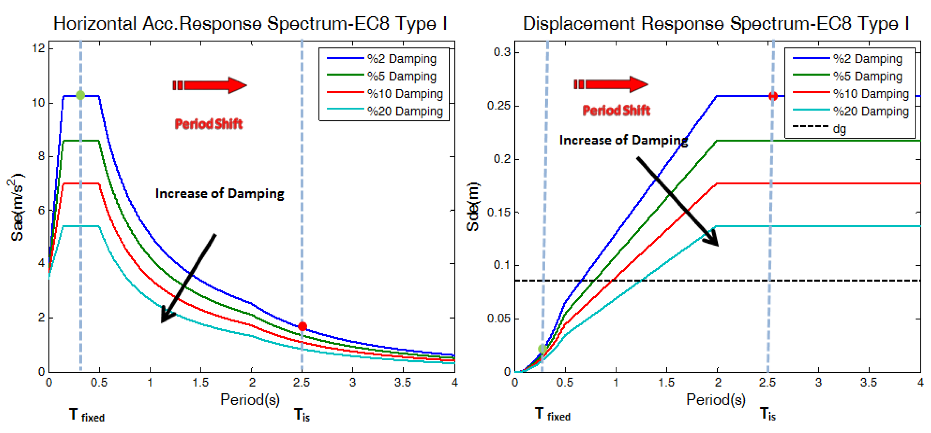
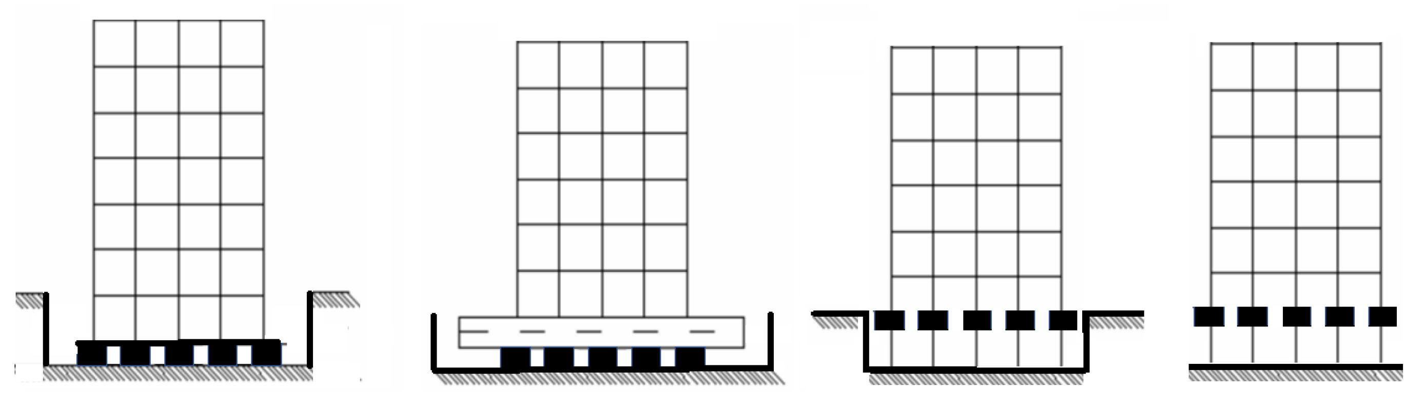
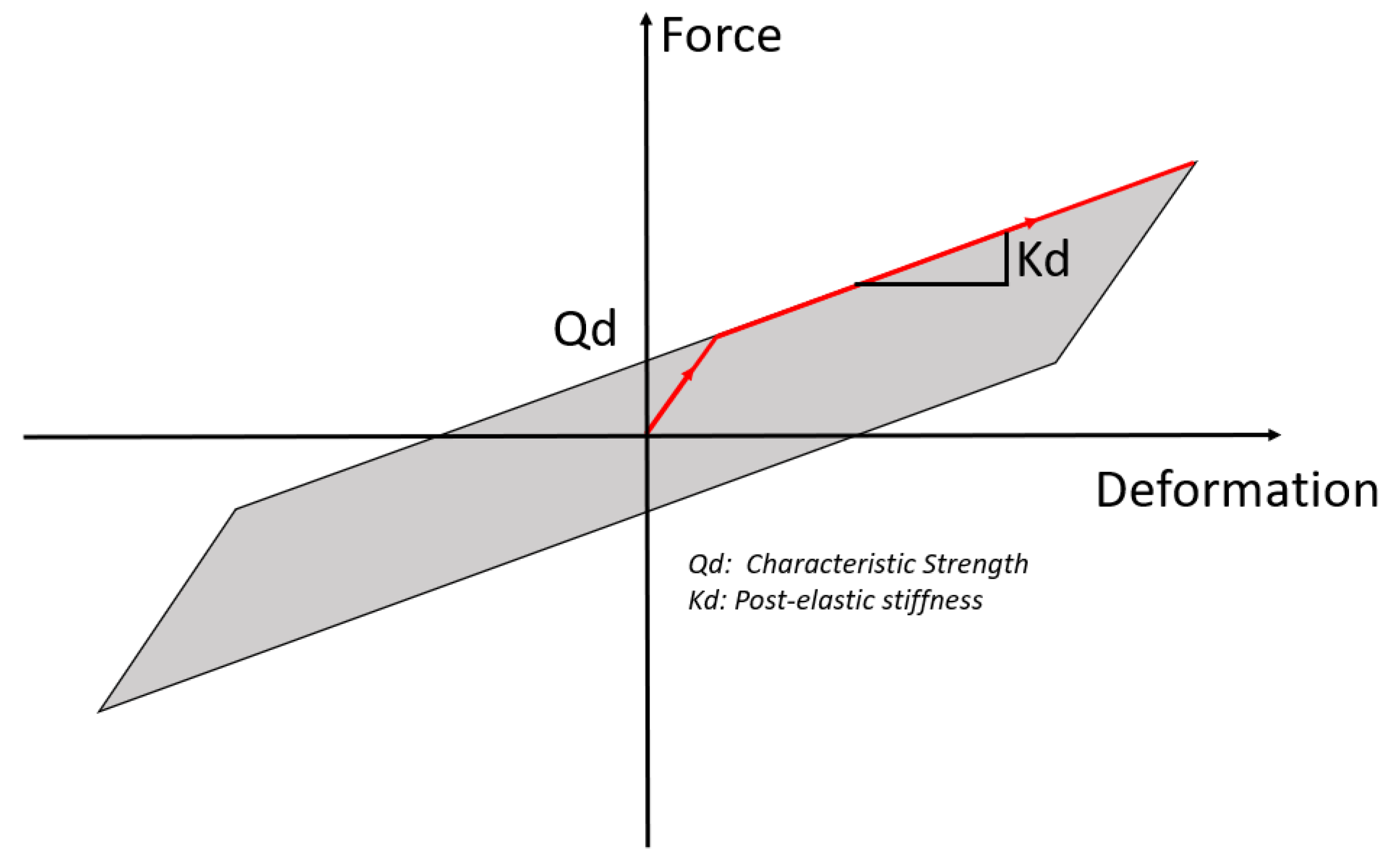
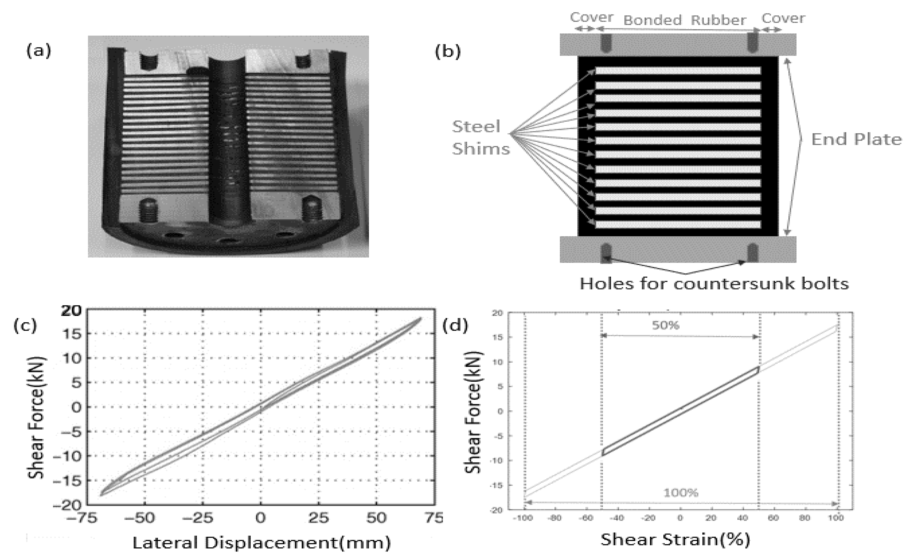
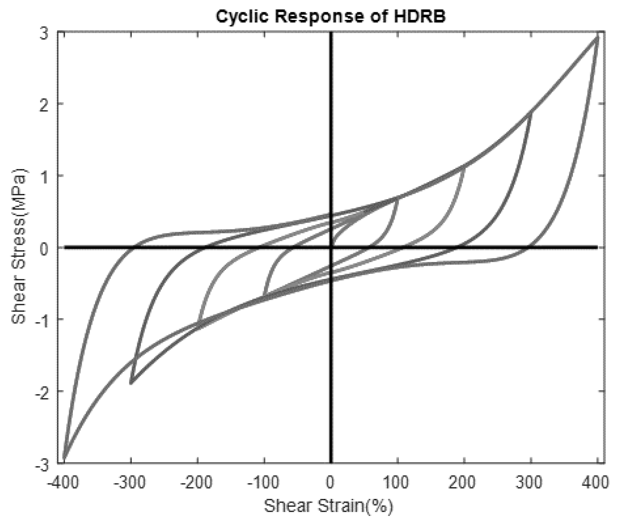
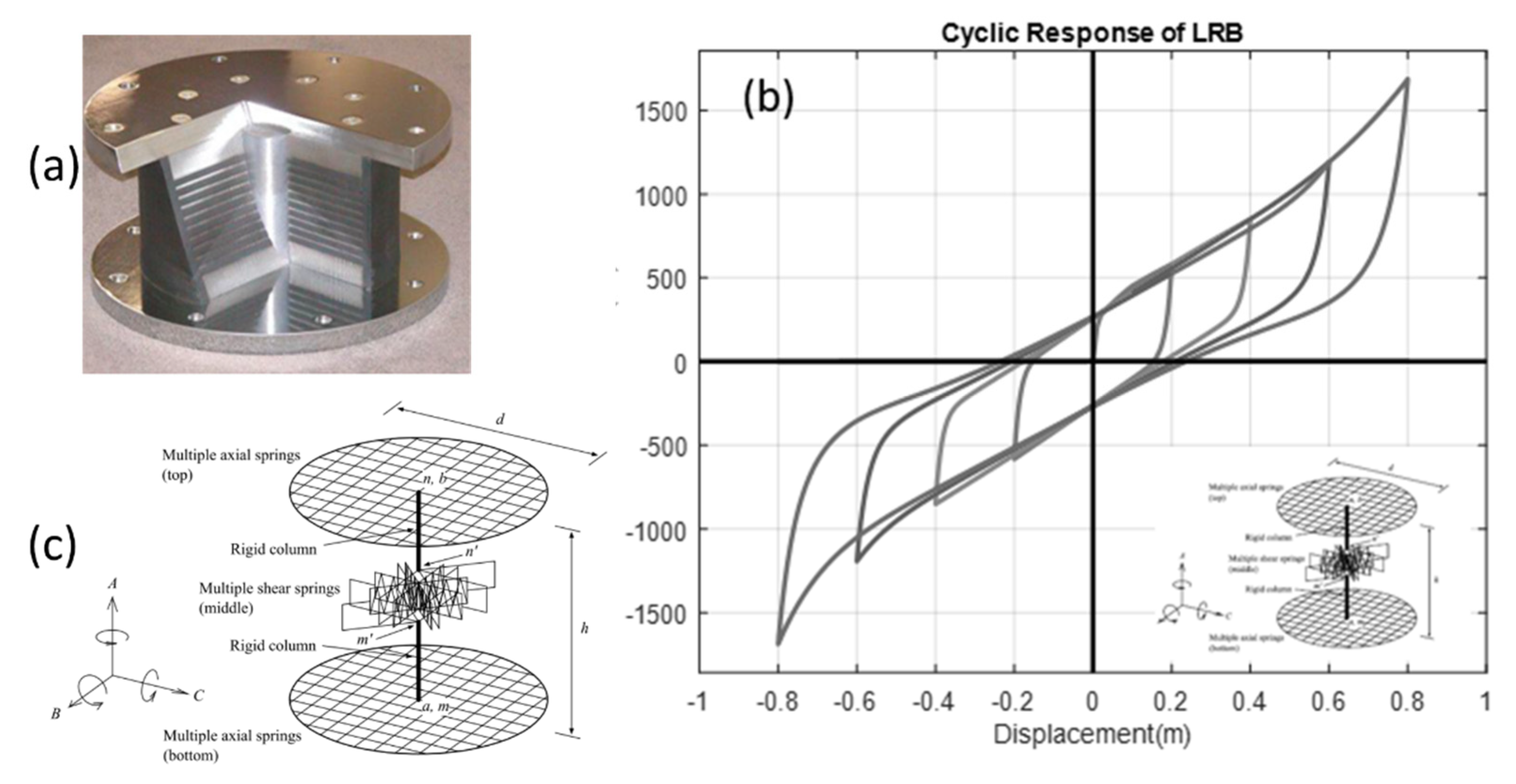
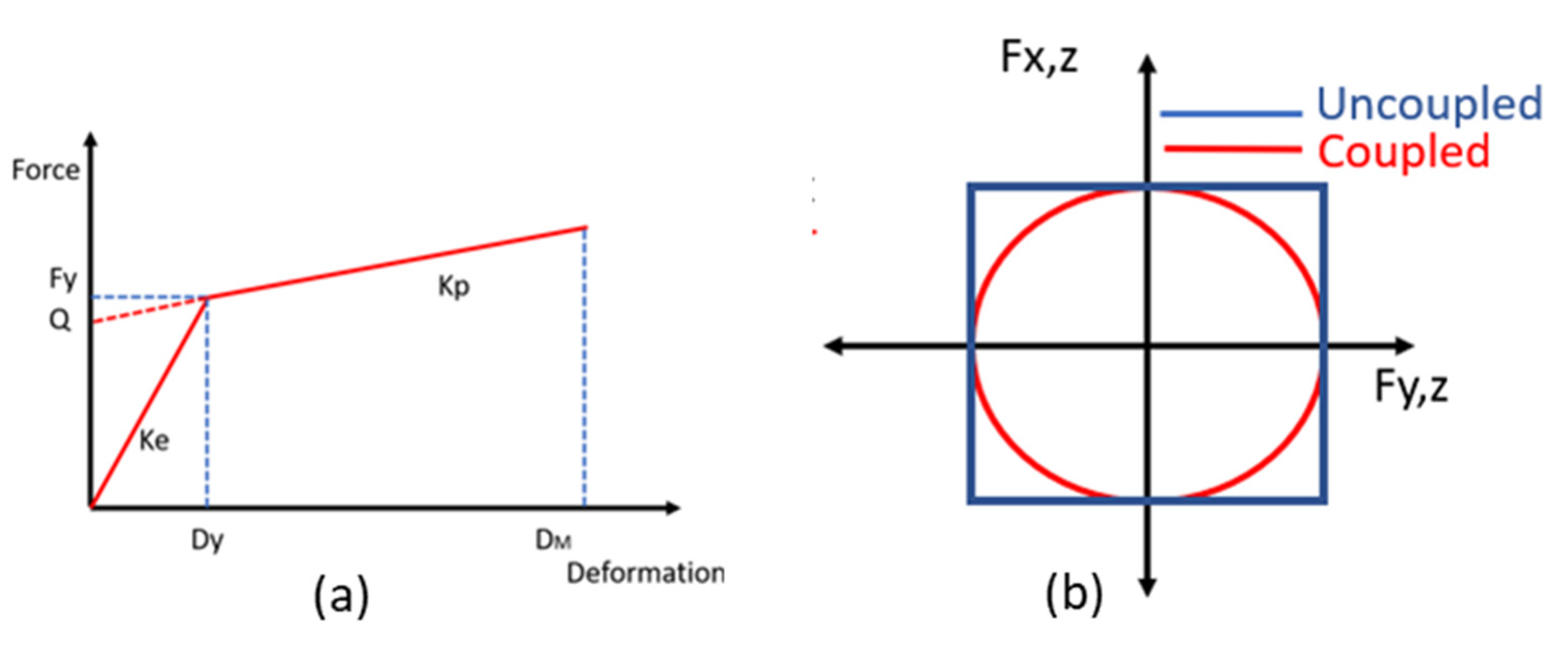
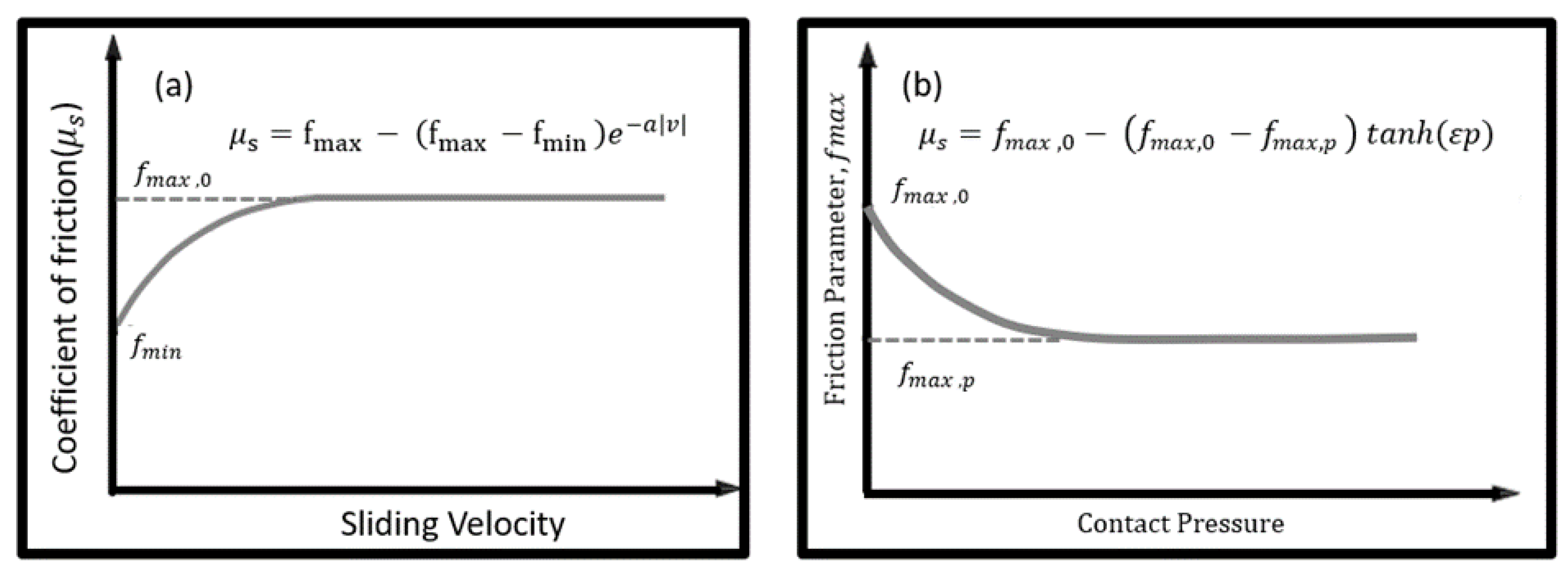
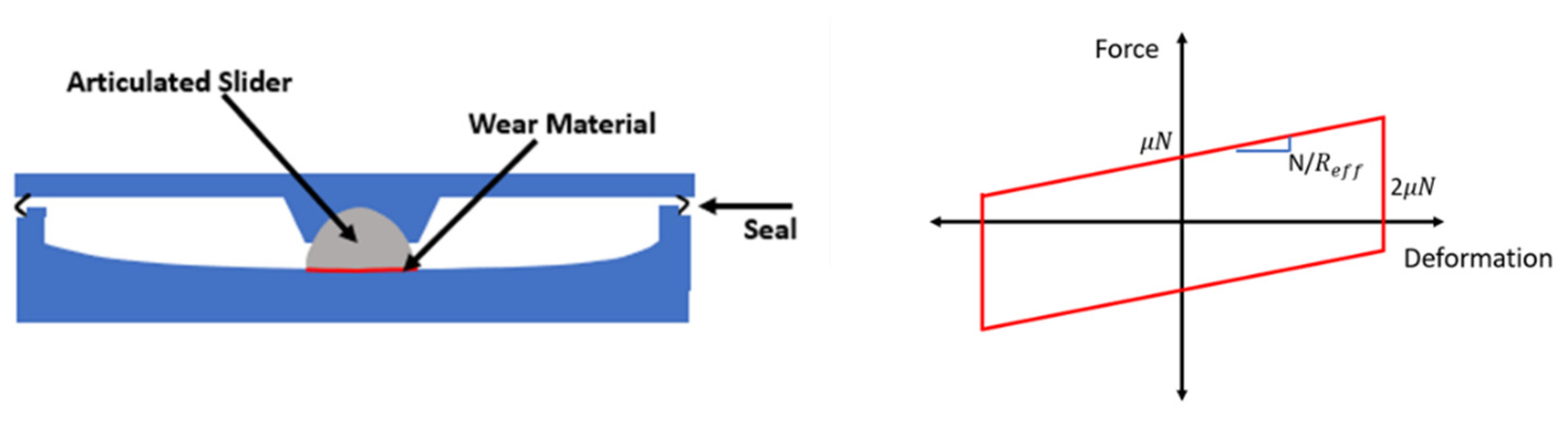
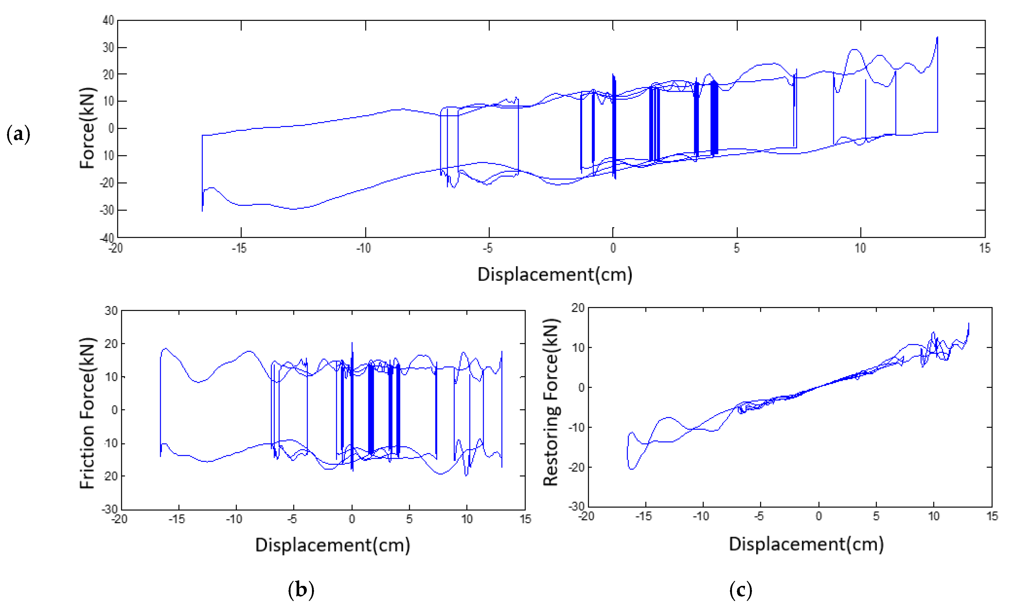
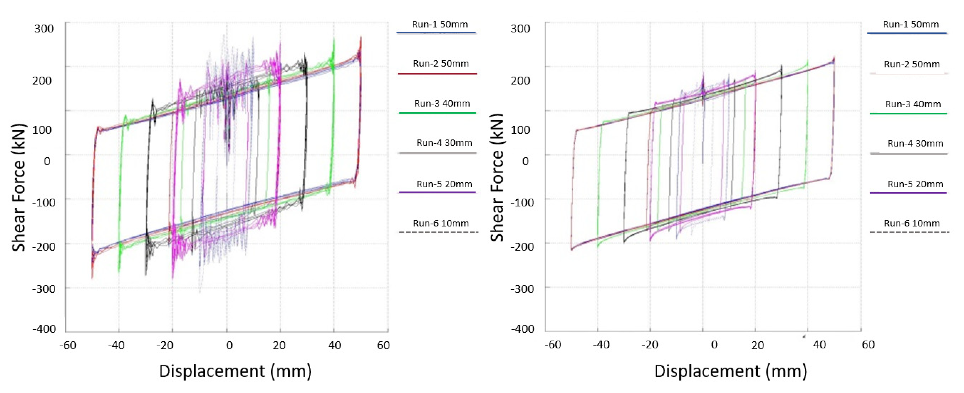
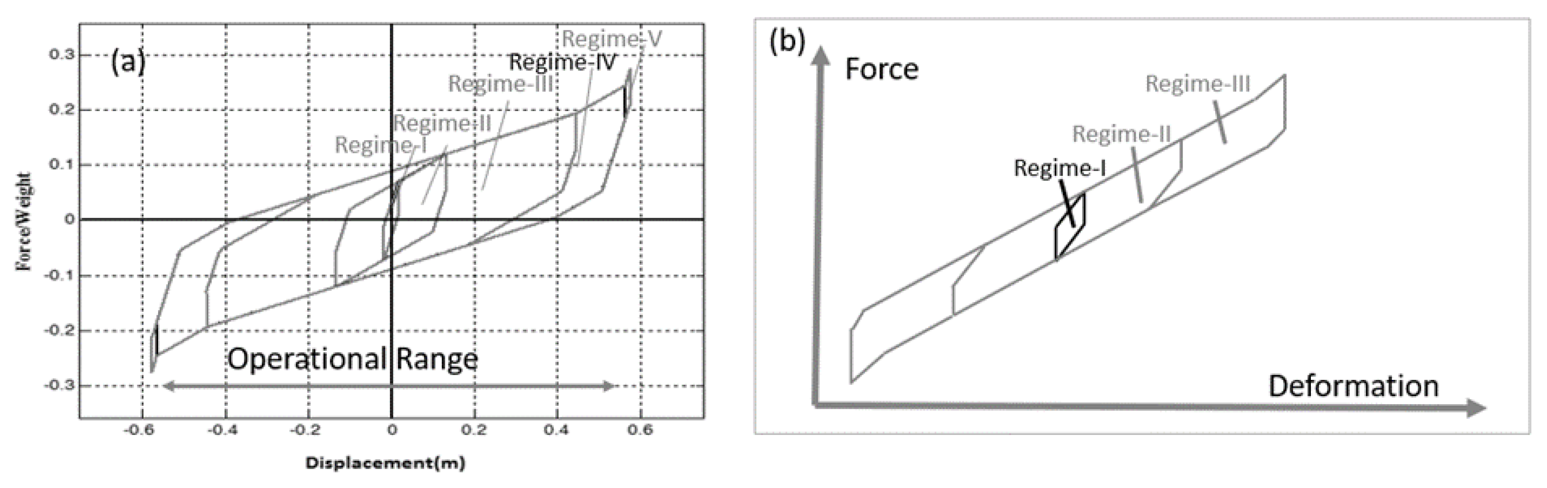
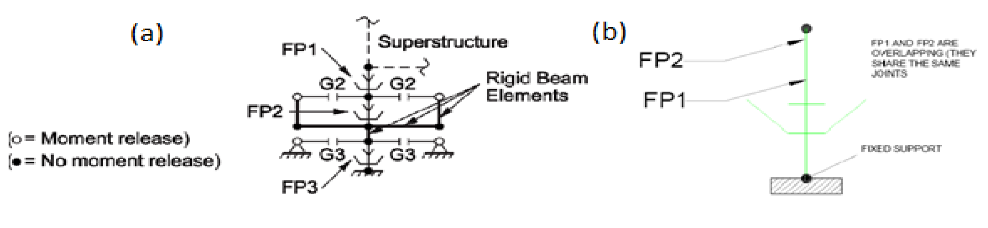
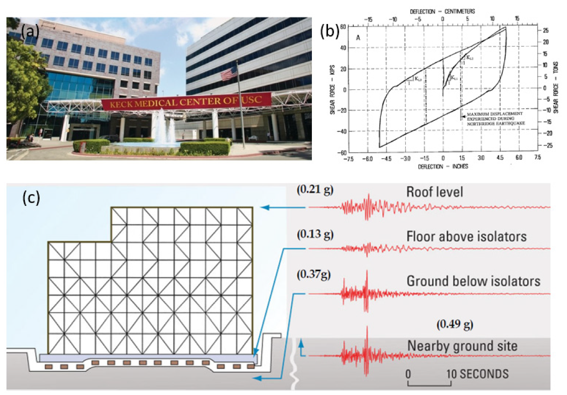
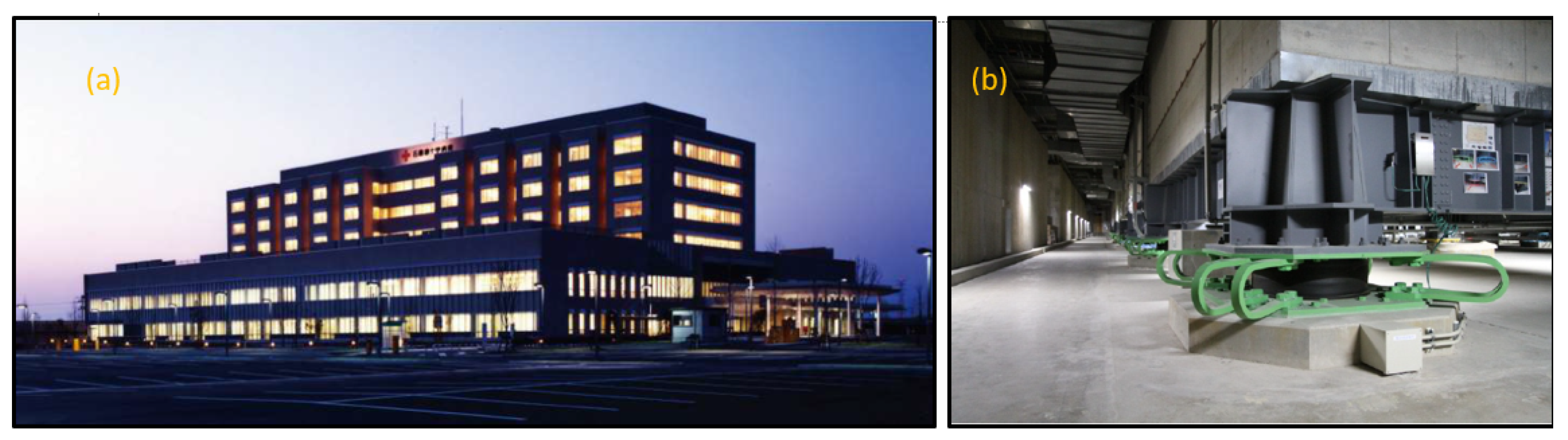
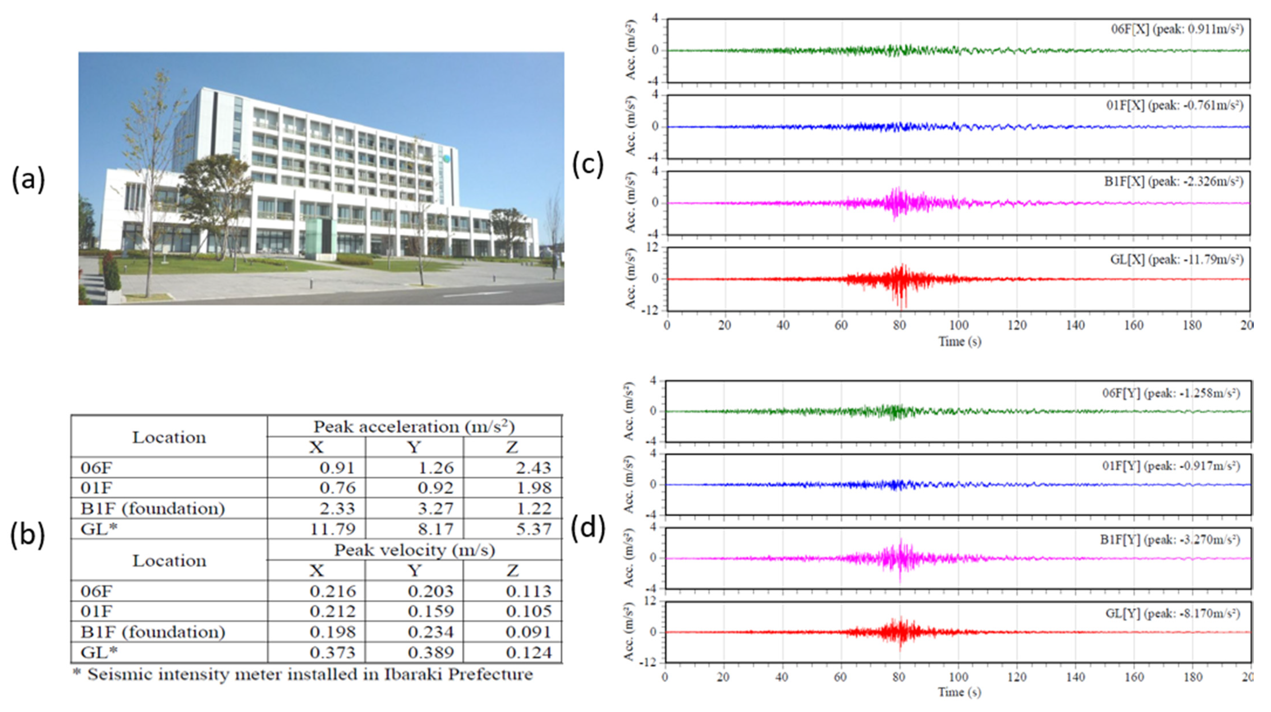
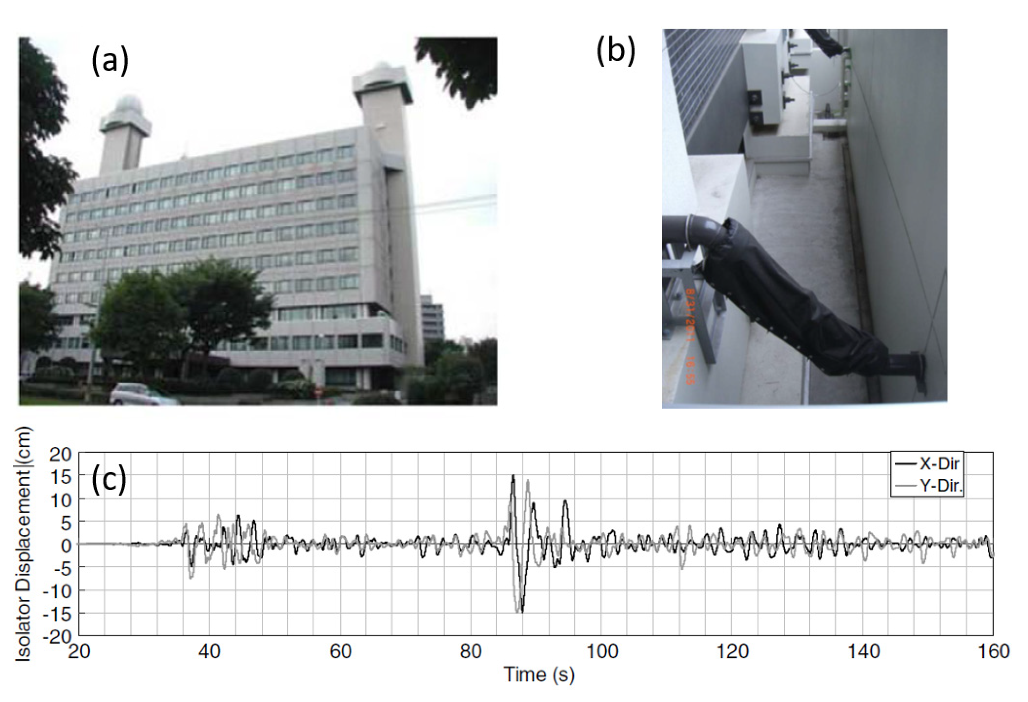
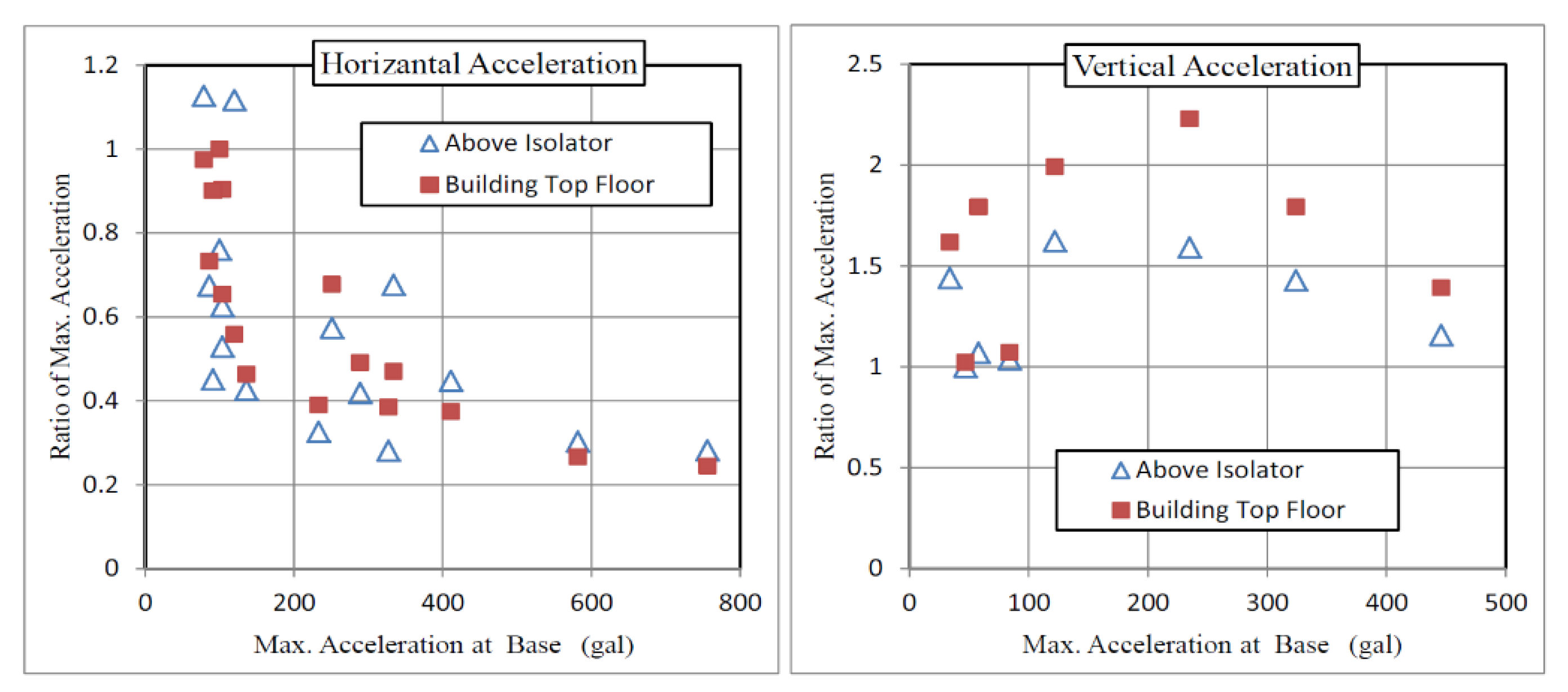
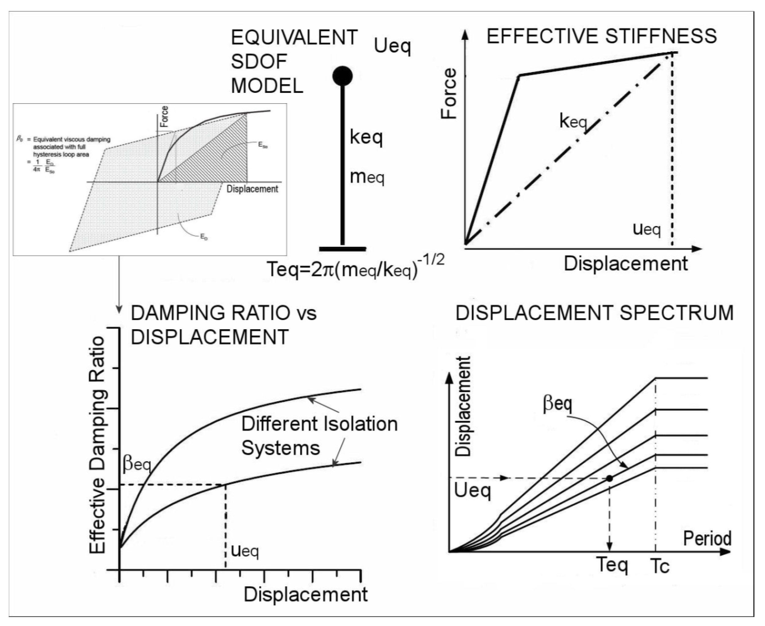
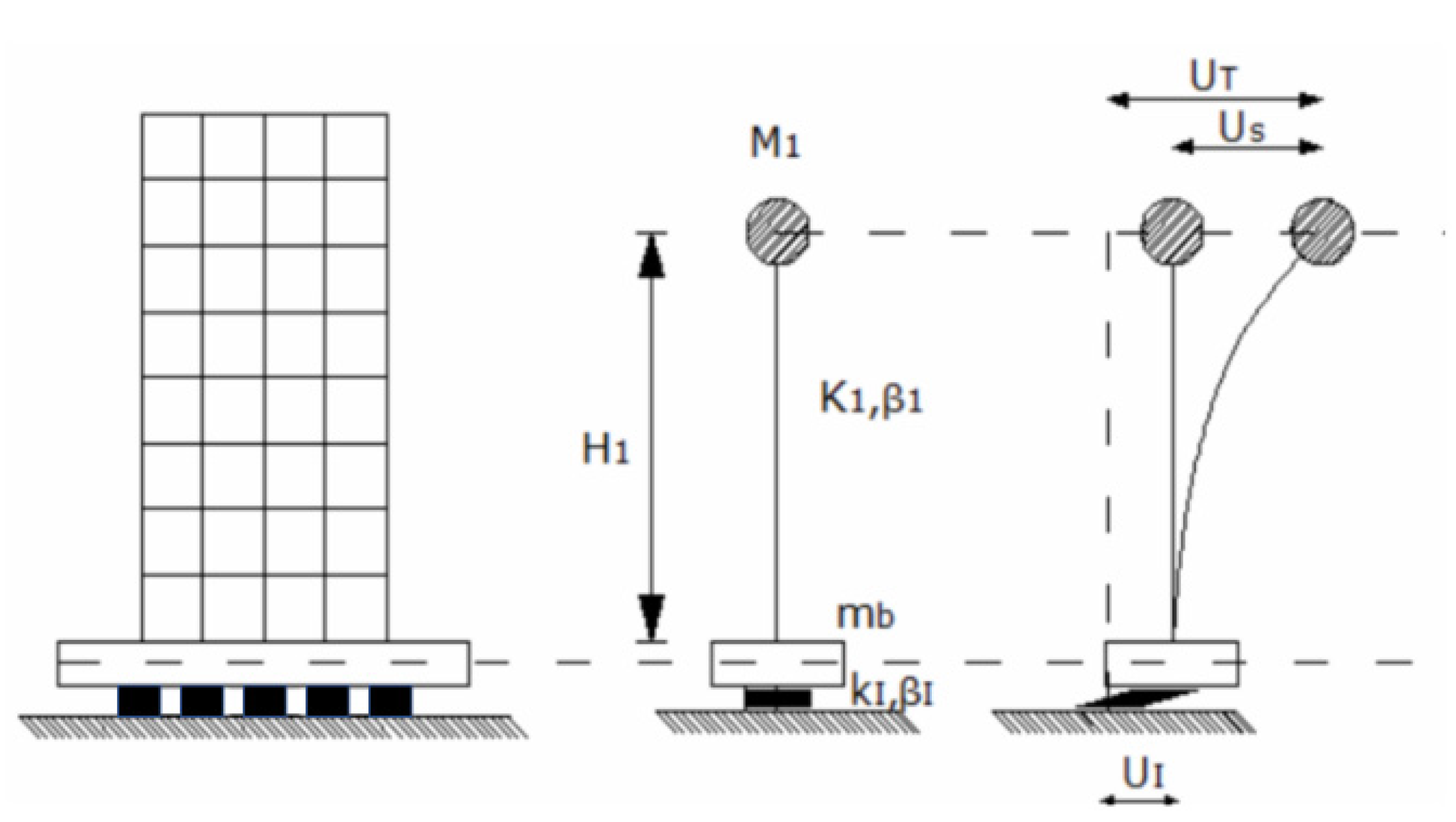
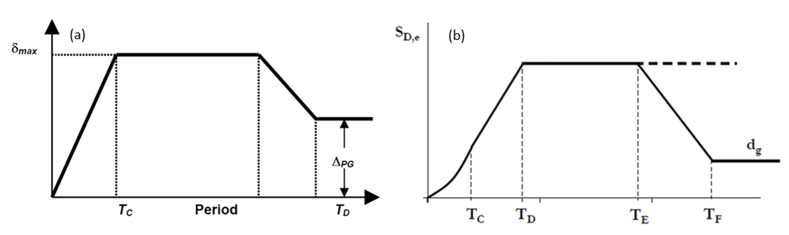
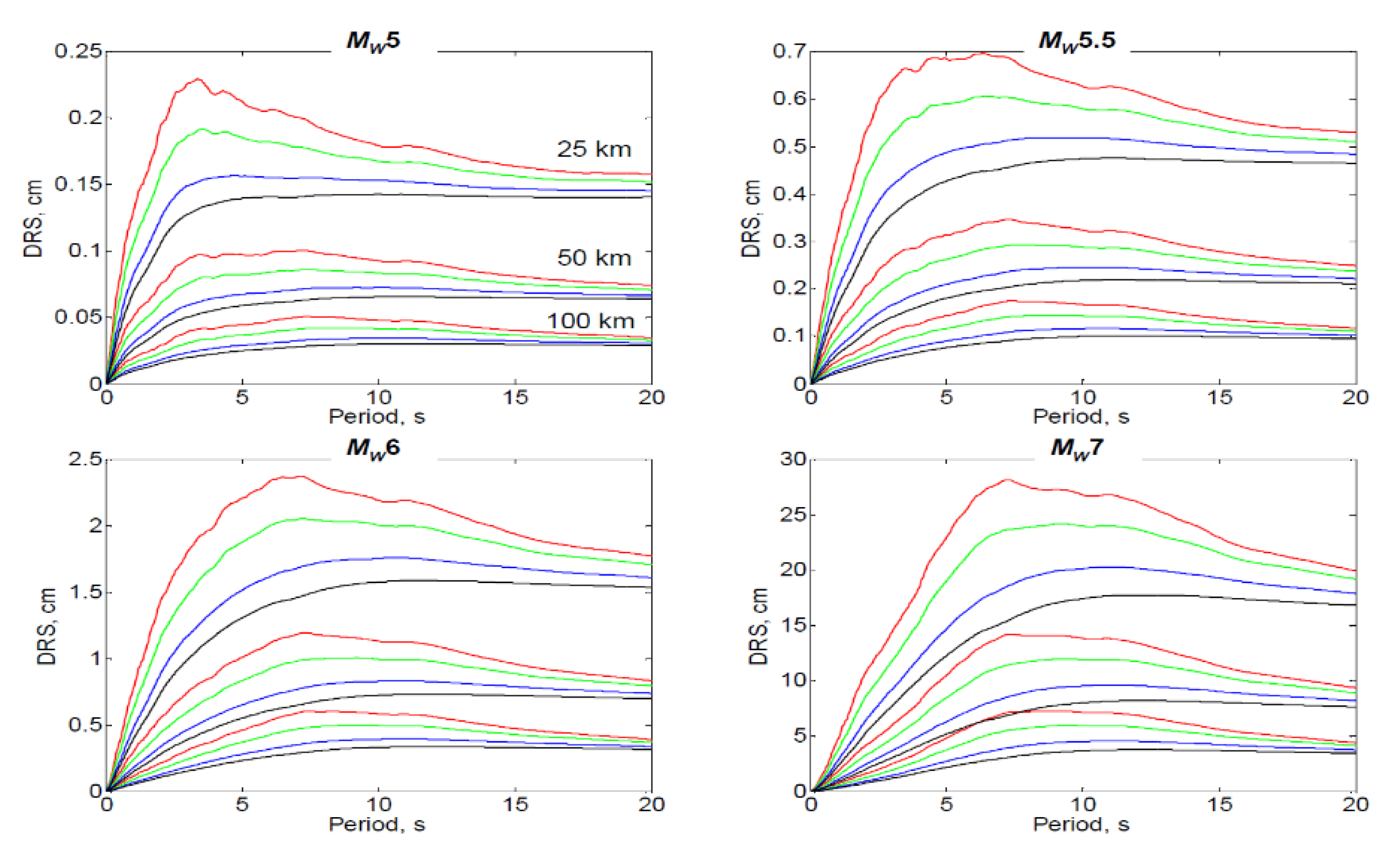
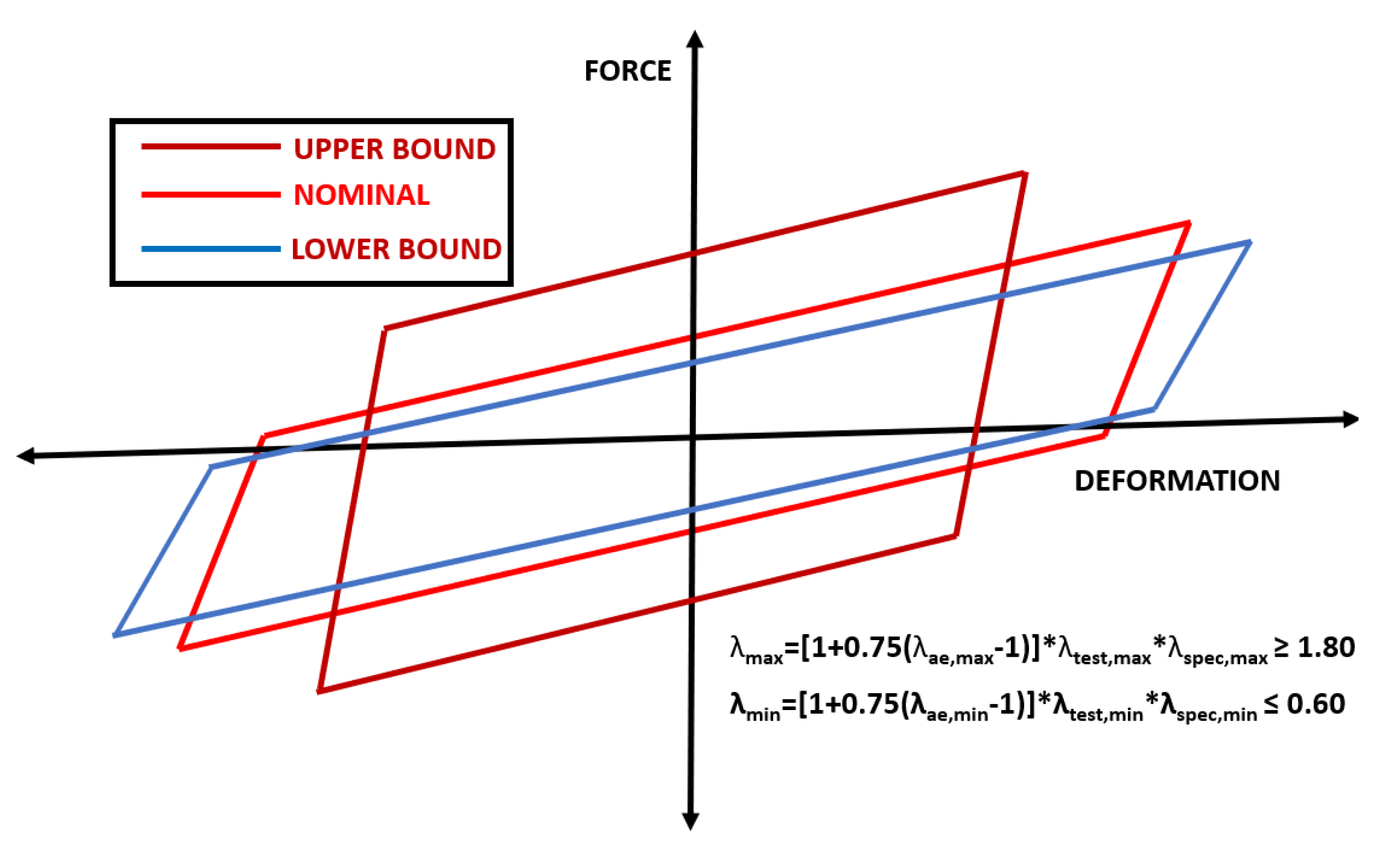
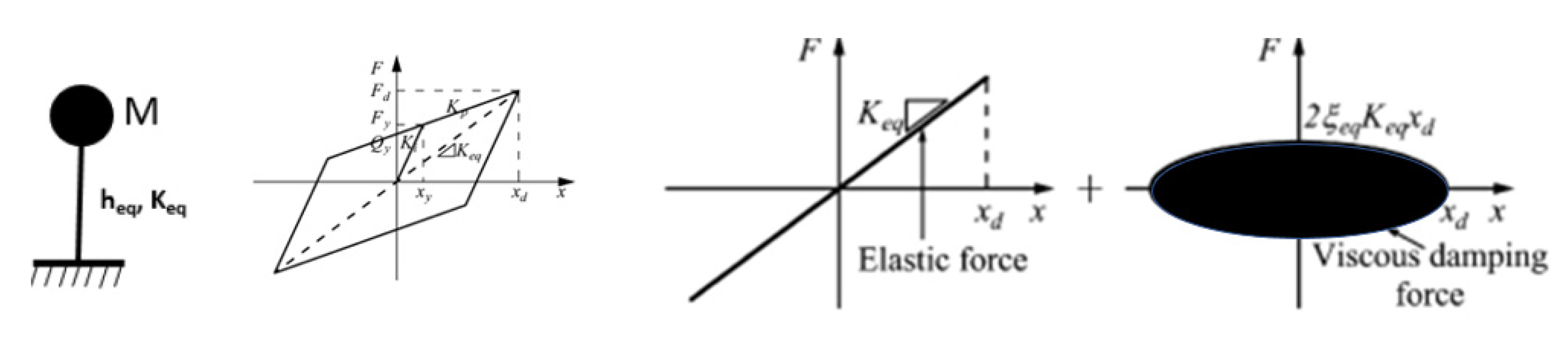
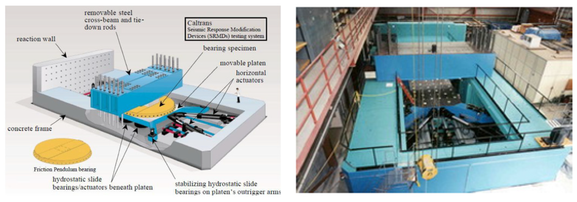
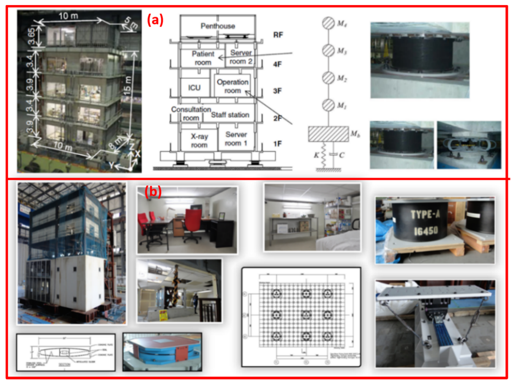
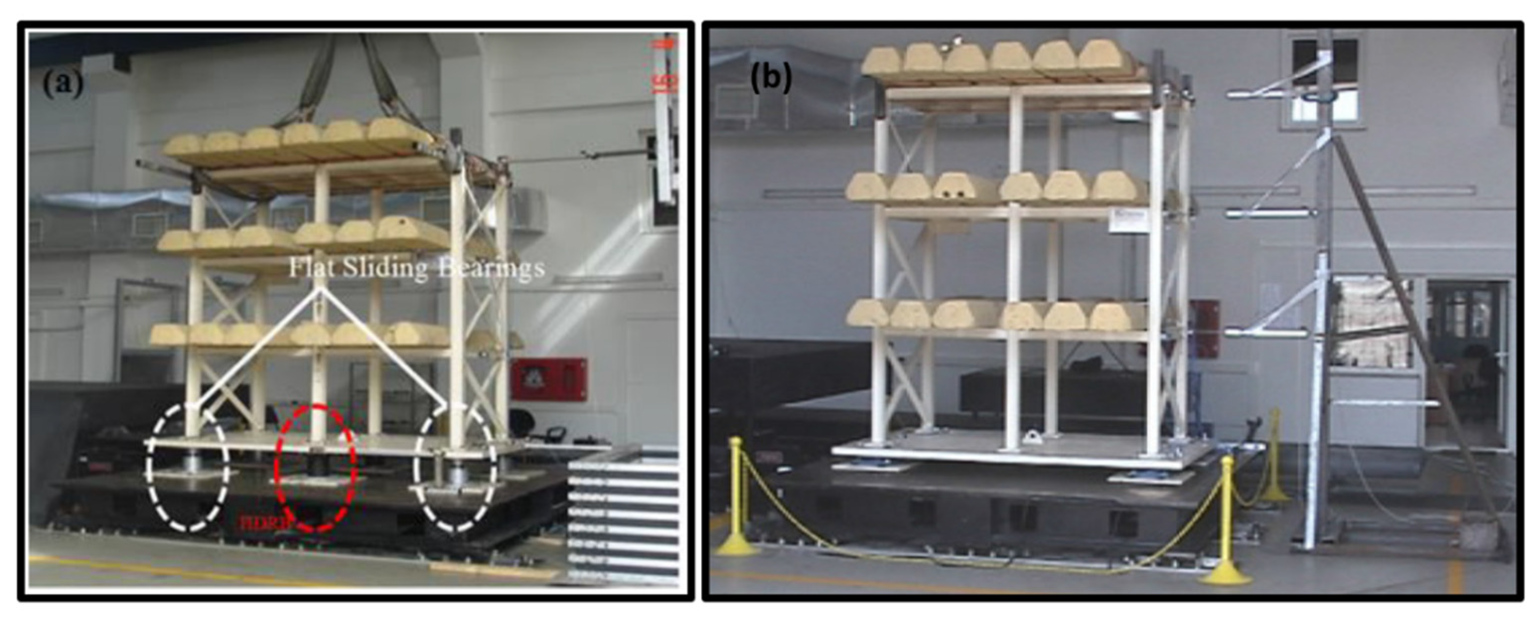
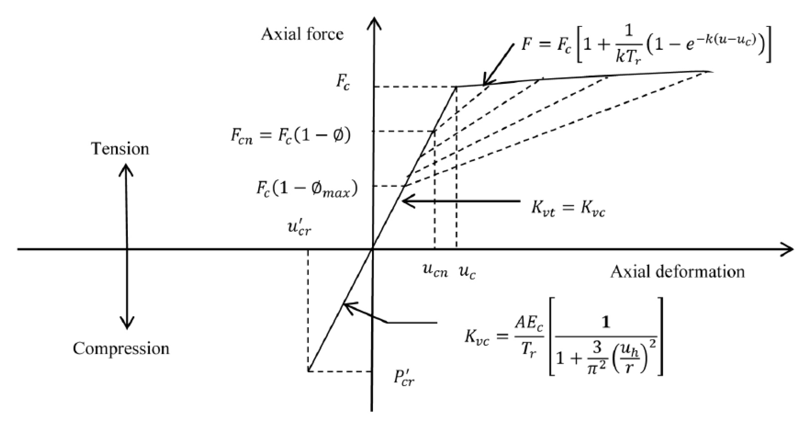
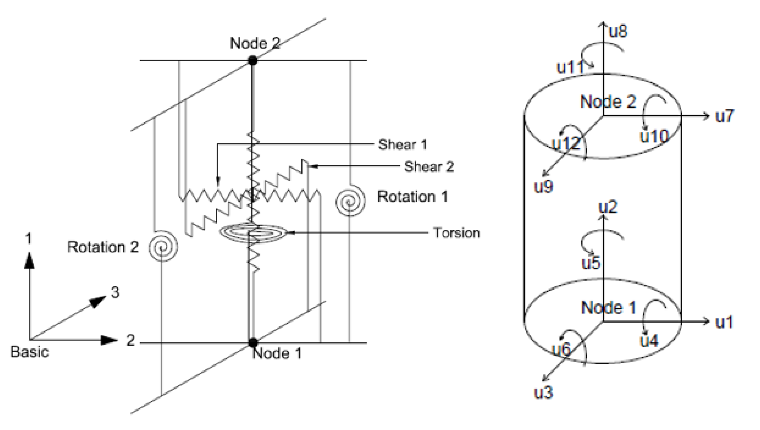
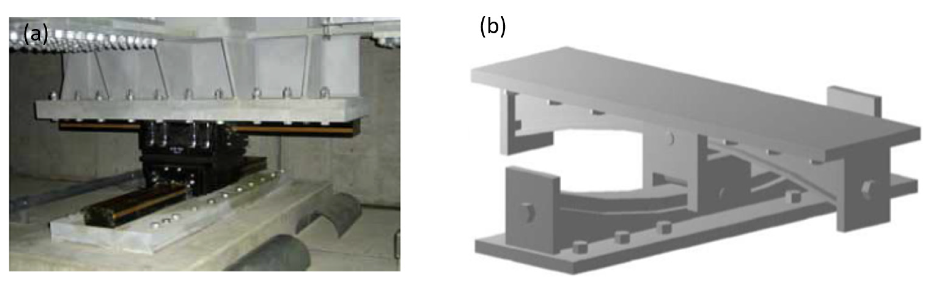
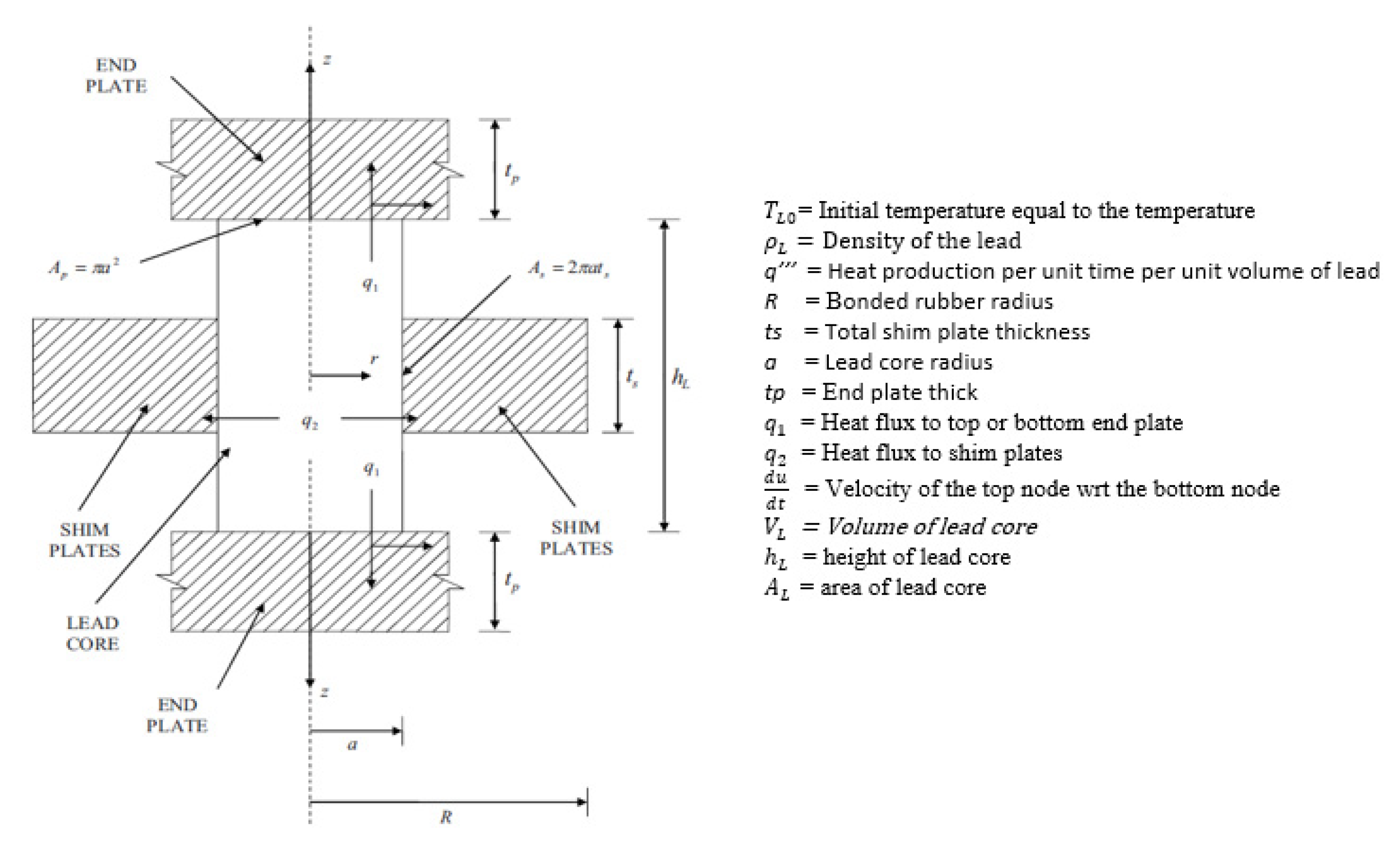
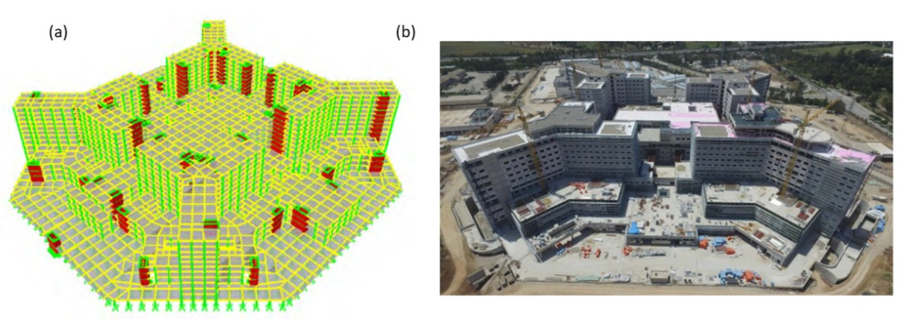
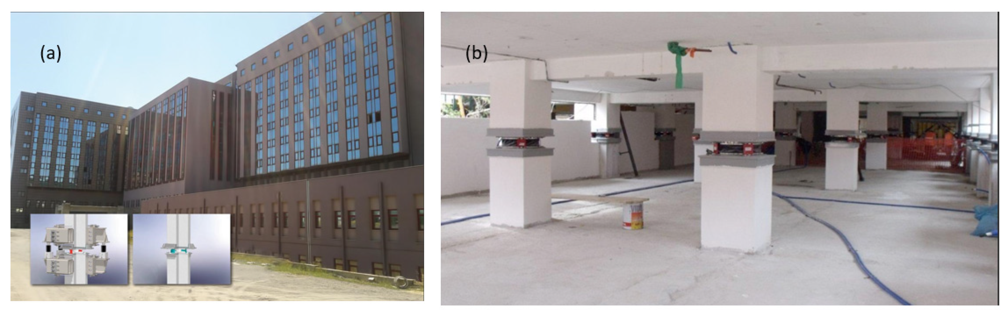
Table 1.
Limitations and essentials [85].
Table 1.
Limitations and essentials [85].
| Code | ASCE/SEI 7-16 | BSLOE-2000,2016 | NTC-08 |
|---|---|---|---|
| Limitations on site seismicity | S1 ≤ 0.6 g | ||
| Limitations on site class | A, B, C, D | 1,2 | |
| Maximum plan dimensions | |||
| Maximum height of buildings | ≤19.8 | ||
| Maximum number of stories | 4 | ||
| Location of isolation units | Base of columns | ||
| Limitations on eccentricity | 3% | 3% | |
| Kv/Ke | |||
| Tension in isolators | Allowed | Not Allowed | Not Allowed |
| Minimum yield strength | 0.03 | ||
| Period range of isolated structure | 3 | Tisol | 3 |
| Maximum vertical Period (Tv) | |||
| Importance Factor | Based on the request of control mechanism | EC8 = 1.4 NTC-08 VR (VN, CU) |
Table 2.
Parameters that are used in ELF procedure in design provisions [85].
Table 2.
Parameters that are used in ELF procedure in design provisions [85].
| Parameter | ASCE/SEI 7-16 | BSLOE-2000,2016 | NTC-08 |
|---|---|---|---|
| Effective Period ( | |||
| Characteristic Strength () | - | Min. Value = 0.03 | - |
| Displacement Demand DD, M | |||
| Effective Damping ( | |||
| Damping Reduction Factor | Tabulated Values of ≤ 1.7 | Min = 0.4; Max = 1.0 | |
| Amplification Factor for Torsion | Constant Value = 1.1 | ||
| Property Modification Factors | Constant Factor, 1.2 | EN-15129 code-requirements | |
| Base Shear | VBM = KM*DM | VBD = KDDM | VBM,D = KM,D·DM,D |
| Limitation Vertical Period | - | - | Tv ≤ 0.1 |
| Input Parameters of Spectrum | S1, Ss, TL (2-Level) | PGA | PGA |
| Displacement Safety Factor | Implicit in the definition of MCE level | Device Specific β factor (1–1.2) | 1.2 (Recommended Reliability Index Value) |
y = the horizontal direction transverse to the direction x under consideration; xi, yi = coordinates of the isolator unit i relative to the effective stiffness center; etx,y = the total eccentricity in the y direction; ry = the torsional radius of the isolation system in y and x direction;= property modification factor for aging and environmental factors;= property modification factor for heating, rate of loading and scragging;= property modification factor for permissible manufacturing variation from average value;= radius of gyration;= ratio of the effective translational period of the isolation system to the effective torsional period of the isolation system.
Publisher’s Note: MDPI stays neutral with regard to jurisdictional claims in published maps and institutional affiliations. |
© 2021 by the author. Licensee MDPI, Basel, Switzerland. This article is an open access article distributed under the terms and conditions of the Creative Commons Attribution (CC BY) license (https://creativecommons.org/licenses/by/4.0/).
Share and Cite
MDPI and ACS Style
Yenidogan, C. Earthquake-Resilient Design of Seismically Isolated Buildings: A Review of Technology. Vibration 2021, 4, 602-647. https://0-doi-org.brum.beds.ac.uk/10.3390/vibration4030035
AMA Style
Yenidogan C. Earthquake-Resilient Design of Seismically Isolated Buildings: A Review of Technology. Vibration. 2021; 4(3):602-647. https://0-doi-org.brum.beds.ac.uk/10.3390/vibration4030035
Chicago/Turabian StyleYenidogan, Cem. 2021. "Earthquake-Resilient Design of Seismically Isolated Buildings: A Review of Technology" Vibration 4, no. 3: 602-647. https://0-doi-org.brum.beds.ac.uk/10.3390/vibration4030035