
Perforated Steel Stud to Improve the Acoustic Insulation of Drywall Partitions


1
Additive Manufacturing of Functional Materials Research Group, Centre for Engineering Innovation and Research, Telford Innovation Campus, University of Wolverhampton, Telford TF2 9NT, UK
2
Additive Analytics Ltd., Telford TF3 1EB, UK
*
Author to whom correspondence should be addressed.
Acoustics 2021, 3(4), 679-694; https://0-doi-org.brum.beds.ac.uk/10.3390/acoustics3040043
Submission received: 12 September 2021
/
Revised: 3 November 2021
/
Accepted: 7 November 2021
/
Published: 9 November 2021
(This article belongs to the Special Issue Advanced Modelling, Simulations and Measurements for Sound Insulation in Buildings)
Abstract
:Steel studs are an inevitable part of drywall construction as they are lightweight and offer the required structural stability. However, the studs act as sound bridges between the plasterboards, reducing the overall sound insulation of the wall. Overcoming this often calls for wider cavity walls and complex stud decoupling fixtures that increase the installation cost while reducing the floor area. As an alternative approach, this research reveals the potential of perforated studs to improve the acoustic insulation of drywall partitions. The acoustic and structural performance is characterized using a validated finite element model that acted as a prediction tool in reducing the number of physical tests required. The results established that an acoustic numerical model featuring fluid-structure-interaction can predict the weighted sound reduction index of a stud wall assembly at an accuracy of ±1 dB. The model was used to analyze six perforated stud designs and found them to outperform the sound insulation of non-perforated drywall partitions by reducing the sound bridging. Overall, the best performing perforated stud design was found to offer improvements in acoustic insulation of up to 4 dB, while being structurally compliant.
1. Introduction
Improving sound insulation is an important consideration for the development of sustainable buildings and other products [1,2,3,4,5]. Generally, high mass building walls are often recommended for noisy areas to achieve enhanced sound insulation [6,7]. However, lightweight steel stud walls can often offer equal or better performance if sound insulation performance is considered as a criterion at their design stage [8,9,10]. Drywalls composed of lightweight steel studs and gypsum plasterboard walls are an inevitable component of efficient building design due to their low construction costs [11]. While the studs offer excellent structural stability for the wall, they act as sound bridges offering a direct path between the partitions, reducing the overall sound insulation rating. Consequently, improving the sound insulation of drywall partitions by improving conventional studs are critical in reducing sound bridging without the need for costly alternatives [12,13].
Various efforts to reduce the sound transmission through the wall are available in the literature [14,15,16]. However, strategies to improve the sound insulation of stud walls through perforated webs are yet to be investigated. The most common technique that is currently used is to increase the thickness of the plasterboards, at the expense of reduced floor area and increased cost [17,18]. Furthermore, increasing the overall thickness of building walls in addition to reducing the sound transmitted through structural links will yield the furthest improvement in the overall acoustic rating of the wall.
Acoustic studies evaluating the influence of various parameters of drywalls such as mass, stiffness and width of the plasterboard in addition to the type of infill material and stud types are available in the literature [19,20,21,22,23]. When it comes to reducing the effect of the studs, the focus is generally on modifying the connections between plasterboards and studs [24,25,26]. Overall, some parameters have been extensively studied, while others rarely addressed, such as the influence of perforated studs. This is largely due to the difficulty in characterizing their performance using simplified models and the challenges in physical experimental characterization while accounting for measurement uncertainties [27,28,29].
For characterizing the sound insulation of stud walls, the parameters of interest are the frequency depending sound reduction index (R) and the single number ratings [30,31,32]. While the R-value is useful in characterizing the sound insulation of the wall at 1/3rd octave frequency bands, providing a single number rating requires the weighted sound reduction index () and the spectrum adaptation terms C and [33,34,35]. The weighted sound reduction index is primarily used for comparing the sound insulation offered by different building materials and structures. An explanation of the relevant single number rating to characterize sound insulation used in this study are summarised in Table 1. However, it should be noted that as stated in ISO717-1 [36], the use of the various parameters are much broader than this type of wall. In particular is a single number rating that can be complemented if relevant or prescribed for a specific situation.
Looking at prediction models for sound insulation suitable for building walls, the vast majority do not consider studs or structural links between the plasterboards [18,37,38]. However, work by Wyngaert [39] developed a model with finite walls and flexible frames demonstrating reasonable accuracy in comparison to experimental tests. Other notable models that consider structural links include Lin and Garrelick [40], Takahashi [41], Skelton [42] and Arjunan et al. [43]. While these models considered the existence of structural connection, the use of a perforated web and the resulting fluid-structure-interaction (FSI) is yet to be considered. As such, this study explores the use of the finite element method (FEM) in such a way that all geometrical complexities of the stud are considered including web perforations. The challenge of using FEM is the computational cost as the solution time is proportional to the complexity of the model, FSI and the frequency range considered [44,45,46,47].
For the finite element acoustic models to be suitable as a design tool to characterize the sound insulation, a validated model taking into consideration the finite geometry of the wall and studs is required. This model should also be capable of predicting the characteristic sound insulation terms as described in Table 1. To accomplish this, the acoustic model should consider a 1/3rd octave frequency range between 100 Hz and 3150 Hz with sufficient accuracy in comparison with experimental test data [16,48].
This study characterizes the acoustic insulation of plasterboard partitions featuring studs with the perforated web. Altogether the performance of six different perforation configurations keeps the ratio of perforated to non-perforated area constant. This means that all perforation configurations have an equal amount of materials being removed while featuring different arrangements. The C-channel cross-section that is commonly used in the UK construction industry informed the global geometry of the stud. The finite element modelling procedures presented in this study are validated using experimental test results complying ISO 10140-1:2021 [49]. Lastly, the effect of the perforation configurations on the structural stability of the wall is also characterized in compliance with BS 5234 [50]. Overall, the study reveals the potential for stud improvements that can increase sound insulation for non-load bearing partition walls.
2. Materials and Methods
2.1. Finite Element Acoustic Model
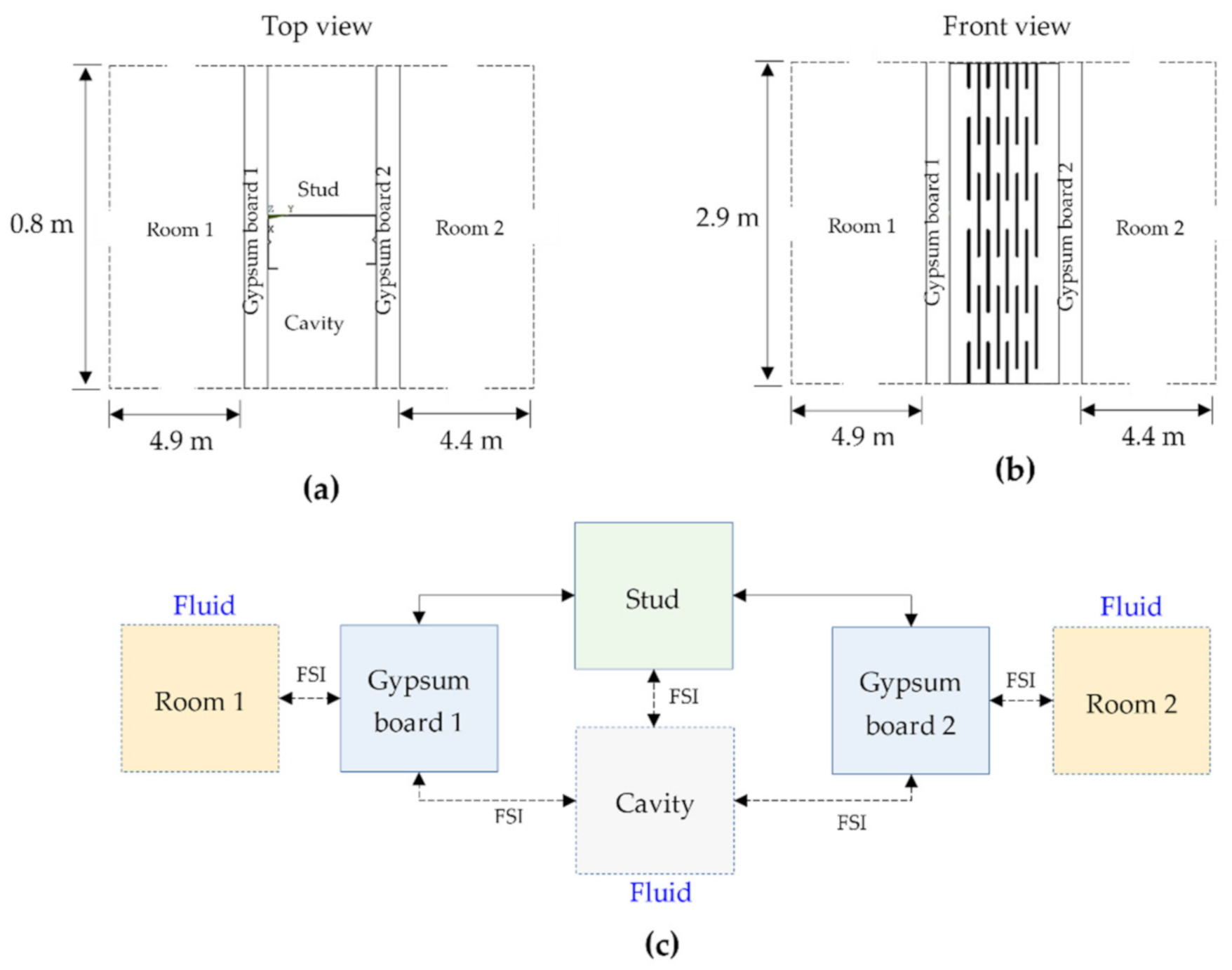
Previous studies [12,14], have shown the suitability of room-wall-room acoustic models for predicting the sound reduction index of partition walls. As such, the stud wall for this study was modeled using an accurate description of the geometry placed between a two-room setup. The components of the overall model and the dimensions are as shown in Figure 1. As highlighted other than for the connection between the stud and the gypsum plasterboards, all other interfaces are modeled with FSI elements that feature both the acoustic pressure and structural displacement as boundary conditions.
A 3D finite element model with global dimensions as shown in Figure 1 was developed using the Ansys Parametric Design Language (APDL) featuring custom subroutines in Fortran programming language. The room-wall-room model used to simulate the acoustic insulation requires FSI at the interfaces between ‘room and gypsum board’ and ‘gypsum board and cavities’ as highlighted in Figure 1c. To establish FSI, the structural dynamics equation along with the Navier-Stokes equations of fluid momentum and the flow continuity equation are required to be considered [51]. The discretized structural dynamics equation can be formulated using the structural elements as shown in Equation (1):
where , and are the structural mass, damping and stiffness matrix, respectively. , and are the nodal acceleration, velocity, and displacement vectors, respectively. In addition, is the applied load vector. Assuming that the fluid is compressible and inviscid with uniform pressure and density with no mean flow, the fluid momentum and continuity equations can be simplified to get the acoustic wave equation as shown in Equation (2):
where , is the speed of sound, is the mean fluid density, is the fluid bulk modulus, is the acoustic pressure and is the time. The speed of sound and fluid density are input as part of the material properties for the fluid element ‘Fluid30′ used to model Room 1, Room 2 and Cavity as shown in Figure 1c. The data input labels used are SONC and DENS under command reference MP (Material Properties) for the speed of sound and mean fluid density, respectively. Since the pressure is harmonically varying (), Equation (2) reduces to Equation (3) which is the Helmholtz equation:
where is the pressure amplitude and . Using the gradient and divergent matrix operator shown in Equations (4) and (5), respectively, Equation (2) can be transformed into matrix notation as shown in Equation (5):
Subsequently, the element matrices are derived by discretizing Equation (6) following the Galerkin procedure discussed by Bathe [52]. Multiplying Equation (6) by the virtual change in pressure and integrating over the volume of the domain as proposed by Zienkiewicz and Newton [53] yields:
where is the domain volume, is the virtual change in pressure (, is the surface where the derivative of pressure normal to the surface is applied (a natural boundary condition) and is the unit normal to the interface .
Since the problem under consideration requires FSI at the interface of the gypsum board with the room and the stud with the wall cavity, the surface is treated as the interface. As such the fluid momentum equations result in the following relationship between the normal pressure gradient of the fluid and the normal acceleration of the structure at the fluid-structure interface as shown in Equation (8) [53], which can be transformed into matrix notation as shown in Equation (9).
Substituting Equation (9) in Equation (7), the integral for the coupled problem that contains the fluid pressure and the structural displacement vector at the interface as dependent variables can be obtained:
2.2. Material and Element Properties
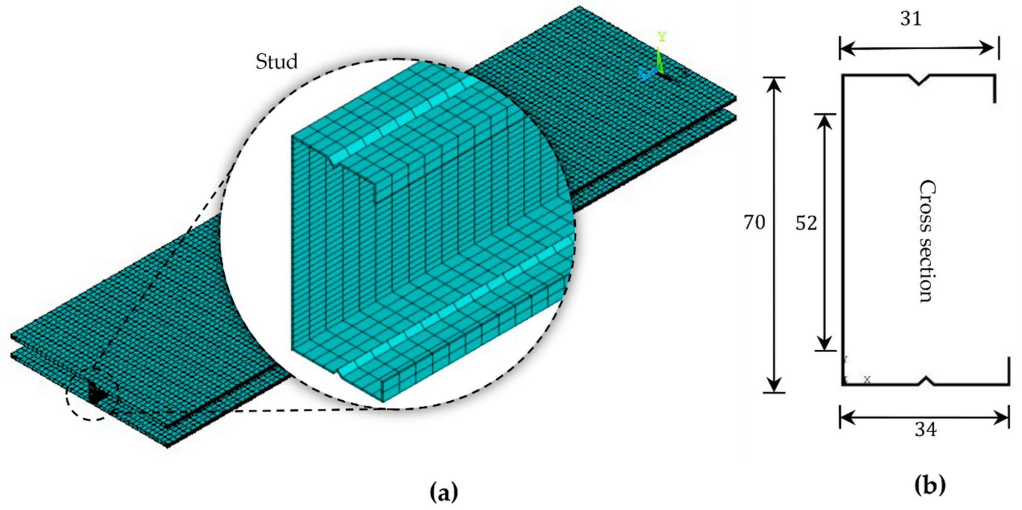
The geometrical model features two 15 mm gypsum plasterboards on either side of a C-channel 0.5 mm steel stud of width 70 mm as shown in Figure 2. The wall was modeled as the partition between Room 1 and Room 2 which are acoustic fluid volumes of relevant dimensions as shown in Figure 1. The structural components of the system that include the gypsum board and the stud was modeled using the Solid185 element which has 8 nodes. The acoustic fluids that are not directly in contact with structural elements were modeled using Fluid30 with only a pressure degree of freedom. The interface areas experiencing FSI were modeled using Fluid30 with both pressure and displacement degrees of freedom as shown in Equation (10). A mesh convergence was carried out and found that the best results at 1/3rd octaves were observed when the mesh size satisfies at least eight elements per wavelength. This resulted in a model averaging 1,550,400 elements and 1,574,539 nodes taking approximately 91 h to complete the simulation at 1/3rd octave band frequency range. The model was solved using 54 CPUs at 2.4 GHz with parallel processing switched on.
Boundary conditions mimicking the experimental test setup were specified to carry out the harmonic acoustic analysis using FEM. The displacements at all external boundary nodes for Room 1 and Room 2 were constrained to zero. The structural elements of wall partitioning the two rooms were allowed to vibrate in response to the forces from the fluid pressure in the rooms. The top and bottom end of the stud were also constrained to zero displacement to ensure that the studs remained in their designated positions throughout the simulation. Fluid elements replicating the room air were allowed to resonate freely within the system. To simplify the model and provide a uniform mesh, the screw fixings between the stud flanges and gypsum boards were modeled through node merging. A FSI boundary condition was specified at all fluid-structure interfacing elements.
The sound source was a frequency-dependent harmonically varying displacement of 0.1 mm in Room 1 representative of a broadband acoustic diaphragm. The size of the oscillation of the sound source itself is insignificant since the sound pressure level was measured by averaging spatial acoustic fluid pressure over the whole room volume at one-third octave band. To avoid spurious effects, three excitation frequencies ranging from 5% of each of the central frequencies of the 1/3rd octave band have been considered. The sound pressure level difference was then evaluated between the average sound pressure levels obtained between Room 1 and Room 2.
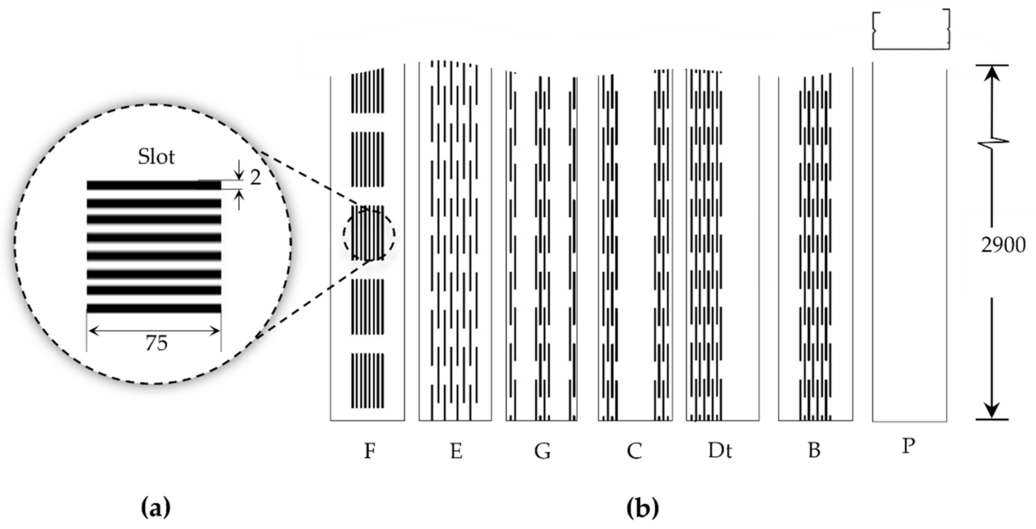
The acoustic analysis of the wall was conducted using a non-perforated configuration (P) in addition to six different perforation configurations as shown in Figure 3. All perforation configurations were designed to keep the ratio of the perforation to the non-perforation area constant. This ensured that the amount of material for all perforated studs was constant. The nonperforated studs were designated P and the perforation configurations were designated F, E, G, C, Dt and B signifying various perforation arrangements as shown in Figure 3b. All material properties used for the numerical model are as summarised in Table 2.
To evaluate the flexural stiffness, all the stud designs were subjected to a pressure of 5.5 kPa distributed along the stud flange that is in contact with the source room. The studs were constrained at the ends and the maximum bending along the transverse direction was recorded. Subsequently, Hooke’s law was used to evaluate the flexural stiffness of the stud sections. The structural compliance of the walls was evaluated through a non-linear structural analysis that simulated the ability of stud wall assembly to withstand people or ladders leaning against it without causing unacceptable deformation. The test scenario for this was designed to closely mimic the ISO5234 [50] and ASTM C754 [54] guidelines. According to the standard, the deflection of the wall under a lateral load of 240 Pa at the center must not exceed a lateral displacement of /240, where is the total length of the stud which is 2.9 m.
2.3. Experimental Test
Physical tests of the stud-wall featuring identical dimensions to the finite element model were conducted at the Sound Research Laboratories (SRL), UK. The gypsum boards were screwed to the studs at 300 mm spacing along the length. The samples were mounted, positioned, and tested in accordance with ISO10140 guidelines, and the measurements returned a level of confidence of approximately 95% consistent with acoustic measurements at 1/3rd octaves.
Similar to the numerical technique, the sound insulation was characterized by the difference in sound pressure levels measured across the test sample installed between two reverberant rooms. The difference in measured sound pressure levels was corrected for absorption in the receiving room. The test is done under conditions that restrict the transmission of sound by paths other than directly through stud wall partitions under a random incident sound field. Broadband noise was produced in Room 1 using a dodecahedron speaker and the resulting sound pressure levels in both rooms were sampled, filtered into 1/3rd octaves, integrated, and averaged using a real-time analyzer using microphones on an oscillating boom.
The difference in sound pressure level across the stud wall is the Sound Reduction Index (R) calculated using Equation (11) [55]. and are the sound pressure levels in Room 1 and Room 2, respectively, in decibels (dB), is the equivalent absorption area of Room 2 and S is the area of the dividing partition (). The sound pressure level in each room can be expressed using Equation (12), where P is the sound pressure in the room and is the reference sound pressure which is 20 × 10−6 Pa.
3. Results and Discussion
3.1. Validation of the Acoustic Model
Within the finite element framework, the acoustic FSI model is conceived as a room-wall-room framework considering anechoic termination at the boundaries. The model is used to predict the sound insulation of the drywall composed of plain and perforated studs sandwiched between two gypsum plasterboards of finite thickness. The sound originating room (Room 1) and the transmitted room (Room 2) are both modeled with elements featuring fluid pressure , while the elements in contact with the wall are modeled with the displacement components , and in addition to . As such, the finite element shape function for the spatial variation of the acoustic pressure and displacement was modeled as shown in Equations (13) and (14), respectively:
where and are the element shape function for pressure and displacement, respectively. is the nodal pressure and are the nodal displacement component vectors , and . From Equations (13) and (14), the second time derivative of the variables and the virtual change in the pressure was derived as shown in Equations (15)–(17):
when the matrix operator applied to the element shape function , the expression becomes Equation (18):
Substituting Equation (13) through (18) and into (12), the finite element expression of the wave equation can be written as:
where {n} is normal at the fluid boundary. Terms that do not vary over the element are taken out of the integral sign. is an arbitrarily introduced virtual change in nodal fluid pressure which can be factored out in Equation (18); since is not equal to zero, Equation (19) can be rewritten as shown in Equation (20):
Subsequently, Equation (20) can be expressed in matrix form to get the discretized wave equation as shown in Equation (21):
where is the fluid mass matrix given by Equation (22), is the fluid stiffness matrix given by Equation (23) and is the coupling mass matrix enabling fluid-structure interaction at the interface given by Equation (24), which is solved to obtain the nodal pressure values at either side of the stud wall. In the context of acoustic insulation, the quantity of interest is the sound pressure loss, which relates directly to the sound reduction index (R), which defines the sound insulation of the wall and hence the influence of the stud and perforation configuration.
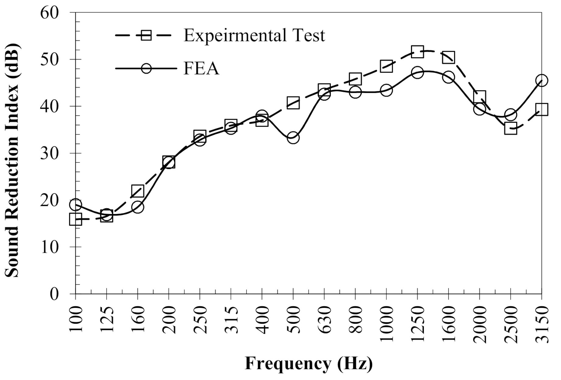
The finite element prediction model has been validated on a plasterboard wall featuring the C-channel stud as shown in Figure 2b. The validated prediction model was subsequently used to analyze the drywalls featuring perforated studs. The experimental measurements used for validation were tested in the acoustic transmission suite at the Sound Research Laboratory (SRL), UK. The numerically predicted R values in comparison to experimental test measurements observed for the non-perforated C-channel stud (P) is shown in Figure 4. Overall, the finite element prediction can be seen to closely follow the physical test curve at a frequency of 100–3150 Hz. Nevertheless, a 6 dB dip can be seen at 500 Hz for the FE model which was not found in experimentally measured data, indicating the likelihood of critical frequencies generally observed in harmonic analysis.
To identify the localized variation in the sound reduction index between the experimental and numerical results, a modal analysis of the same model was carried out. This aids in identifying the inherent resonant characteristics of the system in the forms of eigenmode frequencies. As such the analyses were carried out to identify all eigenmodes at the 1/3rd octave range. The results showed that at Eigenmodes 80 and 172, the natural frequencies of the wall were at 499.8 Hz and 1002.1 Hz, respectively. This indicates that the localized dip at 500 Hz and 1000 Hz are due to the influence of neighbouring critical frequencies of the numerical model.
Other than for the two frequencies 500 Hz and 1000 Hz, the differences between the curves were around 2.5 dB, which is consistent with accepted variation in measurement reproducibility for acoustic measurements [56]. Consequently, the sound reduction index at 1/3rd octave was used to compute the weighted index (), which is the single number quantity that is used to represent the acoustic insulation of the wall. The higher the weighted index the superior the acoustic insulation of the structure. Generally, the weighted index is accompanied with the spectrum adaptation terms and referring to the insulation against A-weighted pink noise and A-weighted urban traffic noise, respectively. For characterizing the acoustic insulation of a structure, the spectrum adaptation terms are important as they contextualize the performance based on different scenarios.
A-weighted pink noise defines the insulation of the wall against sound from activities such as high-speed train noise and cars travelling at speeds above 50 mph, in addition to medium and high-frequency noise from industrial activities. The term, on the other hand, characterizes performance at low to medium frequency sounds such as urban traffic, low-speed trains and machinery. Table 3 lists the between the finite element acoustic model and experimental measurement for the wall featuring the C-channel stud (P). The predicted and experimental single number ratings were found to be in excellent agreement, demonstrating that the numerical model is suitable for valid prediction of the sound reduction indices.
3.2. Influence of Perforated Studs on Sound Insulation
To identify the potential of the perforated studs, the sound reduction index was predicted using the validated finite element model. The sound insulation of each of the perforated stud configurations sandwiched between 15 mm plasterboard featuring air cavities was evaluated. Other than for the perforations all geometrical dimensions of the stud, wall and the model were kept constant. This means that the only difference between the different FE acoustic models is the perforated web configurations of the C-Channel stud.
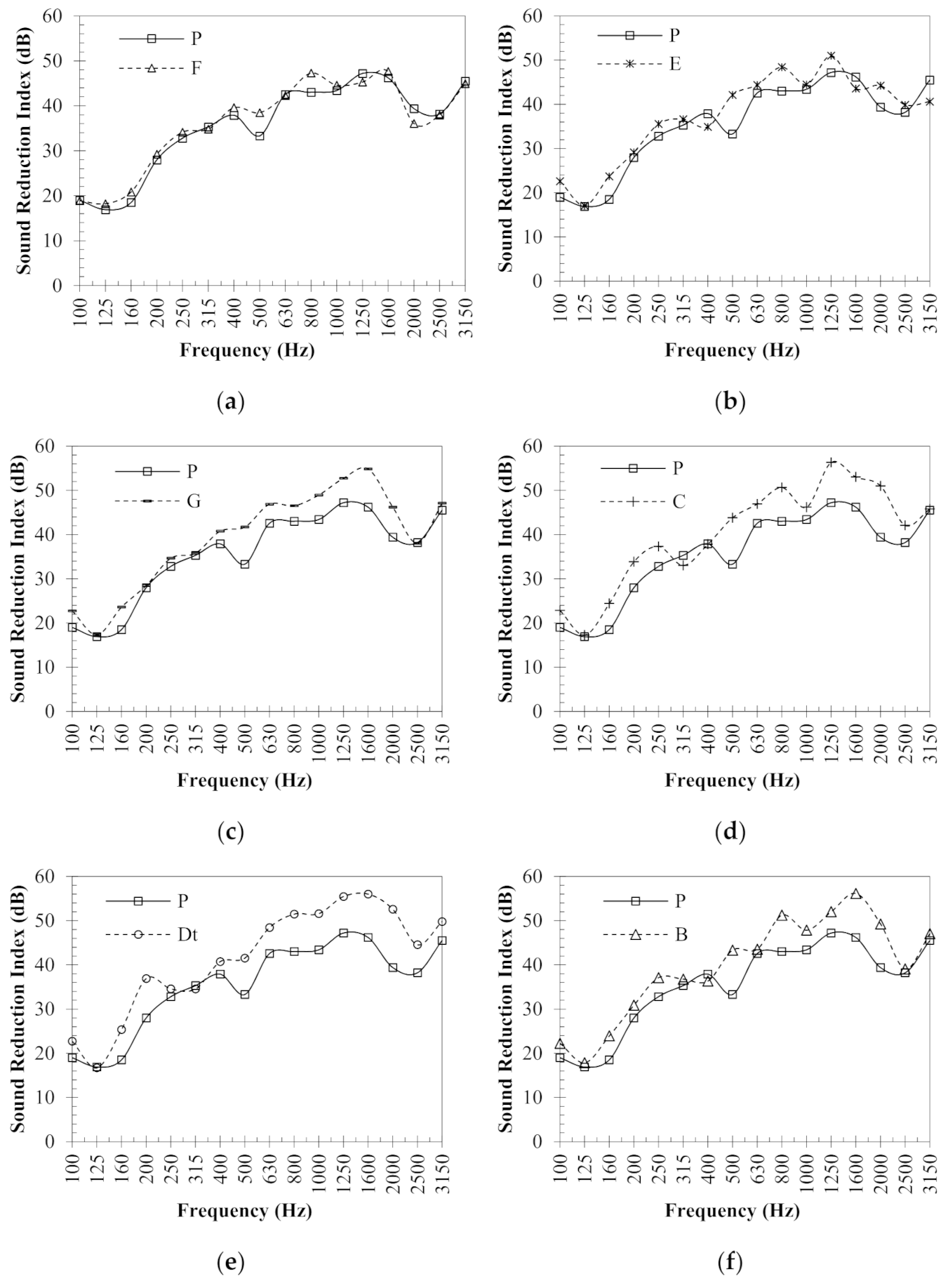
The airborne sound reduction index for all the different slot configurations at 1/3rd octaves are shown in Figure 5a–f. The results show that the acoustic performance of the wall is influenced by the perforated web. Despite having the perforated to the non-perforated area of the web constant for all the configurations, a difference in the sound reduction index can be seen depending upon the way the perforations are arranged on the web. It was observed that the perforation configuration Dt outperformed all other configurations other than for localized frequency effect observed at 125 Hz and 315 Hz.
For the overall sound insulation, the performance of Dt was closely followed by perforation configuration C. The performance of configuration-F was found to be the worst in comparison to the insulation demonstrated by all the other perforation configurations. Overall, the data show that both the placement and arrangement of perforations influences the acoustic response of the wall. The second-best insulation was demonstrated by the perforation configuration C, which may be favorable from an installation point of view as the performance is not dependent on the stud orientation.
Although the sound reduction index at 1/3rd octave provides a comprehensive description of the acoustic performance, when it comes to rating the sound insulation of the stud wall, the single number rating bears a higher significance. There are different single-number ratings featured in describing sound insulation of a building wall, out of which the method makes it more reliable and unambiguous for reporting the acoustic insulation using a single number that is directly proportional to the amount of sound transmission resisted by the partition.
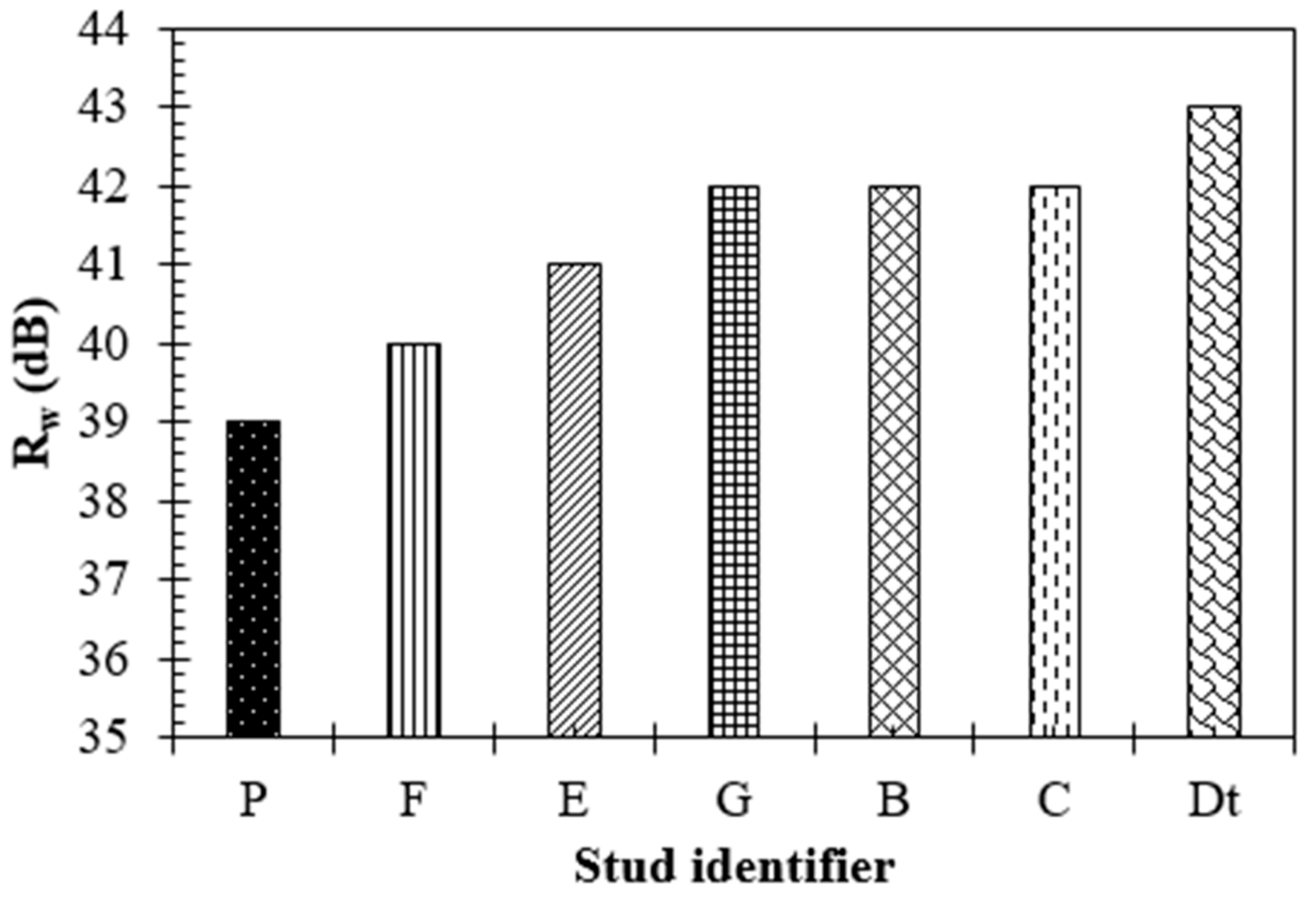
Figure 6 shows the weighted sound reduction index observed for the wall featuring different perforation configurations in comparison to the un-perforated stud. Comparing the , the plain stud P exhibited the lowest performance of all the designs tested. The perforated stud designs exhibit a slightly improved performance compared to the plain stud. The stud design Dt exhibited the best performance offering a +4 dB increase in insulation and F exhibited the lowest perforated stud performance with only a +1 dB increase compared to plain stud. Studs C, B and G exhibited similar performance with an improvement of +3 dB insulation. Stud E performed slightly better than F demonstrating an improvement of +2 dB in comparison to the non-perforated stud.
Comparing the , values, the perforated studs provide slightly superior acoustic insulation compared to a plain stud with similar dimensions. Although the perforation to non-perforation ratio was constant for the perforated configurations, the studs exhibited different performances depending on the location of perforation in the web. This shows that optimizing the perforation location is critical in achieving the best possible sound insulation for perforated studs. Although the overall trend is similar to what was observed when comparing the R values, the offers a clear differentiation in performance rating between the stud configurations allowing to identify the best performing design.
Comparing the acoustic performance of the perforated studs with that of literature; Hongisto et al. [57] experimentally evaluated the acoustic performance of perforated studs without observing notable improvements. This could be due to the requirement of a high perforation ratio to sufficiently lower the stiffness to influence the sound insulation. This is consistent with the observations of Wyngaert [58] where a high perforation ratio is called for to sufficiently lower the stud stiffness to influence the sound insulation. This study has also shown that the patterns and placement of perforations are also important parameters affecting the acoustic performance. Overall, the performance of the best performing perforated design in this study is consistent to that of inclined web perforations [58] which showed a gain of up to 3.8 dB in comparison to non-perforated studs. However, it is acknowledged that the experimental validation of the perforated stud designs is required before actual improvements can be characterized.
3.3. Correlation between Flexural Stiffness and Acoustic Response
Although the acoustic finite element model can be used to accurately predict the sound insulation offered by stud designs, the solution time is rather long. As such, an attempt to use a suitable structural parameter to offer an indication of the acoustic performance was sought. To identify the potential of using the stiffness of the stud as a suitable parameter in developing acoustic studs, the flexural stiffness at the flanges of the studs were evaluated using the finite element method.
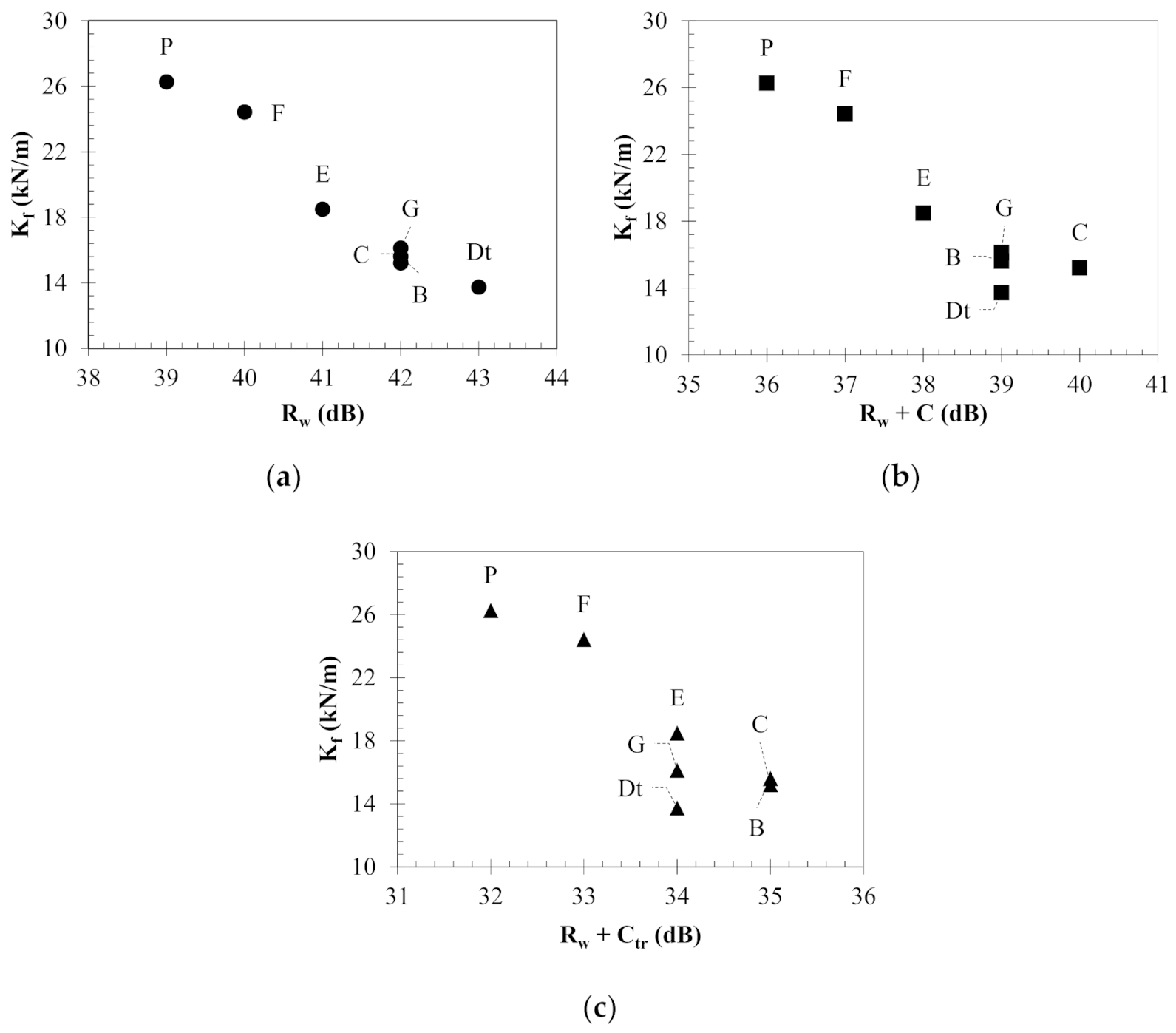
The highest was exhibited by the non-perforated stud (P) that showed the lowest acoustic insulation for all parameters tested, as shown in Figure 7. The perforated stud design that demonstrated the highest weighted sound reduction index exhibited the lowest flexural stiffness. Stud designs C and B exhibit comparatively close stiffness values resulting in of 42 (−2; −7) and 42 (−3; −7), respectively. The values for studs G and E were also gradually decreasing consistently with an increase in stiffness from 16.118 kN/m and 18.489 kN/m, respectively. However, when the spectrum adaptation terms were evaluated, C showed the highest insulation against A-weighted pink noise. Both perforation configurations C and B showed the highest insulation against A-weighted urban noise.
Based on the relationship between the stiffness and sound reduction index, it can be suggested that for the highest weighted sound reduction index, the perforations should be designed to reduce the stud’s flexural stiffness. For the current analysis, an overall improvement in sound insulation of +4 dB was observed when the flexural stiffness of the stud was almost halved. When it comes to the performance against A-weighted pink and urban noise, the flexural stiffness is not a reliable indicator, and the full numerical model should be considered. This is primarily due to the non-linear frequency weighting considered for the spectrum adaptation terms.
3.4. Structural Compliance
When modifying studs, it is critical to evaluate compliance with the relevant structural constraints. This was to ensure that the perforated studs meet the requirement to be used for non-load bearing partitions. The standard ISO5234 and ASTM C 754 requires that the deflection of the wall under a lateral load of 240 Pa must not exceed a lateral displacement ( ) of /240 where is the total length of the stud along with the height of the wall. This structural constraint was verified for all the perforated configurations to ensure compliance.
For each of the perforated slot configurations, the maximal allowed lateral deformation in the stud under a load of 240 Pa has been evaluated using the finite element method with the results as shown in Table 4. According to standards, the deflection of a non-load bearing wall under uniform lateral pressure of 240 Pa must not exceed /240 ( = 2900 mm). Comparing the results, it was found that all the stud designs were in compliance with all applications as the maximum deflection was 56% below the highest allowable deflection for grade SD which is severe duty as per ISO5234. Overall, the study shows that the developing perforated stud designs offer some potential in improving the acoustic insulation of drywall partition walls by reducing the acoustic bridging effect. However, it is acknowledged that experimental evaluation of the perforated stud designs are required before actual improvements can be quantified.
4. Conclusions
An acoustic numerical model suitable to predict the sound insulation of perforated stud walls has been developed. The analysis showed that the model is suitable for predicting the weighted sound reduction index and the spectrum adaptation terms describing the performance of the wall against both pink and urban noise. The validation showed that the acoustic model demonstrated in this study offered a ±1 dB accuracy in comparison to physical experiments. Modifying C-channel studs with various perforation configurations on the web was shown to be highly effective in reducing the acoustic bridging in conventional C-channel studs. Overall, six different perforation configurations were evaluated, namely: F, E, G, B, C and Dt, while keeping the web depth and gauge thickness constant. Improvements in the acoustic insulation rating for the wall were found to be up to +4 dB when using a perforation configuration of Dt. Furthermore, the frequency-dependent sound insulation at most of the frequencies improved, despite keeping the ratio of perforation to non-perforation area constant. This revealed that the perforation placement and arrangement is critical in improving the acoustic insulation of C-channel studs. Correlating the flexural stiffness of the studs with the weighted sound reduction indices revealed a consistent improvement in acoustic insulation as the stiffness reduced. Although reducing the flexural stiffness was shown to improve the sound reduction index, its dependency was inconsistent for the spectrum adaptation terms. Overall, despite the perforations, all the studs offered the necessary structural compliance as dictated by the relevant standards for a severe duty drywall partition.
Author Contributions
Conceptualization, Supervision, Methodology, Software, Investigation, Validation, Formal analysis, writing original draft, Writing—Reviewing and Editing: A.A., A.B. and J.R. All authors have read and agreed to the published version of the manuscript.
Funding
This research received no external funding.
Institutional Review Board Statement
Not applicable.
Informed Consent Statement
Not applicable.
Data Availability Statement
The data that support the findings of this study are available from the corresponding author upon reasonable request.
Conflicts of Interest
The authors declare no conflict of interest.
References
- Garg, N.; Kumar, A.; Maji, S. Significance and implications of airborne sound insulation criteria in building elements for traffic noise abatement. Appl. Acoust. 2013, 74, 1429–1435. [Google Scholar] [CrossRef]
- Hongisto, V.; Mäkilä, M.; Suokas, M. Satisfaction with sound insulation in residential dwellings—The effect of wall construction. Build. Environ. 2015, 85, 309–320. [Google Scholar] [CrossRef]
- Guillen, I.; Uris, A.; Estelles, H.; Llinares, J.; Llopis, A. On the sound insulation of masonry wall façades. Build. Environ. 2008, 43, 523–529. [Google Scholar] [CrossRef]
- Uris, A.; Maria Bravo, J.; Llinares, J.; Estelles, H. Influence of plastic electrical outlet boxes on sound insulation of gypsum board walls. Build. Environ. 2007, 42, 722–729. [Google Scholar] [CrossRef]
- Arjunan, A.; Baroutaji, A.; Praveen, A.S.; Olabi, A.G.; Wang, C.J. Acoustic performance of metallic foams. In Reference Module in Materials Science and Materials Engineering; Elsevier: Amsterdam, The Netherlands, 2019; ISBN 978-0-12-803581-8. [Google Scholar]
- Júnior, O.J.S.; Pinheiro, M.A.S.; Silva, J.J.R.; Pires, T.A.C.; Alencar, C.O.S. Sound insulation of gypsum block partitions: An analysis of single and double walls. J. Build. Eng. 2021, 39, 102253. [Google Scholar] [CrossRef]
- Li, X.; Mo, J.; Cai, H.; Liu, S.; Zhu, Z.; Jiang, Z.; Ma, Y. Optimal design and test study on sound insulation property of exterior wall enclosure of prefabricated substation. In Proceedings of the IOP Conference Series, Earth and Environmental Science, Shanghai, China, 7–9 August 2020; Volume 571. [Google Scholar]
- Novak, R.A. Sound insulation of lightweight double walls. Appl. Acoust. 1992, 37, 281–303. [Google Scholar] [CrossRef]
- Wang, J.; Lu, T.J.; Woodhouse, J.; Langley, R.S.; Evans, J. Sound transmission through lightweight double-leaf partitions: Theoretical modelling. J. Sound Vib. 2005, 286, 817–847. [Google Scholar] [CrossRef]
- Späh, M.; Weber, L. Flanking transmission of metal stud walls with different junction details. Appl. Acoust. 2016, 111, 86–95. [Google Scholar] [CrossRef]
- Umnova, O.; Tuev, D.; Giyasov, T. Design of low-rise buildings from thin-walled steel frame structures. MATEC Web Conf. 2018, 193, 3037. [Google Scholar] [CrossRef]
- Arjunan, A.; Wang, C.; English, M.; Stanford, M.; Lister, P. A computationally-efficient numerical model to characterize the noise behavior of metal-framed walls. Metals 2015, 5, 1414–1431. [Google Scholar] [CrossRef] [Green Version]
- Mak, C.M.; Wang, Z. Recent advances in building acoustics: An overview of prediction methods and their applications. Build. Environ. 2015, 91, 118–126. [Google Scholar] [CrossRef]
- Van den Wyngaert, J.C.E.; Schevenels, M.; Reynders, E.P.B. Shape optimization of studs in double-leaf plasterboard walls for maximal broadband sound insulation and minimal material use. Appl. Acoust. 2021, 183, 108307. [Google Scholar] [CrossRef]
- Narang, P.P. Transforming wall studs to slit resonator studs for improving sound insulation in walls. Appl. Acoust. 1994, 43, 81–90. [Google Scholar] [CrossRef]
- Isaac, C.W.; Pawelczyk, M.; Wrona, S. Comparative Study of Sound Transmission Losses of Sandwich Composite Double Panel Walls. Appl. Sci. 2020, 10, 1543. [Google Scholar] [CrossRef] [Green Version]
- Nowotny, Ł.; Nurzyński, J. The Influence of Insulating Layers on the Acoustic Performance of Lightweight Frame Floors Intended for Use in Residential Buildings. Energies 2020, 13, 1217. [Google Scholar] [CrossRef] [Green Version]
- Tadeu, A.; António, J.; Mateus, D. Sound insulation provided by single and double panel walls—a comparison of analytical solutions versus experimental results. Appl. Acoust. 2004, 65, 15–29. [Google Scholar] [CrossRef]
- Wareing, R.R.; Davy, J.L.; Pearse, J.R. Predicting the sound insulation of plywood panels when treated with decoupled mass loaded barriers. Appl. Acoust. 2015, 91, 64–72. [Google Scholar] [CrossRef]
- Yairi, M.; Koga, T.; Takebayashi, K.; Sakagami, K. Transmission of a spherical sound wave through a single-leaf wall: Mass law for spherical wave incidence. Appl. Acoust. 2014, 75, 67–71. [Google Scholar] [CrossRef] [Green Version]
- Poblet-Puig, J.; Rodríguez-Ferran, A.; Guigou-Carter, C.; Villot, M. The role of studs in the sound transmission of double walls. Acta Acust. United Acust. 2009, 95, 555–567. [Google Scholar] [CrossRef] [Green Version]
- Roozen, N.B.; Muellner, H.; Labelle, L.; Rychtáriková, M.; Glorieux, C. Influence of panel fastening on the acoustic performance of light-weight building elements: Study by sound transmission and laser scanning vibrometry. J. Sound Vib. 2015, 346, 100–116. [Google Scholar] [CrossRef] [Green Version]
- Vigran, T.E. Sound transmission in multilayered structures—Introducing finite structural connections in the transfer matrix method. Appl. Acoust. 2010, 71, 39–44. [Google Scholar] [CrossRef]
- Díaz-Cereceda, C.; Hetherington, J.; Poblet-Puig, J.; Rodríguez-Ferran, A. A deterministic model of impact noise transmission through structural connections based on modal analysis. J. Sound Vib. 2011, 330, 2801–2817. [Google Scholar] [CrossRef] [Green Version]
- Bradley, J.S.; Birta, J.A. A simple model of the sound insulation of gypsum board on resilient supports. Noise Control Eng. J. 2001, 49, 216–223. [Google Scholar] [CrossRef] [Green Version]
- Xu, Z.; Zhu, W.; Wang, J. Practical considerations on the sound insulation of gypsum board. In Proceedings of the INTER-NOISE and NOISE-CON Congress and Conference Proceedings, Beijing, China, 15 September 1987. [Google Scholar]
- Cambridge, J.E.; Davy, J.L.; Pearse, J. The Influence of the Wall Cavity on the Transmission Loss of Wall Systems—Experimental Trends. Build. Acoust. 2013, 20, 87–106. [Google Scholar] [CrossRef] [Green Version]
- Fausti, P.; Pompoli, R.; Smith, R.S. An Intercomparison of Laboratory Measurements of Airborne Sound Insulation of Lightweight Plasterboard Walls. Build. Acoust. 2016, 6, 127–140. [Google Scholar] [CrossRef]
- Smith, R.S.; Pompoli, R.; Fausti, P. An Investigation into the Reproducibility Values of the European Inter-Laboratory Test for Lightweight Walls. Build. Acoust. 2016, 6, 187–210. [Google Scholar] [CrossRef]
- Hwang, S.; Kim, J.; Lee, S.; Kwun, H. Prediction of sound reduction index of double sandwich panel. Appl. Acoust. 2015, 93, 44–50. [Google Scholar] [CrossRef]
- Piana, E.A. A method for determining the sound reduction index of precast panels based on point mobility measurements. Appl. Acoust. 2016, 110, 72–80. [Google Scholar] [CrossRef]
- Buzzi, T.; Courné, C.; Moulinier, A.; Tisseyre, A. Prediction of the sound reduction index: A modal approach. Appl. Acoust. 2003, 64, 793–814. [Google Scholar] [CrossRef]
- Pelton, H.L.; Carnes, T.N. 2 principles of acoustics and noise control for broadcast applications. In National Association of Broadcasters Engineering Handbook; Routledge: London, UK, 2007; pp. 419–454. ISBN 1136034102. [Google Scholar]
- Metzen, H.A. ISO ratings and descriptors for the built acoustical environment. In Handbook of Noise and Vibration Control; John Wiley & Sons: Hoboken, NJ, USA, 2007; pp. 1283–1296. ISBN 0471395994. [Google Scholar]
- Garg, N.; Kumar, A.; Maji, S. Practical Concerns Associated with Single-Number Ratings in Measuring Sound Transmission Loss Properties of Partition Panels. Arch. Acoust. 2013, 38, 115–124. [Google Scholar] [CrossRef] [Green Version]
- ISO. Acoustics—Rating of Sound Insulation in Buildings and of Building Elements. Part 1: Airborne Sound Insulation; ISO BS EN ISO 717-1:2020; ISO: Geneva, Switzerland.
- London, A. Transmission of Reverberant Sound through Double Walls. J. Acoust. Soc. Am. 1950, 22, 270–279. [Google Scholar] [CrossRef]
- Gerretsen, E. Predicting the sound reduction of building elements from material data. J. Acoust. Soc. Am. 1999, 105, 1200. [Google Scholar] [CrossRef]
- Van den Wyngaert, J.C.E.; Schevenels, M.; Reynders, E.P.B. Predicting the sound insulation of finite double-leaf walls with a flexible frame. Appl. Acoust. 2018, 141, 93–105. [Google Scholar] [CrossRef]
- Lin, G.; Garrelick, J.M. Sound transmission through periodically framed parallel plates. J. Acoust. Soc. Am. 1977, 61, 1014–1018. [Google Scholar] [CrossRef]
- Takahashi, D. Sound radiation from periodically connected double-plate structures. J. Sound Vib. 1983, 90, 541–557. [Google Scholar] [CrossRef]
- Skelton, E.A.; Broadbent, E.G. Acoustic scattering by parallel plates with periodic connectors. Proc. R. Soc. Lond. A Math. Phys. Sci. 1990, 427, 419–444. [Google Scholar] [CrossRef]
- Arjunan, A.; Wang, C.J.; Yahiaoui, K.; Mynors, D.J.; Morgan, T.; Nguyen, V.B.; English, M. Development of a 3D finite element acoustic model to predict the sound reduction index of stud based double-leaf walls. J. Sound Vib. 2014, 333, 6140–6155. [Google Scholar] [CrossRef]
- Yang, Y.; Mace, B.R.; Kingan, M.J. Wave and finite element method for predicting sound transmission through finite multi-layered structures with fluid layers. Comput. Struct. 2018, 204, 20–30. [Google Scholar] [CrossRef]
- Løvholt, F.; Norèn-Cosgriff, K.; Madshus, C.; Ellingsen, S.E. Simulating low frequency sound transmission through walls and windows by a two-way coupled fluid structure interaction model. J. Sound Vib. 2017, 396, 203–216. [Google Scholar] [CrossRef]
- Qiao, H.; He, Z.; Jiang, W.; Peng, W. Sound transmission of periodic composite structure lined with porous core: Rib-stiffened double panel case. J. Sound Vib. 2019, 440, 256–276. [Google Scholar] [CrossRef] [Green Version]
- Arjunan, A.; Wang, C.J.; Yahiaoui, K.; Mynors, D.J.; Morgan, T.; Nguyen, V.B.; English, M. Sound frequency dependent mesh modelling to simulate the acoustic insulation of stud based double-leaf walls. In Proceedings of the ISMA 2014—Conference on Noise and Vibration Engineering and USD 2014—International Conference on Uncertainty in Structural Dynamics, Leuven, Belgium, 15–17 September 2014. [Google Scholar]
- Ehrig, T.; Dannemann, M.; Luft, R.; Adams, C.; Modler, N.; Kostka, P. Sound Transmission Loss of a Sandwich Plate with Adjustable Core Layer Thickness. Materials 2020, 13, 4160. [Google Scholar] [CrossRef] [PubMed]
- ISO. ISO 10140-1:2021—Acoustics—Laboratory Measurement of Sound Insulation of Building Elements—Part 1: Application Rules for Specific Products. Available online: https://www.iso.org/standard/73910.html (accessed on 4 September 2021).
- BSI. Code of Practice. Internal Non-Loadbearing Partitioning; BSI BS 5234:1975; BSI: Singapore, 1975; p. 30. [Google Scholar]
- Kinsler, L.; Frey, A.R.; Coppens, A.; Sanders, J.V. Fundamental of Acoustics; John Wiley & Sons: New York, NY, USA, 2000; p. 548. [Google Scholar]
- Bathe, K.J. Finite Element Procedures; Pearson Education, Inc.: Watertown, MA, USA, 1996; ISBN 0133014584. [Google Scholar]
- Zienkiewicz, O.C.; Newton, R.E. Coupled vibrations of a structure submerged in a compressible fluid. In University of Wales, Swansea, Department of Civil Engineering, ISD, ISSC, Symposium on Finite Element Techniques at the Institut für Statik und Dynamik der luft- und Raumfahrtkonstruktionen; Report No. C/R/101/69; TUDelft: Stuttgart, Germany, 1969. [Google Scholar]
- ASTM. Standard Specification for Installation of Steel Framing Members to Receive Screw-Attached Gypsum Panel Products; ASTM C754-20; ASTM: West Conshohocken, PA, USA, 2020. [Google Scholar]
- Long, M. Fundamentals of acoustics. In Architectural Acoustics, 2nd ed.; Long, M., Ed.; Academic Press: Boston, MA, USA, 2014; pp. 39–79. ISBN 978-0-12-398258-2. [Google Scholar]
- Arjunan, A.; Baroutaji, A.; Latif, A. Acoustic behaviour of 3D printed titanium perforated panels. Results Eng. 2021, 11, 100252. [Google Scholar] [CrossRef]
- Hongisto, V.; Lindgren, M.; Helenius, R. Sound insulation of double walls—An experimental parametric study. Acta Acust. United Acust. 2002, 88, 904–923. [Google Scholar]
- Wyngaert, V. Den Numerical Prediction and Optimization of the Sound Insulation of Wall Systems; KU Leuven: Leuven, Belgium, 2020. [Google Scholar]
Figure 1.
Components of the finite element fluid-structure-interaction (FSI) acoustic model: (a) top view of the model showing the C-channel stud cross-section, (b) front view of the model showing the perforations on the web of the stud and (c) showing all components and the associated FSI; where components designated fluid are modeled with fluid elements while all others are modeled with solid structural elements. The figures are not drawn to scale to avoid skewing the stud shape due to the relatively large dimensions of the room.

Figure 2.
Components of the finite element structural model showing (a) the meshed stud and gypsum board assembly and (b) the cross-sectional geometry (all dimensions in mm) of the stud and the associated dimensions.
Figure 2.
Components of the finite element structural model showing (a) the meshed stud and gypsum board assembly and (b) the cross-sectional geometry (all dimensions in mm) of the stud and the associated dimensions.

Figure 3.
Different types of perforated and non-perforated stud configurations analyzed in this study showing (a) the perforation dimension and (b) the different perforation arrangements and labels.
Figure 3.
Different types of perforated and non-perforated stud configurations analyzed in this study showing (a) the perforation dimension and (b) the different perforation arrangements and labels.

Figure 4.
Sound reduction index observed between the finite element model and physical test data of a stud wall featuring a C-channel stud.
Figure 4.
Sound reduction index observed between the finite element model and physical test data of a stud wall featuring a C-channel stud.

Figure 5.
Sound reduction index at 1/3rd octave bands for different perforation configurations in comparison to non-perforated C-channel section designated P: (a) perforation-F; (b) perforation-E; (c) perforation-G; (d) perforation-C; (e) perforation-Dt; (f) perforation-B.
Figure 5.
Sound reduction index at 1/3rd octave bands for different perforation configurations in comparison to non-perforated C-channel section designated P: (a) perforation-F; (b) perforation-E; (c) perforation-G; (d) perforation-C; (e) perforation-Dt; (f) perforation-B.

Figure 6.
Weighted Sound reduction index of the wall with different perforated web designs (F, E, G, B, C and Dt) in comparison to the non-perforated C-channel stud P.
Figure 6.
Weighted Sound reduction index of the wall with different perforated web designs (F, E, G, B, C and Dt) in comparison to the non-perforated C-channel stud P.

Figure 7.
Correlation between flexural stiffness () at the stud flange and acoustic insulation of the study wall showing: (a) weighted sound reduction index; (b) A-weighted pink noise; (c) A-weighted urban traffic noise.
Figure 7.
Correlation between flexural stiffness () at the stud flange and acoustic insulation of the study wall showing: (a) weighted sound reduction index; (b) A-weighted pink noise; (c) A-weighted urban traffic noise.


Table 1.
Summary of the acoustic parameters for characterizing airborne sound insulation of buildings and of building elements.
Table 1.
Summary of the acoustic parameters for characterizing airborne sound insulation of buildings and of building elements.
| Parameter | Name | Context | Advantage | Consideration |
|---|---|---|---|---|
| Weighted sound reduction index | Airborne sound insulation rating in decibels of the reference curve at 500 Hz after shifting it in accordance with the method specified in ISO717-1 [36] | A single number allows for easy acoustic characterization | Performance below 100 Hz is not considered | |
| Weighted sound reduction index corresponding to pink noise | Value in decibels to be added to to take account of the characteristics of the pink noise spectra | Suitable to characterize insulation against living activities, children playing, railway traffic at medium and high speed, highway road traffic, jet aircraft, factories emitting medium to high frequency noise | Often adversely characterize lightweight construction such as dry walls | |
| Weighted sound reduction index corresponding to urban noise | Value in decibels to be added to to take account of the characteristics of the road traffic noise spectra | Suitable to characterize insulation against urban road traffic, low speed railway, aircraft, disco music, factories emitting low and medium frequency noise. | Emphasis is primarily towards low noise |
Table 2.
Material properties used for the numerical model.
| Material | E (GPa) | ||||
|---|---|---|---|---|---|
| Steel | 206 | 7929 | 0.31 | - | 0.25 |
| Gypsum | 2.5 | 848 | 0.25 | - | 0.1 |
| Mortar | 20 | 2000 | 0.17 | - | - |
| Acoustic fluid | - | 1.25 | - | 338 | - |
Table 3.
Weighted sound reduction indices showing the single number sound insulation rating for the stud wall between experimental and finite element evaluation.
Table 3.
Weighted sound reduction indices showing the single number sound insulation rating for the stud wall between experimental and finite element evaluation.
| Item | |||
|---|---|---|---|
| FEA | 39 | 36 | 31 |
| Experiment | 39 | 37 | 32 |
| Difference 1 | - | 1 dB | 1 dB |
1 For the sound reduction index the standard practice is to show the difference in decibels (dB) rather than in percentage (%).
Table 4.
Results of the structural compliance analysis showing the maximum deformation of the stud wall.
Table 4.
Results of the structural compliance analysis showing the maximum deformation of the stud wall.
| Stud Type | P | F | E | G | B | C | Dt |
|---|---|---|---|---|---|---|---|
| (mm) | 1.1 | 1.4 | 2.5 | 4.1 | 4.4 | 4.7 | 5.6 |
| /(/240) (%) | 9.10 | 11.59 | 20.69 | 33.93 | 36.41 | 38.90 | 46.34 |
Publisher’s Note: MDPI stays neutral with regard to jurisdictional claims in published maps and institutional affiliations. |
© 2021 by the authors. Licensee MDPI, Basel, Switzerland. This article is an open access article distributed under the terms and conditions of the Creative Commons Attribution (CC BY) license (https://creativecommons.org/licenses/by/4.0/).
Share and Cite
MDPI and ACS Style
Arjunan, A.; Baroutaji, A.; Robinson, J. Perforated Steel Stud to Improve the Acoustic Insulation of Drywall Partitions. Acoustics 2021, 3, 679-694. https://0-doi-org.brum.beds.ac.uk/10.3390/acoustics3040043
AMA Style
Arjunan A, Baroutaji A, Robinson J. Perforated Steel Stud to Improve the Acoustic Insulation of Drywall Partitions. Acoustics. 2021; 3(4):679-694. https://0-doi-org.brum.beds.ac.uk/10.3390/acoustics3040043
Chicago/Turabian StyleArjunan, Arun, Ahmad Baroutaji, and John Robinson. 2021. "Perforated Steel Stud to Improve the Acoustic Insulation of Drywall Partitions" Acoustics 3, no. 4: 679-694. https://0-doi-org.brum.beds.ac.uk/10.3390/acoustics3040043