
Design and Initial Evaluation of a Low-Cost Microprocessor-Controlled Above-Knee Prosthesis: A Case Report of 2 Patients


1
Metallurgical, Materials and Biomedical Engineering, The University of Texas at El Paso, El Paso, TX 79912, USA
2
Engineering Education & Leadership, The University of Texas at El Paso, El Paso, TX 79912, USA
*
Author to whom correspondence should be addressed.
Prosthesis 2022, 4(1), 60-72; https://0-doi-org.brum.beds.ac.uk/10.3390/prosthesis4010007
Submission received: 10 November 2021
/
Revised: 28 January 2022
/
Accepted: 8 February 2022
/
Published: 10 February 2022
(This article belongs to the Section Orthopedics and Rehabilitation)
Abstract
:For prosthesis users, knee units can range from simple devices costing $2000 up to $45,000 for high-end, microprocessor-controlled systems. These higher-end electronic knees provide significant advantages in stability, gait, and metabolic rate compared to their passive or mechanical counterparts. However, the high cost of such systems makes them inaccessible to most amputees. In this study, it was hypothesized that a microprocessor knee could be manufactured for less than $1000, with comparable stability and user experience to a high-end industry standard device. A prototype (E-Knee) was designed with a specific emphasis on stance stability, and was tested during patient gait trials. The gait trials used a repeated measures design to compare three knee devices (a simple passive knee, the prototype E-Knee, and a high-end knee). Ground reaction forces and a functionality questionnaire were used to compare devices. A microprocessor locking test was used to evaluate the prototype’s ability to prevent falls. Building on the LIMBS M3, a passive four-bar polycentric device, the E-Knee added sensing, computing, and controlling capabilities for a material cost of $507. Initial data from a two-subject trial served as proof-of-concept to validate the prototype and found that it improved gait by providing more stability than the M3 and had more gait-pattern similarities to the Ottobock C-Leg than to the M3. Patients reported no perceived differences in stability between the E-Knee and the C-Leg. Patient trials supported that the E-Knee prototype behaved more naturally than the low-end M3 device and had similar ground reaction forces to the C-Leg.
1. Introduction
Roughly 185,000 lower-limb amputations are performed in the United States each year, with above-knee amputations (AK) making up 26% (48,100) [1,2]. For patients looking to maintain their mobility, prosthetic legs offer normalcy and independence. While there are many types of prosthetic knee devices on the market, microprocessor-controlled prosthetic knees (MPKs) have been touted as greatly beneficial to amputee stability. With dynamic control of flexion and extension, such knees are preferred by 82% of active amputees [3]. Though some studies have found limited improvement, other studies have found that MPKs offer reduced hip work, decreased energy expenditure, increased gait stability, reduced risk for secondary injury, increased gait smoothness, and reduced falls [4,5,6,7,8,9,10,11].
Research has shown that MPKs are the best systems currently available for restoring normal gait and balance [12,13]. Gait symmetry in healthy subjects has been well defined by the literature [14,15], and microprocessor systems are designed to facilitate natural gait [16]. In studies, ground reaction forces (GRFs) are commonly used to compare and evaluate both gait symmetry, asymmetry, and limb performance. Due to repeatability and relatively low variance among subjects in similar circumstances, GRFs can be used to quantitatively compare performance between knee systems. Additionally, GRFs are used to study symmetry between intact and prosthetic limbs to determine gait normalcy [6].
Increased limb stability is one of the main advantages MPKs have over passive knees. The device’s ability to react automatically reduces stumbling and falling. Individuals with lower-limb amputations are at risk of injury during falls (40.7% prevalence rate); even with an MPK, at least half of prosthesis users fall annually [13,17].
While software and hardware can increase gait stability, as seen with MPKs, the geometric design of the knee also influences performance. These geometries fall into two primary categories: single-axis and polycentric. In single-axis systems, the knee rotates around a fixed point, which often calls for supplemental support to prevent knee hyperextension or collapse. Single-axis systems are common in MPKs due to their simplified design and linear flexion. In contrast, polycentric systems have moving centers of rotation and offer unique advantages over single-axis designs, such as increased stance stability and improved toe clearance [18,19,20]. The four-bar system is a common polycentric design and is often used for additional stance-phase stability.
The device designed in this study expands on the LIMBS M3 knee, a purely mechanical polycentric four-bar device. The M3 is designed, manufactured, and implemented by LIMBS International in the United States as a relief knee for low-income amputees throughout the world at a production cost of $20 [21]. In terms of commercial prostheses, the M3 is one of the most affordable options in contrast to higher-end MPKs, such as Ottobock’s C-Leg. These MPKs cost between $22,000 and $42,000 according to L-Codes, used in the United States for health insurance reimbursements. Even within developed economies, many without insurance would struggle to afford the repeated prosthetic costs for the benefits of an MPK. With approximately 25% of the global population earning under $1.25 each day [4], expensive MPKs are unaffordable to the majority of amputees. To address the current gap in the market, this study outlines the proof-of-concept and initial testing of an affordable MPK, which became labeled the electronic knee (E-Knee). The E-Knee prototype developed over the course of this study seeks to add computing components to the commercial LIMBS M3 knee discussed above.
It was hypothesized that the E-Knee could be manufactured at a cost less than $1000, with comparable gait and user experience to an industry standard high-end device. This would be determined by a 20% decrease in mean absolute error (MAE) of vertical GRFs between the M3 and E-Knee when compared to the patient’s MPK, and a less than 10% difference in survey responses between the E-Knee and the patient’s MPK.
2. Methods
The goal of the E-Knee was to serve as a proof-of-concept for a low-cost MPK with the ability to continuously monitor gait, adjust to gait variability, and catch subjects’ stumbling. As this research included the initial design of the system, the methodology is broken into the following segments: prototype design, study protocol, and data analysis.
2.1. Prototype Design
Due to the low-cost aim of this research, the fundamental building block for the design was the LIMBS M3 knee. To augment the knee, four potential methods of knee swing control were identified for the prototype: mechanical [22,23], pneumatic [19,24,25], hydraulic [5,16,19], and magnetorheological [5,26,27]. These methods were evaluated and compared to one another using a weighted decision matrix (Table 1). Due to its industry prevalence, a hydraulic method was chosen to be the benchmark. Except in the case of binary features, the control method scoring could vary between one and nine. Using each feature’s assigned weights, the product sum was calculated for each method. The results were normalized to make the final decision.
To guide the design of the prototype, the features from the decision matrix were aligned with design specifications commonly found in the literature and industry (Table 2). To reduce overall cost and increase the possibility for repair in developing economies, components were selected with an emphasis on off-the-shelf availability.
2.2. Study Protocol
To test the prototype, subjects were recruited through local prosthetists in El Paso, Texas. The study was approved and conducted according to Institutional Review Board (IRB) standards at The University of Texas at El Paso (IRB 868626-1). Patient-selection criteria included: (1) an activity level of K3 or higher; (2) no ongoing medical issues; (3) recommendation for the study by a prosthetist; and (4) primary prosthesis was an MPK. The subjects had standard fittings on their sockets, therefore, no component modifications were necessary. A prosthetist adjusted each device for the subjects to ensure they could walk comfortably and safely. The activity levels of the subjects were classified by the prosthetist using Medicare functional levels (K0–K4). These levels describe the subject’s ability to ambulate; levels K3 and K4 indicate the baseline ability to navigate environmental barriers and walk with variable speed [28].
Though mimicking an intact limb was the primary goal for the E-Knee, comparative data to industry standard high-end MPKs give relative milestones as well. For example, the C-Leg reduces falls (64%), reduces stumbles (59%), and increases balance (68%) compared to passive systems [28,29]. Therefore, the relative improvement of redesigning a passive knee can be evaluated through comparison.
Three different knees were used for the study: the LIMBS M3, the E-Knee prototype, and the patient’s current MPK. The study used the LIMBS M3 to evaluate the E-Knee’s improvements from a simpler design, and the current MPK for comparability to a familiar more advanced design. With each knee, subjects were asked to participate in the following study phases after a familiarization period: (1) Amputee Mobility Predictor survey (AMP), (2) walking trial, (3) microprocessor locking trial, and (4) LEGS Functional Parameters Questionnaire (LFPQ). During the walking and microprocessor locking trials, data were collected using a combination of two Bertec™ force plates and lower-limb infrared markers in a Northern Digital™ Investigator® 3D motion-capture system, sampling at 2000 Hz and 100 Hz, respectively. Infrared markers were placed on body segments and physical references, such as the greater trochanter, were digitized using mathematical relationships to the markers in a modified Helen Hayes configuration for the lower extremities. Visual 3D (C-Motion Inc., Germantown, MD, USA) was used to calculate joint angles.
Subjects would be asked to walk at their own speed for each sample, therefore, the GRF data were resampled into similar time segments using interpolation. The resulting curves were then averaged and the standard deviations found. This was done for the vertical and horizontal (fore/aft) data. Motion capture data were used to calculate the angle of the knee joint during gait. To measure fall prevention capabilities, it was necessary to compare knee flexion during the gait and locking trials. With the associated knee flexion datum during heel strike, knee angle was calculated at the point when the vertical GRF of the heel strike was at its maximum.
2.2.1. Amputee Mobility Predictor (AMP)
The AMP has been shown to quantify stability and mobility with a reliable level of certainty by using a summation of various scored tasks [28,30]. Subjects completed a shortened version of the AMP before the trials began. Focusing on metrics not measured by the trials, the AMP was abbreviated to the first thirteen questions. Recruited patients were already classified as mobile by prosthetists; thus, the abbreviated AMP was not used as a total indicator of mobility, but rather a comparison of relative mobility and stability between knee systems for each patient.
2.2.2. Walking Trial
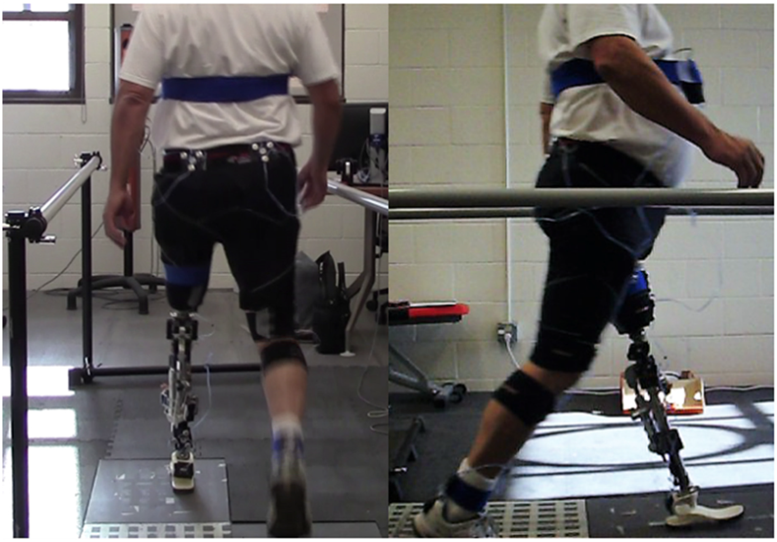
Subjects were asked to walk at a self-selected walking speed for 15 feet across the two force plates, one for each foot. Gait had commenced before the data-collection frame and continued past it to minimize gait acceleration and deceleration. Subjects were asked to repeat this procedure without rest periods until a total of five runs had been obtained for each knee. Although handrails were available in case of falling, the subjects walked unassisted. An example of this trial can be seen in Figure 1.
2.2.3. Microprocessor Locking Trial
Using the methodology described by Greene et al., the approximate Trochanter-Ankle (TA) line was determined and used with the instantaneous center of rotation to find the angle of instability for a polycentric knee system [20]. Using this procedure, the four-bar linkage of the LIMBS M3 is mechanically unstable at six degrees.
To test whether the E-Knee system could catch the subject in the event of a stumble, a physical block was inserted into the linkage to prevent extension past 10 degrees of flexion. At this slightly flexed angle, the mechanical characteristics of the four-bar mechanism were not supporting the weight of the subject. No adjustments were made to the control algorithms between this locking trial and the prior walking trial. Subjects were asked to take a single step onto the force plate while leading with the prototype. As before, data were collected for five runs.
2.2.4. LEGS Functional Parameters Questionnaire (LFPQ)
The LEGS (precursor to LIMBS) Functional Parameters Questionnaire (LFPQ) evaluates subject comfort, stability, and impression of a prosthesis using a continuous Likert scale [31]. In this study, subjects completed the LFPQ to assess their overall impression of the knee systems after each respective trial. The responses on the continuous Likert scales were converted into percentages by measuring the location of the subjects’ marks and dividing by the length of the scale.
3. Results
3.1. Prototype System
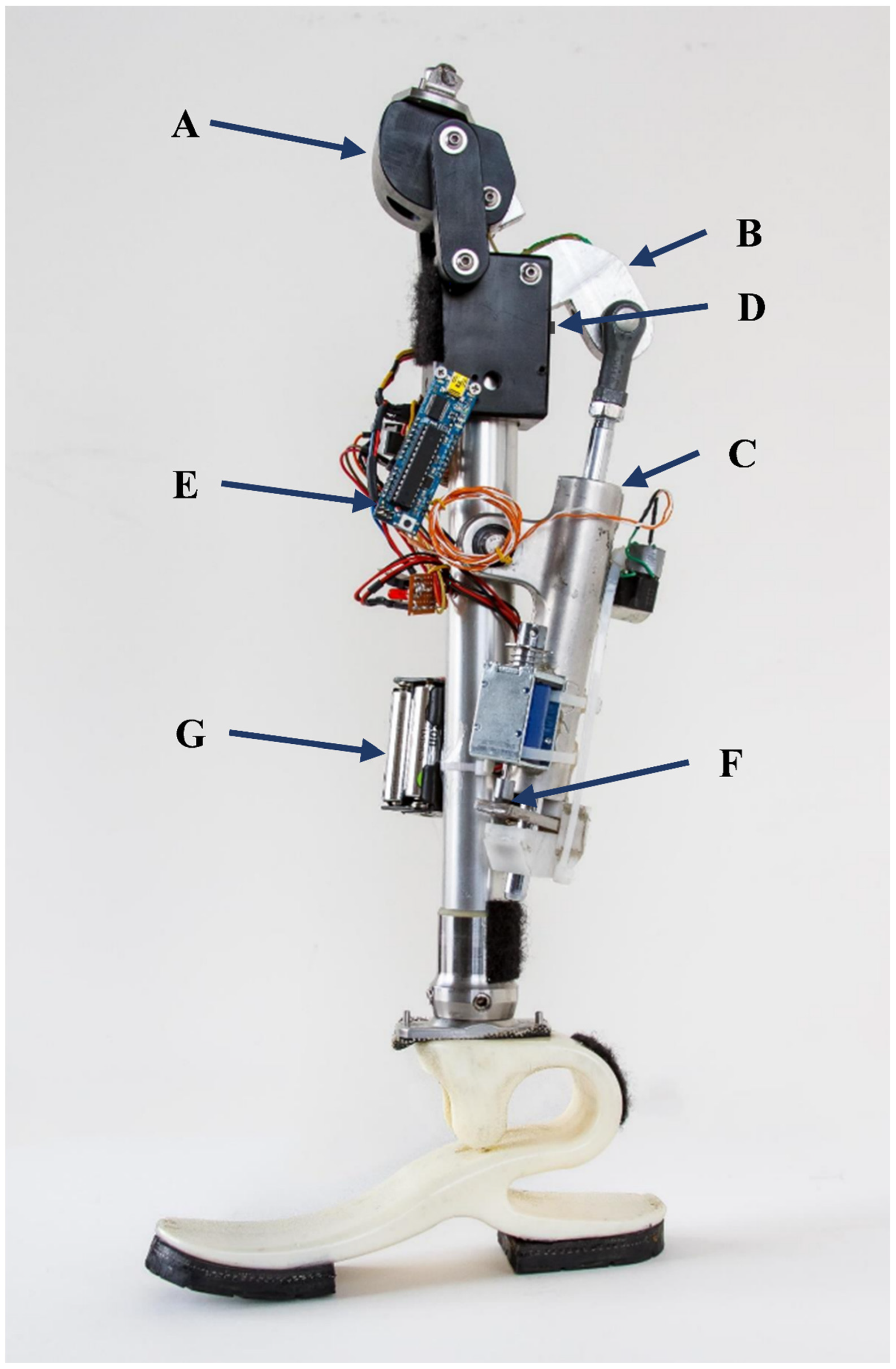
The final prototype E-Knee was composed of a modified LIMBS M3 (Figure 2A,B), a variable damper (Figure 2C), a magnetic sensor (Figure 2D), an Arduino microprocessor (Boarduino with ATmega 328; Figure 2E), a clamping mechanism (Figure 2F), and a power supply (Figure 2G). The M3 was modified by replacing the posterior link with an extended linkage that provided an anchoring point for the variable damper. Outside of mid-flexion, the angular change profile of total knee flexion matches closely to that of the posterior link. Therefore, dampening applied through this linkage during gait would be mostly linear.
The variable damper was originally a motorcycle steering stabilizer. It featured an hydraulic system with a normally open solenoid valve. Proportional to the voltage and current applied, the system restricts fluid flow. Note that the damper could not fully arrest flow and in this iteration of the design, the damper provided only passive dampening and a mounting point for the clamping mechanism. Active dampening is available and can be controlled through a transistor, but was not implemented for this study.
For the control system, the angular flexion of the knee was calculated using a Hall Effect sensor between the lower block of the knee and the modified posterior linkage. The overall knee angle was converted from the sensor readings with a logarithmic expression. An Arduino (Boarduino) was used as the control system and monitored the flexion at a resolution of 50 Hertz. The control program had three distinct states: stance, swing, and stumble. Using basic pattern recognition and thresholds of the monitored flexion velocity, the program switched between the gait states. If the program detected rapid angular flexion during stance, indicative of stumbling or collapse, the system switched to stumble and engaged the clamping mechanism, which would arrest flexion. The state would switch from stumble back to stance when knee extension was detected. If the angular flexion had a mild increase after stance, the state would be switched to swing. When knee extension velocity reached zero, swing state was always switched to stance, albeit briefly in case of collapse.
The clamping mechanism was designed to add the functionality of halting flexion. It was normally closed and used a 5V push-pull solenoid to change states. It attached to the rod of the damper and provided a mechanical binding to prevent further flexion.
The power supply consisted of eight AA batteries in series with a L7805CV voltage regulator. The 12V directly from the batteries could control the damper, and the 5 V after the voltage regulator had enough current to support the microcontroller, sensor, and solenoid.
In total, the E-Knee system components cost $507. The E-Knee features the electromechanical functionality of a typical MPK: stumble locking and variable gait cadence. However, its control system is basic. Knee pattern matching relies only on the knee angle and works primarily during gait. Stumble detection is only applied during the heel strike phase, and the variable dampening requires calibration data to be functional. Results according to the design specifications can be found in Table 3.
3.2. Quantitative Results
A total of two subjects participated in the study. Both subjects were confirmed healthy and capable walkers by their prosthetist. Subject 1 was male, 62 years old, 91.2 kg, a K3, and a unilateral transfemoral (left) amputee. Subject 2 was male, 70 years old, 112.5 kg, a K3, and a unilateral transfemoral (left) amputee.
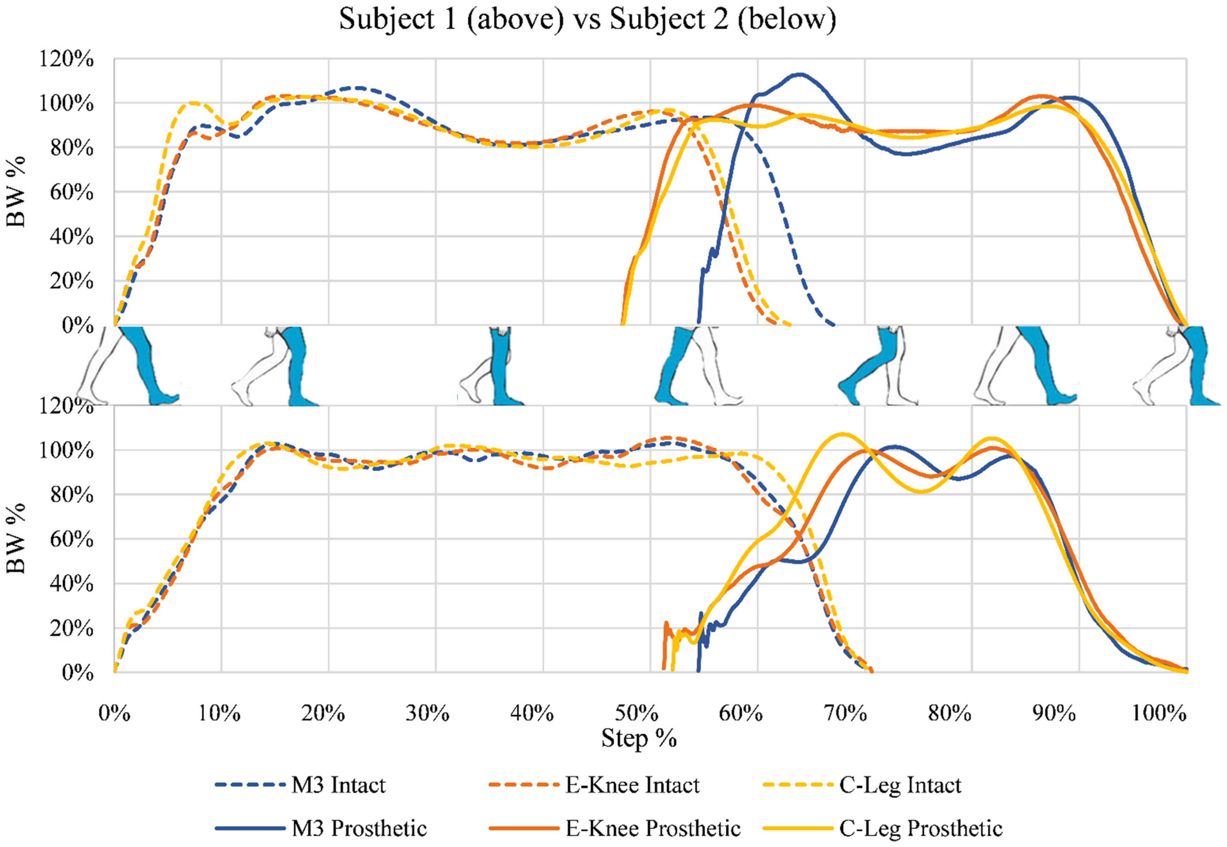
Subject 1 and Subject 2 used the C-Leg in their daily lives: versions 3 and 4, respectively. Both had no other medical conditions, and the amputations were results of earlier trauma. Figure 3 shows the results of the GRF during the walking trial. Body weight (BW) percentage was calculated using the measured GRF from a static sample before data collection with each knee. While the figure is shown in terms of step percentage, gait speeds were not equal between the different knee systems. For Subject 1, normalized gait speeds were C-Leg: 100%, E-Knee: 78.2%, and M3: 63.2% (C-Leg: 1.04 m/s, E-Knee: 0.82 m/s, and M3: 0.66 m/s). For Subject 2, normalized gait speeds were C-Leg: 100%, E-Knee: 78.3%, and M3: 81.1% (C-Leg: 0.51 m/s, E-Knee: 0.40 m/s, and M3: 0.41 m/s).
Table 4 shows the results by calculating the MAE of the vertical GRF between both the M3 and E-Knee when compared to the C-Leg. The final averaged decrease in MAE was 31.4%. Fore/aft GRF was examined to observe subject acceleration or deceleration during the trials. When considering a difference of greater than 20% to be significant, the Subjects 1 and 2′s fore/aft GRF decreased by 26.6% and 24.2%, respectively, during gait on the M3, but showed no significant difference for the E-Knee or C-Leg. Mediolateral GRF data were low in magnitude and showed no noteworthy differences between trials, knees, or subjects. Therefore, they are not considered in this analysis. Table 5 shows the results obtained from the kinematic data of the lower limbs and the vertical GRF during both the walking and microprocessor locking trial. The datapoint being considered is the maximum GRF during heel strike.
3.3. Qualitative Results
Results from the abbreviated AMP showed very little difference in the mobility between the knees, with scores among each subject being the same for both the C-Leg and E-Knee, and losing one point, due to balancing difficulty, on the M3.
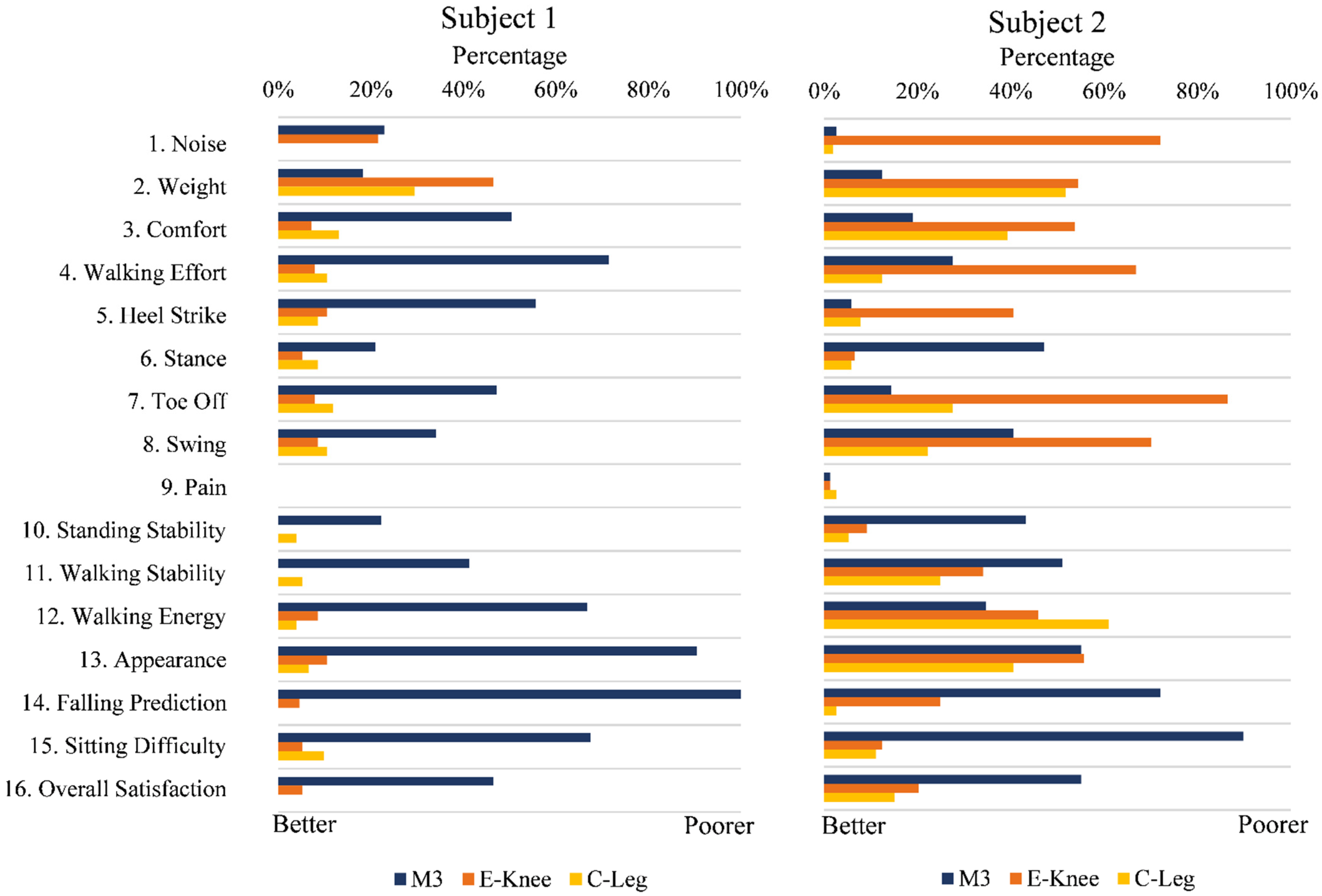
Full results of the LFPQ are given in Figure 4. According to the LFPQ, Subject 1 felt that the E-Knee was a considerable improvement over the M3. When ignoring noise and weight, the E-Knee differed from the C-Leg by a maximum of 6%. In contrast, the M3 differed from the C-Leg by a minimum of 12% and an average of 30% (excluding pain, which was 0 for all).
Data from Subject 2 are less conclusive. The E-Knee was superior to the M3 in questions of stability (Questions 6, 10, 11, 14), but the M3 was preferred for ease of gait (Questions 4, 5, 7, 8). When compared to the C-Leg, the E-Knee achieved the desired deviation (<10%) in questions 3, 6, 9, 10, 11, 15, and 16 (44% of questions).
4. Discussion
4.1. Prototype Functionality
The E-Knee prototype met the design specifications listed in Table 2, as shown in Table 3. Demonstrated by the microprocessor locking test (Table 5), the clamping mechanism was able to prevent collapse. With the physical blockage keeping the knee at a minimum of 10 degrees of flexion during this trial, the results of Subject 2 suggest that full extension was not happening during gait. This could be due to improper segment calibration in Visual 3D or an angle inclination in the alignment of the prosthetic system. Nevertheless, the system supported a subject of 112.5 kg, which was beyond the initial goal of 80 kg. Further work would involve the ISO 10328 principal load testing, but also a more thorough analysis of the clamping mechanism’s locking capabilities throughout flexion. In terms of component costs, the prototype’s $507 valuation does not consider manufacturing and production costs and should be kept in mind when comparing to commercial prices for other devices.
Mechanically, the E-Knee functioned similarly to the M3 during normal gait. As demonstrated by the microprocessor locking trial, the E-Knee can react to stumbles and prevent falls. It should be noted that the E-Knee control algorithms were not altered between the walking and microprocessor locking trials, demonstrating a control system capable of preventing knee collapse in the case of stumbles.
Another limitation of the control algorithm is the lack of variability in dampening. In this prototype version, the damper provides passive damping and an attachment point for the clamping mechanism. The electronic controls allowed the damper to provide enough dampening to severely slow down flexion under load, but the damper did not function in this capacity during the trials. Future work will include the development of a variable dampening control system that adapts to patient gait speed.
Limitations of the design include a maximum knee flexion of 90 degrees, low resolution on the knee flexion sensor, and state-programmed stumble detection. Future work for the knee flexion restriction would most likely include a linkage that modifies the bottom block and contains a custom hydraulic unit. Such a unit should accomplish the tasks of dampening and arresting flexion. Furthermore, the current state program was limited, and was primarily used to showcase the mechanical viability of the system. As the sensor system relied on a Hall Effect sensor with a non-linear measurement, the resolution of the system was greater during lower flexion angles. This limitation introduced greater noise during flexion, and limited the precision of the gait phase switching algorithm. It used rudimentary triggers to switch between gait and locking, and should, in the future, include more advanced gait recognition and further ambulation states.
4.2. Experimental Data
When examining MAE between the knees on the graphs shown in Figure 3, the E-Knee emulated the C-Leg more closely than it emulated the M3 (Table 4). Though the MAE improvement from the M3 to the E-Knee varied between subjects, both showed marked improvement and the average improvement was 31.4%, firmly above the hypothesized 20%.
Subject walking speed and the proportion of time spent on the intact limb versus the prosthetic limb are indicative of subject trust in the prosthetic device [3]. It is, therefore, indicated that both subjects trusted the M3 the least, with almost equal times spent on the C-Leg and E-Knee. Though by this metric, it should also be noted that subject 2 distrusted all prosthetic knees more than subject 1. Subject 1′s difference between intact and prosthetic duration is 10% for both the E-Knee and C-Leg, while Subject 2′s difference is 21%. While self-selected speeds allowed for intra-prosthesis comparison, future work should include set gait speed to draw further conclusions between subject’s GRFs.
Although the classified activity levels of both subjects (K3) indicated good health and vigor, younger subjects and additional activity levels would help diversify data and strengthen conclusions. Nevertheless, according to a study by Batten et al., Subject 1 and 2′s C-Leg speed data indicate activity levels of K4 and K3, respectively [33].
Subjects 1 and 2 slowed down by 26.6% and 24.2%, respectively, during their M3 walking trials. A reason for this could be the limited walking area available. Future work should include either longer walking stretches or an instrumented treadmill so that gait speed would be more constant. Additionally, a treadmill would allow for longer stretches of data collection, reducing the likelihood of sensor obstruction. Though data appeared continuous at the time of collection, the motion capture data were ultimately only useful for the knee angle during heel strike. This was due to clothing, limb, and safety rail obstructions of the physical markers beyond the capacity of interpolation.
It should be noted that the M3 and E-Knee trials were conducted with a first-generation Niagara Foot. During the C-Leg trial, the subjects wore their regular feet. Comparative data between the feet were not considered at the time of the trial, and this would have some effect on the GRFs. Additionally, the subjects were given an acclimation period with the M3 and the E-Knee of 20 min while the prosthetist ensured they were walking properly. Such a short window of adaption is a severe limitation, but it was not feasible to use the E-Knee in all contexts. To give context and comparison, the M3 was also acclimated for the same window. Results could improve significantly if the subjects had longer to adapt. Other studies have speculated that an increased acclimation period increased the efficacy of MPK systems [12].
4.3. Subject Response
Application of the AMP was used to measure relative mobility between the different knees, not full subject mobility. As stated in the results, there were no significant differences between the knee systems, which shows that in relative terms, all knees were equally mobile. Both subjects struggled more with balancing on the M3, which can be expected with a passive knee.
As mentioned previously, Subject 2 exhibited signs of prosthesis distrust and possible knee flexion during gait. Both indicate that Subject 2′s gait is less than ideal. Qualitatively, the E-Knee was shown to be very comparable to the C-Leg with Subject 1; and more stable than the M3 with Subject 2.
5. Conclusions
The results of this study support the hypothesis that a prototype microprocessor knee can be manufactured at less than $1000 with comparable stability and user experience to a standard high-end device. Preliminary testing suggests that the E-Knee improves the passive M3 knee and performs more similarly to the Ottobock C-Leg during gait. Though the E-Knee has reduced functionality from commercial MPKs, it quantitatively and qualitatively demonstrated a tendency toward similar stability of the C-Leg while its components cost 2.4% of the C-Leg’s commercial price.
Author Contributions
Conceptualization, L.G. and R.V.G.; methodology, L.G. and R.V.G.; software, L.G.; validation, L.G.; formal analysis, L.G.; investigation, L.G.; resources, R.V.G.; data curation, L.G.; writing—original draft preparation, L.G.; writing—review and editing, L.G. and R.V.G.; visualization, L.G.; supervision, R.V.G.; project administration, R.V.G.; funding acquisition, L.G. and R.V.G. All authors have read and agreed to the published version of the manuscript.
Funding
This research received no external funding.
Institutional Review Board Statement
The study was conducted according to the guidelines of the Declaration of Helsinki, and approved by the Institutional Review Board of The University of Texas at El Paso (868626-1, 7 March 2016).
Informed Consent Statement
Informed consent was obtained from all subjects involved in the study.
Data Availability Statement
The data presented in this study are available on request from the corresponding author.
Acknowledgments
Thank you to Gina Galey for her edits; undergraduate lab assistant, Natalia Acosta, for her assistance; prosthetist, Nina Weisenbacher, for patient fitting; and the Anita Mochen Loya Innovation Fund in Engineering for internal funding.
Conflicts of Interest
The authors declare no conflict of interest. The funders had no role in the design of the study; in the collection, analyses, or interpretation of data; in the writing of the manuscript, or in the decision to publish the results.
References
- Amputee Coalition. Amputee Statistics You Ought to Know. 2012. Available online: http://www.advancedamputees.com/amputee-statistics-you-ought-know (accessed on 3 February 2020).
- Dillingham, T.R.; Pezzin, L.E.; MacKenzie, E.J. Limb Amputation and Limb Deficiency: Epidemiology and Recent Trends in the United States. South. Med. J. 2002, 95, 875–883. [Google Scholar] [CrossRef] [PubMed]
- Hafner, B.J.; Willingham, L.L.; Buell, N.C.; Allyn, K.J.; Smith, D.G. Evaluation of Function, Performance, and Preference as Transfemoral Amputees Transition from Mechanical to Microprocessor Control of the Prosthetic Knee. Arch. Phys. Med. Rehabil. 2007, 88, 207–217. [Google Scholar] [CrossRef] [PubMed]
- Chen, S.; Ravallion, M. China Is Poorer Than We Thought, but No Less Successful in the Fight against Poverty; World Bank Publications: Herndon, VA, USA, 2010; pp. 327–340. [Google Scholar] [CrossRef] [Green Version]
- Johansson, J.L.; Sherrill, D.M.; Riley, P.O.; Bonato, P.; Herr, H. A Clinical Comparison of Variable-Damping and Mechanically Passive Prosthetic Knee Devices. Am. J. Phys. Med. Rehabil. 2005, 84, 563–575. [Google Scholar] [CrossRef]
- Gailey, R. Review of secondary physical conditions associated with lower-limb amputation and long-term prosthesis use. J. Rehabil. Res. Dev. 2008, 45, 15–30. [Google Scholar] [CrossRef]
- Martinez-Villalpando, E.C.; Herr, H. Agonist-antagonist active knee prosthesis: A preliminary study in level-ground walking. J. Rehabil. Res. Dev. 2009, 46, 361–373. [Google Scholar] [CrossRef] [PubMed]
- Theeven, P.J.; Hemmen, B.; Brink, P.R.; Smeets, R.J.; Seelen, H.A. Measures and procedures utilized to determine the added value of microprocessor-controlled prosthetic knee joints: A systematic review. BMC Musculoskelet. Disord. 2013, 14, 333. [Google Scholar] [CrossRef] [Green Version]
- Hafner, B.J.; Smith, D.G. Differences in function and safety between Medicare Functional Classification Level-2 and -3 transfemoral amputees and influence of prosthetic knee joint control. J. Rehabil. Res. Dev. 2009, 46, 417–433. [Google Scholar] [CrossRef]
- Prinsen, E.; Nederhand, M.; Sveinsdóttir, H.; Prins, M.; van der Meer, F.; Koopman, H.; Rietman, J. The influence of a user-adaptive prosthetic knee across varying walking speeds: A randomized cross-over trial. Gait Posture 2017, 51, 254–260. [Google Scholar] [CrossRef]
- Highsmith, M.J.; Kahle, J.T.; Shepard, N.T.; Kaufman, K.R. The effect of the c-leg knee prosthesis on sensory dependency and falls during sensory organization testing. Technol. Innov. 2014, 15, 343–347. [Google Scholar] [CrossRef]
- Kaufman, K.; Levine, J.; Brey, R.; Iverson, B.; McCrady, S.; Padgett, D.; Joyner, M. Gait and balance of transfemoral amputees using passive mechanical and microprocessor-controlled prosthetic knees. Gait Posture 2007, 26, 489–493. [Google Scholar] [CrossRef]
- Hahn, A.; Lang, M. Effects of Mobility Grade, Age, and Etiology on Functional Benefit and Safety of Subjects Evaluated in more than 1200 C-Leg Trial Fittings in Germany. JPO J. Prosthet. Orthot. 2015, 27, 86–94. [Google Scholar] [CrossRef]
- Giakas, G.; Baltzopoulos, V. Time and frequency domain analysis of ground reaction forces during walking: An investigation of variability and symmetry. Gait Posture 1997, 5, 189–197. [Google Scholar] [CrossRef]
- Chao, E.; Laughman, R.; Schneider, E.; Stauffer, R. Normative data of knee joint motion and ground reaction forces in adult level walking. J. Biomech. 1983, 16, 219–233. [Google Scholar] [CrossRef]
- Bellmann, M.; Schmalz, T.; Blumentritt, S. Comparative Biomechanical Analysis of Current Microprocessor-Controlled Prosthetic Knee Joints. Arch. Phys. Med. Rehabil. 2010, 91, 644–652. [Google Scholar] [CrossRef] [PubMed]
- Miller, W.C.; Deathe, A.; Speechley, M.; Koval, J. The influence of falling, fear of falling, and balance confidence on prosthetic mobility and social activity among individuals with a lower extremity amputation. Arch. Phys. Med. Rehabil. 2001, 82, 1238–1244. [Google Scholar] [CrossRef]
- Gard, S.A.; Childress, D.S.; Uellendahl, J.E. The Influence of Four-Bar Linkage Knees on Prosthetic Swing-Phase Floor Clearance. JPO J. Prosthet. Orthot. 1996, 8, 34–40. [Google Scholar] [CrossRef]
- Tang, P.C.; Ravji, K.; Key, J.J.; Mahler, D.B.; Blume, P.A.; Sumpio, B. Let Them Walk! Current Prosthesis Options for Leg and Foot Amputees. J. Am. Coll. Surg. 2008, 206, 548–560. [Google Scholar] [CrossRef]
- Greene, M.P. Four Bar Linkage Knee Analysis. J. Prosthet. Orthot. 1983, 37, 15–24. [Google Scholar]
- Rispin, K.; Husk, C.; Lew, S.; Schufeldt, T.; Gonzalez, R. Functional comparison of the legs M1 knee to commonly available developing world alternatives. In Proceedings of the 13th World Congress of the International Society for Prosthetics and Orthotics, Leipzig, Germany, 10–15 May 2010; Volume 391, pp. 724–725. [Google Scholar]
- Sup, F.; Varol, H.A.; Mitchell, J.; Withrow, T.; Goldfarb, M. Design and control of an active electrical knee and ankle prosthesis. In Proceedings of the 2nd Biennial IEEE/RAS-EMBS International Conference on Biomedical Robotics and Biomechatronics, Scottsdale, AZ, USA, 19–22 October 2008; Volume 2008, pp. 523–528. [Google Scholar] [CrossRef] [Green Version]
- Kaufman, K.R.; Levine, J.A.; Brey, R.H.; McCrady, S.K.; Padgett, D.J.; Joyner, M.J. Energy Expenditure and Activity of Transfemoral Amputees Using Mechanical and Microprocessor-Controlled Prosthetic Knees. Arch. Phys. Med. Rehabil. 2008, 89, 1380–1385. [Google Scholar] [CrossRef] [Green Version]
- Sup, F.; Bohara, A.; Goldfarb, M. Design and Control of a Powered Transfemoral Prosthesis. Int. J. Robot. Res. 2008, 27, 263–273. [Google Scholar] [CrossRef] [Green Version]
- Radcliffe, C.W.; Lamoreux, L. Uc-Bl Pneumatic Swing-Control Unit for Above-Knee Prostheses. Bulletin of Prosthetics Research-Fall. 1968; pp. 73–89. Available online: http://www.rehab.research.va.gov/jour/68/5/2/73.pdf (accessed on 15 February 2015).
- Herr, H.; Wilkenfeld, A. User-adaptive control of a magnetorheological prosthetic knee. Ind. Robot. Int. J. Robot. Res. Appl. 2003, 30, 42–55. [Google Scholar] [CrossRef] [Green Version]
- Ochoa-Diaz, C.; Rocha, T.S.; Oliveira, L.D.L.; Paredes, M.G.; Lima, R.; Bo, A.P.L.; Borges, G.A. An above-knee prosthesis with magnetorheological variable-damping. In Proceedings of the 5th IEEE RAS/EMBS International Conference on Biomedical Robotics and Biomechatronics, Sao Paulo, Brazil, 12–15 August 2014; pp. 108–113. [Google Scholar] [CrossRef]
- Highsmith, M.J.; Kahle, J.T.; Bongiorni, D.R.; Sutton, B.S.; Groer, S.; Kaufman, K. Safety, Energy Efficiency, and Cost Efficacy of the C-Leg for Transfemoral Amputees. Prosthet. Orthot. Int. 2010, 34, 362–377. [Google Scholar] [CrossRef] [PubMed] [Green Version]
- Gailey, R.S.; Roach, K.E.; Applegate, E.B.; Cho, B.; Cunniffe, B.; Licht, S.; Maguire, M.; Nash, M.S. The Amputee Mobility Predictor: An instrument to assess determinants of the lower-limb amputee’s ability to ambulate. Arch. Phys. Med. Rehabil. 2002, 83, 613–627. [Google Scholar] [CrossRef] [PubMed] [Green Version]
- Wurdeman, S.R.; Myers, S.; Jacobsen, A.L.; Stergiou, N. Adaptation and Prosthesis Effects on Stride-to-Stride Fluctuations in Amputee Gait. PLoS ONE 2014, 9, e100125. [Google Scholar] [CrossRef]
- Rispin, K.; Schlung, J.; Gonzalez, R.; Engineering, B.; Ayers, S. Preliminary Validation of the LEGS Functional Parameters Questionnaire; Rehabilitation Engineering Society of North America: Arlington, VA, USA, 2011. [Google Scholar]
- Pirker, W.; Katzenschlager, R. Gait disorders in adults and the elderly: A clinical guide. Wien. Klin. Wochenschr. 2016, 129, 81–95. [Google Scholar] [CrossRef] [Green Version]
- Batten, H.R.; McPhail, S.; Mandrusiak, A.M.; Varghese, P.N.; Kuys, S.S. Gait speed as an indicator of prosthetic walking potential following lower limb amputation. Prosthet. Orthot. Int. 2018, 43, 196–203. [Google Scholar] [CrossRef] [Green Version]
Figure 1.
Subject 1 during walking trial on E-Knee. Posterior (left) and sagittal (right) views.

Figure 2.
Fully assembled prototype. Knee is flexed and Niagara foot is attached. Photo curtesy of Aaron Nystrom. Components: LIMBS M3 (A), modified back link (B), variable damper (C), magnetic sensor (D), Arduino microprocessor (E), clamping mechanism (F), and power supply (G).
Figure 2.
Fully assembled prototype. Knee is flexed and Niagara foot is attached. Photo curtesy of Aaron Nystrom. Components: LIMBS M3 (A), modified back link (B), variable damper (C), magnetic sensor (D), Arduino microprocessor (E), clamping mechanism (F), and power supply (G).

Figure 3.
Subjects 1 and 2′s vertical GRFs for each prosthesis in the walking trial (top and bottom). Shown in two parts: the intact stance (dashed), and the prosthetic stance (solid). Given in body weight percentage (BW %) over one step (time from intact heel strike to prosthesis toe off). Standard deviations for Subject 1 and Subject 2 within datasets averaged to 3.43% and 5.10%, respectively. Step phase figures adapted from Pirker et al. [32].

Figure 4.
LFPQ responses for M3, E-Knee, and C-Leg for both Subject 1 (left) and Subject 2 (right). Responses recorded along a line are represented as percentages of the whole line length; increase in percentage represents poorer outcome.
Figure 4.
LFPQ responses for M3, E-Knee, and C-Leg for both Subject 1 (left) and Subject 2 (right). Responses recorded along a line are represented as percentages of the whole line length; increase in percentage represents poorer outcome.


Table 1.
Control method decision matrix for common features found in literature across four candidate control methods. Each control method is scored per feature on either a one to nine scale or binary (yes or no) flag. Results were normalized to the highest scoring method for intuitive comparison.
Table 1.
Control method decision matrix for common features found in literature across four candidate control methods. Each control method is scored per feature on either a one to nine scale or binary (yes or no) flag. Results were normalized to the highest scoring method for intuitive comparison.
| Feature | Weight (1–10) | Hydraulic | Pneumatic | Magnetorheological | Mechanical |
|---|---|---|---|---|---|
| Stability | 10 | 5 | 4 | 5 | 5 |
| Weight Limit | 9 | 5 | 3 | 4 | 2 |
| Maintenance ease | 9 | 5 | 4 | 2 | 6 |
| Cost | 8 | 5 | 7 | 2 | 6 |
| Variable Cadence (binary) | 8 | 1 | 1 | 1 | 1 |
| Immediate support on first step of stairs (binary) | 6 | 1 | 0 | 1 | 1 |
| Supportive yield for sitting down (binary) | 6 | 1 | 1 | 1 | 1 |
| Knee locking (binary) | 6 | 1 | 1 | 1 | 1 |
| Redesign amount | 5 | 5 | 5 | 5 | 3 |
| Degree of Flexion | 5 | 5 | 5 | 7 | 7 |
| Weight | 3 | 5 | 6 | 4 | 5 |
| Final Results | 271 | 247 | 218 | 261 | |
| Normalized | 100 | 91 | 80 | 96 |
Table 2.
Design features based on literature review and field requirements versus prototype design specifications.
Table 2.
Design features based on literature review and field requirements versus prototype design specifications.
| Feature | Specification |
|---|---|
| Stability | Provide mechanism to arrest flexion. |
| Weight Limit | Support patient of 80 kg. |
| Maintenance ease | Use retail parts commonly available. |
| Cost | Cost less than $1000. |
| Variable cadence | Include mechanism for variable swing control. |
| Immediate support on first step of stairs | Must be able to detect step. |
| Supportive yield for sitting down | Include mechanism for variable knee resistance. |
| Knee locking | Must have immediate effect from stability mechanism. |
| Redesign amount | Minimally redesign M3 knee. |
| Degree of flexion | Minimum 90 degrees of flexion. |
| Weight | Weigh less than 2.27 kg (5 lb). |
Table 3.
Design specifications vs. results of E-Knee.
| Specification | Result |
|---|---|
| Provide mechanism to arrest flexion | Clamping Mechanism |
| Support patient of 80 kg | Walking test of 112.5 kg |
| Use retail parts commonly available | No custom components |
| Cost less than $1000 | Retail component cost of $507.23 |
| Include mechanism for variable swing control | Variable Damper |
| Must be able to detect step | Hall Effect Sensor for angle. Microprocessor extrapolates step conditions |
| Include mechanism for variable knee resistance | Variable Damper |
| Must have immediate effect from stability mechanism | 20 ms microprocessor response resolution |
| Minimally redesign M3 knee | Only back link redesigned |
| Minimum 90 degrees of flexion | 90 degrees of flexion |
| Weigh less than 2.27 kg (5 lb) | 1.97 kg (4.34 lb) |
Table 4.
Mean absolute error (MAE) of vertical GRF when compared to the C-Leg. Percent decrease highlights improvement from M3 to E-Knee.
Table 4.
Mean absolute error (MAE) of vertical GRF when compared to the C-Leg. Percent decrease highlights improvement from M3 to E-Knee.
| Subject 1 | Subject 2 | Average | |
|---|---|---|---|
| M3 | 7.42 | 7.82 | 7.62 |
| E-Knee | 4.01 | 6.50 | 5.26 |
| Percent Decrease MAE | 46.0% | 16.9% | 31.4% |
Table 5.
Results of flexion angle and max vertical GRF during walking and microprocessor locking trials. Difference shows the resulting difference between values of the two different trials.
Table 5.
Results of flexion angle and max vertical GRF during walking and microprocessor locking trials. Difference shows the resulting difference between values of the two different trials.
| Subject 1 | Subject 2 | |||
|---|---|---|---|---|
| Angle (Deg) | Weight (N) | Angle (Deg) | Weight (N) | |
| Walking | 188.0 | 893.8 | 179.4 | 1136.6 |
| Locking | 176.8 | 865.2 | 173.5 | 920.7 |
| Difference | 11.3 | 28.6 | 5.9 | 215.9 |
Publisher’s Note: MDPI stays neutral with regard to jurisdictional claims in published maps and institutional affiliations. |
© 2022 by the authors. Licensee MDPI, Basel, Switzerland. This article is an open access article distributed under the terms and conditions of the Creative Commons Attribution (CC BY) license (https://creativecommons.org/licenses/by/4.0/).
Share and Cite
MDPI and ACS Style
Galey, L.; Gonzalez, R.V. Design and Initial Evaluation of a Low-Cost Microprocessor-Controlled Above-Knee Prosthesis: A Case Report of 2 Patients. Prosthesis 2022, 4, 60-72. https://0-doi-org.brum.beds.ac.uk/10.3390/prosthesis4010007
AMA Style
Galey L, Gonzalez RV. Design and Initial Evaluation of a Low-Cost Microprocessor-Controlled Above-Knee Prosthesis: A Case Report of 2 Patients. Prosthesis. 2022; 4(1):60-72. https://0-doi-org.brum.beds.ac.uk/10.3390/prosthesis4010007
Chicago/Turabian StyleGaley, Lucas, and Roger V. Gonzalez. 2022. "Design and Initial Evaluation of a Low-Cost Microprocessor-Controlled Above-Knee Prosthesis: A Case Report of 2 Patients" Prosthesis 4, no. 1: 60-72. https://0-doi-org.brum.beds.ac.uk/10.3390/prosthesis4010007