A Coupling Method for the Design of Shape-Adaptive Compressor Blades


1
Institute of Composite Structures and Adaptive Systems, German Aerospace Center (DLR), 38108 Braunschweig, Germany
2
Cluster of Excellence SE2A—Sustainable and Energy-Efficient Aviation, Technische Universität Braunschweig, 38108 Braunschweig, Germany
3
Institute of Jet Propulsion and Turbomachinery (IFAS), Technische Universität Braunschweig, 38108 Braunschweig, Germany
*
Author to whom correspondence should be addressed.
Appl. Mech. 2022, 3(1), 182-209; https://0-doi-org.brum.beds.ac.uk/10.3390/applmech3010014
Submission received: 30 December 2021
/
Revised: 24 January 2022
/
Accepted: 26 January 2022
/
Published: 11 February 2022
(This article belongs to the Special Issue Smart Structures and Systems: Actual Scientific and Industrial Research)
Abstract
:The design of flexible and efficient aircraft engines and propulsion systems plays a crucial role in the development of future low-emission aircraft. Implementing shape-variable blades to compressor front stage rotors presents a high potential for increasing efficiency, since through adaptation, the blades are capable of optimizing their shape for different flight phases and aerodynamic conditions. Modifying the shape of the blades by using structurally integrated actuators allows this adaptation and therefore helps enhance their aerodynamic behavior for different flight regimes. Since up to now no morphing compressor or any other aircraft engine blades exist, here a multidisciplinary method for their design is introduced. This new method brings together existing structural and aerodynamic design methodologies, couples them together already at the earliest stages of the design process, while addressing the challenges that arise with a tightly coupled multidisciplinary design. As a result, first performance gain evaluations applied to the NASA 67 rotor test case are presented, showing the potential of morphing compressor blades and the potential of the introduced design methodology.
1. Introduction and Motivation
Sustainable and environmentally friendly aviation is necessary for reducing global emissions and achieving currently set worldwide environmental goals. In order to satisfy these ambitious demands, highly efficient and adaptable aircraft designs, capable of offering an optimal performance at all flight stages, need to be developed. Alternative propulsion concepts, such as fuel cells and synthetic fuels, also need to be considered within this process, since these systems introduce new design requirements as well as operating conditions to modern aircraft engine design [1,2,3].
Developing such innovative designs presents new challenges, not only in aircraft design, but also and especially in engine design, since this system’s performance is essential for overall aircraft efficiency [2]. A central system for defining an engine’s efficiency is the compressor. This component increases the pressure of the airstream furnished by the intake and delivers highly pressurized air to the combustion chamber [4]. Current jet engine designs, and therefore compressor designs, are conceived for a selected operational point, which, for example, is set as cruise flight for long range aircraft [5]. During all other flight phases, the mass flow through the compressor as well as the compression requirements differ depending on the design point conditions, which results in an unavoidable decrease in overall jet engine efficiency. The need for adaptability in compressor and fan design is further amplified by the development towards shorter engine intakes [6]. Especially under cross-wind conditions or through boundary layer ingestion [7], the fan is exposed to inlet distortion and flow incidence, which diminishes efficiency in the transonic regimes of modern fan designs. To provide the required operational flexibility for modern propulsion concepts, this research introduces a design methodology to transform conventional compressor and fan rotor blading into shape-adaptive systems with piezoceramic composite actuators.
For currently available compressor blading, titanium alloys or superalloys with a monolithic architecture are used. With the introduction of Carbon-Fiber-Reinforced Plastics (CFRP) in ultra-high-bypass-fan engines for weight reduction and Ceramic Matrix Composites (CMCs) in the first turbine stages for increased thermal operational range and therefore efficiency, the advantages of composite structures have been shown, demonstrating the potential of these materials for increasing efficiency of future aircraft engines [8,9,10,11]. Active and adaptive systems are, however, not yet present in such architectures, and the only available flow control measures for bladed components of the engine include pitch control systems such as inlet guide vanes (IGVs) and outlet guide vanes (OGVs). Although variable guide vanes are already used for regulating mass flow and therefore flow incidence in modern jet propulsion architectures, these systems are limited to constant spanwise pitch angle variations and application to stationary blade rows by the use of hinged mechanisms [12,13]. Bross and Stark in [14,15] added rigid flaps and variable tandem blades to these systems to additionally introduce a turning variability for an increased operational range and an improved part-load efficiency. All these mechanisms are, however, complex, since they need an increase in component numbers for functioning, which leads to increments in weight and also to a higher need for maintenance and repair. Furthermore, since they lack flexibility, no local airfoil modifications can be achieved.
Up to now and as far as known by the authors, no morphing blade components have been developed or implemented for aircraft engine blades with complex airfoil geometries. They do, however, exist for other applications such as wind energy rotor blades [16], hydraulic pumps [17] and helicopter blades [18]. The operational and boundary conditions encountered in those applications are very different than the ones engine blades are subjected to. This especially concerns different rotational speeds, varying loading conditions due to the working scales, the necessary compactness in the comparatively small available space inside an engine’s housing and the highly twisted rotor geometries of modern transonic compressor rotors.
This research therefore continues the work of Krone in [19], who already indicated the potential of morphing blades for their implementation in rotating machinery. By applying piezoceramic composite actuators, made of active materials to the pressure and suction sides of a stationary compressor cascade, spanwise incidence as well as flow turning variations were feasible. Within the proposed design methodology, this actuation concept is adapted for integration into compressor front stage rotor blades, to modify the blades’ shape. By expanding or contracting through the introduction of an electric field or through temperature changes, the integrated actuators are capable of modifying the blades’ geometry [20,21] to adapt the spanwise blade twist and turning according to the inflow as well as flow deflection requirements defined by off-design operating conditions. Such modifications transform the continuous performance map of current compressor designs into a discrete performance map with pre-selectable design points, thereby increasing the overall compressor operating efficiency.
Compared to existing technologies, such as variable guide vanes, adaption flexibility is increased, allowing for radially flexible shape variations and application to rotating engine components. Additionally, the system’s complexity and weight are reduced, since all components are structurally integrated and no mechanical systems or additional parts such as hinges are necessary. This enables a smooth and compliant elastic deformation along the blade’s structure and a load reduction at otherwise existing local load concentration points. Lastly, shape-adaptive compressor blades bring structural morphing technologies that have been proven for large structures into a very compact architecture, with a complex 3D geometry, operating under harsher loads and temperature conditions.
The introduction of shape-adaptive rotor blading poses, however, new challenges for compressor design, since structural design requirements and restrictions need to be considered early on in the aerodynamic design process, bringing together state-of-the-art design techniques and best practices for both disciplines. In order to assess the feasible extent of design point variations, the maximum achievable structural deformations especially need to be considered, since the amplitude of the achievable deformations narrows down the range of selectable off-design operation points in the discrete performance map. The developed method aims to address all these aspects and new challenges in the blade design process by moving away from the monolithic and single-design-point architectures used for currently available blades. In order to consider the multidisciplinary character of the proposed technology, a tightly coupled aerostructural design methodology is presented here. The proposed approach and therefore the potential of shape adaption for future engine concepts is evaluated by applying the introduced method to the blades of the transonic NASA 67 first-stage rotor [22] in a simulative study, following currently existing best practices.
Note to reader: Appendix A at the end of the manuscript contains a summary of the variables (Table A1), indexes (Table A2) and abbreviations (Table A3) found in the text.
2. The Coupling Methodology
The goal of developing a coupling methodology for the design of shape-adaptive compressor blades is to provide a multidisciplinary design tool, covering aspects from aerodynamics and structural design during all design stages, in order to produce compressor blades capable of having an optimal aerodynamic performance at different flight phases, while guaranteeing structural integrity. The design method is generalized and can be applied to multiple types of blade geometries and aim at different shape adaption scenarios. However, as previously mentioned, for this paper the exemplary focus lies on the first-stage compressor blades of the NASA 67 rotor and is described in detail for such a case.
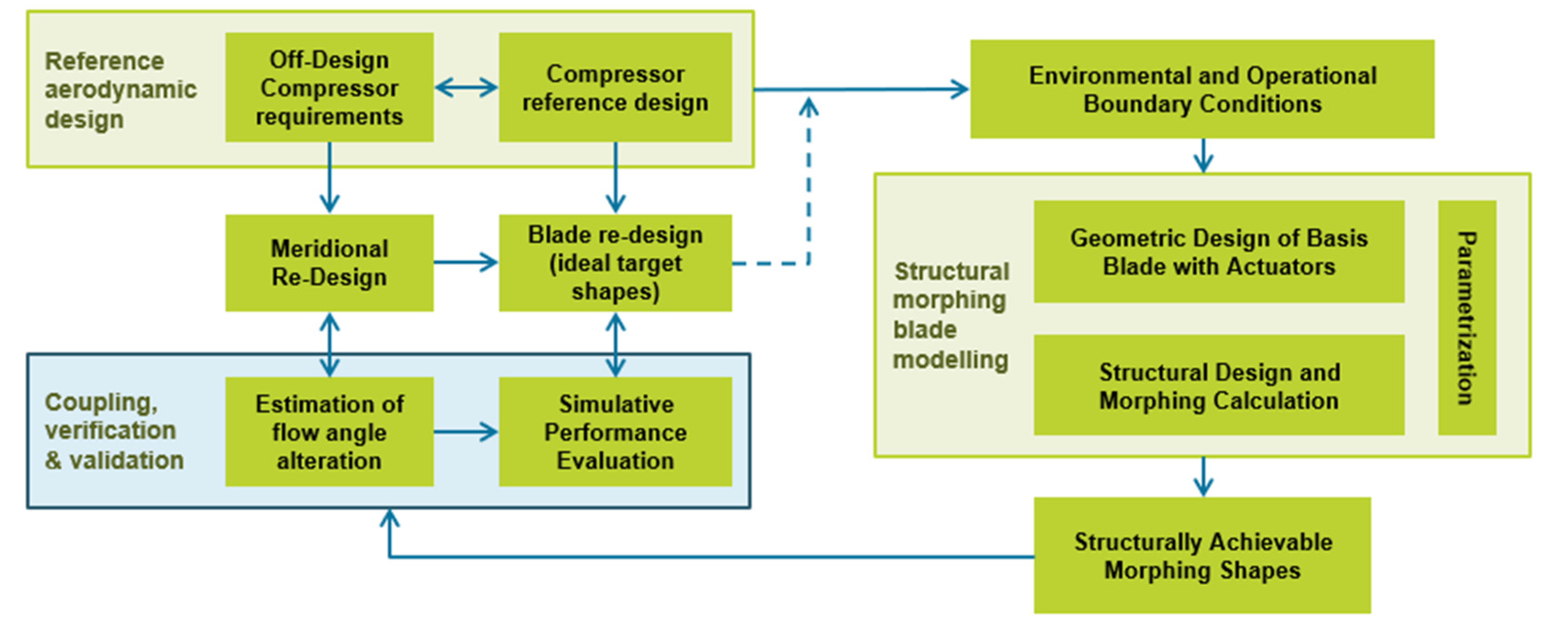
Figure 1 presents an overview of the coupled design loop. The starting point of the methodology is set by the reference design for the original, undeformed blade. By comparing the simulated operating range to varying design requirements throughout the flight mission, adaption scenarios are derived, and target pressure ratios as well as off-design mass flows are specified. The coupling process between both disciplines happens at three main levels, each covering a more detailed level of design.
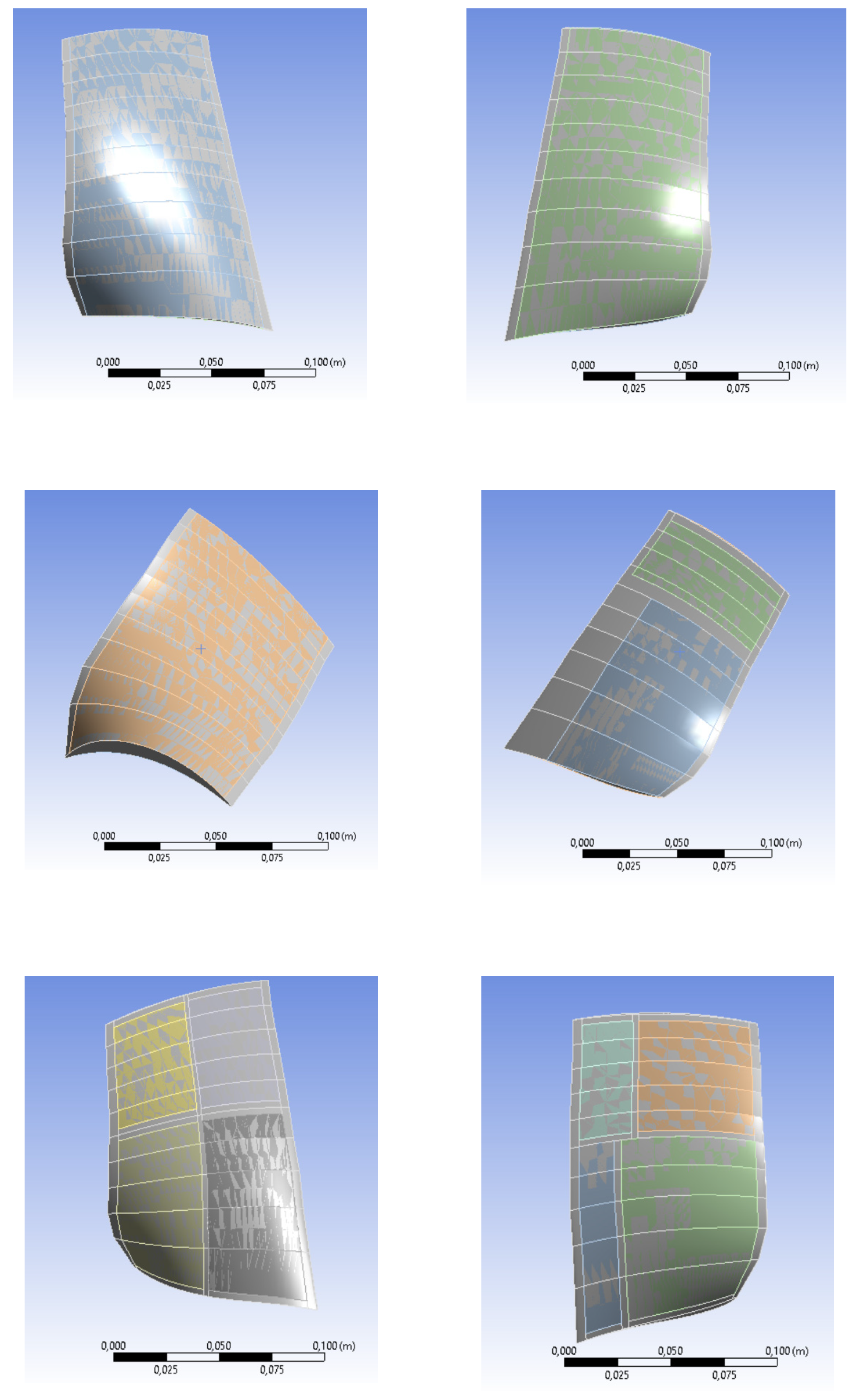
At a first level and as a first step, the off-design operating conditions along with the reference blade geometry are transferred to the aerodynamic design space. Within the aerodynamic design, first ideal inflow as well as flow deflection requirements for the off-design operating conditions are derived, using a streamline curvature calculation (as explained in Section 2.2.1). Simultaneously, a first qualitative assessment of the feasible deformations through the piezoceramic actuation is conducted for the structural design for different actuator configurations (Figure 2). Therefore, the reference blade and initial ideal target shapes are taken as input to analyze the different possibilities for structural morphing and calculating the achievable shapes.
Once simulated, the morphing shape results of the preliminary analysis are sent back to the aerodynamic analysis, where the achievable deformations are evaluated according to aerodynamic design criteria. A comparison of the spanwise deformation requirements with the structurally feasible deformations reveals adjustment requirements for the structural adaption concept as well as for the meridional design. In an iterative procedure, the actuator configuration and the aerodynamic vortex design are modified until a sufficient accordance between aerodynamic requirements and structurally feasible deformations is achieved. Within the actuation optimization, geometric parameters, such as the number of necessary actuators, their size and positions, the material properties and fiber orientations of the actuation fabric and the material possibilities for the blade itself, are covered.
The second step or level of the coupled design process focuses on the detailed analysis of the aerodynamic profile sections, comparing the reference blade performance to that of the structurally achievable morphing shapes. With the meridional design finalized and a preliminary actuator configuration selected, the rotor blade is re-designed by varying the camber design according to the aerodynamically predicted inflow as well as flow deflection variations. The derived target shapes are then transferred to the structural design, represented by the right side in Figure 1, to provide an orientation for the structural deformations. The ideal target design also serves as an input for the second coupling step, the simulative performance evaluation, wherein a detailed performance analysis of the aerodynamic target design as well as of the morphed blade is conducted. To reduce calculation effort and time within this coupling step, a representative Q3D (quasi-three-dimensional) evaluation approach is introduced on the aerodynamic side. By focusing on a tip section of the shape-adaptive system, the variation in profile performance through shape morphing can be evaluated, without relying on an expensive 3D flow analysis. Even though this analysis only gives a result for the tip section, it already sets a good reference for performance values and for assessing the agreement in morphing design requirements between structure and aerodynamics, especially due to the transonic flow behavior in the upper area of the rotor.
Based on the aerodynamic evaluation of the chosen section’s performance, an actuator configuration capable of reaching the required morphing amplitudes and types is chosen. The selected actuator configuration is then implemented in an extended FEA modeling process, through which a more detailed structural analysis is performed. The results of the structural analysis are calculated for the whole blade and sent back to the aerodynamic analysis for verification and validation. If these offer an agreement with the aimed-for requirements, a detailed 3D analysis can be performed as a final evaluation of the fully morphed rotor blade within the third and final coupling step. Hereby, 3D deformation and flow effects can also be considered. This closes the loop between aerodynamic design and structural morphing, as shown in Figure 1.
The design process is repeated for every pre-defined adaption scenario in order to evaluate the suitability of actuation concepts for different aerodynamic off-design requirements. The iterative character of the design methodology, with a three-step coupling approach of increasing fidelity, allows a continuous interaction between aerodynamic design and structural morphing conditions throughout the entire design process. With the introduction of a representative evaluation approach through Q3D simulations, the base for an efficient coupled optimization routine is additionally set.
2.1. Selection of the NASA 67 Rotor as Test Case and Reference Design
The NASA 67 rotor is a widely researched test case rotor developed by NASA and used since the 1980s for diverse modeling and experimental scenarios [22,23]. The rotor was originally used to collect tangential and axial velocities measured with the help of a laser anemometer (LA). Through these measurements, stream-wise and pitch-wise flow data were made available, offering insights into the detailed aerodynamic performance of the rotor. The front stage rotor was chosen for this study because the geometry design data as well as the flow data in the meridional design plane are well documented by Hathaway and Strazisar in [22], offering an extensive data base for referencing and evaluating the aerostructural design methodology. Additionally, the transonic and supersonic regions, with a peak relative tip Mach number of 1.38, offer a high potential for the application of shape morphing. Because the blade shock interaction is highly sensitive towards small changes in blade profile geometry, shape morphing is expected to have a high impact on the rotor performance.
For the transformation of the NASA 67 rotor into a shape-adaptive system, the original geometry data are extracted, refined and smoothed. Due to the low resolution of the rotor leading and trailing edges, circles are iteratively fitted until a tangential transition between suction and pressure sides is achieved.
By remodeling the original reference geometry with a parabolic mean camber line [24] and a CSM (Class Shape/Class Form function Methodology) thickness distribution [25], the adaptability of the reference design and the flexibility for the creation of aerodynamic redesigns is increased. Additionally, relevant blade profile design parameters, such as the turning angle, stagger angle and leading and trailing-edge metal angles, can be derived as reference values for the aerodynamic redesign methodology. The placement of the profile reference sections for the rotor design is an important coupling parameter between aerodynamic pre-design, structural deformation simulation and evaluation. They are kept constant as a common reference throughout the coupled design process. For the modeling of the reference geometry, the number of reference sections is increased by interpolating the derived design parameters in radial direction. Thereby, 20 equally spaced streamlines with a linear slope within the blade row are created in the meridional design plane and defined as reference locations for the profile section throughout the shape adaption process (as explained in Section 2.2.1.).
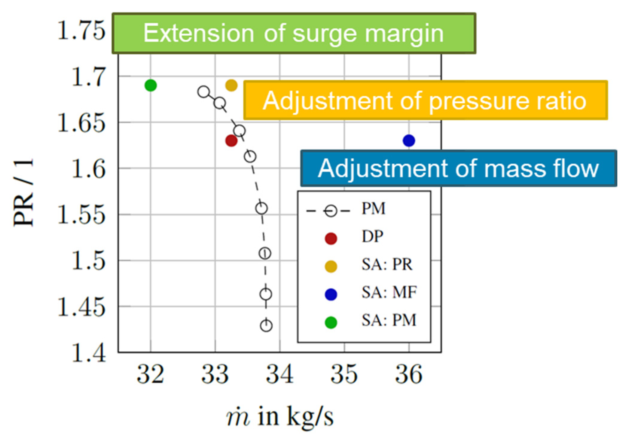
After remodeling the reference geometry, the stage performance is evaluated in a CFD simulation. For the simulation, a structured mesh is created in AutoGrid with a y+ value of approximately 1 at the blade’s surface, the hub and the shroud end wall. For the stationary simulation of the speed line at design speed, a k-ω turbulence model is selected, and the static outlet pressure is iteratively increased until simulation divergence predicts the simulative onset of stall. Based on the simulated operating range and speed line, where the red dot marks the literature design point, different adaption scenarios are derived, which then serve as input for the aerodynamic design methodology (Figure 3). Three shape adaption scenarios are exemplarily selected for this study.
- Starting from the design point in red, the design point mass flow is shifted beyond the choke limit of the rotor (blue). This possibility is particularly interesting for the development of alternative energy concepts, such as fuel cells, which are highly dependent on different mass flows for their power output [3].
- By adjusting the design point pressure ratio, while keeping the mass flow constant, an alternative for variations in rotational speed is assessed (yellow).
- Extending the surge margin by moving along the performance curve (green) improves part-load performance, which is especially critical when the airplane takes off or accelerates during flight and the danger of compressor stall has to be avoided [26].
2.2. Aerodynamic Design Methodology
The main goal within the aerodynamic design branch of the methodology is the creation of target designs in order to evaluate, but also to serve as a reference for, structurally feasible deformations. The feasible deformations pose additional boundary conditions for the aerodynamic design, which have to be considered early on in the design process. Therefore, the aerodynamic design is split into the meridional design and the blade design, continuously including structural design specifications in the design process.
2.2.1. Meridional Design
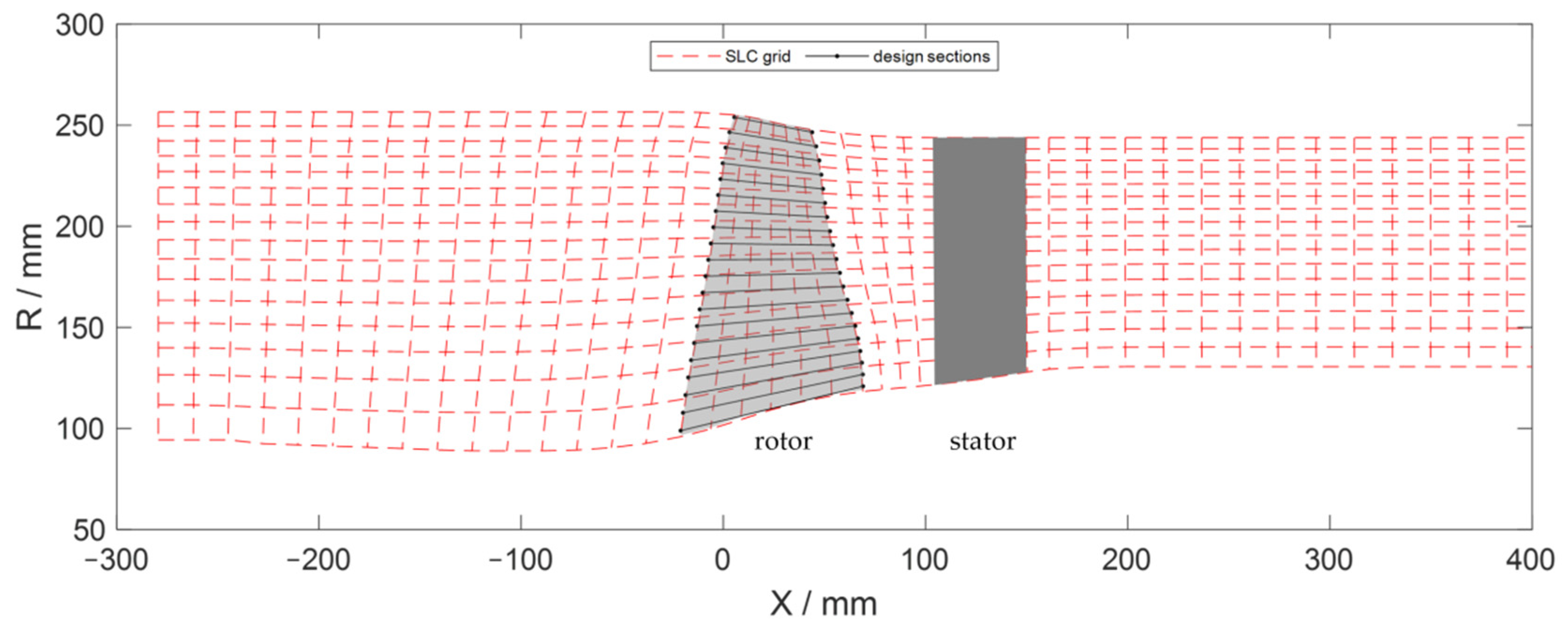
For the assessment of the flow angle variations due to the new operating conditions, a two-dimensional throughflow streamline curvature methodology (SLC) is implemented (see [27]). The throughflow calculation iteratively solves the radial equilibrium equation along with the continuity equation to predict the meridional distribution of relevant flow quantities, based on the channel geometry, the blade leading and trailing edges and the required mass flow and total pressure ratio of the compressor stage (Figure 4).
The spanwise required increase in total pressure within the rotor is transformed into a vortex distribution at the trailing edge, creating a direct interface to specifically adapt the aerodynamic design to the feasible structural deformations. This is achieved by varying the n-factor in the generalized free vortex design equation:
The hub loading is controlled for the specific adaption scenario, directly influencing the spanwise variation of inflow angle β1 as well as flow deflection requirement Δβ [13]. The required geometry boundary data are derived from the reference design point geometry, while the new design point conditions (mass flow and pressure ratio) are defined though the selected adaption scenarios.
For the transformation of the aerodynamic streamline solution into aerodynamic morphing requirements for the derivation of the piezoceramic actuation concept, the variation of relative inflow angle
and flow turning
are calculated according to Figure 5 and interpolated onto the pre-defined meridional sections. These values are then used to evaluate the suitability of the structural shape morphing for the selected adaption scenario.
2.2.2. Blade Design
With the relative inflow and outflow angle variations defined through the SLC calculation for the selected adaption scenario, the required blade turning
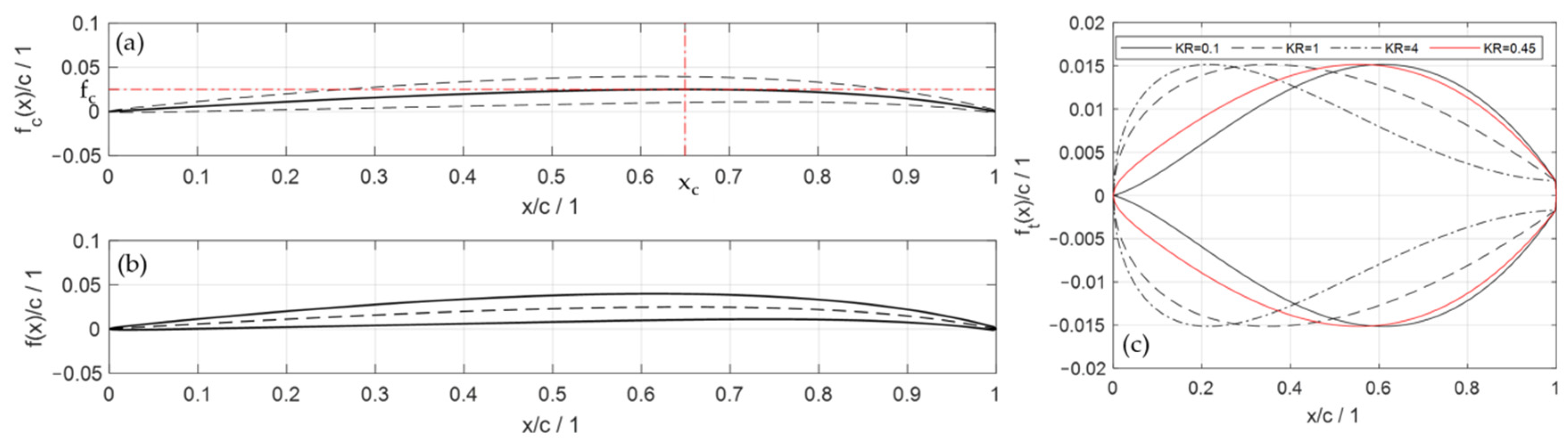
can be calculated, and a new blade geometry is derived (Figure 5). This geometry serves as an initial target geometry for the structural deformations. By specifying the maximum camber fc and its chordwise position xc a generalized parabolic mean arc is created to model the blade camber, following Schlichting [24] (Figure 6).
Starting from the reference camber, the blade turning can be adapted by varying both camber modelling parameters (xc, fc), offering two adaption possibilities for the aerostructural coupling. While the blade turning increases linearly with the blade maximum camber, the impact of a maximum camber position variation on the achievable blade turning variation increases with the deviation from the symmetrical configuration at xc = 0.5. Although this effect is similar for a rearward and frontward shift, a rearward shift is expected to have a positive impact on the performance of the target designs, due to the suction-side curvature reduction towards the compression shock in the tip region of the rotor sections [29]. With a rearward location of the maximum camber position, the impact of fc variations is additionally amplified, which is especially relevant for a possible reference design adjustment. The resulting leading-edge camber angle α1 directly influences the required blade stagger angle λ and increases with the maximum camber or a relocation of the maximum camber position towards a centered position (Figure 7).
The thickness distribution
is modeled separately following the CSM methodology, described in [25], where the class function
defines a basic profile form, while the shape function
serves as a weighting function to specifically control maximum thickness as well as maximum thickness position through the KR factor. Although [30] showed that an extension of the CSM modeling approach offers an improved modeling capability for transonic as well as supersonic profile shapes, a droplet form was chosen for all profile sections through selecting n1 = 0.5 and n2 = 1.0, as the re-engineering accuracy for the NASA 67 rotor is sufficient for a preliminary feasibility study. Under the assumption that the piezoceramic actuation only affects the profile camber, variation of the thickness distribution is limited to the rotor reference design, while the blade profile thickness remains constant throughout the shape morphing.
By modeling the blade camber, through adapting the maximum camber and its position to fit the turning requirement, the leading-edge camber angle α1 is defined, and the required spanwise stagger angle is derived according to Figure 5.
For the preliminary study introduced within this paper, the aerodynamic inflow incidence angle i is neglected. The stagger angle λ therefore depends on the leading-edge camber angle α1 and the rotor inflow conditions β1 predicted by the SLC calculation. While the camber design parameters xc and fc influence the blade shape and the spanwise morphing of the blade turning, the stagger angle describes the spanwise variation of blade twist and therefore the third morphing parameter for the shape adaption and the coupled aerostructural design methodology.
The staggered aerodynamic target profile sections are then shifted into position and projected onto the conical stream surfaces through the rotor, located coaxially around the machine axis at the pre-defined reference positions (Figure 4).
2.3. Structural Analysis Method and Coupling Approach
As previously discussed, the sections originating from the meridional design of the blade constitute the basis for the aerodynamic design of the blade and are also crucial for the exchange between aerodynamic and structural design space and for the development of the coupled design. For this reason, they are also the starting points of the structural design process and are maintained throughout the structural modelling.
2.3.1. Geometric Design and Parameterization
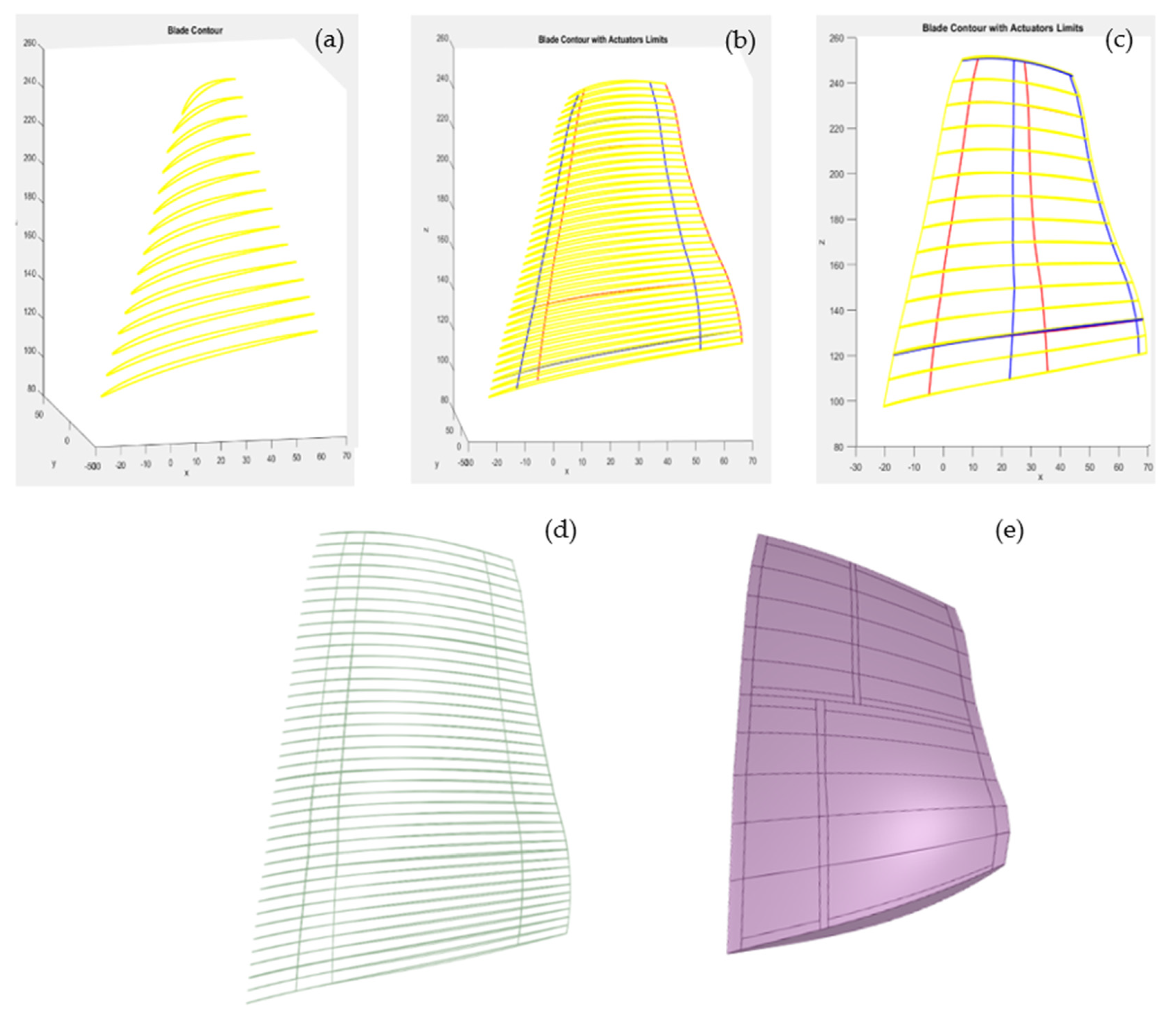
The first step in every structural design process is the definition of the geometry. To define and design it, a wireframe structure modeled following the aerodynamic sections is defined in Matlab and constitutes the skeleton for the blade structure (Figure 8, top left). Based on this skeleton structure, different geometric actuator configurations can be parametrized and calculated for developing a wide variety of structural models.
The number of streamline sections used for the development of the geometric models depends on the level of detail that is desired for the exchange between aerodynamics and structure. The higher the number of sections, the more detail is possible, but also the costlier the process becomes. For this study, 20 sections were chosen as a compromise.
In addition to the wireframe structure, the lines delimiting the actuators’ surfaces are also calculated in Matlab and added to the skeleton structure. The positions of these lines are considered as design parameters and can be variated according to the desired actuator numbers and sizes and according to the target morphing shapes. The two top right images in Figure 6 illustrate two possible exemplary configurations. The lines in red delimit the actuators at the suction side of the blade, and those in blue mark the actuators for the pressure side.
Based on the developed geometric parametric models, a CAD design is developed in ANSYS SpaceClaim. A point cloud structure based on the wireframe skeleton structure and on the calculated actuator positions serves as a basis for the CAD modelling process (Figure 8, bottom left). Since the aerodynamic sections are essential for data exchange and analysis with the aerodynamic design process, these sections are preserved in the CAD design model. The actuators delimiting lines are also kept, since their positions are set as parameters for the geometric model. This provides flexibility for testing various actuator configurations regarding the number of actuators, their positions and sizes and sets a basis for an optimized coupled design process. All these parameters together allow for different deformations later on.
It is important to note that even though we here focus on the case study of the NASA 67 rotor, the method for the structural design of the blade and the geometry generation are completely independent of the basis blade geometry and can easily be adapted to other morphing blade designs and concepts.
2.3.2. Structural Modelling and Material Parameters
The structural design modelling of the blade is performed in ANSYS Workbench and begins with the setup of the material properties for both the blade and the actuators. The model of the blade is divided in two sets, one for the blade itself, as a solid body and modelled with quadratic solid elements, and one for the actuators, using shell elements. This separated modelling approach not only allows for more flexibility regarding the material modelling for each component but also facilitates the handling of different actuator configurations and blade geometries. Furthermore, it enables the handling of material properties as parameters themselves. Figure 9 shows a possible architecture for the case study of the NASA 67 compressor blade.
In order to enable a wide range of possibilities regarding material combinations, a set of different common metals for current compressor blades is set up and can be variated as parameters for different blade modeling possibilities. For the case study of the NASA 67 rotor application, three common metals were chosen and tested: steel, aluminum and a titanium alloy. The most promising material for this specific application is the titanium alloy, already known as one of the most frequently used materials for compressor and engine blades [4]. Titanium is chosen because it offers enough flexibility for morphing while still guaranteeing structural integrity for the blade under the loads a first-stage compressor can experience. According to the specific application, different suitable materials or a multi-material blade structure can also be considered.
A summary of the main material properties used for the test case with the NASA 67 compressor blade is presented in Table 1. These properties are the standard properties proposed by the software ANSYS and Granta Design [31] for titanium alloys and correspond with standard alloys used for compressor blades for current turbofan engines [32,33].
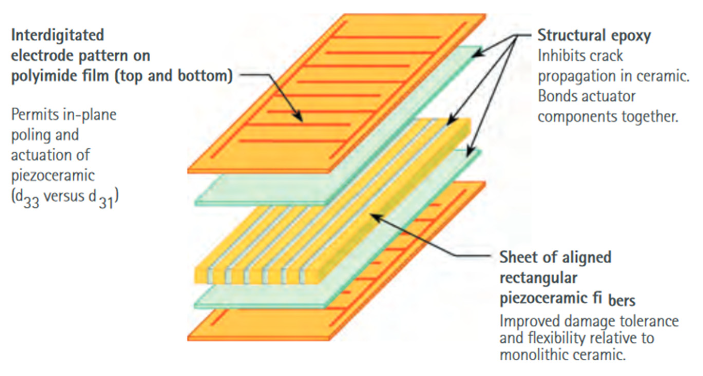
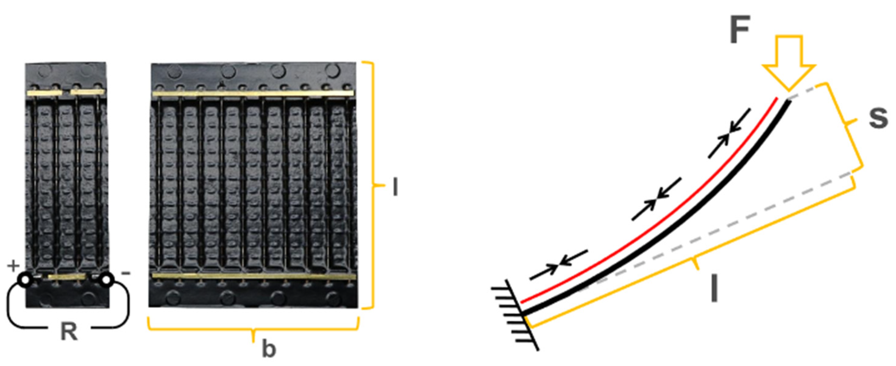
The actuators’ material modelling follows a fiber-composite modelling scheme. Current active materials, such as Macro-Fiber-Composite Actuators (MFCs) [20] or Shape Memory Alloys (SMAs) with planar bending actuators [21], consist of fibers of the respective material. These fibers are aligned together and fixed in that position with the help of a flexible material that provides an interface for mounting and connecting points to a source of energy (in the case of the MFCs) or to a source of heat (in the case of the SMAs). When the source of energy or heat is activated, the fibers can expand or contract, inducing a change of shape in the surface they are mounted onto, leading to morphing. Figure 10 presents a schematic representation of the structure of an MFC actuator, and Figure 11 illustrates the morphing principle for such actuators.
For the exemplary case of the NASA 67 rotor blade, MFC piezo-actuators have been chosen for the modelling. These actuators allow deformations that are large enough for the studied case. Their potential has been proven in past studies for similar applications, such as the design and experimental investigation of shape-adaptive compressor blades for their use in a compressor cascade experiment performed by Krone and Huxdorf, as described in [19].
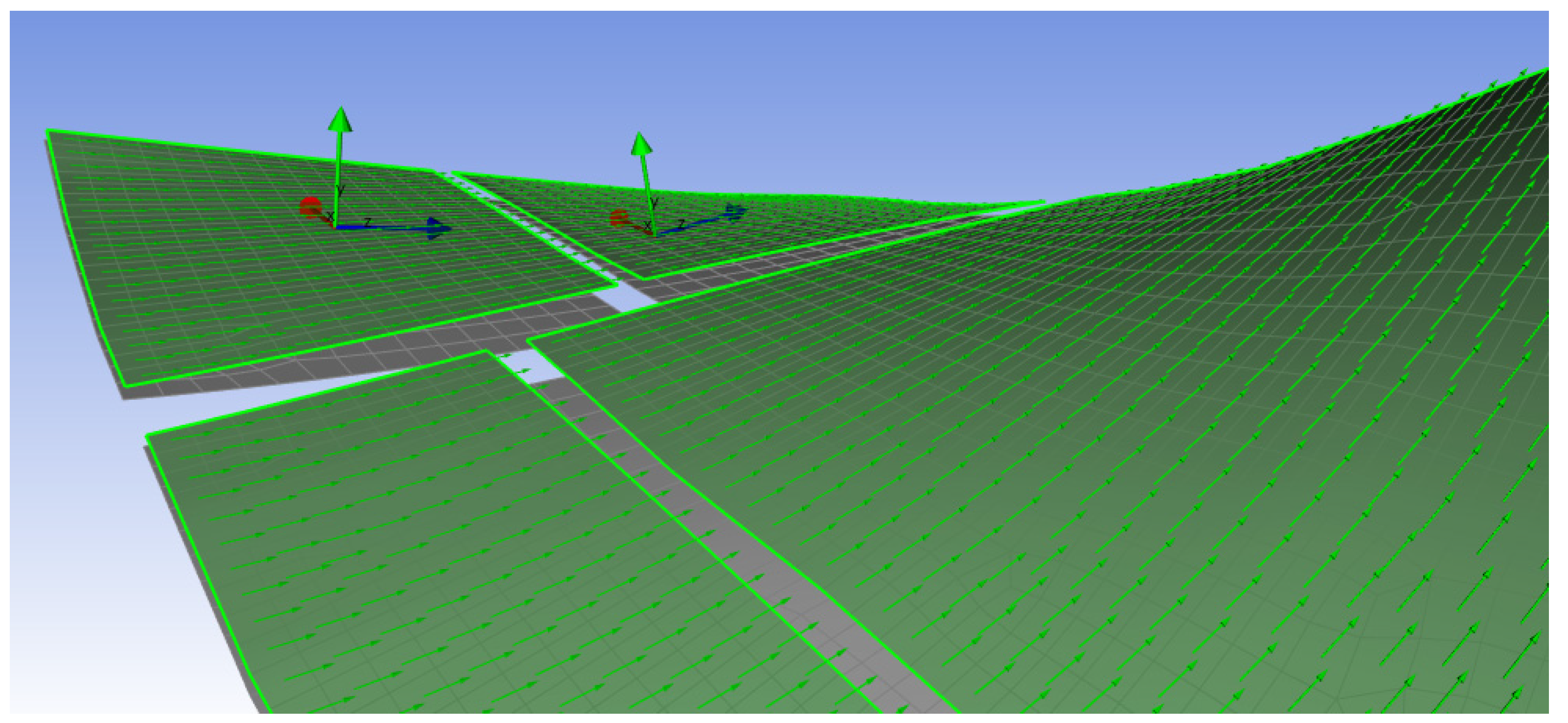
The structural modelling for the NASA 67 compressor blades and for the developed method is carried out in the Ansys Composite PrepPost (ACP) module of Ansys Workbench. This tool enables the modelling of layered composites so that it is possible to simulate the behavior of different actuator stack-up configurations and also to test different actuation directions. This allows for independently controlling each actuator by, for example, giving each a different actuation direction or a different stack-up number, thereby enabling different morphing behaviors. The properties for controlling the actuation directions and actuation modes are also set up as material parameters in the structural modelling approach. Figure 12 shows an exemplary model view developed for MFC actuators with the actuating fibers distributed in the spanwise direction and with a chordwise actuation direction. In the illustrated case, all fibers follow the same actuation direction, but these can be flexibly changed.
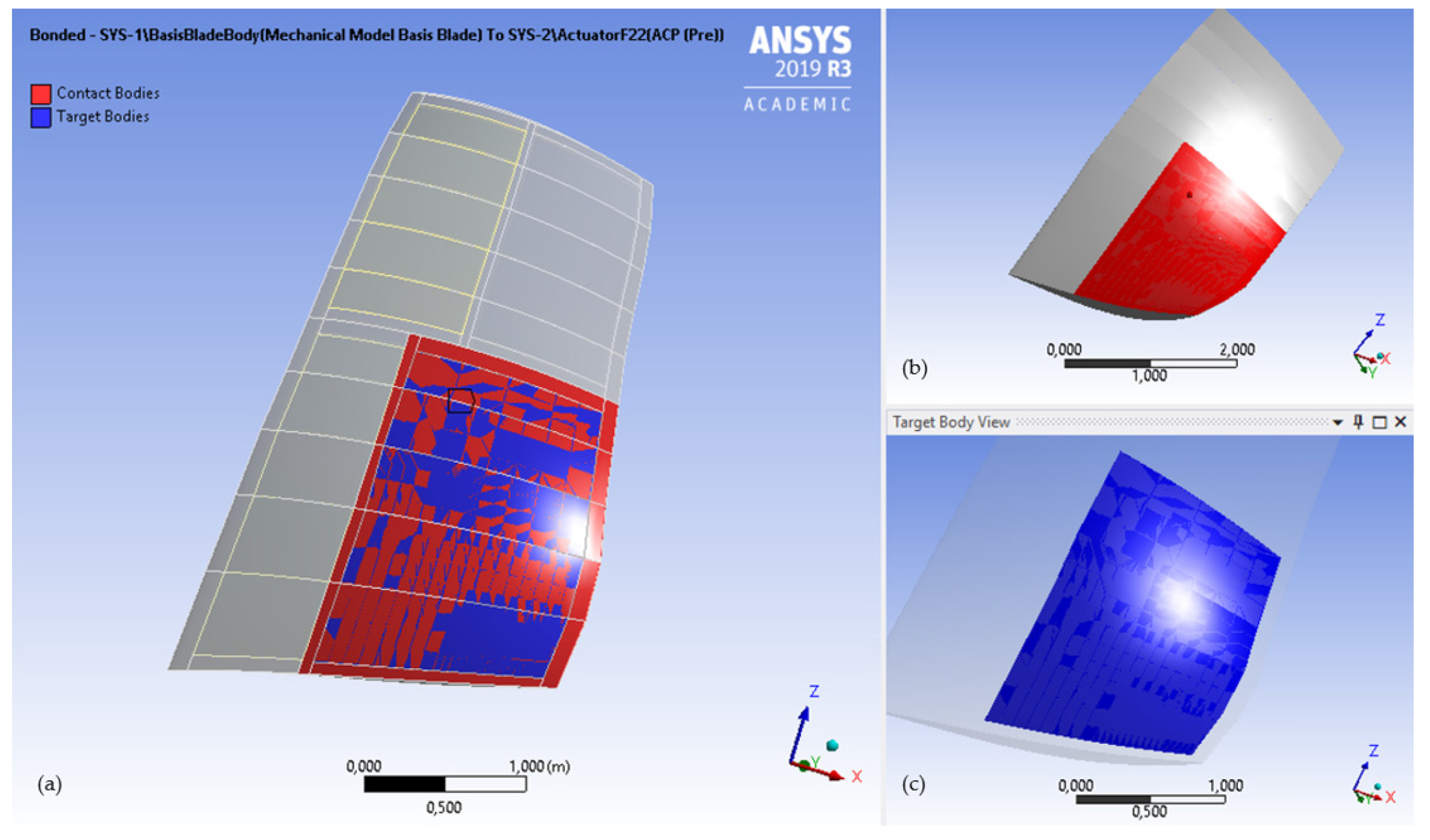
The next step of the structural modelling process brings the blade and actuators models together. In the case of the NASA 67 rotor compressor blade, the actuators are modelled as embedded surface actuators and therefore represented with a bonded contact approach. The contact surfaces consist of all the limiting surfaces of the blade that are in direct contact with the respective actuator and that serve to allow the transmission of the actuator’s deformation to the blade. Bonded contact surfaces are restricted from penetrating each other. It is this contact modelling approach that allows accurately simulating the morphing behavior of the blade and transferring the deformations from the integrated actuators to the blade itself. Figure 13 illustrates an example of contacting surfaces for the NASA 67 test case model.
The contact modelling behavior of the blade with actuators is complemented by a thermal analogy behavior modelling that represents the actual actuation behavior transferred from the integrated actuators towards the blade’s body. The considered actuation materials for this study are piezoelectric actuators and shape memory alloys (SMAs). In order to have a modelling process that can easily adapt to both types of materials, a thermal analogy capable of reflecting the electric behavior of the MFCs has been calculated. In order to use SMAs instead, modifying the boundary conditions is all that needs to be changed in the model. A summary of the mechanical properties used in the model of the piezoactuators as used for the NASA 67 rotor case study is shown in Table 2.
Based on these properties and the MFC actuators properties presented in [20], the boundary conditions for the temperature analogy model were set as temperature constraints for the active actuating surfaces, with +1000 °C for the equivalent expansion behavior and −1000 °C for the equivalent compression behavior. These conditions represent a simplified approach for actuators with the same expansion and compression deformation values and must be further tuned for more detailed studies, especially for actuators with different expansion and compression behaviors. The coefficient of thermal expansion values in Table 2 are what create the thermal analogy behavior for the model. These coefficients, together with the corresponding temperature boundary conditions, simulate the actuation process. They were calculated based on the strain and electric field properties from the material data sheets in [20] for a representative MFC actuator. In order to simulate the electric deformation behavior under a given voltage, the thermal coefficient allows obtaining the same deformation value, only under thermal boundary conditions instead of electric ones. In the modelling process, the mechanical properties of the actuators are exactly the same, and no thermal dilation behavior is considered for the blade, so that only the mechanical actuation effects are transferred from the actuators into the blade’s structure, as is the case when using such actuators.
The modelling of the binding surface of the blade, the area that would be connected to the blade’s mounting disc, is considered as a fixed support distributed all along the blade’s root in a simplified approach. A detailed analysis of this area was not considered for this first study.
Figure 14 shows examples of both boundary conditions for a blade with two large surface actuators, one on the pressure side and one on the suction side.
2.3.3. Structural Analysis
All the elements in Section 2.3.3 represent the setup for the structural analysis of the blade. In Ansys Workbench, this analysis runs as a static structural analysis, capable of determining the displacements, stresses, strains and forces experienced by the blade during morphing and ensuring, for example, that the blade will not deform beyond its structural limits. A steady loading response is assumed, and no aerodynamic forces or dynamic conditions are considered for the model at this phase of the study.
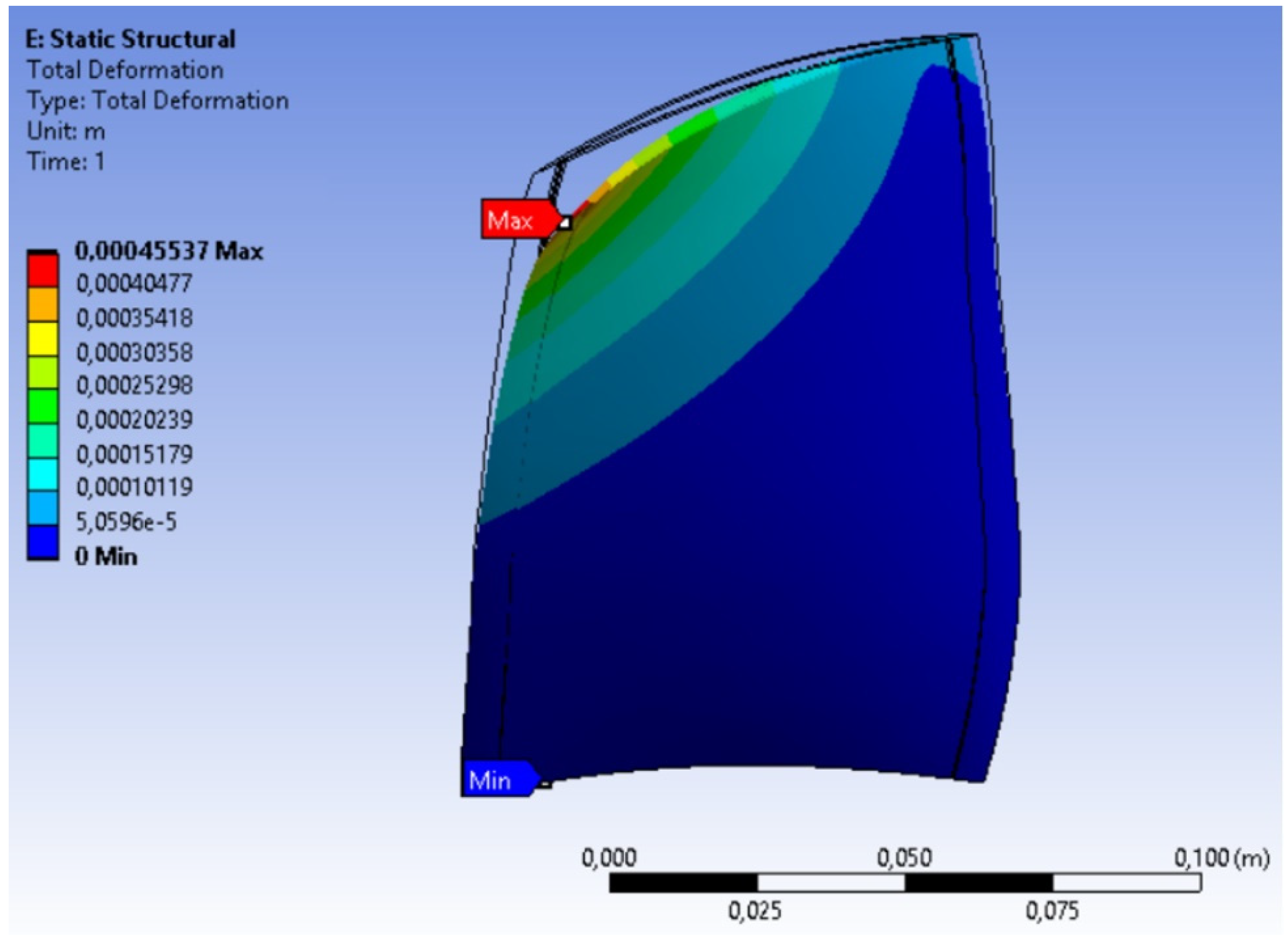
Figure 15 presents exemplarily the deformation results for a blade with two large surface actuators, one at the suction side (45° actuation direction) and one at the pressure side (135° actuation direction). When actuated together and because of the relative perpendicular actuation directions, a twist and bending deformation can be achieved. In this case, the maximum deformation (red area) is reached at the blade tip and presents a change in the stagger angle of the blade. Because of the complete attachment of the root area, no deformations are experienced by the bottom section of the blade. Since the deformation values are very small, neither the critical stresses and strains of the blade’s body nor those of the actuators are surpassed.
It is important to note that even though the deformation values remain small, achieving deformations in a range of 0.5–2° at the leading edge can already lead to significant effects on the aerodynamic performance of the blade and of the compressor.
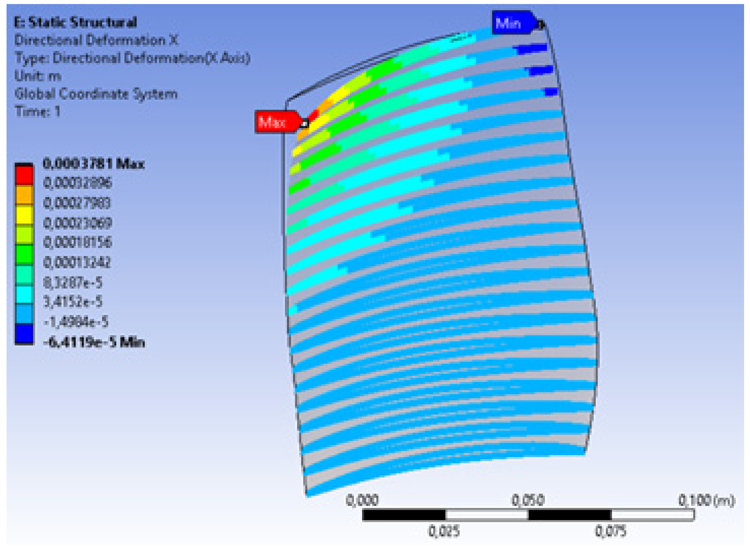
In order to make the results of the structural analysis exploitable for aerodynamics, the deformation results at the exact positions of the original aerodynamic sections are calculated. An example of the deformation values in chordwise direction is illustrated in Figure 16. These results are exported as a deformed cloud of points representing the morphed blade geometry and can then be used for an analysis of aerodynamic performance with the help of the Q3D approach. This enables a simplified and representative evaluation, not only of the aerodynamic sections, but also of the blade’s behavior as a whole.
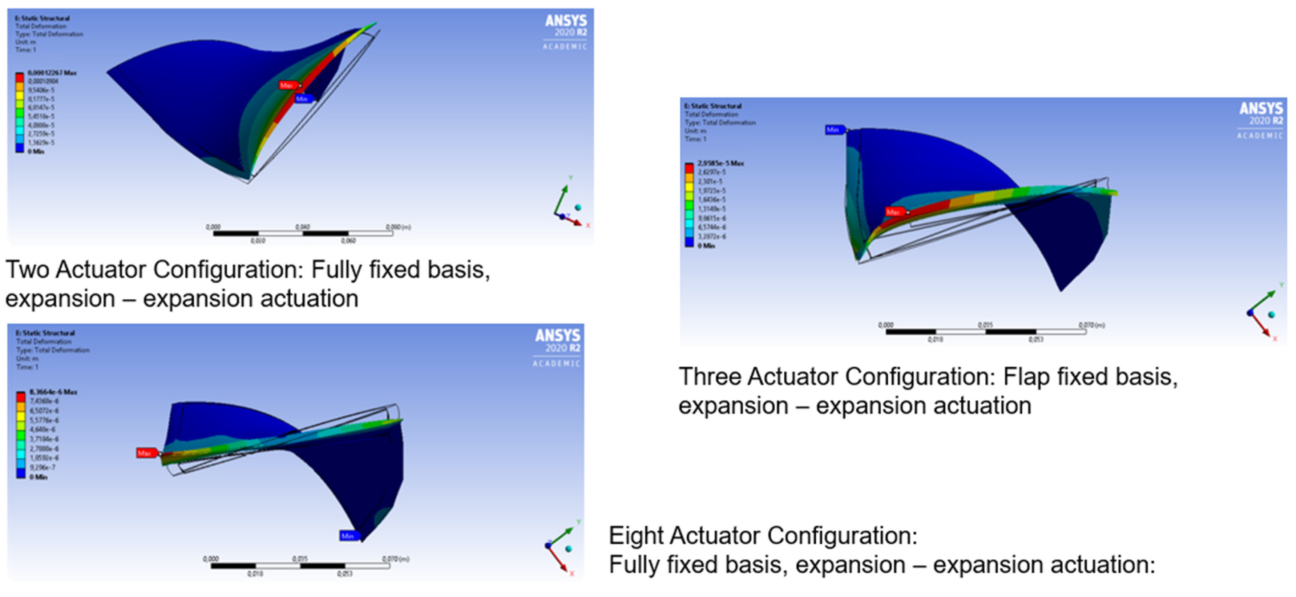
Having the possibility of using different actuator configurations, sizes, materials positions, numbers and actuation directions leads to a wide range of possible morphing behaviors. Figure 17 illustrates qualitatively other possible morphing shapes for the NASA 67 compressor blade.
2.4. Aero-Structural Coupling in the Meridional Plane
For the comparison of aerodynamically required deformations and structural feasible morphing, the deformed grid data from the FEM simulation are analyzed according to aerodynamic design criteria and angular definitions (Figure 5). At this point in the coupling methodology, two challenges occur. Since the blade has been deformed, the structure of the exportable FEM data does not exactly follow the aerodynamic input. Furthermore, since FEM calculations do not need as much detail as flow simulations do, the mesh resolution of the FEA is much coarser than the one required for detailed CFD simulations, especially at the leading- and trailing-edge areas. To overcome these challenges, a further post-processing of the mesh grid data is required, prior to the aerostructural coupling. Since the numbering of the grid points follows an internal indexing set up by the Ansys Mechanical modules, the grid points have to be assigned back to the original aerodynamic design sections in the meridional plane. By keeping the blade sections throughout the structural analysis, the sorting process is simplified. With the blade sections separated and radially sorted, the 3D sections are transformed back into the 2D design plane to calculate the spanwise blade staggering of the deformed geometry and to rotate the blade profiles back into design position (Figure 6). Furthermore, a separation of the suction and pressure sides is necessary to allow blade camber reengineering for every profile section. Calculating the chordwise slope of the re-engineered profile camber yields variation of the leading-edge and trailing-edge camber angles αi due to the shape morphing, and the structurally feasible turning variation ΔΔφ can be calculated according to Figure 5. The feasible variation in section-wise blade turning is then directly compared with the desired aerodynamic target design requirements.
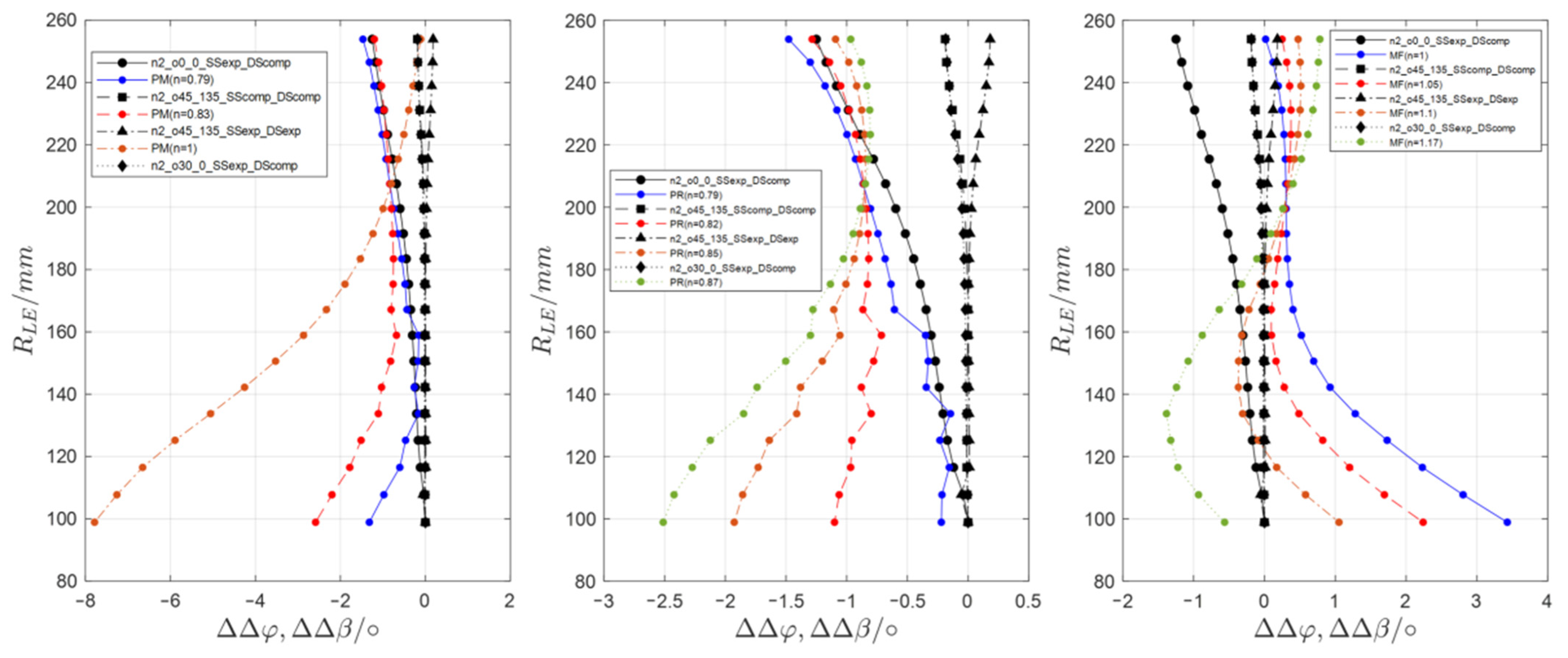
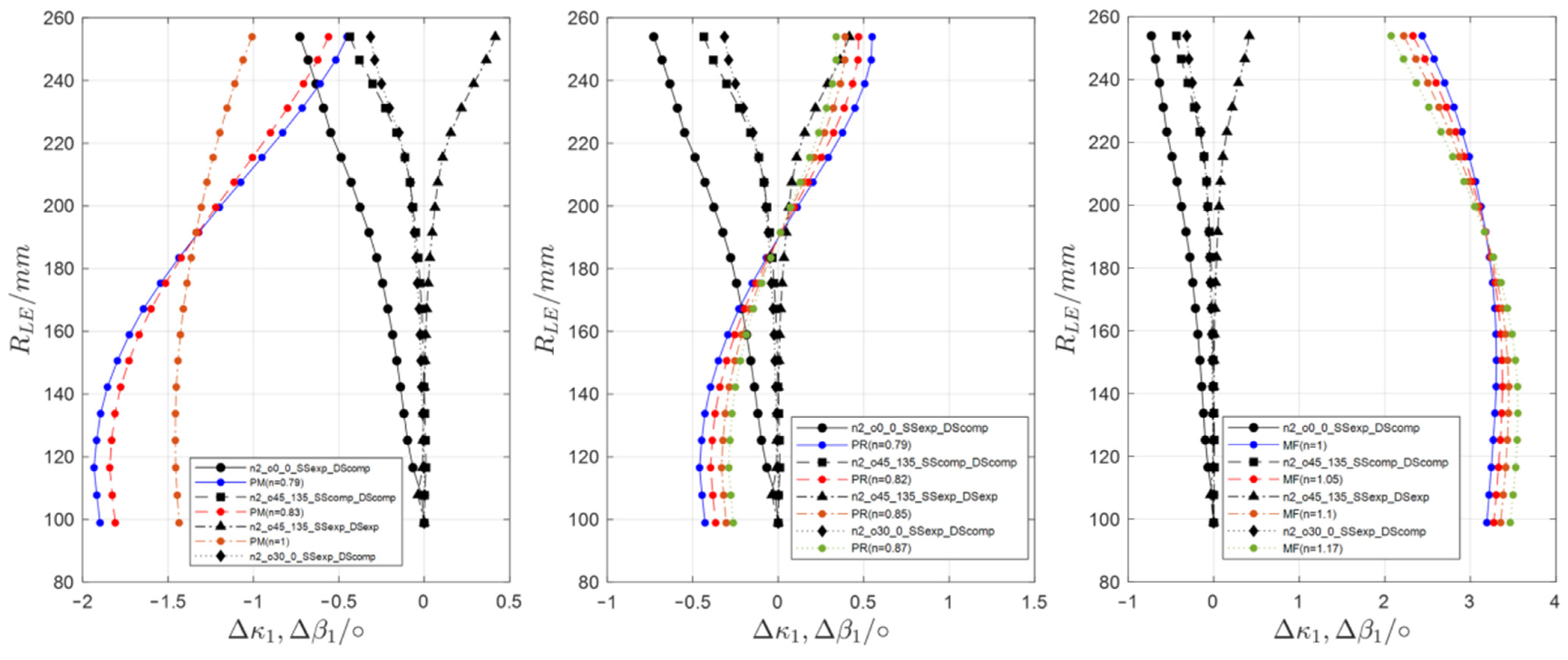
The three predefined shape adaption scenarios are separately analyzed, comparing the aerodynamically derived flow angles with the feasible structural deformations induced by the piezoceramic actuator configurations. In order to evaluate the pressure rise capability of the morphed rotor blade, the required variation in flow deflection ΔΔβ is compared to the achievable morphing of the blade turning ΔΔφ (Figure 18). Additional to the deflection requirement, the variation of the leading-edge metal angle κ1 has to match the altered inflow angle β1, in order to achieve the mass flow required by the adaption scenarios (Figure 19).
The iterative character of the design methodology becomes directly apparent when the feasible deformations are generally compared to the flow deflection requirement of the PM scenario with a standard free vortex law, as shown in Figure 18, left. While the variation in flow deflection requirements is highest towards the blade hub, the hub sections remain nearly undeformed due to the blade clamping into the hub. Instead, the achievable deformations increase towards the blade tip, where for all actuation concepts the highest morphing potential is visible. This poses a major conflict for aerostructural coupling and for the creation of aerodynamic target designs. To match the deformation pattern, the hub loading for the new design point is altered by varying the n-factor of the vortex design (equation 1), until the aerostructural contradiction is reduced to a minimum, without exceeding the blade loading limits defined by the diffusion number. Thereby, the best agreement between aerodynamic requirements and an actuation configuration can be identified for the following simulative evaluation. For the PM- and the PR- scenario, the pressure ratio for the redesign is increased, causing a spanwise raise in deflection requirement. By unloading the hub of the redesigned rotor, the deformation requirement at the hub shifts towards the blade tip. As the actuation concept with two actuators, a zero degree fiber orientation, expansion of the suction-side actuator and compression of the pressure-side actuator yields the overall highest variation of blade turning, an n-factor of n = 0.79 is selected for both scenarios to match the feasible deformation distribution conveniently.
Similar to the previous two adaption scenarios, a constant vortex design for the MF redesign results in the highest deformation requirement towards the hub (Figure 18, right). As an increased mass flow is selected for this adaption scenario, while the pressure ratio remains constant, the required spanwise blade turning has to be reduced compared to the reference design. This determines an increase in hub loading, which is limited by the diffusion number, and the exclusion of a spanwise altering deformation requirement. With these limitations, n-factors higher than 1.1 are not feasible from a structural standpoint, leaving the free vortex design with n = 1.1 as the best option for the MF redesign (Equation (1)). With this option, a deviation between aerodynamic design requirements and structural deformation feasibility remains. Additional to a deviation in turning requirement at the blade hub, a reproduction of the structurally feasible deformations towards the blade tip is not entirely possible without causing a spanwise altering deformation requirement. As a compromise, an actuation concept with two expanded actuators, a 45° suction-side and a 135° pressure-side fiber orientation seems to be best suited for this adaption scenario.
With the preliminary selection of vortex design and actuation configuration based on the turning variation as the driving coupling parameter, the incidence through shape adaption represents an additional quality criterion for the evaluation of the accordance between aerodynamic target design and structurally feasible deformations.
For the quantification of the spanwise shape adaption incidence, the variation of the relative inflow angle, Δβ1, according to the SLC solution is compared to the structural variation of the leading-edge metal angle, Δκ1, which, again, is a result of the leading-edge camber angle variation Δα1 as well as the stagger angle variation Δλ (Figure 5).
The shape adaption incidence allows a further evaluation of the spanwise deviation between inflow angle variation and feasible leading-edge metal angle morphing. An elevated incidence would diminish the rotor efficiency through increased profile losses up to unstable operating conditions in the selected adaption scenario and should therefore be minimized.
For the PM scenario, the highest shape adaption incidence occurs in the subsonic blade hub area, where the rotor is expected to show an increased incidence tolerance. Towards the transonic and supersonic inflow regimes of the upper rotor sections, the shape adaption incidence decreases (Figure 19). This is beneficial for the selected actuation concept, since the transonic and supersonic profile sections are highly sensitive towards increased inflow incidence. However, an elevated incidence tolerance, especially for the subsonic rotor sections, should be considered for the reference design of a shape-adaptive compressor stage. Comparing the same actuation concepts to the PR redesign with n = 0.79 yields a reversed spanwise shape adaption incidence distribution. The incidence is moderate in the hub area, with a minimum at approximately 45% rotor height and a maximum of 1.4° at the supersonic blade tip section (Figure 19). This contradicts the suitability of the available actuation concepts, as the selected design point might not be achievable, due to increased profile losses in the tip region of the deformed rotor.
The increased design point mass flow in the MF scenario causes a decrease in the spanwise leading-edge metal angle over all blade sections, with a maximum of 3.2° at approximately 45% rotor height. Only a minor improvement is achievable through a vortex law alteration towards an increased hub loading. Since the variation in relative inflow angle Δβ1 is dominant for this adaption scenario, this result indicates that the initially specified mass flow variation of 2.75 kg/s is not feasible through shape adaption. However, the selected actuation concept (nact = 2, o1 = 45°, o2 = 135°, both actuators expanded) achieves a reduction of shape adaption incidence in the rotor tip region and is therefore selected for a further simulative investigation.
2.5. Representative Simulative Evaluation
Under the assumption of a non-deformable thickness distribution throughout the adaption process, only the deformed and re-engineered blade camber is extracted from the FEM-post data to prepare the second step in the coupling methodology. The second level of coupling starts once the conceptual design phase of the morphing blade has been concluded and a qualitative compromise of possible spanwise morphing distributions has been found. For the aerodynamic redesign, the vortex designs are chosen according to the available and feasible deformations.
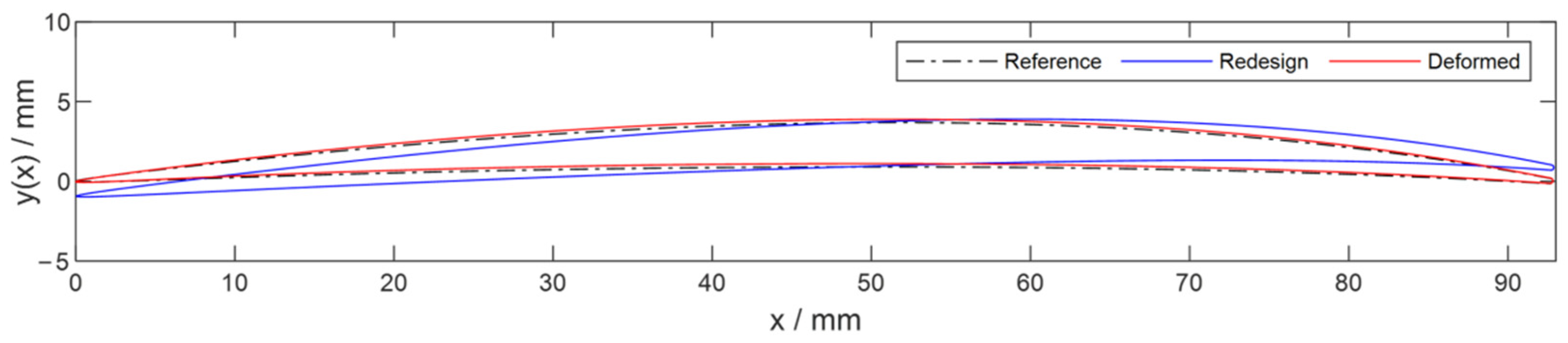
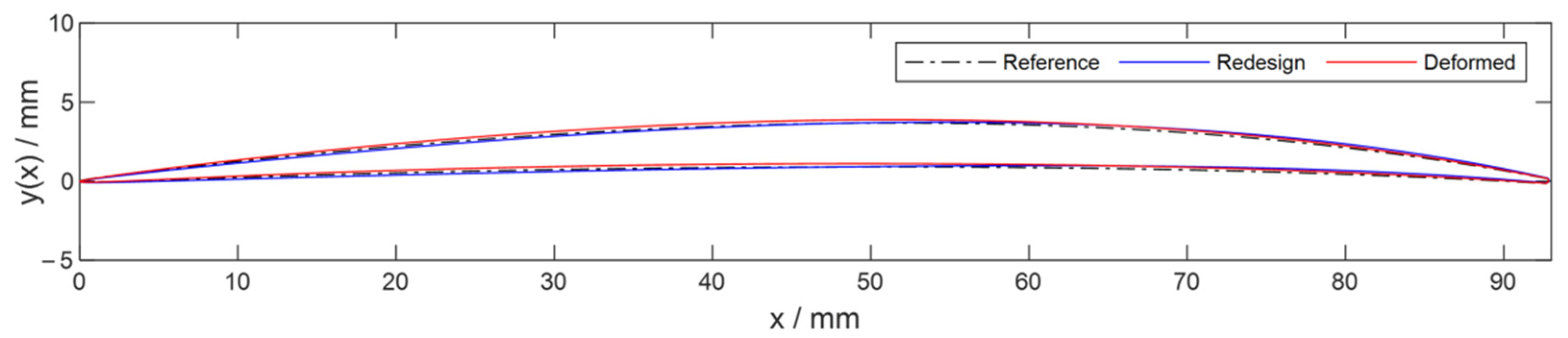
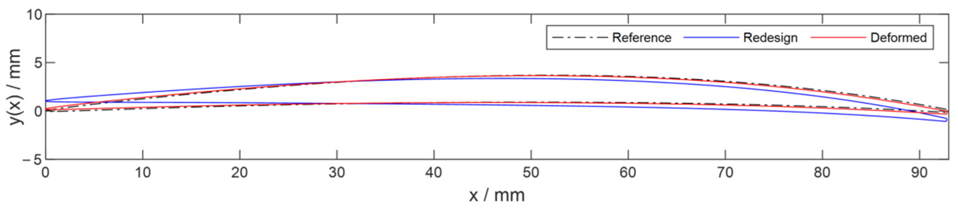
Depending on the adaption scenario, one of the free blade morphing parameters fc, xc or λ is specified, defining the others through the required blade turning and inflow angle. With the highest deformations concentrated in the blade tip region, leaving the lower blade sections basically undeformed, the transonic behavior of the blade profiles plays a major role, emphasizing the maximum camber position xc as the active design parameter. In order to control the flow acceleration towards a compression shock and to reduce suction-side curvature beyond the leading edge, a rearward shift of xc is implemented for the tip sections of the rotor. Between 70% rotor height and blade hub, the maximum camber position is kept constant. Combined with an increase or decrease in the maximum camber, depending on the specified flow deflection requirement, the camber design is derived for all sections (Equation (5)). With xc and fc defined through the turning requirement, the blade camber leading-edge angle is fixed, and the required spanwise stagger angle can be calculated for each section (Equation (9)). With the projection of the profile sections on the meridional reference streamlines, aerodynamic target rotor designs are derived for the three selected adaption scenarios. In Figure 20, Figure 21 and Figure 22, the redesigned target shapes are represented by Section 2 at 95% of the rotor height and compared to the reference design as well as to the best suited structural deformation, selected in the first coupling step.
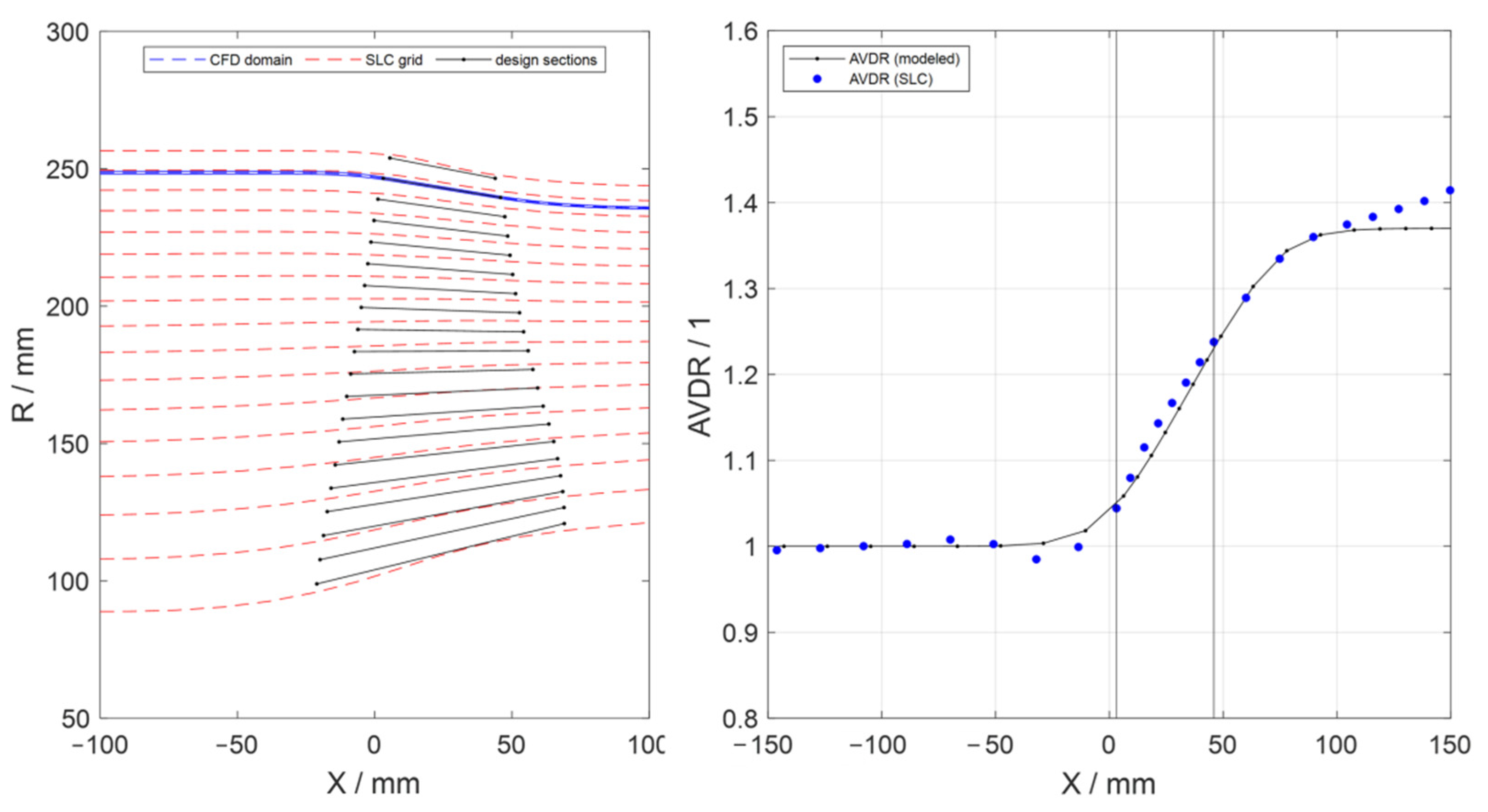
Based on the deformation results presented in Figure 18 and Figure 19, it can be assumed that for all actuation concepts, the highest deformations occur towards the rotor blade tip. Under this assumption, a preliminary Q3D simulation methodology for the detailed aerodynamic evaluation of the deformed profile performance is implemented in the design methodology. With the deformations highest towards the blade tip and the transonic and supersonic aerodynamic behavior highly sensitive towards small variations in the rotor geometry, a tip section is selected for the representative approach. Since the tip vortex dominates the surroundings of the blade tip, the second profile section at 95% blade height is chosen for the representative approach. The mean streamline for the creation of the simulation domain is derived from the design point SLC solution and interpolated on the reference blade section, defined preliminarily to the deformation study. In order to account for 3D effects, such as channel wall tapering, end wall boundary layer formation and compressibility effects, the AVDR distribution is derived from the reference flow data [3] and rebuilt with a hyperbolic modeling approach, introduced in [15]. The AVDR distribution is transformed into a CFD domain thickness distribution, which is then orthogonally added onto the mean streamline to create the radial boundaries of the simulation domain (Figure 20). With the simulation domain modeled, the deformed profile sections are projected onto the conical mean streamline within the blade row to finalize the Q3D simulation domain setup.
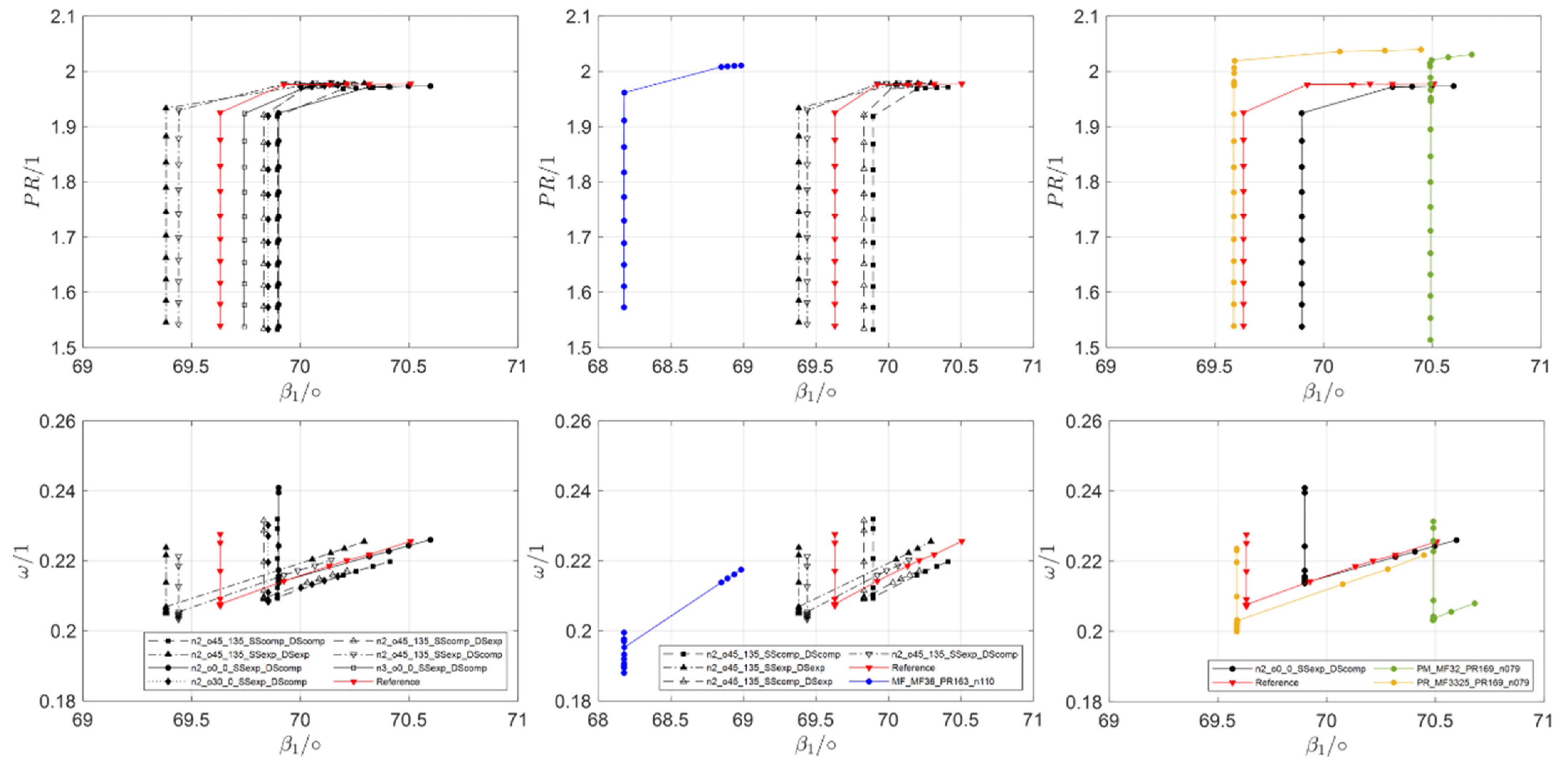
Analogous to the 3D-CFD stage simulation of the reference geometry, a k-ω turbulence model and a structured mesh is used. For the radial domain limits, a frictionless moving wall is assumed, while only one rotor section is simulated with periodic boundary conditions in circumferential direction. The Q3D performance analysis is applied to all actuation concepts and compared to the performance of the reference design for an initial evaluation of the aerodynamic effects of the piezoceramic actuation. Based on the first coupling step and according to Table 3, suitable actuation configurations are then compared to the performance of the aerodynamic target designs (Figure 21).
For the PM scenario, the mass flow reduction leads to a stronger staggering of the blade profiles, amplified by the reduced leading-edge camber angle due to the rearward relocation of the maximum camber. This also decreases suction-side curvature beyond the leading edge, as the profile cambering is now concentrated at the rear end of the profile, following the classic wedge-shaped profile designs for transonic and supersonic inflow conditions [29]. Compared to the actuator configuration, which yields the highest turning adaption, the stagger angle variation is negligible, while the leading-edge metal angle morphing visible in Figure 22 is mainly achieved through the increased camber angle at the leading edge. Although the blade profile turning is increased through the piezoceramic actuation, no increase in achievable pressure ratio is predicted in the Q3D simulative approach (Figure 21, middle). Only a slight shift of the unique incidence condition by less than 0.5° is visible, caused by the variation of the leading-edge metal angle. By considering the profile losses, it becomes evident that the effect of the increased blade turning is diminished by the elevated shock losses due to the higher suction-side curvature and the amplified pre-shock flow acceleration. Compared to the performance of the aerodynamic target shape, the inflow angle variation and the achievable variation in profile pressure ratio are too small to achieve the selected adaption scenario though shape morphing.
For the PR scenario, the required variation of the stagger angle is compensated by the leading-edge metal angle reduction due to the rearward shift of the maximum camber position. The twist of the target shape remains nearly constant compared to the reference geometry. Although the deformed profile sections (Figure 23) seem to fit the aerodynamic target shape better than those of the PM scenario, the required pressure rise is not achievable due to the increased shock losses (Figure 21). Additionally, the shift of the unique incidence condition is too high for the adaption scenario, where the mass flow, and therefore the unique incidence angle, should remain constant, as indicated by the performance of the aerodynamic target shape.
The aerodynamic simulation for the MF target design predicts a 1.5° decrease in unique incidence angle due to the increased design point mass flow. Additionally, the pressure ratio is increased compared to the reference design, which results from the lower profile loss values predicted by the Q3D simulation (Figure 21). Again, the alteration of the maximum camber position towards the trailing edge in combination with a turning reduction and therefore a reduction of the suction-side curvature has a positive influence on the shock-induced profile losses (Figure 24). The selected actuation concept shows a similar trend, with a slight increase in achievable pressure ratio and a 0.25° reduction of the unique incidence angle. However, the achievable deformations are too small to reach the pre-defined mass flow of the adaption scenario, indicating the requirement for an increased deformability of the reference blade design. For the selected actuation concept (nact = 2, o1 = 45°, o2 = 135°), the actuation mechanism can be switched from expansion to compression, reversing the deformation of the leading-edge metal angle. This increases the total achievable variation of the unique incidence angle to 0.52°, with a compressed actuation corresponding to a MF adaption scenario with reduced design point mass flow (Figure 21).
3. Conclusions and Discussion
This paper introduces a design methodology for the transformation of a conventional compressor rotor into a shape-adaptive system. By coupling aerodynamic design strategies with structural requirements and limits throughout the entire design process, shape morphing was applied to the well-researched NASA Rotor 67. In a simplified approach, the goal and potential of structural shape morphing for transonic compressor rotors was shown, mainly aiming at the improvement of the aerodynamic performance over the whole compressor operating range. Three possible morphing shape scenarios were chosen based on the reference design performance map, defining the starting point for the derivation of the aerodynamic shape morphing requirements. By coupling structural deformation limitations to the aerodynamic design process, explicitly considering the hub clamping of the rotor blade, an alignment of aerodynamic target design and structural feasible deformations was possible. The evaluation of shape adaption potential was done in two steps, with increasing accuracy. The first step evaluates the spanwise morphing of blade staggering and turning, compared to the aerodynamic requirements. In the second coupling step, the detailed aerodynamic behavior is considered in a representative Q3D simulative approach focusing on the blade’s tip region, where the largest deformations occur and where even small shape modifications lead to changes in the transonic aerodynamic performance.
As a result of the coupled analysis, it was observed that the incidence tolerance at the root region of the blade is very important for the reference design, since modifications through shape adaption in that region remain minimal due to the need for an attachment point for the blades. Because the largest deformations occur in the outer region of the blade, and this region is the one where the blade shock interaction massively influences blade performance, the highest potential for the application of shape morphing is identified there. The introduced actuation configurations showed the capability for controlling the off-design flow behavior in this region. However, as especially shown for the PM and PR scenarios, the shape morphing of the blade has to follow transonic profile design guidelines, such as the minimization of suction-side curvature, in order to reduce pre-shock flow acceleration and therefore shock-induced losses. Otherwise, the benefits of shape morphing are easily diminished.
The analysis of the morphed shapes and the iterative comparison with the aerodynamic target designs for the adaption scenarios showed that even though the analyzed morphing cases are not yet able to achieve the pre-defined performance, the influence of the spanwise variations in blade turning and leading-edge metal angle is apparent. With maximum profile turning variations between 0.2–1.8° and maximum leading-edge metal angle variations between 0.3° and 0.7°, the impact on the blade profile performance is observable in the representative Q3D simulation, mainly influencing the unique incidence condition near the blade tip and therefore indicating an effect for the full 3D blade performance. To increase the potential of the shape adaption technology, additional operational scenarios need to be considered, while maximizing and optimizing the feasible deformations in order to specifically exploit the blade shock interaction in the tip region of the rotor.
Finally, it must be noted that this analysis only presented a simplified view of the aerodynamic effects of shape adaption. In order to fully evaluate the morphing rotor’s performance and study the effects of additional changes, such as sweep or lean modifications, a full 3D analysis is necessary.
4. Outlook
Future work shall focus on the improvement and further development of the coupled design process for achieving an even tighter coupling, capable of including aerodynamic and structural parameters in the multidisciplinary design optimization loop. From a structural design point of view, more design variables and the use of unconventional materials, such as SMAs for the actuators and CFRP for the blades, should be considered for increasing morphing performance. Furthermore, the potential of redesigning the blade’s architecture at the root should also be considered in order to enlarge morphing effects in that region as well. Additionally, since the final phase of the coupling process focuses on the overall design of the blade and happens at a 3D level for both disciplines, detailed CFD aerodynamic performance analysis of the blades is necessary. These analyses will help bring effects resulting from 3D deformations into the morphing blade’s design process, into the aerodynamic performance evaluation and, as a result, into the coupled design optimization. Moreover, a further refinement of the coupling process itself and of the design parameters is necessary for enhancing the overall process. The coupling process will be extended to the reference blade design in order to design a blade shape that presents enough stiffness for a safe operation but also favors desirable deformations from the integrated actuation. Finally, in order to fully validate the method and simulative studies, blade prototypes shall be manufactured and tested. By considering all these factors, it will be possible to develop new morphing blade architectures that are capable of achieving better performance under design and off-design conditions.
Author Contributions
Introduction and methodology development, Z.M. and M.S.; detailed aerodynamic approach and development of aerodynamic tools, M.S.; detailed structural approach and development of structural analysis tools, Z.M.; writing—review and editing, Z.M. and M.S.; supervision, project administration and funding acquisition, J.F. and J.R. All authors have read and agreed to the published version of the manuscript.
Funding
This research received funding by the Deutsche Forschungsgemeinschaft (DFG, German Research Foundation) under Germany’s Excellence Strategy—EXC 2163/1- Sustainable and Energy Efficient Aviation—Project-ID 390881007.
Informed Consent Statement
Not applicable.
Acknowledgments
We would like to acknowledge the funding by the Deutsche Forschungsgemeinschaft (DFG, German Research Foundation) under Germany´s Excellence Strategy—EXC 2163/1- Sustainable and Energy Efficient Aviation—Project-ID 390881007.
Conflicts of Interest
The authors declare no known conflict of interest.
Appendix A

Table A1.
Summary of variables.
| Variable | Declaration |
|---|---|
| a, b | CSM design parameters |
| fc | maximum camber |
| fc(x) | dimensionless profile camber function |
| ft(x) | dimensionless profile thickness function |
| l | length |
| mass flow | |
| n | vortex law design parameter |
| nact | number of actuators |
| n1, n2 | class factors |
| o1, o2 | fiber orientation |
| xc | maximum camber position |
| y(x) | profile function value |
| y+ | dimensionless wall distance |
| C(x) | class function |
| F | force |
| KR | CSM thickness parameter |
| S(x) | shape function |
| Vθ | circumferential velocity |
| X | x-coordinate (machine axis) |
| αi | camber angle |
| ꞵi | relative flow angle |
| Δ | variation |
| Δβ | flow turning |
| Δφ | profile turning |
| iSA | shape adaption incidence |
| κi | metal angle |
| ꞷ | pressure loss coefficient |
| λ | stagger angle |
| Π | pressure ratio |
Table A2.
Summary of indexes.
| Index | Declaration |
|---|---|
| θ | circumferential |
| c | camber |
| t | tip |
| 1 | leading edge |
| 2 | trailing edge |
Table A3.
Abbreviations.
| Abbreviation | Extended Meaning |
|---|---|
| comp. | compression |
| exp. | expansion |
| ref | reference/original |
| ACP | Ansys Composite PrepPost |
| AVDR | Axial Velocity Density Ratio |
| CSM | Class Shape/Class Form Function |
| CFD | Computational Fluid Dynamics |
| CFRP | Carbon-Fiber-Reinforced Plastics |
| CMC | Ceramic Matrix Composite |
| DP | Design Point |
| FEA | Finite Element Analysis |
| IGV | Inlet Guide Vane |
| LE | Leading Edge |
| MF | Mass Flow |
| MFC | Macro-Fiber Composite |
| OGV | Outlet Guide Vane |
| PM | Performance Map |
| PR | Pressure Ratio |
| PS | Pressure Side |
| Q3D | Quasi-Three-Dimensional |
| SA | Shape Adaption |
| SLC | Streamline Curvature |
| SMA | Shape Memory Alloy |
| SS | Suction Side |
| TE | Trailing Edge |
| 3D | Three-Dimensional |
References
- Omar, H.; Kamel, A.; Alsanousi, M. Performance of Regenerative Gas Turbine Power Plant. Energy Power Eng. 2017, 9, 136–146. [Google Scholar] [CrossRef] [Green Version]
- Sehra, A.K.; Whitlow, W., Jr. Propulsion and power for 21st century aviation. Prog. Aerosp. Sci. 2004, 40, 199–235. [Google Scholar] [CrossRef]
- Antivachis, M.; Dietz, F.; Zwyssig, C.; Bortis, D.; Kolar, J.W. Novel High-Speed Turbo Compressor with Integrated Inverter for Fuel Cell Air Supply. Front. Mech. Eng. 2021, 6, 106. [Google Scholar] [CrossRef]
- Hünecke, K. Jet Engines: Fundamentals of Theory, Design and Operation—English Edition First Published in 1997 by Airlife Publishing; The Crowood Press Ltd.: Marlborough, UK, 2018. [Google Scholar]
- Torenbeek. Advanced Aircraft Design: Conceptual Design, Analysis and Optimization of Subsonic Civil Airplanes; John Wiley and Sons, Ltd.: West Sussex, UK, 2013. [Google Scholar]
- Gunn, E.J.; Brandvik, T.; Wilson, M.J. Fan-Intake Coupling with Conventional and Short Intakes. In Proceedings of the Aircraft Engine; Fans and Blowers; Marine; Wind Energy; Scholar Lecture. ASME Turbo Expo 2021: Turbomachinery Technical Conference and Exposition, Virtual, Online, 7–11 June 2021; American Society of Mechanical Engineers: New York, NY, USA, 2021; Volume 1. [Google Scholar]
- Voigt, J.; Jurke, K.N.; Schultz, J.; Römer, U.; Friedrichs, J. Quantifying Model Uncertainties and Sensitivities in Parallel Compressor Models. In Proceedings of the ASME Turbo Expo 2021: Turbomachinery Technical Conference and Exposition, Virtual, Online, 7–11 June 2021; American Society of Mechanical Engineers: New York, NY, USA, 2021. [Google Scholar]
- Okura, T. Materials for Aircraft Engines; Aircraft Propulsion ASEN 5063; 2015. Available online: https://www.colorado.edu/faculty/kantha/sites/default/files/attached-files/73549-116619_-_takehiro_okura_-_dec_17_2015_1027_am_-_asen_5063_2015_final_report_okura.pdf (accessed on 10 December 2021).
- Storm, R.; Skor, M.; Koch, L.D.; Benson, T.; Galica, C. Pushing the Envelope: A NASA Guide to Engines; NASA Glenn Research Center Office of Educational Programs in Cleveland: Celveleand, OH, USA, 2007. [Google Scholar]
- GE Fans Out on Testing of New GE9X Fan Blades: New Material and Design Improvements Drive High Aerodynamic Performance. Available online: https://www.geaviation.com/press-release/ge90-engine-family/ge-fans-out-testing-new-ge9x-fan-blades (accessed on 8 December 2021).
- Rolls-Royce Starts Manufacture of World’s Largest Fan Blades—Made of Composite Material—For Next-Generation UltraFan® Demonstrator. Available online: https://www.rolls-royce.com/media/press-releases/2020/11-02-2020-intelligentengine-rr-starts-manufacture-of-world-largest-fan-blades.aspx (accessed on 10 December 2021).
- Aungier, R.H. Axial-Flow Compressors. A Strategy for Aerodynamic Design and Analysis; American Society of Mechanical Engineers: New York, NY, USA, 2003. [Google Scholar]
- Joos, F. Aerodynamik Axialer Turbokompressoren, 1st ed.; Springer Vieweg: Wiesbaden, Germany, 2020. [Google Scholar]
- Bross, S.; Stark, U. Entwicklung neuer Schaufelgitter aus Profilen variabler Geometrie zum Einsatz in Leiträdern drallgeregelter Turbomaschinen—Teil II. Forsch. Im Ing. 1994, 60, 120–132. [Google Scholar] [CrossRef]
- Stark, U. Ebene Verdichtergitter in Quasizweidimensionaler Unterschallströmung; VDI-Forschungsheft/Verein Deutscher Ingenieure (641/87): Düsseldorf, Germany, 1987; pp. 1–64. [Google Scholar]
- Teßmer, J.; Montano Rejas, Z. Smart Rotors for Cost Efficient Wind Turbines. In Energie: Herausforderungen der Energiewende; Deutsche Physikalische Gesellschaft, Frühjahrstagung des Arbeitskreises Energie: Münster, Gernamy, 2017; pp. 98–109. ISBN 978-3-9818197-2-4. [Google Scholar]
- Suman, A.; Fortini, A.; Merlin, M. A Shape Memory Alloy-based Morphing Axial Fan Blade: Functional Characterization and Perspectives. Energy Procedia 2015, 82, 273–279. [Google Scholar] [CrossRef] [Green Version]
- Kalow, S.; Keimer, R.; van de Kamp, B.; Riemenschneider, J. Next Generation Active Twist Helicopter Rotor Blade—Simulated Results Validated by Experimental Investigation. In Proceedings of the 45th European Rotorcraft Forum 2019, Warsaw, Poland, 16–19 September 2019. [Google Scholar]
- Krone, J.H.; Huxdorf, O.; Riemenschneider, J.; Monner, H.P.; Schur, F.; Friedrichs, J.; Wiedemann, M. Experimental investigation and design of a shape-variable compressor cascade. CEAS Aeronaut. J. 2016, 8, 105–127. [Google Scholar] [CrossRef]
- Smart Material: Macro Fiber Composite—MFC. Available online: https://www.smart-material.com/media/Datasheets/MFC_V2.4-datasheet-web.pdf (accessed on 20 May 2021).
- CompActive. Planar Bending Actuator—Technology in Motion. Available online: https://compactive.de/technology/ (accessed on 20 May 2021).
- Strazisar, A.J.; Hathaway, M.D.; Suder, K.L.; Wood, J.R. Laser Anemometer Measurements in a Transonic Axial-Flow Fan Rotor; NASA: Cleveland, OH, USA, 1989. [Google Scholar]
- Reis, A. Validation of NASA Rotor 67 with OpenFOAM’s Transonic Density-Based Solver; Faculdade de Ciencias e Tecnologia: Faro, Portugal, 2013. [Google Scholar]
- Schlichting, H.; Truckenbrodt, E.A. Aerodynamik des Flugzeuges. Erster Band. Grundlagen aus der Strömungsmechanik, Aerodynamik des Tragflügels (Teil I); Springer: Berlin/Heidelberg, Germany, 2001. [Google Scholar]
- Kulfan, B.; Bussoletti, J. Fundamental Parameteric Geometry Representations for Aircraft Component Shapes. In Proceedings of the 11th AIAA/ISSMO Multidisciplinary Analysis and Optimization Conference, Portsmouth, NH, USA, 6–8 September 2006. [Google Scholar] [CrossRef] [Green Version]
- Bräunling, W.J. Flugzeugtriebwerke: Grundlagen, Aero-Thermodynamik, Ideale und Reale Kreisprozesse, Thermische Turbomaschinen, Komponenten, Emissionen und Systeme, 4th ed.; Springer Vieweg (VDI Book): Berlin/Heidelberg, Germany, 2015. [Google Scholar]
- Seidler, M.; Sivamoorthy, K.; Friedrichs, J. Introduction of a Streamline Curvature Design Methodology for the Vortex Design of Shape Adaptive Compressor Blading. In Proceedings of the 14th European Conference on Turbomachinery Fluid Dynamics and Thermodynamics, Gdansk, Poland, 12–16 April 2021. [Google Scholar]
- Johnsen, I.A.; Bullock, R.O. (Eds.) Aerodynamic Design of Axial Flow Compressors; NASA: Washington, DC, USA, 1965. [Google Scholar]
- Fottner, L.; Lichtfunss, H.J. Design of Transonic Compressor Cascades for Minimal Shock Losses and Comparison with Test Results; Defense Technical Information Center: Fort Belvoir, VA, USA, 1983; pp. 13–21. [Google Scholar]
- Seidler, M.; Friedrichs, J. Introduction of an improved axial compressor profile shape modelling approach for increased flexibility in transonic profile design. In Proceedings of the Global Power and Propulsion Society, Xi’an, China, 18–20 October 2021. in press. [Google Scholar]
- ANSYS. Materials Data for Simulation. 2020. Available online: https://www.ansys.com/content/dam/product/materials/materials-data-simulation.pdf (accessed on 18 December 2021).
- Pavlenko, D.; Dvirnyk, Y.; Przysowa, R. Advanced Materials and Technologies for Compressor Blades of Small Turbofan Engines. Aerospace 2020, 8, 1. [Google Scholar] [CrossRef]
- Okura, T. Materials for Aircraft Engines; Aircraft Propulsion ASEN 5063; 2015. Available online: https://www.colorado.edu/faculty/kantha/sites/default/files/attached-files/73549-116618_-_takehiro_okura_-_dec_17_2015_1025_am_-_materials_for_aircraft_engines_presentation_takehiro_okura.pdf (accessed on 8 December 2021).
Figure 1.
Overview of the coupling methodology design loop.

Figure 2.
Exemplary actuation configurations for the NASA 67 compressor rotor blade (grey) with the pressure sides on the right and the suction sides on the left. Top: one large surface actuator per side (blue and green); middle: one large surface actuator on the suction side (orange) and two smaller actuators on the pressure side (green and blue); bottom: four smaller actuators on each side (colored surfaces).

Figure 3.
Simulated speed line for the NASA 67 front stage for design speed, with the literature design point (DP, red), a performance map adaption well beyond the simulated surge margin (PM, green), a mass flow adaption (MF, blue) and a variation of the pressure ratio (PR, yellow).
Figure 3.
Simulated speed line for the NASA 67 front stage for design speed, with the literature design point (DP, red), a performance map adaption well beyond the simulated surge margin (PM, green), a mass flow adaption (MF, blue) and a variation of the pressure ratio (PR, yellow).

Figure 4.
Calculation domain and grid for the SLC calculation with rotor, rotor reference design sections and stator geometry in the meridional plane.
Figure 4.
Calculation domain and grid for the SLC calculation with rotor, rotor reference design sections and stator geometry in the meridional plane.

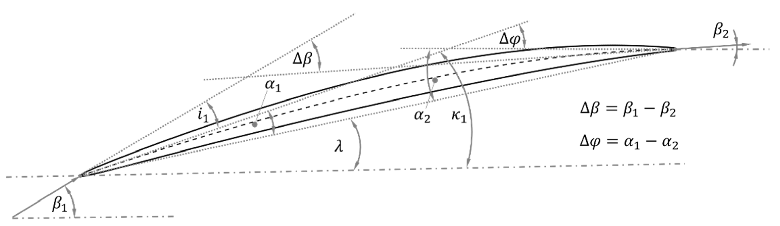
Figure 5.
Schematic overview of flow and blade angle definitions, following [28].
Figure 5.
Schematic overview of flow and blade angle definitions, following [28].

Figure 6.
Exemplary decomposition of an aerodynamic profile section (b) into the camber modelling, defined by the maximum camber fc, its position xc (a) and the thickness modelling with the free parameter KR (c).
Figure 6.
Exemplary decomposition of an aerodynamic profile section (b) into the camber modelling, defined by the maximum camber fc, its position xc (a) and the thickness modelling with the free parameter KR (c).

Figure 7.
Profile turning Δφ variation (a) and leading-edge camber angle α1 variations (b) for a relative adaption of fc and its chordwise position xc in relation to the reference parameters fc,ref and xc,ref.
Figure 7.
Profile turning Δφ variation (a) and leading-edge camber angle α1 variations (b) for a relative adaption of fc and its chordwise position xc in relation to the reference parameters fc,ref and xc,ref.

Figure 8.
Exemplary wireframe structures and derived CAD models for the structural design based on the aerodynamic design streamline sections with different actuator configurations. (a) Matlab blade contour basis model following SLC aerodynamic curves, (b) and (c) Matlab blade contour models with two possible actuator configurations – the blue lines representing the actuator limits for the pressure side and the red lines those for the suction side, (d) CAD basis geometry with streamlines and actuator limits, (e) CAD solid blade body model with actuators limits for an exemplary configuration.

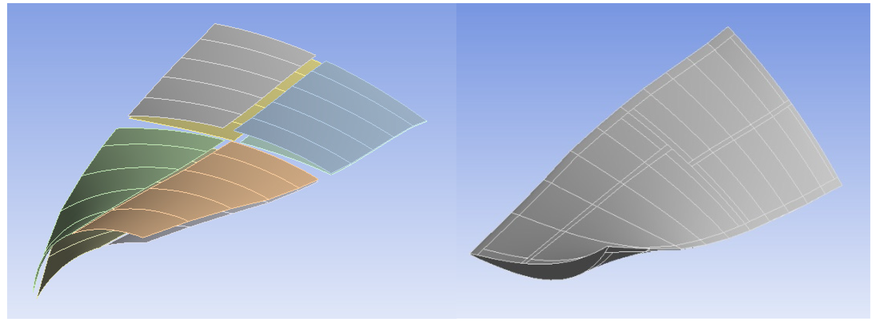
Figure 9.
Blade architecture example, left: actuators set with suction side on top and pressure side at bottom (without blade); right: blade’s body with markings for actuators’ mounting positions.
Figure 9.
Blade architecture example, left: actuators set with suction side on top and pressure side at bottom (without blade); right: blade’s body with markings for actuators’ mounting positions.

Figure 10.
Schematic representation of an MFC actuator structure—Adapted with permission from ref. [20], Smart Material Corp.
Figure 10.
Schematic representation of an MFC actuator structure—Adapted with permission from ref. [20], Smart Material Corp.

Figure 11.
SMA actuators (left) and working principle (right). l and b indicate the size of the actuator, s the deformation path, F the load carrying capacity and R the electric resistance applied to the actuator as a source of heat—Adapted with permission from ref. [21], CompActive.
Figure 11.
SMA actuators (left) and working principle (right). l and b indicate the size of the actuator, s the deformation path, F the load carrying capacity and R the electric resistance applied to the actuator as a source of heat—Adapted with permission from ref. [21], CompActive.

Figure 12.
ACP model for MFC actuators. The green surfaces represent the actuating surfaces, and the green arrows represent the fiber direction, which corresponds with the actuation direction.
Figure 12.
ACP model for MFC actuators. The green surfaces represent the actuating surfaces, and the green arrows represent the fiber direction, which corresponds with the actuation direction.

Figure 13.
Bonded contact illustration for one actuator. (a) Blade body with highlighted actuating surfaces for one actuator, (b) Contact actuator surfaces for exemplary actuator, (c) Target body surfaces on blade for exemplary actuator.
Figure 13.
Bonded contact illustration for one actuator. (a) Blade body with highlighted actuating surfaces for one actuator, (b) Contact actuator surfaces for exemplary actuator, (c) Target body surfaces on blade for exemplary actuator.

Figure 14.
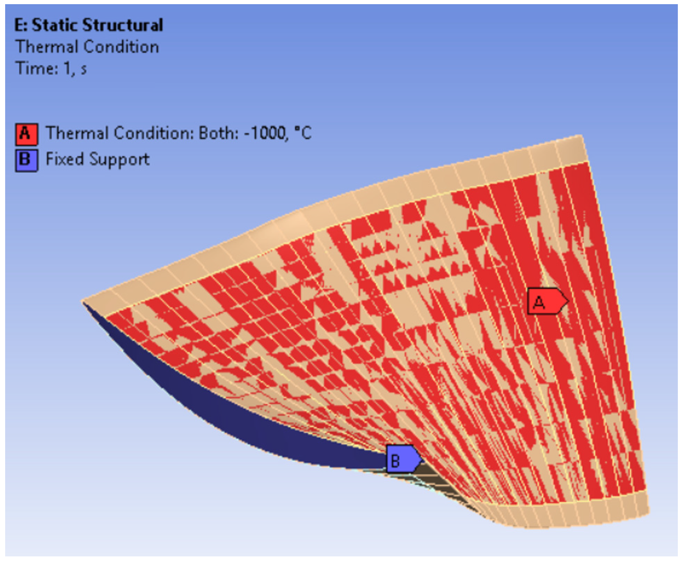
Boundary conditions for the model of the morphing blade. A, in red, shows the embedded actuator surface and the area to which the thermal analogy boundary constraint is applied. B, in blue, shows the fixed support constraint and represents the behavior of the blade at its root.
Figure 14.
Boundary conditions for the model of the morphing blade. A, in red, shows the embedded actuator surface and the area to which the thermal analogy boundary constraint is applied. B, in blue, shows the fixed support constraint and represents the behavior of the blade at its root.

Figure 15.
Ansys Workbench static structural analysis results for deformation. The black cable structure represents the undeformed blade.
Figure 15.
Ansys Workbench static structural analysis results for deformation. The black cable structure represents the undeformed blade.

Figure 16.
Ansys Workbench static structural analysis results for deformation at the original aerodynamic sections. These sections enable the coupling with aerodynamics. The black cable structure represents the undeformed blade.
Figure 16.
Ansys Workbench static structural analysis results for deformation at the original aerodynamic sections. These sections enable the coupling with aerodynamics. The black cable structure represents the undeformed blade.

Figure 17.
Qualitative representation of possible morphing shapes. The black wireframe represents the undeformed blade. On the top left, a larger camber modification can be observed; the bottom left shows a change in the twist angle, and the right image shows a displacement in the position of the maximum camber.

Figure 18.
Comparison of the flow deflection angle variations in the blade profile turning angle morphing for different vortex designs and actuation concepts, separated according to the selected adaption scenario (left: PM, middle: PR, right: MF).
Figure 18.
Comparison of the flow deflection angle variations in the blade profile turning angle morphing for different vortex designs and actuation concepts, separated according to the selected adaption scenario (left: PM, middle: PR, right: MF).

Figure 19.
Comparison of the inflow angle variations in the leading-edge metal angle morphing for different vortex designs and actuation concepts, separated according to the selected adaption scenario (left: PM, middle: PR, right: MF).
Figure 19.
Comparison of the inflow angle variations in the leading-edge metal angle morphing for different vortex designs and actuation concepts, separated according to the selected adaption scenario (left: PM, middle: PR, right: MF).

Figure 20.
Q3D calculation domain for the representative evaluation of Section 2 in relation to the streamlines of the design point geometry and the pre-defined reference sections (left) and the comparison of the SLC AVDR with the hyperbolic remodeling approach (right).
Figure 20.
Q3D calculation domain for the representative evaluation of Section 2 in relation to the streamlines of the design point geometry and the pre-defined reference sections (left) and the comparison of the SLC AVDR with the hyperbolic remodeling approach (right).

Figure 21.
Representative Q3D evaluation (Section 2) of the deformed profile sections (left), comparison of PM and PR target design performances with selected actuation configuration (middle) and comparison of MF target design with selected actuation concept (right).
Figure 21.
Representative Q3D evaluation (Section 2) of the deformed profile sections (left), comparison of PM and PR target design performances with selected actuation configuration (middle) and comparison of MF target design with selected actuation concept (right).

Figure 22.
Comparison of target design and morphed shape to the reference design (Section 2, PM scenario, profile staggering relative to reference design).
Figure 22.
Comparison of target design and morphed shape to the reference design (Section 2, PM scenario, profile staggering relative to reference design).

Figure 23.
Comparison of target design and morphed shape to the reference design (Section 2, PR scenario, profile staggering relative to reference design).
Figure 23.
Comparison of target design and morphed shape to the reference design (Section 2, PR scenario, profile staggering relative to reference design).

Figure 24.
Comparison of target design and morphed shape to the reference design (Section 2, MF scenario, profile staggering relative to reference design).
Figure 24.
Comparison of target design and morphed shape to the reference design (Section 2, MF scenario, profile staggering relative to reference design).

Table 1.
Material properties for the exemplary compressor blade—Titanium Alloy [31].
Table 1.
Material properties for the exemplary compressor blade—Titanium Alloy [31].
| Property | Value | Unit |
|---|---|---|
| Density | 4620 | kg/m3 |
| Young’s Modulus | 9.6 × 10¹⁰ | Pa |
| Poisson’s Ratio | 0.36 | - |
| Shear Modulus | 3.5294 × 10¹⁰ | Pa |
| Tensile Yield Strength | 9.3 × 10⁸ | Pa |
Table 2.
Material properties for exemplary MFC piezoelectric actuators [20].
Table 2.
Material properties for exemplary MFC piezoelectric actuators [20].
| Property | Value | Unit |
|---|---|---|
| Density | 4700 | kg/m3 |
| Young’s Modulus X | 3.00 × 10¹⁰ | Pa |
| Young’s Modulus Y | 1.55 × 10¹⁰ | Pa |
| Young’s Modulus Z | 1.55 × 10¹⁰ | Pa |
| Poisson’s Ratio XY | 0.35 | - |
| Poisson’s Ratio YZ | 0.4 | - |
| Poisson’s Ratio XZ | 0.35 | - |
| Shear Modulus XY | 1.07 × 10¹⁰ | Pa |
| Shear Modulus YZ | 5.70 × 10⁹ | Pa |
| Shear Modulus XZ | 1.07 × 10¹⁰ | Pa |
| Coef. of Thermal Expansion X | 8.36 × 10⁻⁷ | 1/°C |
| Coef. of Thermal Expansion Y | −3.96 × 10⁻⁷ | 1/°C |
| Coef. of Thermal Expansion Z | −3.96 × 10⁻⁷ | 1/°C |
| Tensile Yield Strength | 9.3 × 10⁸ | Pa |
Table 3.
Overview of selected actuation concepts and aerodynamic design parameters for exemplary morphing scenarios.
Table 3.
Overview of selected actuation concepts and aerodynamic design parameters for exemplary morphing scenarios.
| Scenario | Aerodynamic Design | Actuation Configuration |
|---|---|---|
| PM | Π = 1.69, = 32 kg/s, n = 0.79 | nact = 2, o1 = 0°, o2 = 0°, SS = exp, DS = comp |
| PR | Π = 1.69, = 33.25 kg/s, n = 0.79 | nact = 2, o1 = 0°, o2 = 0°, SS = exp, DS = comp |
| MF | Π = 1.63, = 36 kg/s, n = 1.1 | nact = 2, o1 = 45°, o2 = 135°, SS = exp, DS = exp |
Publisher’s Note: MDPI stays neutral with regard to jurisdictional claims in published maps and institutional affiliations. |
© 2022 by the authors. Licensee MDPI, Basel, Switzerland. This article is an open access article distributed under the terms and conditions of the Creative Commons Attribution (CC BY) license (https://creativecommons.org/licenses/by/4.0/).
Share and Cite
MDPI and ACS Style
Montano, Z.; Seidler, M.; Riemenschneider, J.; Friedrichs, J. A Coupling Method for the Design of Shape-Adaptive Compressor Blades. Appl. Mech. 2022, 3, 182-209. https://0-doi-org.brum.beds.ac.uk/10.3390/applmech3010014
AMA Style
Montano Z, Seidler M, Riemenschneider J, Friedrichs J. A Coupling Method for the Design of Shape-Adaptive Compressor Blades. Applied Mechanics. 2022; 3(1):182-209. https://0-doi-org.brum.beds.ac.uk/10.3390/applmech3010014
Chicago/Turabian StyleMontano, Zhuzhell, Marcel Seidler, Johannes Riemenschneider, and Jens Friedrichs. 2022. "A Coupling Method for the Design of Shape-Adaptive Compressor Blades" Applied Mechanics 3, no. 1: 182-209. https://0-doi-org.brum.beds.ac.uk/10.3390/applmech3010014