Green Forging of Titanium and Titanium Alloys by Using the Carbon Supersaturated SKD11 Dies


1
Graduate School of Engineering, University of Toyama, Toyama 930-8555, Japan
2
Surface Engineering Design Laboratory, Shibaura Institute of Technology, Tokyo 144-0045, Japan
3
Faculty of Engineering, University of Toyama, Toyama 930-8555, Japan
*
Author to whom correspondence should be addressed.
Appl. Mech. 2022, 3(3), 724-739; https://0-doi-org.brum.beds.ac.uk/10.3390/applmech3030043
Submission received: 31 May 2022
/
Revised: 14 June 2022
/
Accepted: 17 June 2022
/
Published: 23 June 2022
(This article belongs to the Special Issue Fracture Mechanics and Durability of Engineering Materials)
Abstract
:The carbon-supersaturated SKD11 punch was proposed as a green, or, a galling-free, long-life and low energy-consuming forging tool of pure titanium and β-titanium alloy that works with low friction and less work hardening and without galling. The reduction in thickness was increased up to 50% to investigate the friction process on the contact interface and the work-hardening behavior. The nitrogen-supersaturated SKD11 punch was utilized as a reference tool for this forging experiment. Three-dimensional finite element analysis was employed to derive the regression curve between the contact interface width and the friction coefficient. The friction coefficient was estimated in forging the pure titanium wires by using the regression curves. The work-hardening process was analyzed by the hardness mapping on the cross-section of forged wires. The SEM-EDX analysis on the contact interface proved that no adhesion of fresh metallic titanium and titanium oxide debris was seen on the interface between the carbon-supersaturated SKD11 punch and the titanium work. In particular, the work hardening is suppressed without shear localization in forging the β-titanium. Finally, the uniform carbon layer was derived from the supersaturated carbon solute from the punch matrix and wrought as a friction film on the contact interface to reduce the friction and the work hardening as well as suppress the chemical galling. This in situ carbon lubrication must be essential in green forging to highly qualify the titanium and titanium alloy products and to prolong the punch-and-die lives in practical operation.
1. Introduction
Titanium and titanium alloys have been highlighted as a structural member of aircrafts [1], a biomedical tool [2], sporting goods [3,4], a mechanical part of watches, robots, MEMS [5,6], etc. Their high strength and light-weight are all attractive to mechanical designers but their difficulty in metal forming hinders this possibility. In particular, their fresh surfaces appear during their forging and forge-stamping processes and often adhere to die surfaces [7]. This mass adhesion or chemical galling to the die and tool significantly increases the friction coefficient on the contact interface. In addition to this high frictional state, the high work hardening of those titanium works often lowers the reduction in thickness to 15–20% and requires thermal annealing as the intermediate step to relax the hardened works before further forging steps.
This difficulty was solved by the innovative change of die substrate materials. DLC and ceramic coating were selected as the first candidate to lower the friction and wear in forging. As reported in [8], those coatings had a risk of galling even in the cold forging of pure titanium. In particular, a high friction coefficient was experienced even in the tribological testing for TiN and TiCN-coated discs against the pure titanium balls by ball on disc test. The surface modification, such as plasma nitriding, is the second approach to harden the stainless steel and tool steel die substrates at 673 K without the formation of iron and chromium nitrides [9]. Its average hardness in the thick nitrided layer of 50 µm reached 1500 HV after plasma nitriding at 673 K for 14.4 ks (or 4 h) [10]. This high hardness and higher nitrogen solute content than 4 mass% of nitrogen supersaturated (Ns) dies are attractive characteristics for improving the wear and adhesion toughness, even during the forging process of titanium and titanium alloys. The third approach is plasma carburizing at a low holding temperature. As stated in [7], the iron and chromium carbides were formed as precipitates in the stainless steel and tool steel die substrate when plasma carburizing at a higher temperature than 753 K during a longer period of time in a similar manner to high temperature plasma nitriding to synthesize the nitride precipitates. The plasma carburizing process at 673 K for 14.4 ks was proposed as a super-carburizing process into the stainless steels [11] and tool steels [12] without the formation of any carbides. During the forging process, the supersaturated carbon solute isolates itself from the substrate matrix and forms a carbon-stripe friction film on the contact interface between the carbon supersaturated (Cs) die substate and the work materials. Owing to this in situ formation of friction films onto the contact interface, no adhesion of work materials or chemical galling to die surfaces occurs to continue the forging process even under the high reduction in thickness [13,14]. An average hardness higher than 1200 HV in the carburized layer and this in situ solid lubrication by isolated carbon solutes is also less attractive for the forging of titanium and titanium alloys.
In the present paper, these two Ns- and Cs-SKD11 punches are, respectively, prepared by low temperature plasma nitriding and carburizing processes for upset-forging experiments up to the high reduction in thickness. The β-SiC-coated SiC substrate is commonly utilized as a die. The pure titanium and β-titanium alloy wires with the diameter of 3.0 mm are employed to investigate the work-hardening process by high-reduction forging experiments. The friction on the contact interface is estimated by the inverse analysis. The finite element analysis (FEA) is utilized to accurately estimate the friction coefficient on the contact interface between the Ns-SKD11/Cs-SKD11 punch and the titanium work. The regression relation between the wire and contact interface widths is simulated by FEA in the function of the friction coefficient (μ). The actual friction coefficient is determined from this regression curve, provided that the condition of the experimentally measured widths is fulfilled. A hardness mapping technique is employed to analyze the work-hardening behavior at the reduction in work thickness from 10 to 50%. The interface analysis was performed to investigate the adhesion of the fresh work materials onto the contact interface. Through these precise analyses, the Cs-SKD11 punch is proposed as a green forging tool of titanium and titanium alloy works with low friction, less work hardening and without chemical galling.
2. Experimental Procedure
2.1. Preparation of Plasma Processed Punches
SKD11 punches were, respectively, plasma nitrided and carburized to prepare the hardened SKD11 punch with nitrogen and carbon supersaturation. Table 1 lists the plasma processing conditions for nitriding and carburizing, respectively. The essential difference between the two processes lies in the source-gas mixture. The nitrogen and hydrogen gas mixture with the flow rate ratio of 160 mL/min for nitrogen and 30 mL/min for hydrogen was utilized to make plasma nitriding. The population of NH radicals and nitrogen ions was intensified under this gas flow mixture after the plasma diagnosis in [15]. The methane, hydrogen and argon mixture with the flow rate ratio of 20 mL/min both for methane and hydrogen and 160 mL/min for argon was used to make plasma carburizing. The population of CH radicals and carbon ions was also intensified under this condition after the plasma diagnosis in [11]. In both cases, the RF-DC plasma processing system was used for both nitriding and carburizing.
2.2. Work Materials
Pure titanium of industrial grade I and the β-phase titanium alloy wires with the diameter of 3.0 mm and length of 10 mm were employed as a work material in the forging experiment. The chemical composition of pure titanium wires consists of hydrogen by 0.0012 mass%, oxygen by 0.097 mass%, nitrogen by 0.007 mass%, iron by 0.042 mass%, carbon by 0.007 mass%, and titanium for balance. The chemical compositions of β-titanium wires were listed in the following; e.g., 0.01 mass% carbon, 3.1 mass% aluminum, 14.6 mass% vanadium, 0.21 mass% iron, 3.2 mass% tin, 2.9 mass% chromium, 0.01 mass% nitrogen, 1300 ppm oxygen, 40 ppm hydrogen, and titanium in balance.
2.3. Forging System
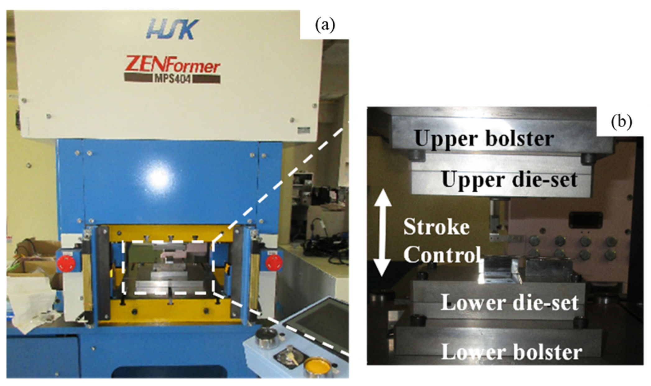
A computer numerical control (CNC) stamper (Hoden Precision, Co., Ltd., Kanagawa, Japan) was utilized for upsetting down to the specified stroke in reduction, as shown in Figure 1a. In this stamper, four unit motors wrought independently to compensate for eccentric loading. The load cell was embedded to the lower die set to monitor the applied load history. The plasma-processed SKD11 punch was inserted into the upper cassette die and β-SiC-coated SiC die was cemented into the lower die set, as depicted in Figure 1b. Both the upper and the lower cassette dies were fixed into each bolster of the CNC stamper. In practical operation, the stroke was lowered at a constant velocity of 0.1 mm/s down to the specified minimum stroke (δm), held for 1 s, and then moved up to the original position at the same velocity. This δm was varied for each reduction in the thickness of the titanium wires. In the following forging experiments, the β-SiC-coated SiC die was commonly utilized since the carbon supersaturated β-SiC coating had anti-galling capacity against the titanium and titanium alloy works in forging [16].
2.4. Finite Element Forging Analysis
The friction coefficient on the contact interface between the forged titanium work and the Ns-/Cs-SKD11 punch was estimated by the inverse analysis with the aid of FEA. First, the DEFORM-3D was utilized to make the three-dimensional upsetting simulation of titanium and β-titanium wires by varying the friction coefficient (μ). Half of the titanium wire was discretized into a finite element model. The friction conditions with the specified m were assumed on the contact interface between the rigid punch and die and the model. The other surface areas of the model were subjected to the stress-free boundary conditions. The bilinear stress–strain relationship was utilized as a constitutive equation of pure titanium and β-titanium works, respectively.
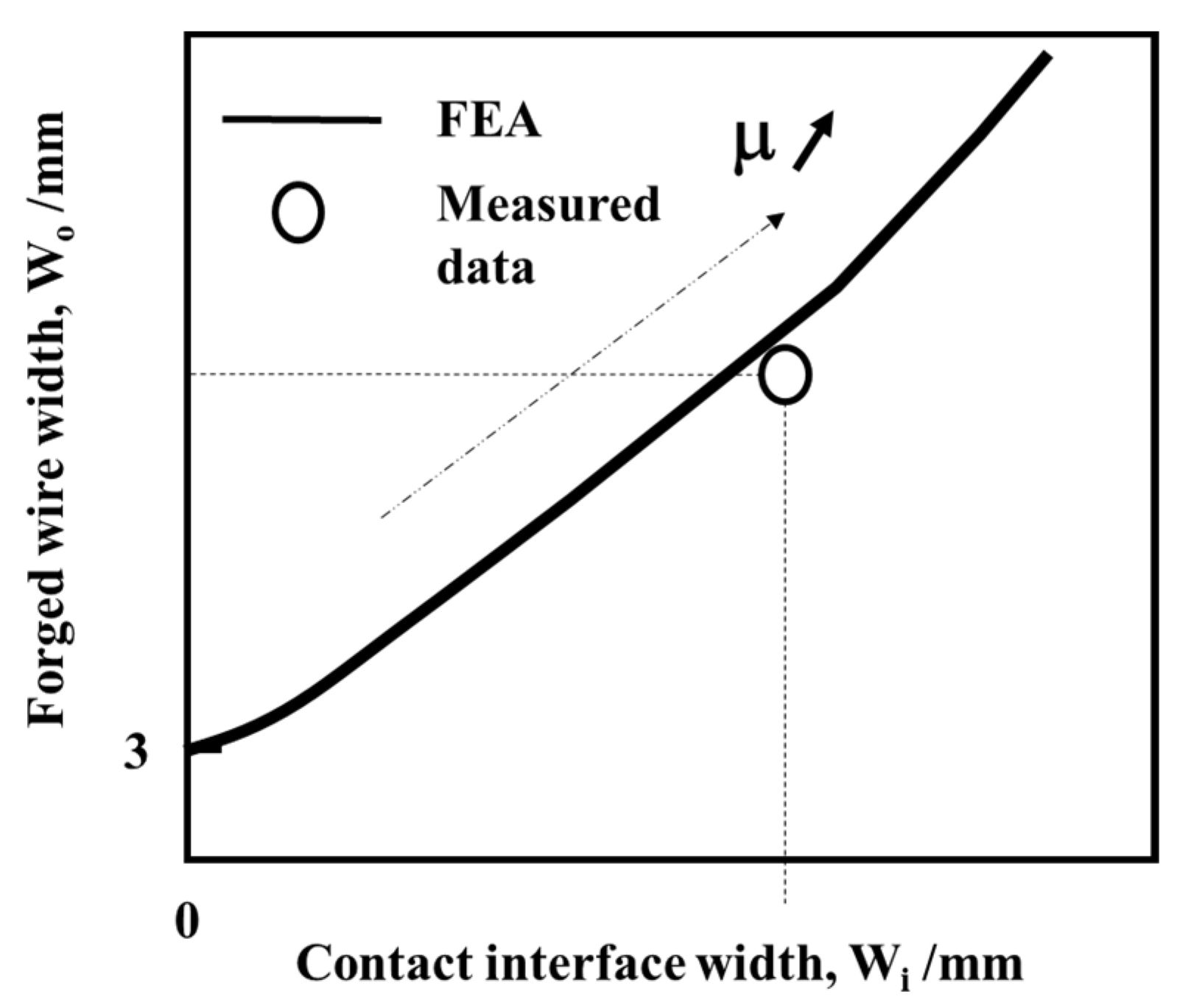
When μ >> 1, the contact interface with (Wc) and the forged wire width (Wo) become minimum. With a decreasing μ, both widths monotonously increase with the increasing reduction in thickness. In the inverse analysis, Wc and Wo are calculated by FEA at the specified reduction in thickness in the function of m. The solid line in Figure 2 denotes the theoretical variation of Wc (μ) and Wo (μ0) in the function of μ. At the same reduction in thickness, the experimentally measured Wc and Wo were plotted onto the calculated regression curve in Figure 2 to estimate the actual friction coefficient (μ0) on the contact interface by Wc (μ0) ~ Wc and Wo (μ0) ~ Wo.
In this inverse FEA, the plastic strain tensor distribution at each reduction in thickness was incrementally calculated to theoretically describe the work-hardening process of work by the simulated equivalent plastic strain distribution.
2.5. Hardness Mapping
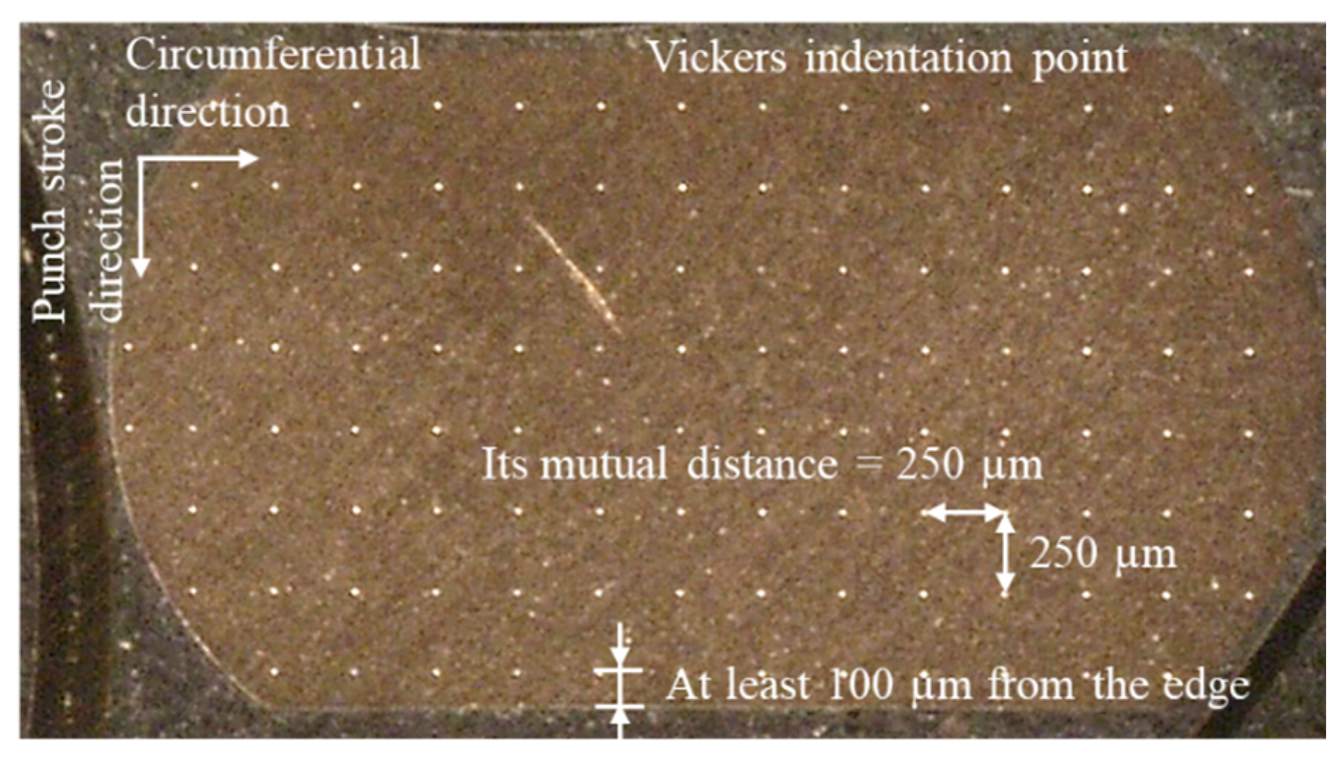
The specimens for hardness mapping were prepared from the forged test-pieces as follows. The forged specimens at each reduction in thickness were cut by wire cutting machine in the circumferential direction and embedded in resin at 453 K (or 180 °C). The cross-section of the embedded specimens for hardness testing was polished by the abrasive paper from #80 to #4000 and finally buffed by using the alumina abrasive particles with a size of 0.3 µm. The hardness tester (HM-100; Mitsutoyo, Co., Ltd.; Kanagawa, Japan) was employed to measure the hardness distribution on the cross-section of the specimens. The applied load for this hardness testing was held constant by 1 N (or 0.1 kgf) for 10 s. Figure 3 shows how to make an indentation at each measurement point of hardness. Its mutual distance was 250 μm in normal indentation onto the cross-section of forged wires. This distance was reduced to 100 μm in minimum for the indentation at the vicinity of test-piece edges. The whole measured hardness data were edited into a hardness map in the color contour-lines with the hardness interval of 25 HV.
3. Experimental Results
The upsetting behavior was described by the measurement of the forged titanium and β-titanium wire widths and contact interface widths for each reduction in thickness (r). The frictional behavior was monitored in the variation of bulging deformation with an increasing r. The actual friction coefficient at r = 50% was estimated by the inverse analysis with the aid of FEA. The shear-band formation and work-hardening behavior was analyzed by the hardness mapping technique. The galling behavior was described through the SEM-EDX analysis on the contact interface between the forged titanium work and the punch after continuously upsetting up to r = 50% in 20 shots.
3.1. Upsetting Behavior of Titanium and β-Titanium Wires
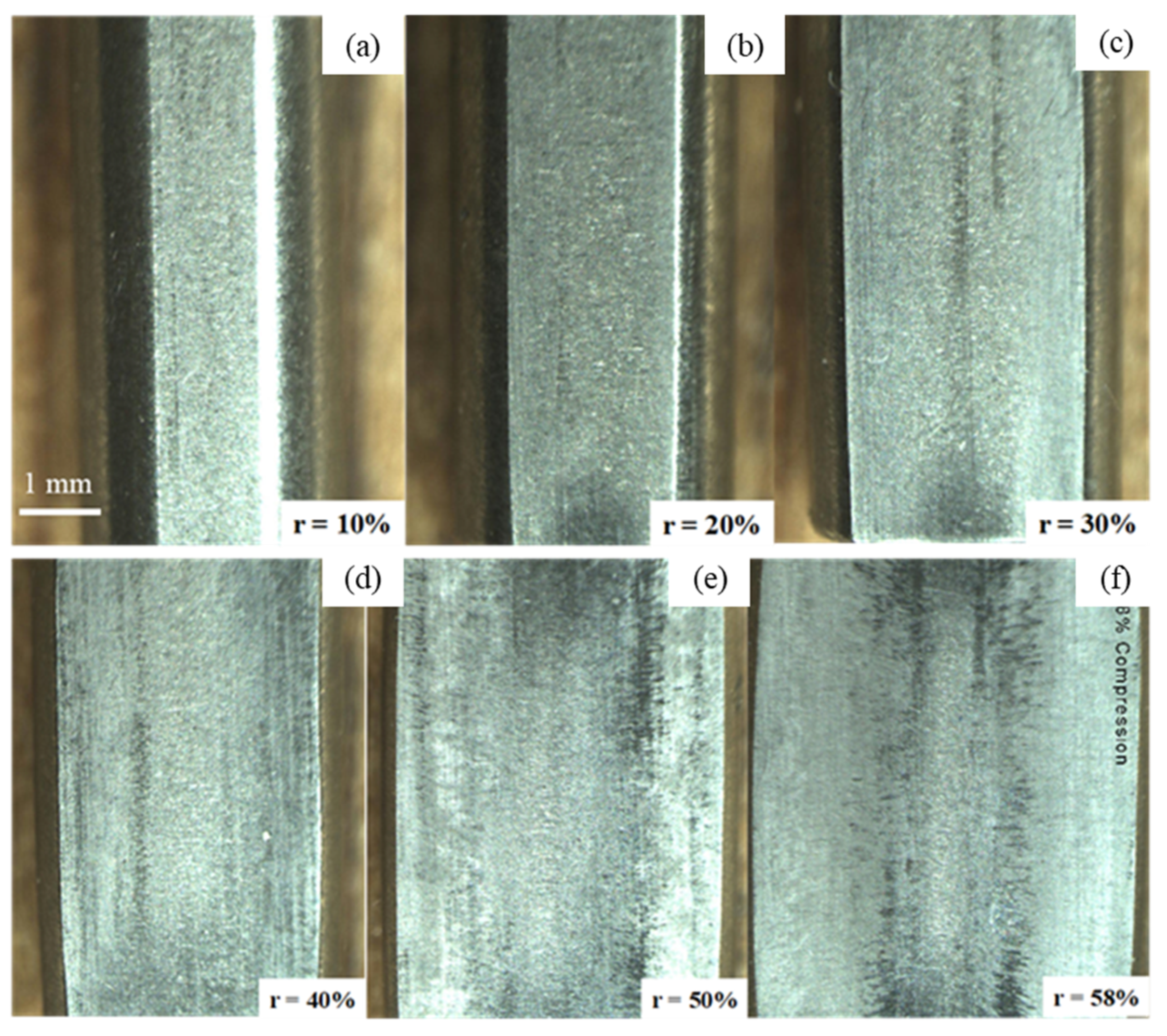
The stroke was controlled to move down in every 10% reduction in thickness at this upsetting experiment. Figure 4 depicts the variation of β-titanium wire width with increasing r. At r = 0%, the initial wire width (Wo) was 3 mm and the contact interface width (Wc) was zero. When r = 10 %, the wire was mainly compressed in the axial direction; Wo > Wc. When r > 20%, the flattening process overwhelmed the total wire deformation. For r > 30%, Wc approached to Wo; Wc ~ Wo at r = 50%. That is, no bulging deformation took place during the upsetting of β-titanium work for r > 50%.
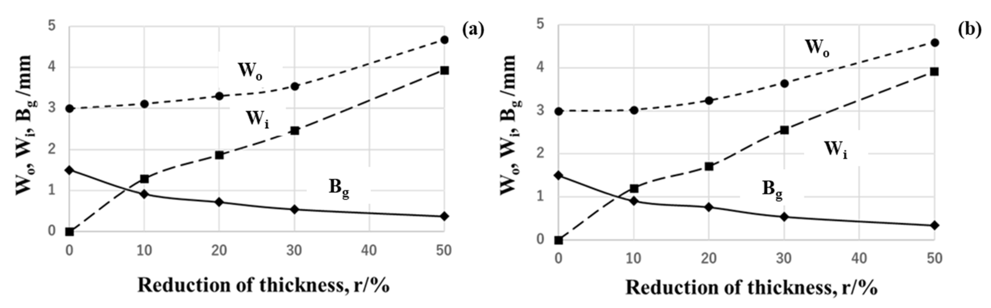
These Wo and Wc as well as the bulging displacement (Bg = (Wo − Wc)/2) were measured at each reduction in thickness and depicted in Figure 5 for the upset pure titanium wires by the Ns-SKD11 and Cs-SKD11 punches which both used the β-SiC-coated SiC die. No essential differences were seen in the variation of Wo, Wc, and Bg with increasing r between two punches in a similar manner to the upsetting of β-titanium wires in Figure 4. Wc monotonously approached Wo and Bg monotonically decreases with r. After [17], the monotonous decrease in Bg to nearly zero implies that the friction coefficient is very low at r = 50%.
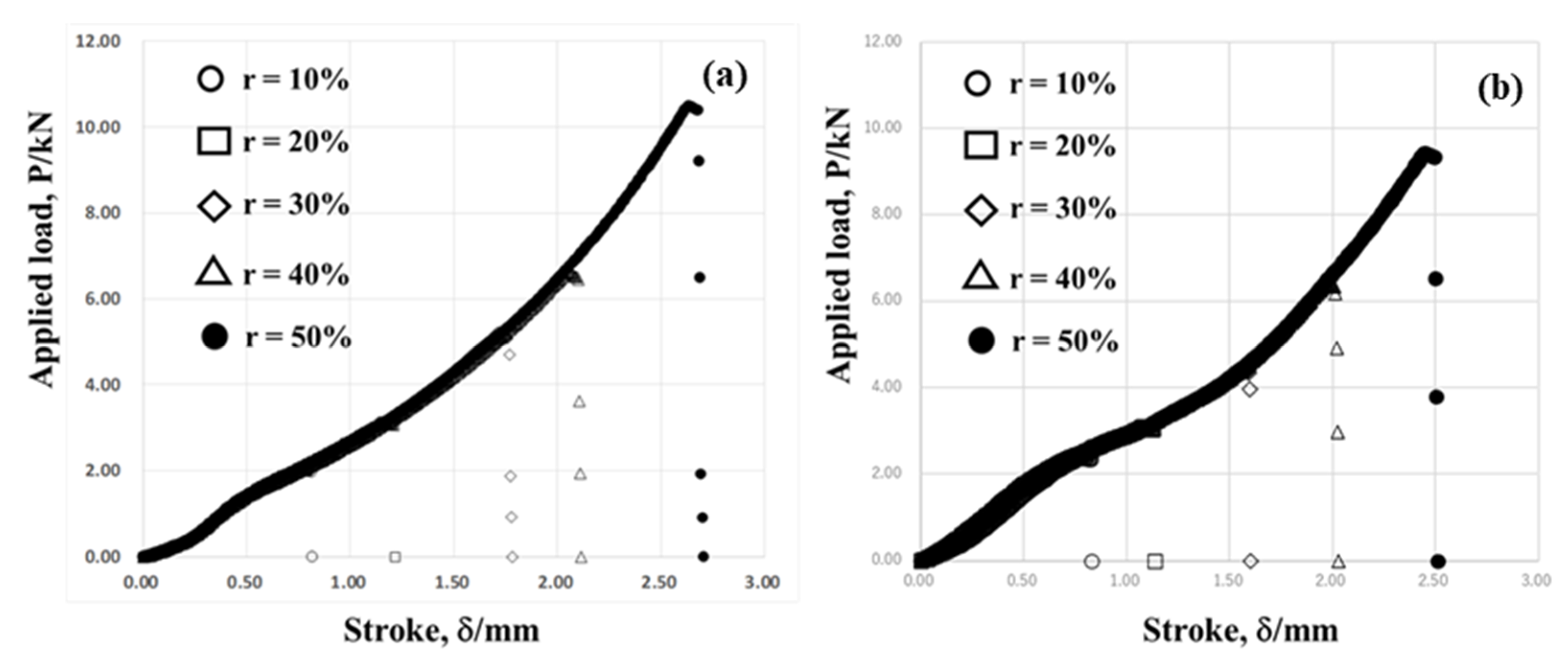
In the present CNC stamping, the stroke was measured by the linear-scale gage, and the applied load was also monitored by the load cell, which was embedded into the lower cassette die. Both the Cs-SKD11 punch and the β-SiC-coated SiC die were utilized for upsetting to describe the plastic flow behavior of pure titanium and β-titanium wires with increasing r. Figure 6a depicts each load–stroke relationship of forged pure titanium wires for upsetting down to r = 10%, 20%, 30%, 40%, and 50%, respectively. These five load–stroke relations were edited into a single master relationship between the applied load (P) to pure titanium wire and the stroke (δ) in upsetting. In this master curve, the applied load monotonously increases with the stroke since the pure titanium work flattens with r and its width broadens with the stroke, as observed in Figure 5b. As analyzed in Figure 6b, when forging the β-titanium wires with increasing r, both P and δ reduced more than those P and d at each r in Figure 6a. This reveals that β-titanium plastically deforms more homogeneously during upsetting, to provide the P and δ lower than those in the pure titanium. This comparison of P–δ relations between two works suggests that inner plastic straining behavior must be different between two works even when using the same punch and die pair.
3.2. Frictional Behavior on the Contact Interface
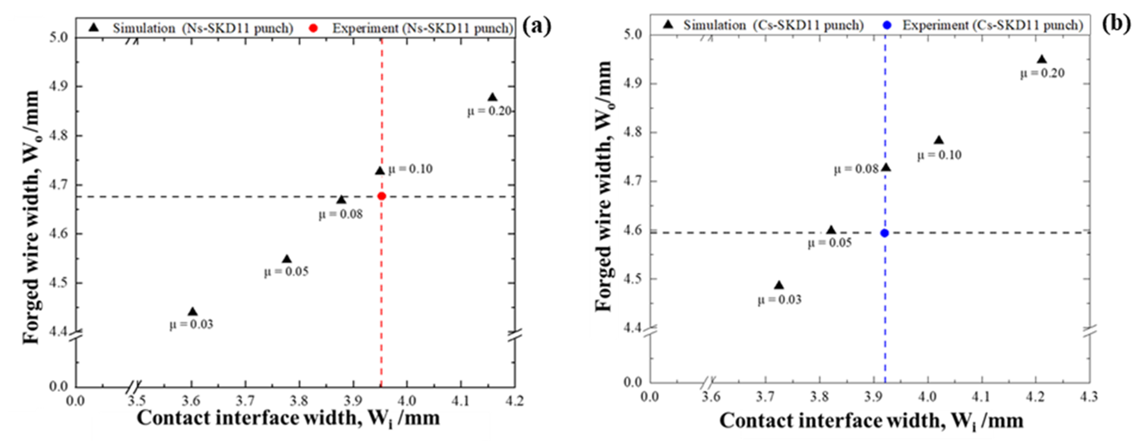
The regression curve by the finite element analysis was utilized to estimate the friction coefficient on the contact interface between the punch and die during forging when r = 50%. In the case of the Ns-SKD11 punch, both Wo and Wi increased with the friction coefficient (μ) in FEA. Since Wo = 4.68 mm and Wi = 3.95 mm at r = 50% during upsetting by using the Ns-SKD11 punch, the inverse analysis in Figure 7a estimates that 0.08 < μ0 < 0.10 on the interface between the Ns-SKD11 punch and the pure titanium works at r = 50%. As shown in Figure 7b, in case of the Cs-SKD11 punch, both Wo and Wi also increased with m in FEA. Since Wo = 3.92 mm and Wi = 4.59 mm at r = 50% in the upsetting, the inverse analysis in Figure 7b estimates that 0.05 < μ0 < 0.08 on the interface between the Cs-SKD11 punch and the pure titanium work at r = 50%. As seen in Figure 5, no essential difference was noticed in the macroscopic plastic flow behavior between two punches. This difference in μ0 is induced by the local plastic flow of pure titanium works on the contact interface to either punch.
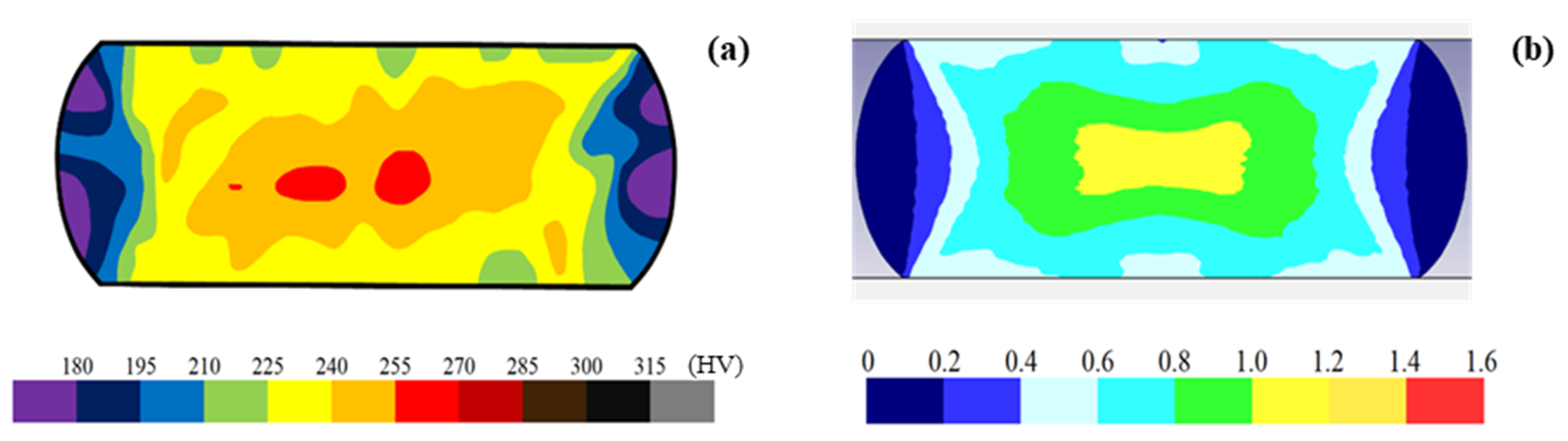
Let us evaluate the accuracy of the inverse analysis by FEM to describe the plastic flow of the titanium work. As shall be subsequently discussed, the inner work hardness increased during upsetting by the work hardening of titanium. Since the work hardening advanced with the increasing plastic strain, the measured hardness map must correspond to the calculated equivalent plastic strain distribution of the titanium work by FEA. Figure 8 compared the deformed wire-model shape and equivalent plastic strain distribution by FEM with the measured cross-sectional shape and hardness map of forged pure titanium wire at r = 50%. The simulated wire-model shape is in fairly good agreement with the measured cross-section of the wire at r = 50%. The calculated equivalent plastic strain distribution from the plastic strain components is nearly equal to the measured hardness mapping. This proves that the present FEA could afford to describe the wire deformation and strain distribution with sufficient accuracy to estimate the frictional condition on the contact interface.
3.3. Work-Hardening Behavior of Pure Titanium Work during the Forging Process
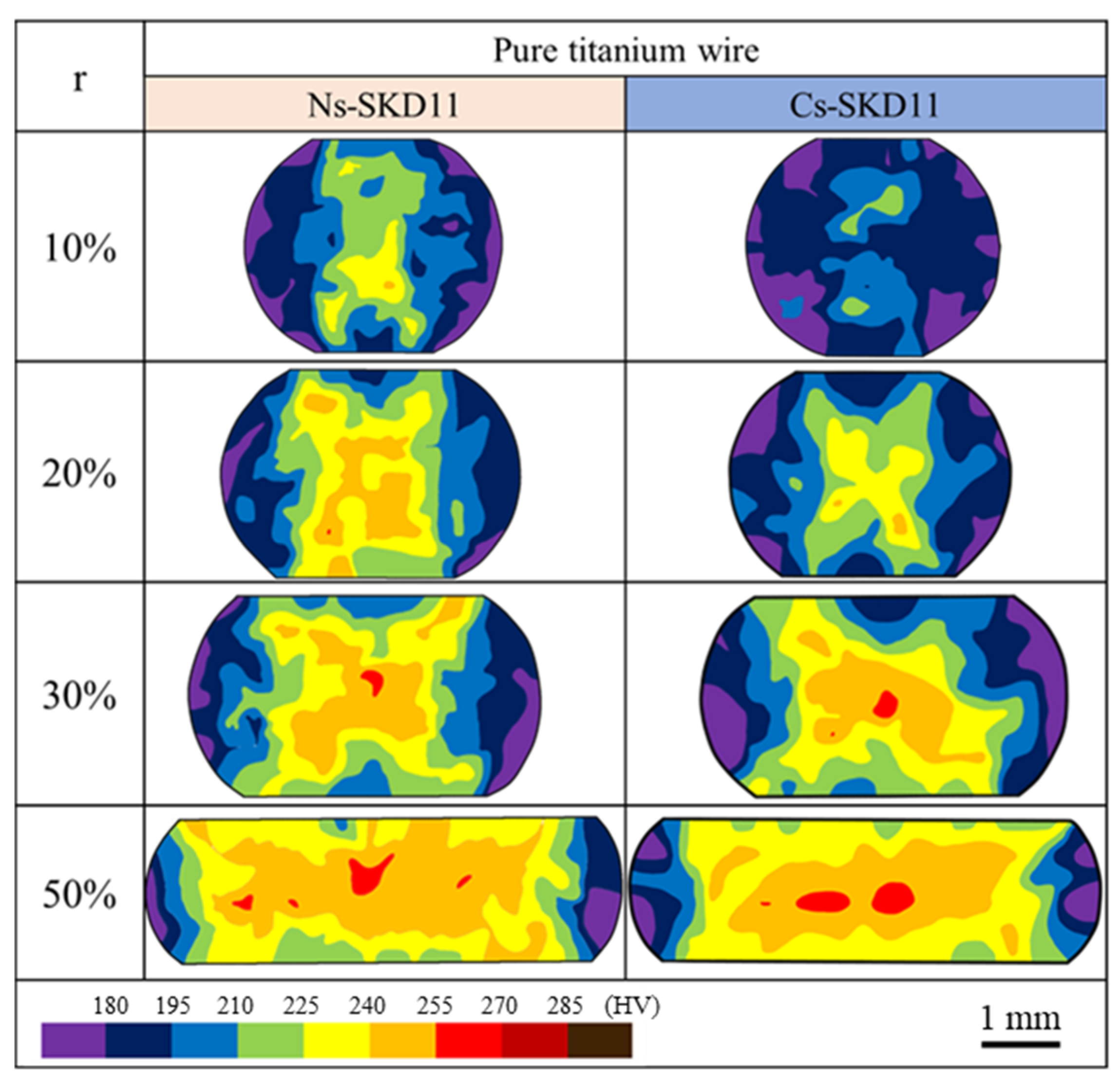
Figure 9 depicts the hardness maps of the forged pure-titanium specimens at each reduction in thickness by r = 10%, 20%, 30%, and 50 %, respectively, when using the Ns-SKD11 and Cs-SKD11 punches. When forged at r = 10 % by Ns-SKD11 punch, the yellow-colored zones with the hardness from 225 to 240 HV widely distributes at the central zone of the cross-section. In addition, a small orange-colored dot with a hardness >240 HV is also seen. This reveals that the work hardening starts at the center of the work even at r = 10% when using the Ns-SKD11 punch. On the other hand, when using the Cs-SKD11 punch, those high hardness zones are never detected at r = 10%. That is, the work-hardening process is retarded when using the Cs-SKD11 punch. At r = 10%, the maximum hardness is reduced by 35 HV when using the Cs-SKD11 punch. When forged at r = 20 % by Ns-SKD11 punch, the orange and red hardening zones with the hardness from 240 to 270 HV were seen at the center of the work. This hardened zone is never detected when using the Cs-SKD11 punch. The maximum hardness is reduced by 15 HV at r = 20% when using the Cs-SKD11 punch.
When forged at r = 30%, the hardness mapping in the cross-section of pure titanium work shows a significant difference between two punches. When using the Ns-punch, high hardness zones from 225 to 255 HV formed an X-lettered pattern at the center of work. As stated in [18], the highly strained zone forms a diagonally connected pattern in the cross-section of the forged specimen. That is, the shear-localization takes place to form a shear-band across the pure titanium work at r = 30% after [19]. This X-lettered pattern is a proof where the work hardening takes place with the shear localization when using the Ns-SKD11 punch. On the other hand, when using the Cs-SKD11 punch, no X-lettered pattern is formed at r = 30%. This proves that the shear localization does not occur in the work hardening. When forged at r = 50 % by using the Ns-SKD11 punch, the high hardness zones from 225 to 270 HV further broaden from the hardness map at r = 30% together with the shear localization. On the other hand, when using the Cs-SKD11 punch, those high hardness zones homogeneously broaden to nearly the whole cross-sectional area without shear localization.
The work-hardening process during the forging of two titanium works was analyzed by calculating the work-hardened zone area in the cross-section of the forged works. Two work-hardened zones were selected as a parameter; e.g., one zone with higher hardness than 225 HV and another zone with higher hardness than 240 HV. A225 is defined as a cross-sectional area for the former zone while A240 is a cross-sectional area for the latter zone. Against the total cross-sectional area Ar, the area ratio R225 is defined by A225/Ar, and the area ratio R240 is also defined by A240/Ar. They are calculated at each reduction in thickness to quantitatively describe the work-hardening behavior in the forging of pure titanium wires.
Figure 10 shows the variation of R225 and R240 with r when forging the pure titanium works. When using the Cs-SKD11 punch, R225 at r = 10% is null, and R225 at r = 20% is 0.13. While R225 at r = 10% is 0.08, R225 at r = 20% is 0.35 when using the Ns-SKD11 punch. This comparison reveals that the work-hardening zone area is suppressed by using the Cs-SKD11 punch even with less die-hardness than the Ns-SKD11 punch. R240 at r = 10% is null and R240 at r = 20% is 0.01 when using the Cs-SKD11 punch. R240 at r = 10% is 0.001, and R240 at r = 20% grows to 0.13 when using the Ns-SKD11 punch. Similarly to the difference in R225 between two punches, R240 proves that the Cs-SKD11 punch has a capacity to suppress the growth of work hardening. In fact, the yellow and orange-colored zones have nearly the same area in Figure 9. This indicates that the work-hardening process is retarded even at r = 10% when using Cs-SKD11 punch.
Let us investigate this suppression of work hardening at a high reduction in thickness during the forging of a pure titanium work. R225 at r = 30% is 0.38, and R225 at r = 50% is 0.73 when using the Cs-SKD11 punch; R225 at r = 30% is 0.39, and R225 at r = 50% is 0.72 when using the Ns-SKD11 punch. The low hardness zone area is nearly the same between two forging processes. R240 at r = 30% is 0.16, and R240 at r = 50% is 0.36 in the case of Cs-SKD11 punch; while R240 at r = 30% is 0.17, and R240 at r = 50% is 0.41 in the case of Ns-SKD11 punch. When using the Cs-SKD11 punch, R225 and R240 at r = 30% decreased slightly. When using the Cs-SKD11 punch, R225 and R240 at r = 30% have also approximately the same value as R225 and R240 at r = 20% by using Ns-SKD11. Furthermore, when using the Cs-SKD11 punch, the high hardness zones from 225 to 270 HV homogeneously broaden to nearly whole the cross-sectional area without shear localization, while those high hardness zones form a shear-localized pattern when using the Ns-SKD11 punch. This also shows that the work-hardening process is retarded by r = 10% when using the Cs-SKD11 punch. This proves that the Cs-SKD11 punch has the effect of suppressing work hardening due to the low friction conditions at r = 30% from at r = 20%.
3.4. Work-Hardening Behavior of β-Titanium Alloy Work during the Forging Process
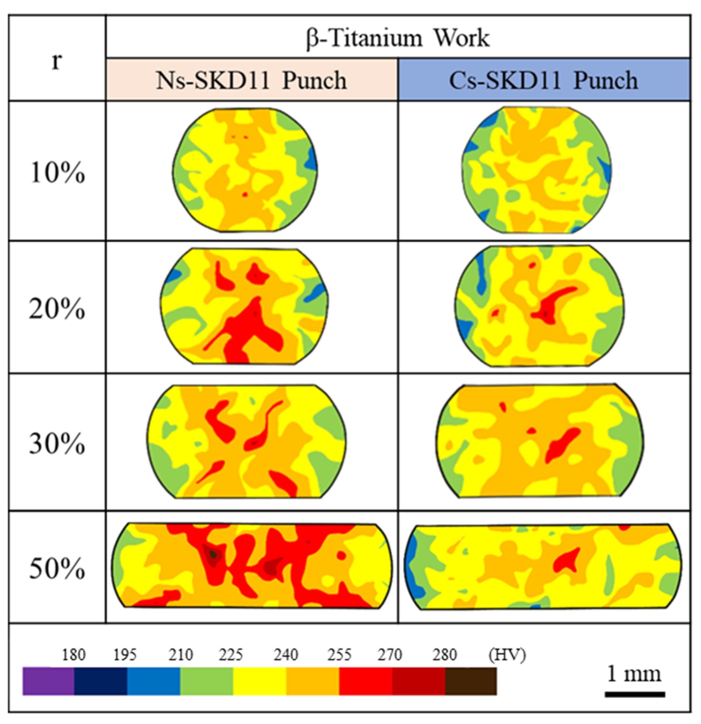
The β-titanium alloy wires were also upset by using the Ns-SKD11 and C-SKD11 punches with β-SiC-coated SiC die to describe the work-hardening behavior during forging. Figure 11 compares the hardness maps of the forged β-titanium alloy specimens at r = 10, 20, 30, and 50 % when using two punches. When forged at r = 10%, the hardness maps are significantly different to each other; high hardness zones from 240 to 255 HV form a shear-localized pattern and small, red-colored dots a hardness > 255 HV were also seen when using the Ns-SKD11 punch. This X-lettered pattern is a proof where the shear localization takes place with the work hardening of β-titanium work. In other words, no X-lettered pattern proves that the shear localization does not occur at r = 10% when using Cs-SKD11 punch.
When forged at r = 20 % by the Ns-SKD11 punch, the red- and orange-colored zones with the hardness from 240 to 270 HV are widely distributed at the center of the cross-section. This reveals that the work hardening significantly progresses at r = 20% when using Ns-SKD11 punch. When using the Cs-SKD11 punch, those high hardness zones are small and disperse; the work-hardening process is retarded when using the Cs-SKD11 punch. The maximum hardness is reduced by 15 HV when using the Cs-SKD11 punch. When forged at r = 30%, high hardness zones from 240 to 270 HV form a shear-localized pattern, especially red-colored-zones with a hardness from 255 to 270 HV distinctly form an X-lettered pattern. This X-lettered pattern proves that the work hardening takes place with the shear localization when using Ns-SKD11 punch. In other words, no X-lettered pattern is seen when using the Cs-SKD11 punch; the shear localization does not occur in the work hardening.
When forged at r = 50 % by using the Ns-SKD11 punch, the high hardness zones from 255 to 300 HV further broaden from the hardness map at r = 30% together with the shear localization. When using the Cs-SKD11 punch, those high hardness zones are doted in local; the β-titanium work homogeneously flattens without hardening. In fact, the maximum hardness at r = 50% is 300 HV when using the Ns-SKD11 punch, while it is 270 HV when using the Cs-SKD11 punch. This homogeneous hardening with a low maximum hardness in local proves that the β-titanium work is uniformly forged by using the Cs-SKD11 punch without severe work hardening.
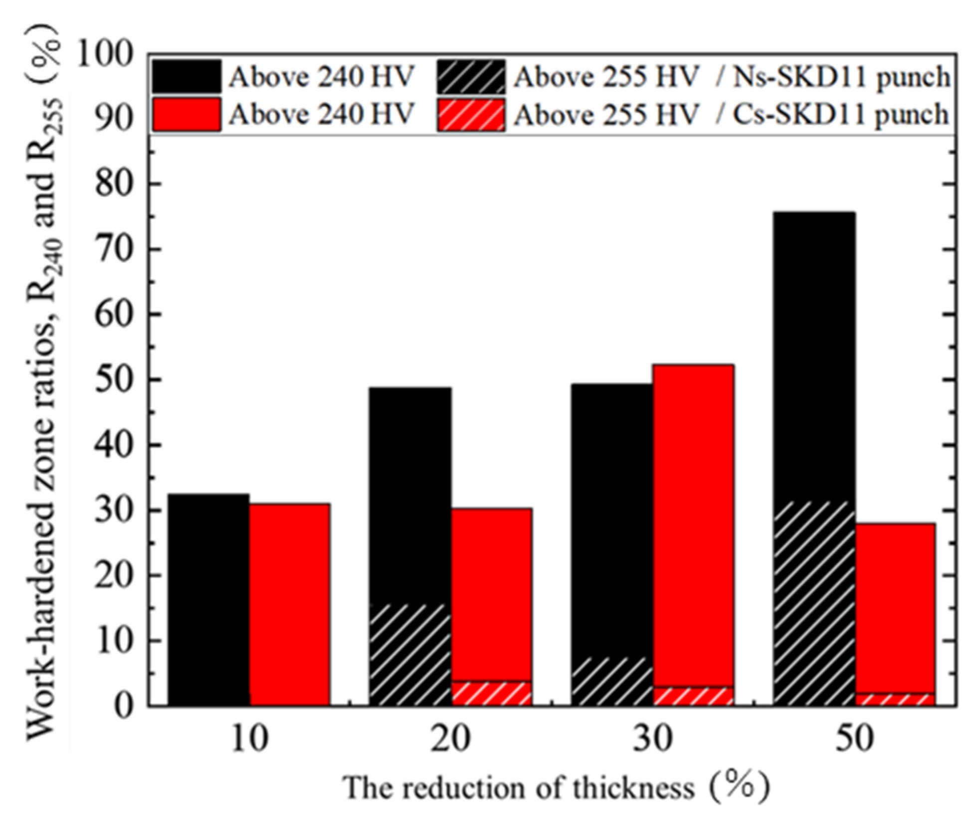
Figure 12 shows the variation of R240 and R255 with r in forging the β-titanium works. When using the Cs-SKD11 punch, R240 at r = 10% is 0.31 and R240 at r = 20% is 0.30. While R240 at r = 10% is 0.33 and R240 at r = 20% is 0.49 when using the Ns-SKD11 punch. When using the Cs-SKD11 punch, R255 at r = 10% is null and R255 at r = 20% is 0.04, while R255 at r = 10% is 0.02 and R255 at r = 20% is 0.16 when using the Ns-SKD11 punch. This extension of R255 with r when using the Ns-SKD11 punch is attributed to shear localization at r = 10% and 20% and work hardening at r = 20%. On the other hand, when using the Cs-SKD11 punch, a little significant increase in R240 and R255 is noticed as r = 10% and 20%. This proves that work hardening is suppressed by using the Cs-SKD11 punch.
When using the Cs-SKD11 punch, R240 at r = 30% is 0.52 and R240 at r = 50% is 0.28. While R240 at r = 30% is 0.49, R240 at r = 50% grows to 0.76 when using the Ns-SKD11 punch. When using the Cs-SKD11 punch, R255 at r = 30% is 0.03 and R255 at r = 50% is 0.02. While R255 at r = 30% is 0.08, R255 at r = 50% grows to 0.31 when using the Ns-SKD11 punch. The high hardness zones from 255 to 300 HV at r = 50% further broaden from the hardness map at r = 30% together with the shear localization. On the other hand, when using the Cs-SKD11 punch, R255 at r = 30% is almost the same as R255 at r = 20% but R240 at r = 30% is increased by 0.22 at r = 50%. Although the high hardness zones from 240 to 270 HV broaden without shear localization. This shows that the work-hardening process is retarded when using the Cs-SKD11 punch. The forging process even at r = 50% is characterized by slightly work hardening without shear localization. Less work hardening leads to a significant suppression of the shear localization.
3.5. Contact Interface Analysis by SEM-EDX and Raman Spectroscopy
The difference of frictional and work-hardening behavior between Ns- and Cs-SKD11 punches is attributed to the contact interface conditions between the punch and the titanium work during forging. SEM-EDX analysis was performed to describe the adhesion of debris particles from the work to contact interface.
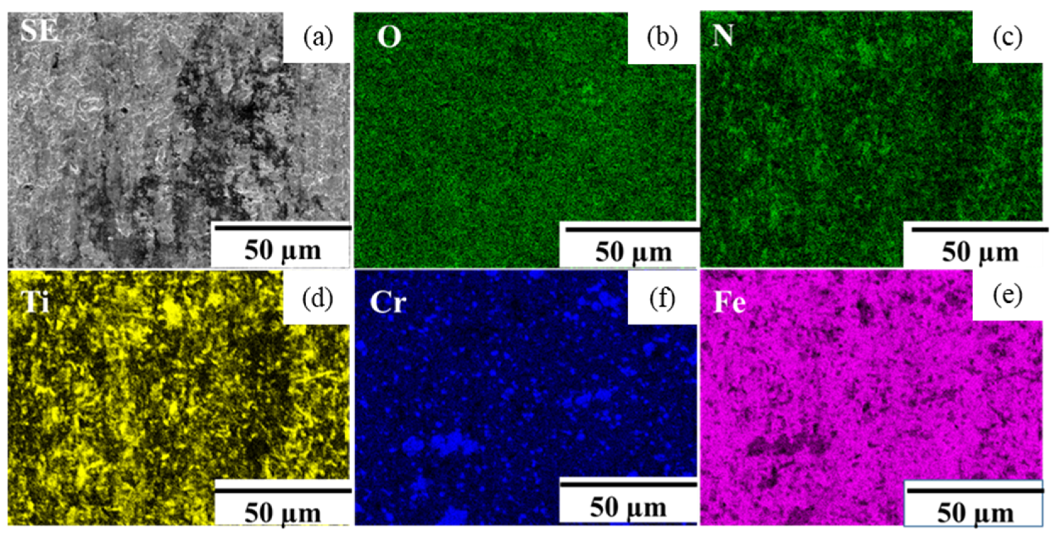
Figure 13 depicts the SEM image and element mapping at the center of the contact interface between the pure titanium work and the Ns-SKD11 punch after continuously forging twenty times down to 50% in the reduction in thickness. Although the interface has a sufficient content of nitrogen solute on the interface, the severe adhesion of titanium debris was seen on the interface. In the previous studies on the forging and deep-drawing of pure titanium works in [11,16,20], the severe adhesion of the titanium fresh surface to punches and dies induced high friction and chemical galling. In contrast to the adhesion of metallic titanium on the contact interface, the nitrogen and titanium mapping are in agreement with each other on the interface in Figure 13. On the other hand, the oxygen mapping has no correlations with both mappings. The iron mapping represents the matrix of SKD11; the chromium mapping denotes precipitates embedded in the matrix for chromium carbide. Hence, this high correlation between nitrogen and titanium mapping on the contact interface reveals that a thin titanium debris film Ti (N) with nitrogen solutes or the titanium nitride film TiNx (x = 1 or 2) is formed on the interface. Relatively low frictional behavior with 0.08 < μ0 < 0.10 in Figure 7a reveals that adhesive wear on the contact interface is more reduced by Ti (N) or TiNx film formation than by the adhesion of metallic titanium debris in [11,16]. The intensive work-hardening behavior in Figure 9 and Figure 11 also reveals that severe work hardening and shear localization cannot be suppressed by this film formation on the contact interface.
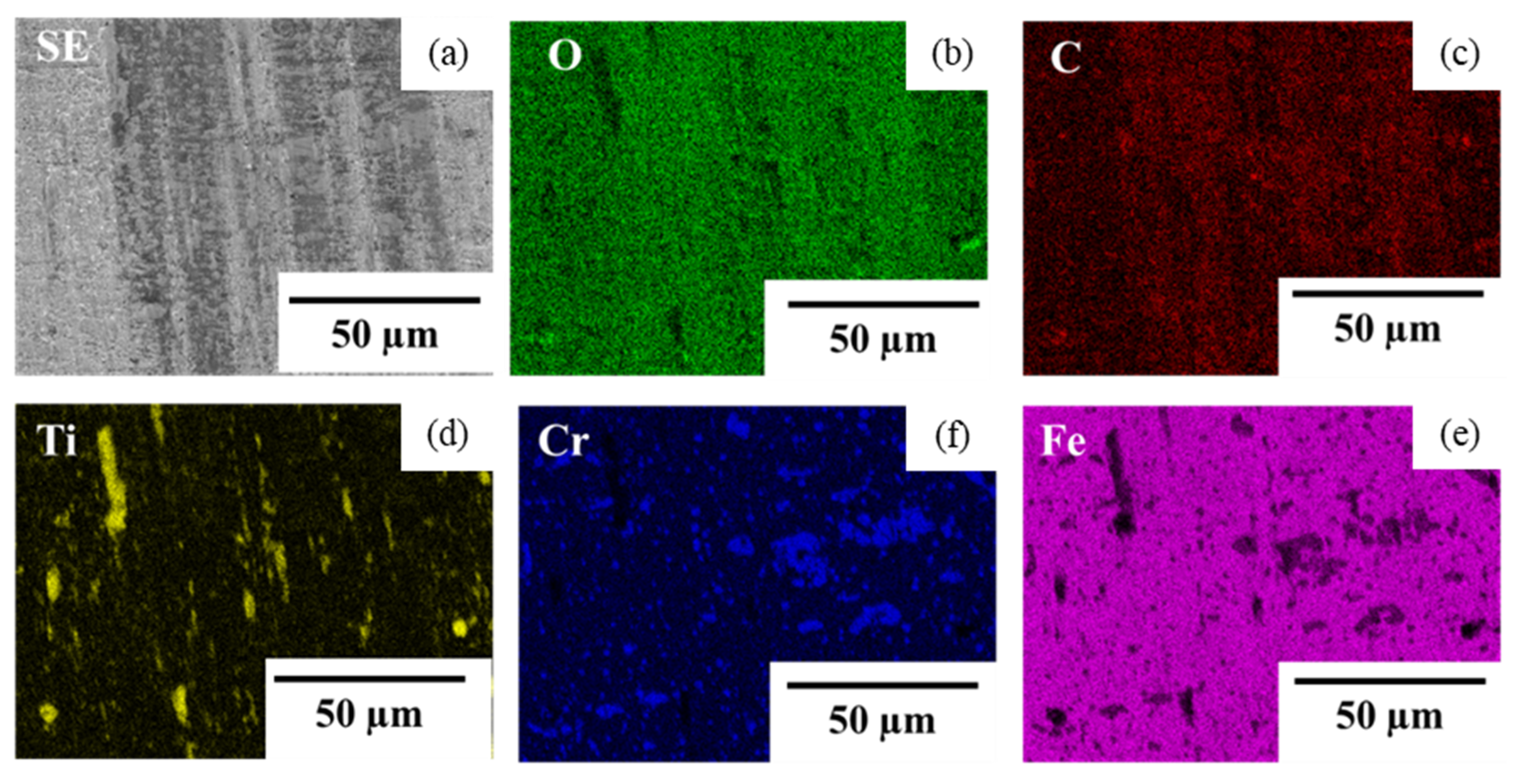
Figure 14 depicted the SEM image and element mapping at the center of the contact interface between the pure titanium work and the Cs-SKD11 punch after continuously forging twenty times down to a 50% in reduction in thickness. The iron and chromium maps were the same as those in Figure 13. The oxygen is distributed uniformly on the interface except for the zones with titanium; the titanium map is exclusively detected on the interface in the oxygen map. This implies that titanium oxides were synthesized on the interface in a completely different way to how they were in the previous results in [7,20] where the titanium oxides deposited on the die surfaces as debris particles. The carbon is homogeneously distributed on the contact interface in the same stripe-pattern as seen in the SEM image. If these carbons were detected from iron or chromium carbides in SKD11 matrix, this carbon map could have a correlation with the iron or chromium maps. No correlations between the carbon and iron/chromium maps in Figure 14 reveals that the detected carbon on the interface does not come from carbides but from the isolated carbon from the Cs-SKD11 punch matrix.
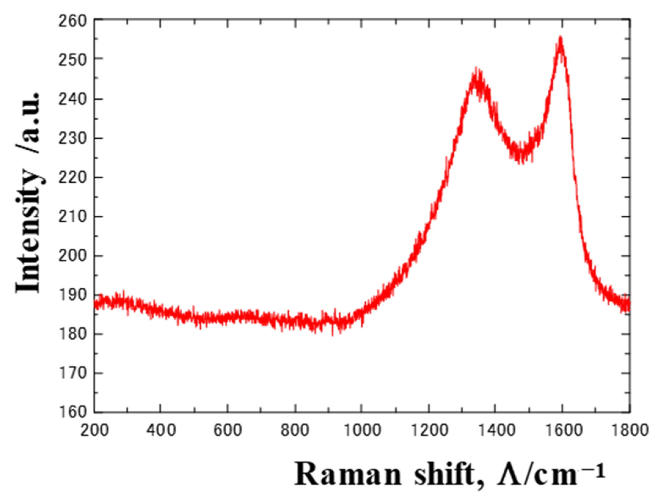
Let us demonstrate that the carbon map in Figure 14 is attributed to the isolated carbon using the Raman spectroscopy. This Raman spectroscopy is sensitive to the bound and unbound carbons; e.g., the unbound carbon is characterized by the graphitic peak at 1600 cm−1 and the disorder peak at 1350 cm−1. Figure 15 depicts the Raman spectra at the center of the contact interface. No peaks other than these G- and D-peaks were detected in the Raman shift range from 200 cm−1 to 1800 cm−1. No free carbons separated from the carbides in SKD11 at RT [21]. This Raman spectrum proves that the carbon map in Figure 14 is attributed to the unbound carbon, isolated from the Cs-SKD11 matrix.
4. Discussion
In the normal metal forming, the bare WC (Co) and tool steel dies suffered from severe galling to the fresh surface of titanium works [7]. Most of the coated dies risked being damaged by chemical galling to the titanium works even under liquid lubrication [8,22]. Two surface modifications by the nitrogen- and carbon-supersaturation were utilized to investigate the effect of nitrogen and carbon solutes on the anti-galling behavior. As reported in [9,10,23,24], the Ns-SKD11 punch by plasma nitriding at 673 K for 14.4 ks has three features superior to bare WC (Co) and ceramic coatings: Its higher average hardness exceeds 1400 HV. Its nitrided layer with a thickness more than 50 μm was available as a hardened layer; Its higher nitrogen solute content with more than 4 mass% enhanced the chemical stability by the attraction of constituent iron atoms to nitrogen solutes. This superiority reflects on the relatively low friction on the contact interface between Ns-SKD11 punch and titanium works. SEM-EDX analysis on the contact interface of the Ns-SKD11 punch after continuously upsetting in 20 shots up to r = 50%, revealed that the Ti (N) or TiNx layer was formed by the affinity of nitrogen to titanium fresh debris fragments on the interface. In this in situ synthesis of Ti (N) or TiNx on the interface, the nitrogen solutes were pushed up to the contact interface to react with the fresh titanium debris particles. This chemical galling process induces severe work hardening with shear localization during the forging steps even when using the Ns-SKD11 punch.
This Ns-SKD11 punch was exchanged with the Cs-SKD11 in the same upsetting experiments. The friction coefficient on the contact interface was reduced to be less than 0.1. The onset of work hardening was retarded to a higher reduction in thickness. No shear localization was observed in every reduction in thickness during the upsetting experiments. This improvement in titanium workability comes from the chemical role of isolated carbon from the Cs-SKD11 punch matrix. No correlation between the carbon and titanium element maps in Figure 14 proved that no titanium carbides were synthesized on the contact interface. The exclusive mapping of oxygen and titanium proved that no titanium oxides were formed on the contact interface. The homogeneously distributing carbon map with small traces of metallic titanium on the interface demonstrated that the contact interface was prevented from the adhesion of metallic titanium.
In the conventional solid lubrication on the contact interface between the punch and work, the solid lubricants were painted on the surface before forging, and, if needed, they were repeatedly supplied to the interface during forging to preserve the lubricating film on it. When using the Cs-SKD11 punch, the free carbon film was formed as a friction film on the contact interface. This film was composed of the isolated carbons from the Cs-SKD11 punch matrix during the forging process. In a similar manner to the surface diffusion of nitrogen solutes from the Ns-SKD11 matrix in the in situ synthesis of Ti (N) or TiNx, the supersaturating carbon solutes in the Cs-SKD11 matrix diffuse to the contact interface by the stress gradient during forging, agglomerate by themselves without the formation of the titanium carbides, and form a carbon-derivative friction film on the contact interface. Theoretical study just started to explain this carbon isolation and diffusion processes in an iron matrix at low temperature [25]. Through jumping between the octahedral vacancy sites, the carbon solutes could diffuse to the highly stressed contact interface and form the friction film for in situ solid lubrication.
This in situ solid lubrication has several superiorities to conventional solid lubrication. It needs no external supply of lubricants since the carbon friction film is preserved during the continuous forging steps. It is free from the adhesion of titanium oxide debris particles to punch and die surfaces since no titanium oxides are synthesized on the carbon-accommodated interface. The original SKD11 punch surface condition is preserved through the whole forging steps. If needed, it is recovered by polishing the carbon-accommodated interface; the in situ solid lubrication works again in the successive forging steps.
The low frictional state is sustained through all the forging steps even with a high reduction in thickness and it is free from the plastic localization. After [18,19,26,27,28], the high frictional state by chemical galling triggers the deformation mode change in the upsetting step from the uniaxial compression to the shear localization. In the normal upsetting process, the work at the vicinity of the contact interface to dies seizes like a dead metal to induce the plastic localization and result in the final failure of work. In the case when the work homogeneously flows along the contact interface, the uniaxial compression deformation advances with flattening even under a high reduction in thickness.
The pure titanium and β-titanium alloy were employed as a work material. As compared through Figure 9, Figure 10 and Figure 11, the β-titanium wires were homogeneously forged with a great retardation of the work hardening even by using the same Cs-SKD11 punch. This improvement of plastic flow behavior comes from the allowable slipping planes of β-titanium. As stated in [29], the crystallographic structure of titanium was β-phase stabilized to have a bcc-structure and to be readily cold-formed compared to the original hcp-structured titanium. This readily cold-forming capacity of β-titanium is also preserved in the cold forging with a high reduction in thickness. To be noticed, the homogeneous plastic flow with less work hardening is preserved during every forging step by using the CS-SKD11 punch.
5. Conclusions
The cold forging of titanium and titanium alloy with a high reduction in thickness was performed by using the nitrogen- and carbon-supersaturated SKD11 punches together with the β-SiC-coated SiC die. The upsetting behavior of up to 50% in the reduction in thickness was described by measuring the work cross-sectional shape and monitoring the load–stroke relationship. The friction coefficient on the contact interface was estimated by the inverse analysis with the use of a three-dimensional finite element model. The hardness mapping of the forged work at every reduction in thickness was performed to describe the work-hardening behavior in the work. These tooling systems reduced the friction coefficient on the contact interface between the punch and die. When using the nitrogen-supersaturated SKD11 (Ns-SKD11) punch, the upsetting process accompanied with severe work hardening with shear localization. This work hardening was retarded in upsetting and no shear localization occurred when using the carbon supersaturated SKD11 (Cs-SKD11) punch.
After the SEM-EDX analysis on the contact interface, a thin Ti (N) or TiNx film was formed at the center of the interface when using the Ns-SKD11 punch. The plastic straining in the forged work materials was enhanced through this partial chemical adhesion to stimulate the work hardening and shear localization. When using the Cs-SKD11 punch, no titanium oxides and carbides were synthesized on the interface. A uniform carbon map was in situ formed as a friction film on the contact interface to reduce the friction coefficient and to retard the work-hardening process. Under this in situ solid lubrication, the forging process up to a higher reduction in thickness can be repeatedly performed at low friction and work hardening without any chemical galling. Due to the retardation of the work hardening, the heat annealing process can be saved for the near-net forging of titanium works to products. In particular, the plastic flow of β-titanium works becomes significantly homogeneous and sufficiently free from shear localization to make complex shaping. Its readily cold-forging capability is made in full use for the industrial production of parts and products. A high qualification of titanium and titanium alloy products and galling-free tooling is fulfilled in this green forging.
Author Contributions
Conceptualization, T.A. and T.S.; methodology, T.A. and T.S.; validation, T.F. and S.I.; investigation, S.I. and T.F.; writing—original draft preparation, T.A. and T.S.; writing—review and editing, T.F. and T.S.; supervision, T.A.; project administration, T.S. All authors have read and agreed to the published version of the manuscript.
Funding
This research received no external funding.
Data Availability Statement
Not applicable.
Acknowledgments
The authors would like to express their gratitude to S. Kurozumi (Nano-Film Coat, llc.), Tomoaki Yoshino (Komatsu-Seiki Kosakusho, Co., Ltd.) and T. Kihara (Cherman, Co., Ltd.) for their help in experiments.
Conflicts of Interest
The authors declare no conflict of interest.
References
- Shirvani, B.; Clarke, R.; Duflou, J.; Merklein, M.; Micari, F.; Griffiths, J. Stamping of titanium sheets. Key Eng. Mater. 2009, 410–411, 279–288. [Google Scholar]
- Clauss, M.; Graf, S.; Gersbach, S.; Hintermann, B.; Ilchmann, T.; Knupp, M. Material and biofilm load of K wires in toe surgery: Titanium versus stainless steel. Clin. Orthop. Relat. Res. 2013, 471, 2312–2317. [Google Scholar] [CrossRef] [Green Version]
- Moxson, V.S.; Froes, F.H. Fabricating sports equipment components via powder metallurgy. JOM 2003, 53, 39–41. [Google Scholar] [CrossRef]
- Höher, J.; Livesay, G.A.; Ma, C.B.; Withrow, J.D.; Fu, F.H.; Woo, S. Hamstring graft motion in the femoral bone tunnel when using titanium button/ polyester tape fixation. Knee Surg. Sports Traumatol. Arthrosc. 1999, 7, 215–219. [Google Scholar] [CrossRef]
- Pornsin-Sirirak, T.N.; Tai, Y.C.; Nassef, H.; Ho, C.M. Titanium-alloy MEMS wing technology for a micro aerial vehicle application. Sens. Actuators A Phys. 2001, 89, 95–103. [Google Scholar] [CrossRef]
- Aimi, M.F.; Rao, M.P.; MacDonald, N.C.; Zuruzi, A.S.; Bothman, D.P. High-aspect-ratio bulk micromachining of titanium. Nat. Mater. 2004, 3, 103–105. [Google Scholar] [CrossRef]
- Kihara, T. Visualization of deforming process of titanium and titanium alloy using high speed camera. In Proceedings of the 2019 JSTP Conference, Kyoto, Japan, 7–9 June 2019; pp. 41–42. [Google Scholar]
- Dohda, K.; Aizawa, T. Tribo-characterization of silicon doped and nano-structured DLC coatings by metal forming simulators. Manuf. Lett. 2014, 2, 82–85. [Google Scholar] [CrossRef]
- Aizawa, T. Low temperature plasma nitriding of austenitic stainless steels. In Stainless Steels and Alloys; IntechOpen: London, UK, 2019; Chapter 3; Volume 3, pp. 31–50. [Google Scholar]
- Farghali, A.; Aizawa, T. Nitrogen supersaturation process in the AISI420 martensitic stainless steels by low temperature plasma nitriding. ISIJ Int. 2018, 58, 401–407. [Google Scholar] [CrossRef] [Green Version]
- Aizawa, T.; Yoshino, T.; Suzuki, Y.; Shiratori, T. Anti-galling cold, dry forging of pure titanium by plasma-carburized AISI420J2 dies. Appl. Sci. 2021, 11, 595. [Google Scholar] [CrossRef]
- Aizawa, T.; Yoshino, T.; Suzuki, Y.; Shiratori, T. Free-forging of pure titanium with high reduction of thickness by plasma-carburized SKD11 dies. Materials 2021, 14, 2536. [Google Scholar] [CrossRef]
- Aizawa, T.; Yoshino, T.; Shiratori, T. Galling-free cold forging of titanium alloys by the plasma carburized SKD11 dies. In Proceedings of the 13th AWMFT-ASPS Conference, Shanghai, China, 3–6 November 2021. (In press). [Google Scholar]
- Ishiguro, S.; Aizawa, T.; Shiratori, T. Characterization on forged titanium and titanium alloys by carbon supersaturated SKD11 punch. In Proceedings of the 13th AWMFT-ASPS Conference, Shanghai, China, 3–6 November 2021. (In press). [Google Scholar]
- Aizawa, T.; Rsadi, I.; Yunata, E.E. High density RF-DC plasma nitriding under optimized conditions by plasma diagnosis. Appl. Sci. 2022, 12, 3706. [Google Scholar] [CrossRef]
- Aizawa, T.; Yoshino, T.; Shiratori, T.; Dohda, K. Anti-galling β-SiC coating dies for fine cold forging of titanium. J. Phys. Conf. Ser. 2021, 1777, 012043. [Google Scholar] [CrossRef]
- Hsu, Y.; Lin, Y.K.; Sun, K.W.; Wu, S.H. Development of a continuous rolling process for titanium wires. China Steel Technol. Res. 2012, 25, 28–35. [Google Scholar]
- Chen, Y.J.; Meyers, M.A.; Nesterenko, V.F. Spontaneous and forced shear localization in high-strain-rate deformation of tantalum. Mater. Sci. Eng. 1999, 268, 70–82. [Google Scholar] [CrossRef]
- Solomonov, K.N.; Tishchuk, L.I.; Lezhnev, S.N.; Listrov, E.A. Simulation of upsetting process using kinematic schemes of metal flow. IOP Conf. Ser. Mater. Sci. Eng. 2020, 971, 022041. [Google Scholar] [CrossRef]
- Kataoka, S.; Murakawa, M.; Aizawa, T.; Ike, H. Tribology of dry deep-drawing of various metal sheets wit use of ceramic tools. Surf. Coat. Technol. 2004, 178, 582–590. [Google Scholar] [CrossRef]
- Urbonaite, S.; Hälldahl, L.; Svensson, G. Raman spectroscopy studies of carbide derived carbons. Carbon 2008, 46, 1942–1947. [Google Scholar] [CrossRef]
- Condat, Forging—Lubricants—Coatings. Available online: https://www.condat-lubricants.com/product/forging-lubricants-coatings/ (accessed on 12 June 2022).
- Borgioli, F.; Galvanetto, E.; Bacci, T. Corrosion behavior of low temperature nitrided nickel-free, AISI200 and AISI300 series austenitic stainless steels in NaCl. Corros. Sci. 2018, 136, 352–365. [Google Scholar] [CrossRef]
- Domain, C.; Becquart, C.S.; Foct, J. Ab initio study of foreign interstitial atom (C, N) interactions with intrinsic point defects in α-Fe. Phys. Rev. B 2004, 69, 144122. [Google Scholar] [CrossRef]
- Buggenhoudt, O.; Schuler, T.; Fu, C.C.; Bechade, J.L. Predicting carbon diffusion in cementite from first principles. Phys. Rev. Mater. 2021, 5, 063401. [Google Scholar] [CrossRef]
- Li, H.; Fu, M.W.; Lu, J.; Yang, H. Ductile fracture: Experiments and computations. Int. J. Plast. 2011, 27, 147–180. [Google Scholar] [CrossRef]
- Tarasov, S.Y. Localization of strain in friction. Met. Sci. Heat Treat. 2006, 48, 226–230. [Google Scholar] [CrossRef]
- Nielsen, K.L.; Pardoen, T.; Tvergaard, V.; de Meester, B.; Simar, A. Modeling of plastic flow localization and damage development in friction stir welded 6005A aluminum alloy using physics based strain hardening law. Int. J. Solids Struct. 2010, 47, 2359–2370. [Google Scholar] [CrossRef] [Green Version]
- Martin, J. Materials for Engineering; Woodhead Publishing: Sawston, Cambridge, UK, 2006. [Google Scholar]
Figure 1.
CNC-forging system for upsetting of the titanium and titanium alloy wires: (a) press machine; and (b) schematic view of forging die.
Figure 1.
CNC-forging system for upsetting of the titanium and titanium alloy wires: (a) press machine; and (b) schematic view of forging die.

Figure 2.
The inverse analysis of the friction coefficient on the contact interface with the aid of the finite element analysis.
Figure 2.
The inverse analysis of the friction coefficient on the contact interface with the aid of the finite element analysis.

Figure 3.
Generation of hardness mapping on the cross-section of forged works.

Figure 4.
Upsetting forging behavior of β-titanium alloy wires with an increasing reduction in thickness with the use of Cs-SKD11 punch and β-SiC-coated SiC die. (a) r = 10%, (b) r = 20%, (c) r = 30%, (d) r = 40%, (e) r = 50%, (f) r = 58%.
Figure 4.
Upsetting forging behavior of β-titanium alloy wires with an increasing reduction in thickness with the use of Cs-SKD11 punch and β-SiC-coated SiC die. (a) r = 10%, (b) r = 20%, (c) r = 30%, (d) r = 40%, (e) r = 50%, (f) r = 58%.

Figure 5.
Variation of the wire width (Wo), the contact interface width (Wi) and the bulging displacement (Bg) with the increasing reduction in thickness. (a) Forged pure titanium wire by using the Ns-SKD11 punch, and (b) forged pure titanium wire by using the Cs-SKD11 punch.
Figure 5.
Variation of the wire width (Wo), the contact interface width (Wi) and the bulging displacement (Bg) with the increasing reduction in thickness. (a) Forged pure titanium wire by using the Ns-SKD11 punch, and (b) forged pure titanium wire by using the Cs-SKD11 punch.

Figure 6.
The load–stroke (P-δ) relationship in upsetting the pure titanium and β-titanium wires down to the specified reduction in thickness (r) by using the Cs-SKD11 punch and the β-SiC-coated SiC die. (a) The P-δ relationship for upsetting the pure titanium wire, and (b) the P-δ relationship for upsetting the β-titanium wire.

Figure 7.
Determination of the friction coefficient (μ0) on the contact interface between the punch and the pure titanium wire with the aid of the finite element analysis. (a) Estimate of μ0 on the contact interface between Ns-SKD11 punch and pure titanium wire, and (b) estimate of μ0 on the contact interface between Cs-SKD11 punch and pure titanium wire.

Figure 8.
Comparison of the cross-sectional shape and hardness mapping of forged pure titanium at r = 50 % with the simulated shape and equivalent strain distribution by finite element analysis. (a) Experimentally measured cross-section of titanium wire at r = 50% with hardness map, and (b) deformed finite element model and calculated equivalent strain distribution by FEA.

Figure 9.
Comparison of the work-hardening behavior during the forging process of pure titanium wires between the Ns-SKD11 and Cs-SKD11 punches.
Figure 9.
Comparison of the work-hardening behavior during the forging process of pure titanium wires between the Ns-SKD11 and Cs-SKD11 punches.

Figure 10.
Variation of the work-hardening area in the forged pure titanium wire with the increasing reduction in thickness.
Figure 10.
Variation of the work-hardening area in the forged pure titanium wire with the increasing reduction in thickness.

Figure 11.
Variation of the work-hardening behavior during the forging process of the β-titanium alloy wires between the Ns-SKD11 and Cs-SKD11 punches.
Figure 11.
Variation of the work-hardening behavior during the forging process of the β-titanium alloy wires between the Ns-SKD11 and Cs-SKD11 punches.

Figure 12.
Variation of the work-hardening area in the forged β-titanium alloy wire with an increasing reduction in thickness.
Figure 12.
Variation of the work-hardening area in the forged β-titanium alloy wire with an increasing reduction in thickness.

Figure 13.
SEM image and element mapping at the center of the contact interface between the pure titanium and the Ns-SKD11 punch after continuously forging 20 times with r = 50%. (a) SE image, (b) Oxide (O), (c) Nitride (N), (d) Titanium (Ti), (e) Chromium (Cr), (f) Iron (Fe).
Figure 13.
SEM image and element mapping at the center of the contact interface between the pure titanium and the Ns-SKD11 punch after continuously forging 20 times with r = 50%. (a) SE image, (b) Oxide (O), (c) Nitride (N), (d) Titanium (Ti), (e) Chromium (Cr), (f) Iron (Fe).

Figure 14.
SEM image and element mapping at the center of the contact interface between the pure titanium and the Cs-SKD11 punch, after continuously forging 20 times with r = 50%. (a) SE image, (b) Oxide (O), (c) Nitride (N), (d) Titanium (Ti), (e) Chromium (Cr), (f) Iron (Fe).
Figure 14.
SEM image and element mapping at the center of the contact interface between the pure titanium and the Cs-SKD11 punch, after continuously forging 20 times with r = 50%. (a) SE image, (b) Oxide (O), (c) Nitride (N), (d) Titanium (Ti), (e) Chromium (Cr), (f) Iron (Fe).

Figure 15.
Raman spectrum at the center of contact interface between the Cs-SKD11 punch and the pure titanium work after continuously forging 20 times down to 50% in the reduction in thickness.
Figure 15.
Raman spectrum at the center of contact interface between the Cs-SKD11 punch and the pure titanium work after continuously forging 20 times down to 50% in the reduction in thickness.


Table 1.
Plasma nitriding and carburizing process conditions.
| Process | Pre Sputtering | Nitriding | Carburizing |
|---|---|---|---|
| Using Gas/Gas flow (mL/min) | Argon/100 | Nitrogen and hydrogen gas mixture/160 Hydrogen/30 | Argon/100 Hydrogen/80 Methane (CH4)/20 |
| Processing time (s) | 1800 | 14,400 | 14,400 |
| Temperature (K) | 673 | 673 | 673 |
| Pressure | 70 | 70 | 70 |
| RF-voltage | 200 | 200 | 200 |
| DC−bias | −600 | −600 | −600 |
Publisher’s Note: MDPI stays neutral with regard to jurisdictional claims in published maps and institutional affiliations. |
© 2022 by the authors. Licensee MDPI, Basel, Switzerland. This article is an open access article distributed under the terms and conditions of the Creative Commons Attribution (CC BY) license (https://creativecommons.org/licenses/by/4.0/).
Share and Cite
MDPI and ACS Style
Ishiguro, S.; Aizawa, T.; Funazuka, T.; Shiratori, T. Green Forging of Titanium and Titanium Alloys by Using the Carbon Supersaturated SKD11 Dies. Appl. Mech. 2022, 3, 724-739. https://0-doi-org.brum.beds.ac.uk/10.3390/applmech3030043
AMA Style
Ishiguro S, Aizawa T, Funazuka T, Shiratori T. Green Forging of Titanium and Titanium Alloys by Using the Carbon Supersaturated SKD11 Dies. Applied Mechanics. 2022; 3(3):724-739. https://0-doi-org.brum.beds.ac.uk/10.3390/applmech3030043
Chicago/Turabian StyleIshiguro, Shunsuke, Tatsuhiko Aizawa, Tatsuya Funazuka, and Tomomi Shiratori. 2022. "Green Forging of Titanium and Titanium Alloys by Using the Carbon Supersaturated SKD11 Dies" Applied Mechanics 3, no. 3: 724-739. https://0-doi-org.brum.beds.ac.uk/10.3390/applmech3030043