
An Anti-Noise-Designed Residual Phase Unwrapping Neural Network for Digital Speckle Pattern Interferometry
1
School of Instrument Science and Optoelectronic Engineering, Hefei University of Technology, Hefei 230009, China
2
Infrared and Low Temperature Plasma Key Laboratory of Anhui Province, National University of Defense Technology, Hefei 230009, China
*
Authors to whom correspondence should be addressed.
Optics 2024, 5(1), 44-55; https://0-doi-org.brum.beds.ac.uk/10.3390/opt5010003
Submission received: 8 December 2023
/
Revised: 10 January 2024
/
Accepted: 17 January 2024
/
Published: 19 January 2024
Abstract
:DSPI (Digital Speckle Pattern Interferometry) is a non-destructive optical measurement technique that obtains phase information of an object through phase unwrapping. Traditional phase unwrapping algorithms depend on the quality of the images, which demands preprocessing such as filtering and denoising. Moreover, the unwrapping time is highly influenced by the size of the images. In this study, we proposed a new deep learning-based phase unwrapping algorithm combining the residual network and U-Net network. Additionally, we incorporated an improved SSIM function as the loss function based on camera characteristics. The experimental results demonstrated that the proposed method achieved higher quality in highly noisy phase unwrapping maps compared to traditional algorithms, with SSIM values consistently above 0.98. In addition, we applied image stitching to the network to process maps of various sizes and the unwrapping time remained around 1 s even for larger images. In conclusion, our proposed network is able to achieve efficient and accurate phase unwrapping.
1. Introduction
In laser speckle pattern interferometry, continuous-phase information reflecting the topography of the measured object can be obtained through phase unwrapping technology [1]. In addition, the phase unwrapping technology has also been widely used in digital holography [2], grating fringe projection topography measurement [3], synthetic aperture radar [4], and nuclear magnetic resonance imaging [5].
The traditional unwrapping algorithm increases or decreases the phase by an integer multiple of 2π at the position where the phase mutation occurs to eliminate the discontinuity of the phase. Due to the influence of noise, shadows, and defects on the original image, the actual data processing is very complicated. The current phase unwrapping algorithms are mainly divided into two categories according to different principles: path-independent algorithm (based on the minimum norm method) and path tracking method [6].
When the wrapped phase contains noise, down sampling, or local shading, it can affect the processing results of traditional phase unwrapping algorithms. The minimum norm method is a global algorithm, which minimizes the objective function of the whole graph on the premise that the differential of the wrapped phase is consistent with the local differential of the unwrapped phase. It involves finding the minimum difference between the wrapped phase difference and the partial derivative of the true phase. The mathematical model is shown in Equation (1).
In Equation (1), is the wrapped phase function; and are the phase differences between adjacent phases in the x and y directions, respectively; p represents the p norm; and i, j correspond to the subscripts of the M × N data point matrix, where 0 ≤ i ≤ M − 1 and 0 ≤ j ≤ M − 1.
The global algorithm needs to calculate the whole image directly and takes a long time. On the contrary, the path tracking algorithm is a partial phase diagram wrapping algorithm. That is, under the condition that the integration result is mainly determined by the starting point and the terminal point and is independent of the path, the wrap phase gradient is integrated. The mathematical model is expressed as Equation (2):
where ∇ represents the gradient, ∇φ is the wrap phase gradient, r0 is the starting point of the integration, dr means the differential of r, and c is any integration path linking r and r0.
The idea of the path tracking algorithm is to choose the appropriate unwrapping path to avoid errors caused by areas affected by noise, breakpoints, and shadows from being continuously transmitted along the path. The quality of the phase information obtained by unwrapping depends on the selected integration path. The path selection is mainly divided into Goldstein’s branch-cut algorithm [7], Flynn’s minimum discontinuity algorithm [8], the mask-cut algorithm [9], and the quality-guided algorithm [10].
When the wrapped phase map contains noise or aliasing, the minimum norm method cannot limit the propagation of phase errors caused by the unreliable data points in the space, thereby obtaining incorrect wrapped phase maps, while the path tracking method will encounter integration problems and inconsistent paths. In addition to the spatial method, there are some temporal phase unwrapping methods, which cannot be implemented in a single wrapped phase.
The motivation of deep learning is to construct and simulate the neural network of the human brain for analytical learning, which is a new field of machine learning research. Due to the improvement in computer computing power and data volume, neural networks have begun to shine in various fields. Compared with the traditional unwrapping algorithm, the phase unwrapping algorithm based on deep learning has outstanding performance in noise robustness and solution speed.
In 2000, Schwartzkopf first proposed a multilayer perceptron neural network (25 inputs, 5 hidden units, and 3 outputs) to detect phase jumps [11]. For each pixel in the image, the input of the network is the 5 × 5 pixels around the pixel, and the true phase of the pixel is determined according to its wrapped phase value and the surrounding pixel wrapped phase value. For each input, the network has three outputs. The first output represents the probability that the true phase value of the current pixel is equal to its wrapped phase value plus 2π; the second output represents the probability that the true phase value of the current pixel is equal to its wrapped phase value; the third output represents the probability that the true phase value of the current pixel is equal to its wrapped phase value minus 2π. Finally, the trained neural network successfully solves the phase unwrapping problem of the optical Doppler tomography system.
There was no further research in this area until 2018, when Dardikman proposed an algorithm based on the residual neural network to solve the phase unwrapping problem in the field of interferometric phase microscopy [12]. For many thin objects, where the local spatial gradient in the true phase profile does not exceed the absolute value of the element radian, the true phase can be obtained through various path-based phase unwrapping algorithms. However, such algorithms usually do not work for many optically thick objects with steep phase gradients. Deep learning can learn the characteristics of the input data, and with appropriate training, convolutional neural networks can be used to unwrap more accurately. At the same time, the ResNet architecture has been used to recover the phase object from the original intensity image [13] and the single-axis hologram [14], thereby eliminating the spatial artifacts related to dual images and self-interference.
In April 2019, Spoorthi G.E. proposed PhaseNet based on the SegNet network for phase unwrapping [15]. Since the result obtained in this method is still relatively rough, the author used median filtering to obtain the final result.
In 2020, Spoorthi G.E. improved upon PhaseNet and developed “PhaseNet 2.0” [16]. This method does not require post-processing and overcomes the issues of class imbalance, severe noise, and discontinuity, demonstrating strong robustness. Liu Kai treated the computation of edge orders as a classification problem and utilized a lightweight fully connected neural network [17]. This allowed the training process to be completed within one hour, saving a significant amount of time.
In 2021, Zhang Ziwen combined a convolutional neural network with the fast least squares method to overcome the issue of instability in the accuracy of traditional least squares phase unwrapping algorithms. Wu Zhipeng proposed a convolutional neural network for identifying phase discontinuities, which was combined with the traditional cost-flow method to achieve more accurate phase unwrapping [18].
In 2022, Zhou Lifan proposed a deep learning-based branch cutting deployment method called BCNet [19]. The network has fewer layers, high accuracy, and fast execution speed. Chen Xiaomao proposed a lightweight network that combines two attention mechanisms [20]. This method is characterized by its time efficiency. Sica employed interferometric coherence as the input feature of a convolutional neural network model [21]. This method exhibits robustness even in the presence of high-density residues. Ye Xin investigated a generative adversarial network with a mixed loss function to tackle the problem of missing details in textures [22]. By employing a trained GAN, they preserved texture details and significantly reduced the occurrence of speckle noise in valleys.
In 2023, Yang K. designed a deep learning-based MC deployment network called MCNet, which is also referred to as MCNet-PU for phase unwrapping [23]. MCNet can efficiently and accurately deploy MCs automatically without the need for guidance from quality maps. It is simpler and faster than some existing semantic segmentation networks.
Considering these previous works, we proposed a phase unwrapping neural network that combined the residual block and U-Net network, and we designed a loss function adapted from the SSIM function to measure the error of the output unwrapped image. We believe our network could improve the unwrapping quality without the cost of processing speed.
2. Anti-Noise-Designed Residual U-Net Phase Unwrapping Network Design
Phase unwrapping refers to the process of recovering the corresponding phase-unwrapped map from a wrapped phase map. Since the conversion between the wrapped phase map and the phase unwrapping map has a certain regularity, and the convolutional neural network has a strong fitting ability, this paper attempts to apply the method based on the convolutional neural network to solve the phase unwrapping problem. By training the end-to-end network model, the mapping relationship between the wrapped phase map and the phase unwrapping maps can be learned directly.
2.1. Residiual Block
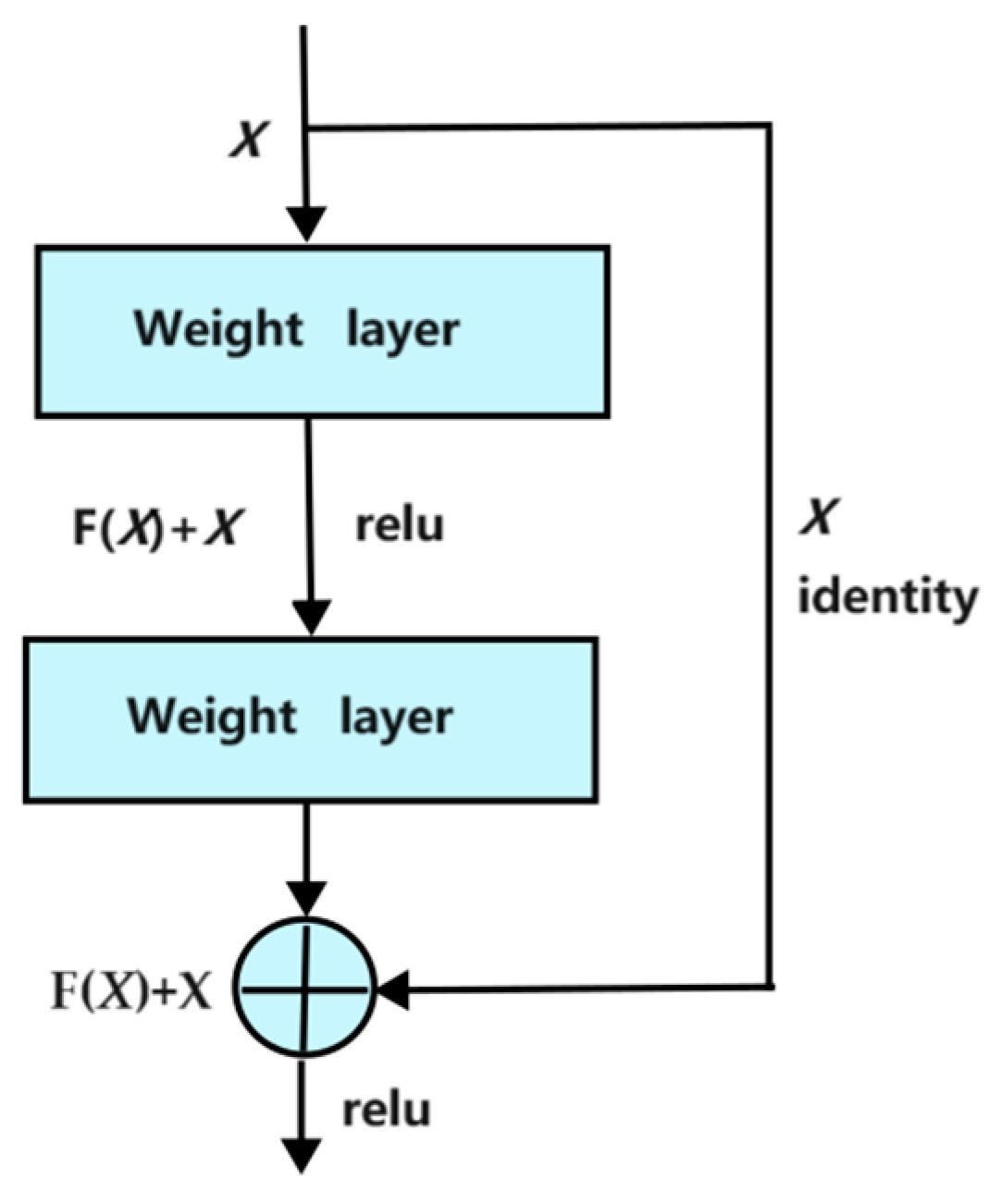
The residual network in the deep network can converge quickly and ensure that the network does not degenerate as the depth increases. Moreover, the difference between the phase unwrapping map and the wrapped phase map has a certain regularity, which is an integer multiple of 2π. The deep residual network is a seemingly simple but extremely effective network structure proposed by Kaiming He in 2015, as shown in the residual block in Figure 1; on the basis of the original ordinary network, there is a shortcut connection between every two layers, H(x) = F(x) + x, constituted by a residual block. Multiple residual blocks are stacked to form a residual network. The practice shows that the deep residual network can improve the performance of the “deep” network effectively.
2.2. U-Net Phase Unwrapping Network
From the network structure of U-net, we could find two main features such as a U-shaped structure and its skip connection. The deeper the network layer, the larger the field of vision of the feature map. The shallow convolution focuses on texture features, and the deep network focuses on the essential features; therefore, the whole network could acquire different level features. In addition, the edges of the larger feature map obtained by deconvolution are lacking in information, as downsampling inevitably loses some edge features and cannot be retrieved from the upsampling. In order to reduce the loss of spatial information caused by the downsampling process, a layer jumping connection is introduced. Through concatenation, the feature map restored by upsampling contains more low-level semantic information, which leads to a better level of detail in the results. Therefore, the edge feature can be retrieved through the splicing of features.
2.3. Neural Network Architecture
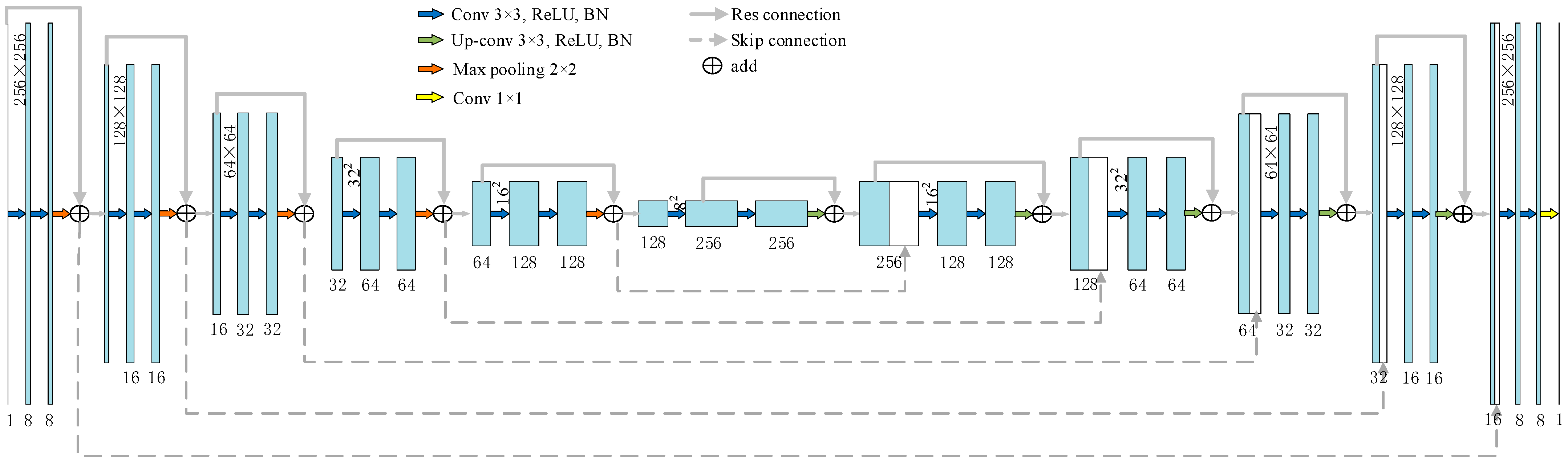
It can be seen from U-net that adding jump connections can increase the depth and improve the accuracy of deep CNNs. We add the skip connection to the model, as shown by the gray dashed line in Figure 2 [24]. For each convolution block, the equation for the skip link is y = F(x) + H(x), where F contains two convolution operations and a max pooling or an upsampling operation, and H is either the same mapping or a convolution operation such that the input has the same feature dimension as F.
2.4. SSIM Loss Function
Loss functions are used to encourage and discourage certain behaviors. In deep learning, if it is a classification problem, loss functions such as cross-entropy, softmax, and SVM can be used. If it is a regression problem, the cost function generally adopts L2 or L1.
L2 (Euclidean distance between the true value and the predicted value) is non-convex and derivable. L2 is used on the premise of a noisy Gaussian distribution, which is able to suppress large errors but has a relatively poor suppression effect on small errors. For example, using L2 can reproduce the edges well, but it cannot eliminate those small noises well. Most importantly, L2 is different from the human visual system (HVS). HVS is heavily sensitive to local information such as light and color changes, and the light sensitivity of cameras made by humans is based on HVS.
The structural similarity index (SSIM) [25] is used to measure the structural similarity between two images. Just like the HVS, the SSIM is sensitive to local structural changes and is derivable. Even when white noise, contrast enhancement, and mean shifting are applied to the image, SSIM does not change significantly.
The SSIM function consists of three parts: illumination, contrast, and structure.
In Equation (6), α, β, γ > 0 to avoid the systematic error caused by the denominator of 0, and c1, c2, c3 are constants. Generally, α = β = γ = 1 and c3 = c2/2. The function F is expressed as
where , , , , and represent the mean and variance of image x, the mean and variance of y, and the covariance of image x and image y, respectively, and and are constants. The default k1 = 0.01 and k2 = 0.03. L is the dynamic range of the pixel value; for example, the L value of an 8-bit depth image is 255.
The larger the SSIM value, the more similar the images are. As a loss function, loss = 1 − SSIM is used. Since Pytorch implements the forward calculation part of SSIM-loss, there is no need to consider the derivation mechanism.
3. Dataset Establishment, Network Training, and Enhancement
3.1. Dataset Establishment
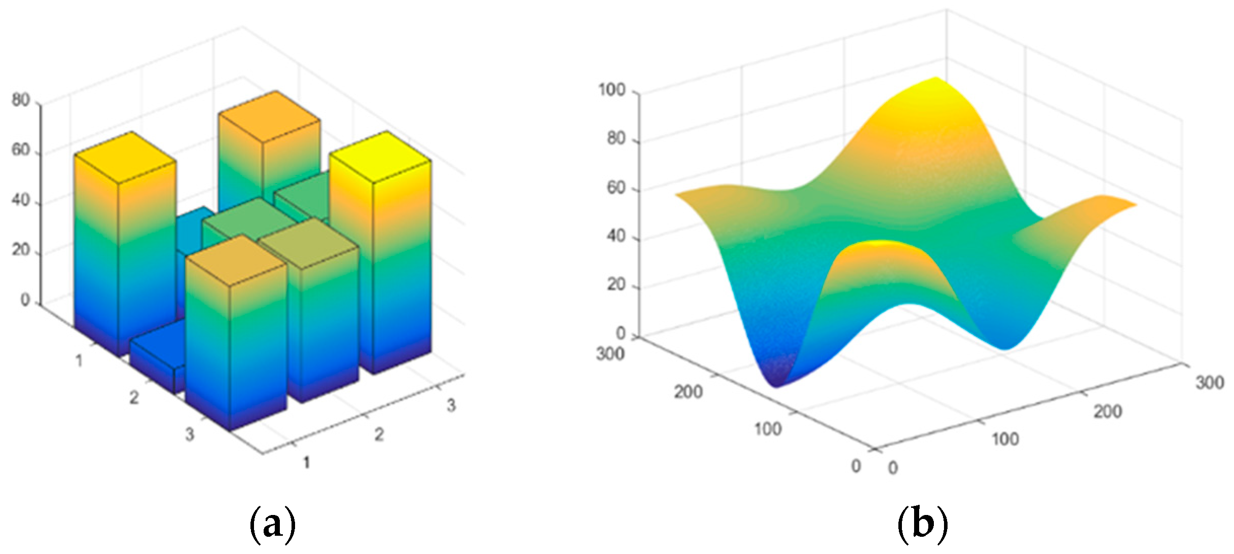
The phase map can be generated in two steps [26]. The first step is the generation of an initial matrix, with a size ranging from 2 × 2 pixels to 4 × 4 pixels. The size of the initial matrix determines the number and location of the extreme points in the final real phase. The range of values (ranging from 2 to 100) of the initial matrix determines the gradient of the final real phase. And the distribution type of the values is a Gaussian-distributed random matrix. The second step involves transforming the matrix into a 256 × 256 matrix through bicubic interpolation. The distribution type of the initial matrix and the interpolation method determine the distribution of the final real phase. Figure 3 shows an example of a real phase generation process. In this experiment, 40,000 sets of images were generated, which were divided into the training image set and validation image set in a ratio of 9:1. Then, noise with a random magnitude (one of Gaussian noise, salt-and-pepper noise, or multiplicative noise) was added to the wrapped phase map of the training image set.
3.2. Network Implementation Details, Tables, and Schemes
The network architecture is implemented using the Pytorch framework version 1.8.0 based on Python 3.6.6. We performed the network training and testing on a PC with a Core (TM) i9-10850K CPU @ 3.60 GHz and 64 GB of RAM, using an NVIDIA GeForce RTX 3090 GPU.
3.3. Network Training Process
As shown in Figure 4, during the training process, the simulated wrapped phase images were fed into the neural network to calculate the outputs. The outputs were then compared with the corresponding ground truth phase images using a loss function, and the parameters and weights of the neural network were updated through backpropagation. The whole process was repeated until the loss function value reached the expected effect and the neural network reached convergence.
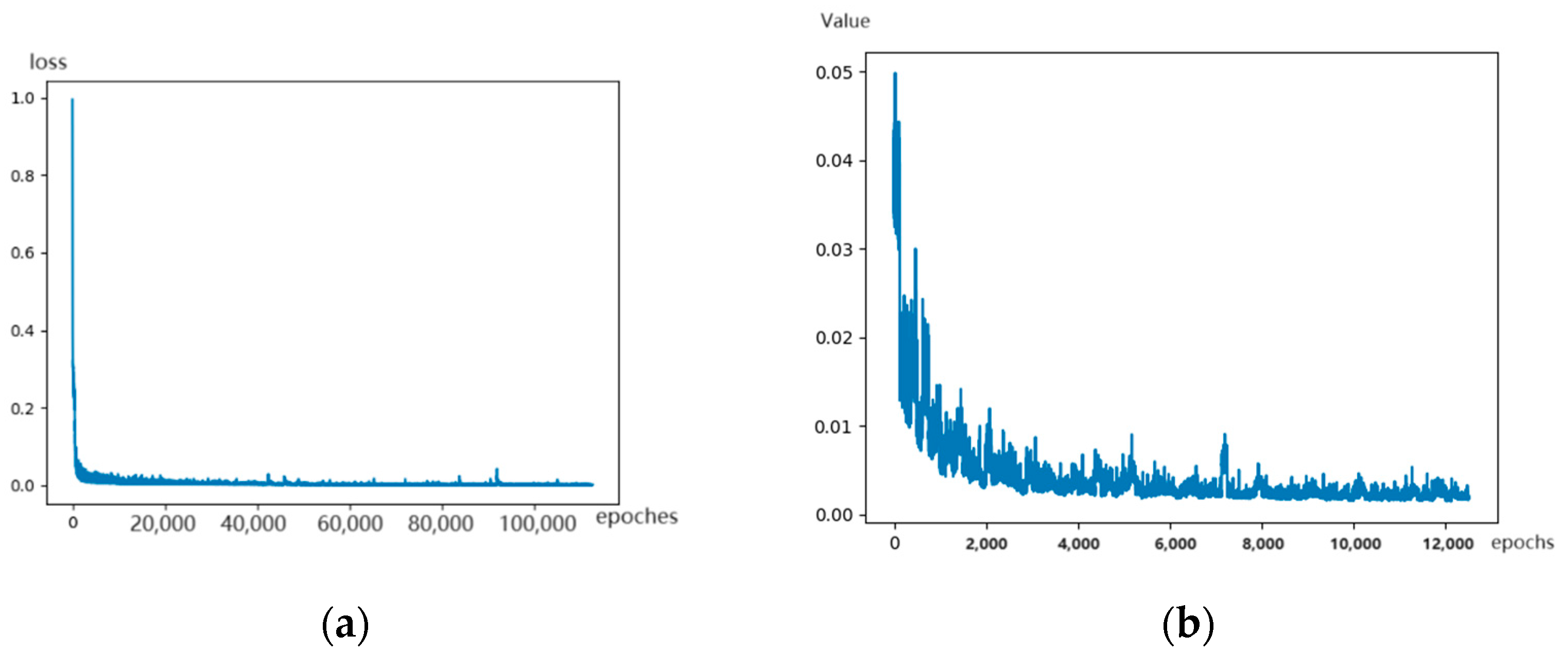
This paper used 36,000 noisy wrapped phase maps as the input of the network, and the corresponding real phase maps were used as real values for network training. In the network training process, the Adam optimization strategy was used, the learning rate was 0.001, the batch size was 32, and the 1-SSIM function was used as the loss function. The loss function of the whole training and validation sets is shown in Figure 5 below. It can be seen that the parameters of the network are close to convergence.
3.4. Image Stitching Function Design
After the training procedure, the network could handle phase maps of arbitrary size, but the unwrapping effect becomes worse as the size of the phase map deviates from 256. Generally, the common methods are downsampling for handling phase maps of larger sizes, as well as interpolation for smaller sizes. But if the fringes of the phase map are dense, downsampling will affect the fringe definition as fringes could disappear. In addition, the network is trained on specific image sizes of 256 × 256, which means that the trained network is the optimal solution under the condition. When the test image size is different from the training size, the network is fixed and may not be the optimal solution for other sizes. This can affect the network’s ability to extract features, and thus it impacts the quality of phase unwrapping.
To make the network have a wider adaptability to the size of the phase map, there are two measures to solve this problem: the image stitching technique or the use of larger-size phase maps to train neural networks. However, considering factors such as the GPU memory and training speed of large-size phase maps, this paper suggests that an algorithm based on phase unwrapping map stitching would be more suitable to deal with this problem.
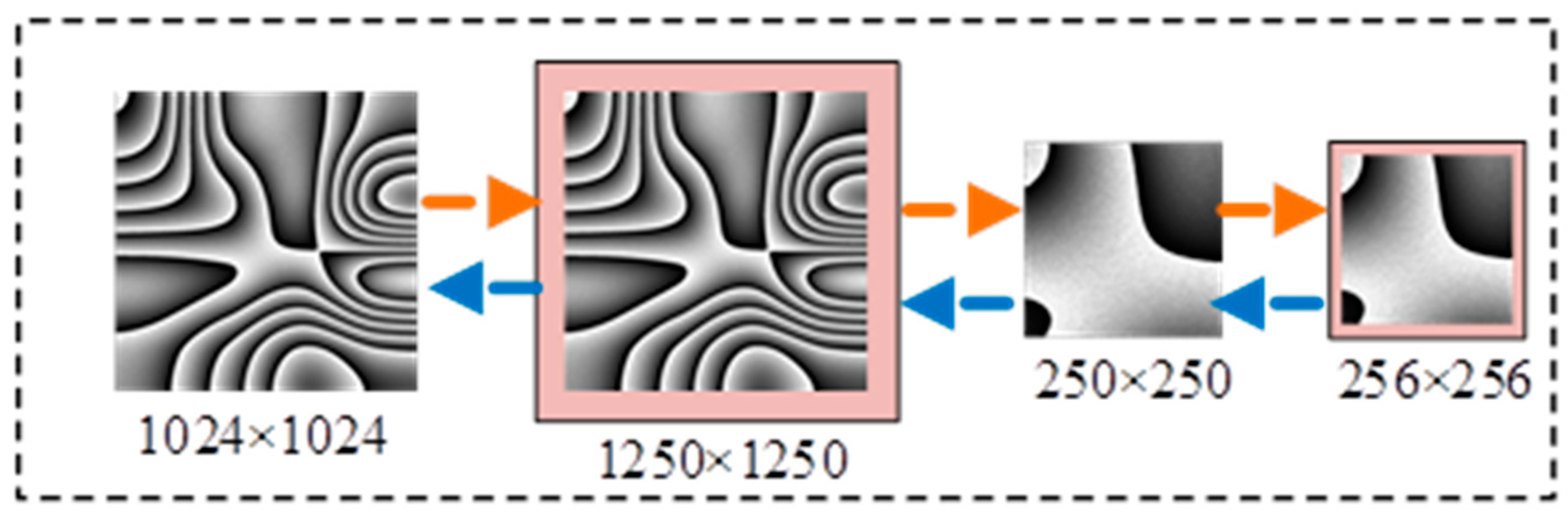
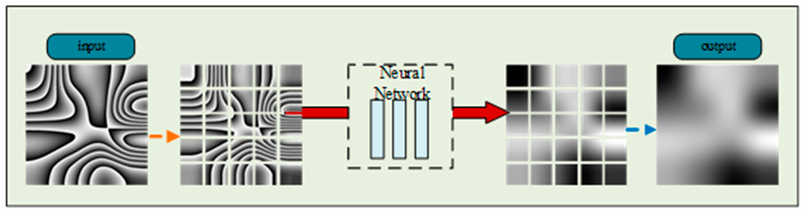
As shown in Figure 6, this section uses a wrapped phase map with a size of 1024 × 1024 pixels to verify the phase unwrapping based on image stitching. First, the wrapped phase map is expanded by edge replication so that its edge length is t times 250, t = min(250 × t − 1024 ≤ 250); then, it is partitioned into t × t small images of size 250 × 250 pixels. Next, each small image is expanded to 256 × 256 by edge replication and input into the neural network to be unwrapped separately. Finally, each small image is merged by inverse operation and restored to the size of 1024 × 1024 to obtain the final unwrapping result. The schematic diagram of the testing process is shown in Figure 7.
4. Experimental Results and Analysis
To test the network’s effectiveness, simulation data and experimental data of phase maps are adopted to represent the ideal and actual state of phase image acquisition, respectively. The results and related analysis are shown as follows:
4.1. Image Results of Simulation and Experimental Data Testing
As shown in Figure 8a,b, two sets of randomly selected photos from the test dataset are depicted. In set Figure 8a, the top image represents real phase maps with added Gaussian noise, while the bottom image represents the corresponding wrapped phase maps. In set Figure 8b, the top image displays real phase maps with added salt-and-pepper noise, with the bottom images representing the corresponding wrapped phase maps.
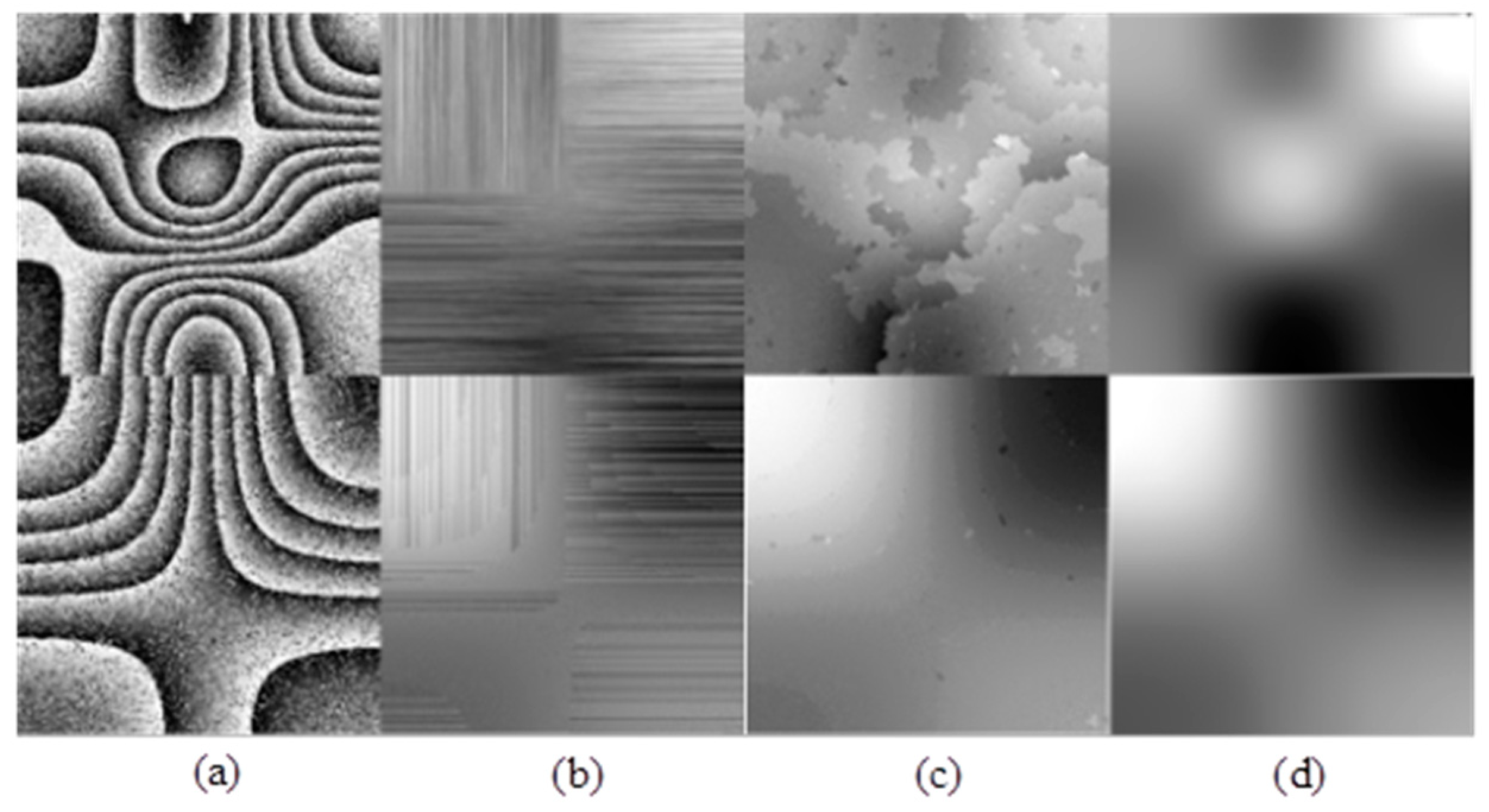
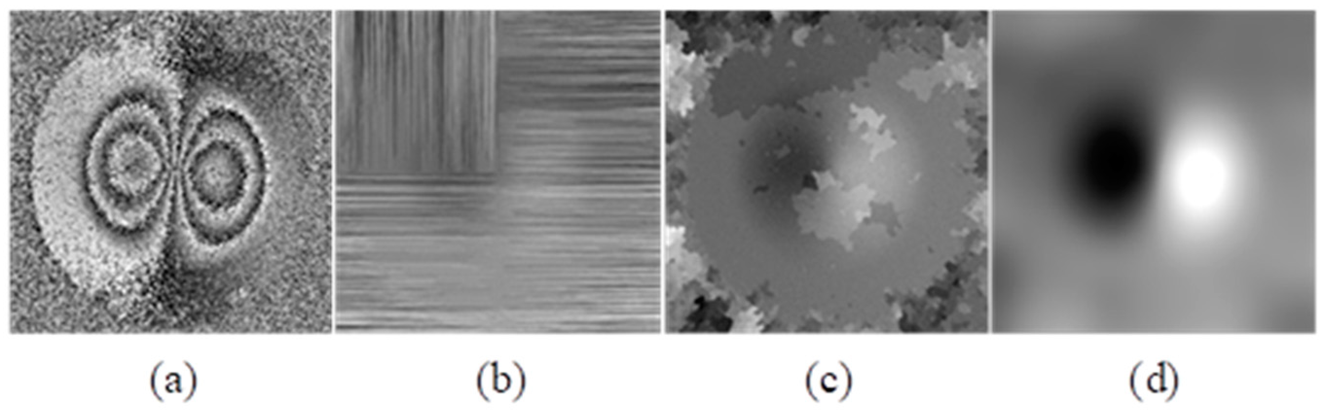
The results of direct unwrapping of the wrapped phase map with noise are shown in Figure 9, in which Figure 9a is the wrapped phase map generated by the simulation with noise added. Figure 9b–d report the results of phase unwrapping by the proposed method, the spiral path algorithm, and the reliability-guided algorithm, respectively.
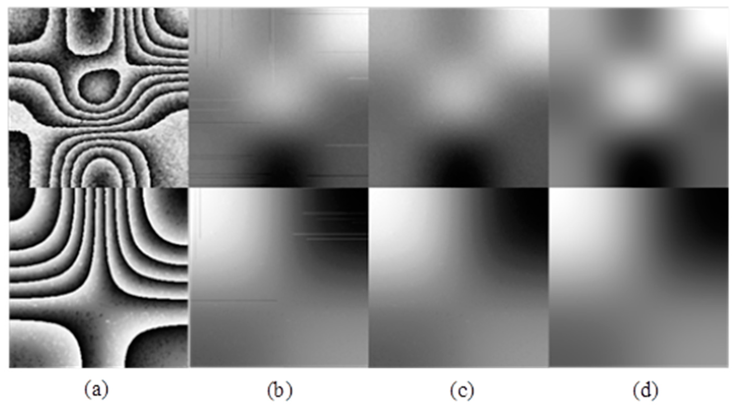
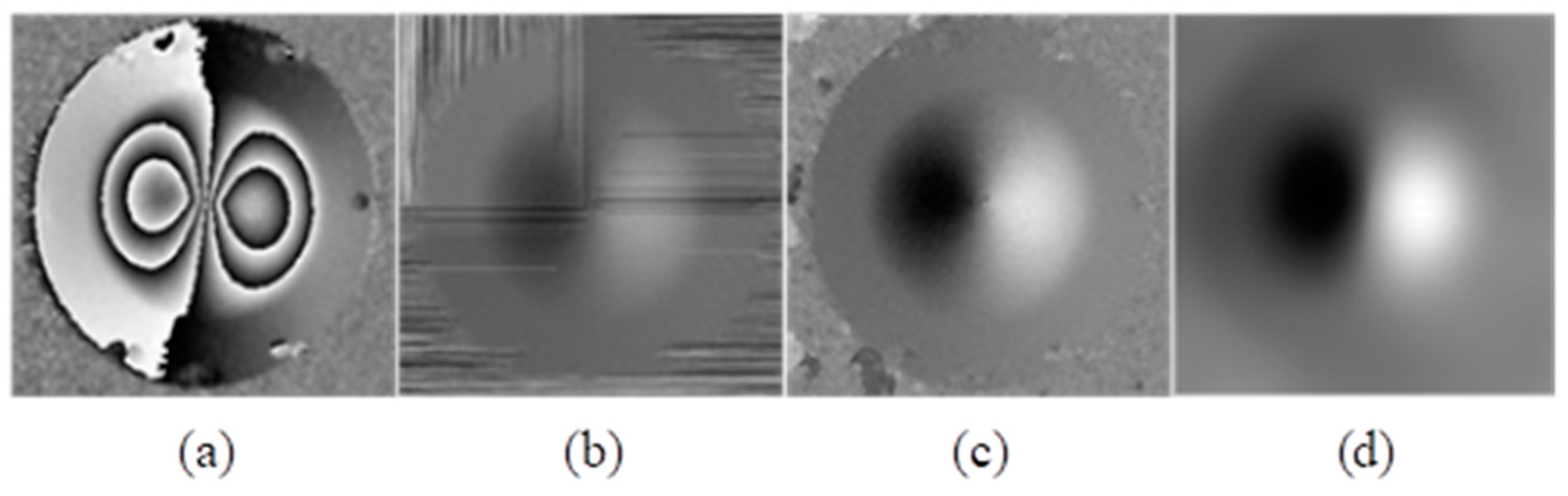
After Gaussian filtering is performed at the top of Figure 10a, and after average filtering is performed at the bottom of Figure 10a, the unwrapping result is shown in Figure 10, where Figure 10a is the wrapped phase map generated by the simulation after denoising; Figure 10b–d, respectively, represent the phase unwrapping results of the algorithm based on the method in this paper, the spiral path algorithm, and the algorithm based on reliability.
Unlike the simulation, the phase map obtained from speckle pattern interferometry often contains a lot of noise, so the anti-noise performance is an important basis for the selection of the unwrapping algorithm. Because the size of the dataset in this paper is 256 × 256, in order to obtain better results, the phase map obtained by the speckle pattern interferometer is downsampled to 256 × 256.
4.2. Result Analysis and Effectiveness Verification
Apart from the image results presented above, the average unwrapping time and SSIM test were performed to verify the effectiveness of the proposed method. The unwrapping time is shown in Table 1.
It can be seen from Table 1 that the algorithm based on reliability guidance has the longest unwrapping time, followed by the algorithm based on the spiral path. The unwrapping time of these two algorithms increases significantly with the increase in image size, and the unwrapping time is proportional to the size of the map to be unwrapped. The unwrapping time of this method for three sizes of images is about 1 s, which is almost not affected by the image size.
From the data in Table 2, we can clearly find that, when unwrapping the wrapped phase maps with a lot of noise, the effects of the algorithm based on the spiral path and the algorithm based on reliability are quite unsatisfactory. After denoising the images, the effect is greatly improved. The Res-unet network has maintained this high level of unwrapping.
To summarize, the experimental results indicate that the unwrapping time of the Res-unet network is independent of the size of the phase map, with an average unwrapping time of about 1 s. Moreover, the unwrapping quality is not affected by the quality of the original phase map. Even if the original phase map contains a large amount of noise, this algorithm can still achieve a high level of unwrapping quality. So, the Res-unet network achieved a good time and precision effectiveness.
5. Conclusions and Discussion
Considering the reality that the unwrapping quality of phase images is affected by the original image quality, and also that the unwrapping time is influenced by the size of the original image, we proposed a neural network for phase unwrapping whose architecture combines residual networks and U-Net networks. We also designed a loss function based on the SSIM function and applied it to the network to improve its precision. Additionally, we adopted the image stitching method to improve the adaptability to the size of the phase maps, instead of training the network with larger image datasets or downsampling the image.
After training the network and testing it with simulation and experimental data, the results indicate that our network not only has strong noise suppression capabilities but also better processing performance regardless of the image size compared with the other two traditional unwrapping algorithms based on the spiral path and reliability.
However, there are still improvements that could be made in our study. For example, the dataset for training the network consists of simulated random speckle patterns. Although the network could study the relationship between wrapped and unwrapped images well, the dataset could be improved further by simulating it from an optical propagation perspective, to make it more closely follow the principles of speckle interferometry and experimental conditions. Furthermore, other neural network models such as GANs and GNNs can be adopted to explore the possibility of better phase unwrapping quality or speed.
Author Contributions
Conceptualization, B.W., C.W. and Y.W.; methodology, Y.W.; software, X.C.; validation, X.C. and M.L.; formal analysis, C.W.; investigation, B.W.; resources, Y.W.; data curation, B.W.; writing—original draft preparation, X.C. and M.L.; writing—review and editing, B.W; visualization, Y.W.; supervision, C.W.; project administration, B.W.; funding acquisition, B.W. All authors have read and agreed to the published version of the manuscript.
Funding
This research was funded by the Infrared and Low-Temperature Plasma Key Laboratory of Anhui Province, grant number IRKL2023KF03, National Natural Science Foundation of China, grant number 52375536, and Hefei Municipal Natural Science Foundation, grant number 2022022.
Institutional Review Board Statement
Not applicable.
Informed Consent Statement
Not applicable.
Data Availability Statement
Data are contained within the article.
Conflicts of Interest
The authors declare no conflicts of interest.
References
- Wang, K.; Kemao, Q.; Di, J.; Zhao, J. Deep learning spatial phase unwrapping: A comparative review. Adv. Photonics Nexus 2022, 1, 014001. [Google Scholar] [CrossRef]
- Marquet, P.; Depeursinge, C.; Magistretti, P.J. Exploring neural cell dynamics with digital holographic microscopy. Annu. Rev. Biomed. Eng. 2013, 15, 407–431. [Google Scholar] [CrossRef] [PubMed]
- An, H.; Cao, Y.; Zhang, Y.; Li, H. Phase-Shifting Temporal Phase Unwrapping Algorithm for High-Speed Fringe Projection Profilometry. IEEE Trans. Instrum. Meas. 2023, 72, 5009209. [Google Scholar] [CrossRef]
- Zhang, Z.; Qian, J.; Wang, Y.; Yang, X. An Improved Least Square Phase Unwrapping Algorithm Combined with Convolutional Neural Network. In Proceedings of the 2021 IEEE International Geoscience and Remote Sensing Symposium IGARSS, Brussels, Belgium, 11–16 July 2021; pp. 3384–3387. [Google Scholar] [CrossRef]
- Chavez, S.; Xiang, Q.S.; An, L. Understanding phase maps in MRI: A new cutline phase unwrapping method. IEEE Trans. Med. Imaging 2002, 21, 966–977. [Google Scholar] [CrossRef] [PubMed]
- Lv, S.; Jiang, M.; Su, C.; Zhang, L.; Zhang, F.; Sui, Q.; Jia, L. Improved unwrapped phase retrieval method of a fringe projection profilometry system based on fewer phase-coding patterns. Appl. Opt. 2019, 58, 8993–9001. [Google Scholar] [CrossRef] [PubMed]
- Goldstein, R.M.; Zebker, H.A.; Werner, C.L. Satellite radar interferometry: Two-dimensional phase unwrapping. Radio Sci. 1988, 23, 713–720. [Google Scholar] [CrossRef]
- Flynn, T.J. Two-dimensional phase unwrapping with minimum weighted discontinuity. J. Opt. Soc. Am. A (Opt. Image Sci. Vis.) 1997, 14, 2692–2701. [Google Scholar] [CrossRef]
- Flynn, T.J. Consistent 2-D phase unwrapping guided by a quality map. In Proceedings of the 1996 International Geoscience and Remote Sensing Symposium ‘Remote Sensing for a Sustainable Future’, Lincoln, NE, USA, 27–31 May 1996; Volume 4, pp. 2057–2059. [Google Scholar] [CrossRef]
- Xu, W.; Cumming, I. A region-growing algorithm for InSAR phase unwrapping. IEEE Trans. Geosci. Remote Sens. 1999, 37, 124–134. [Google Scholar] [CrossRef]
- Schwartzkopf, W.; Milner, T.E.; Ghosh, J.; Evans, B.L.; Bovik, A.C. Two-dimensional phase unwrapping using neural networks. In Proceedings of the 4th IEEE Southwest Symposium on Image Analysis and Interpretation (SSIAI 2000), Austin, TX, USA, 2–4 April 2000; pp. 274–277. [Google Scholar] [CrossRef]
- Dardikman, G.; Shaked, N.T. Phase Unwrapping Using Residual Neural Networks. In Imaging and Applied Optics 2018; OSA Technical Digest; Optica Publishing Group: Washington, DC, USA, 2018. [Google Scholar] [CrossRef]
- Sinha, A.; Lee, J.; Li, S.; Barbastathis, G. Lensless computational imaging through deep learning. Optica 2017, 4, 111711–111725. [Google Scholar] [CrossRef]
- Rivenson, Y.; Zhang, Y.; Günaydın, H.; Teng, D.; Ozcan, A. Phase recovery and holographic image reconstruction using deep learning in neural networks. Light-Sci. Appl. 2018, 7, 17141. [Google Scholar] [CrossRef] [PubMed]
- Spoorthi, G.E.; Gorthi, S.; Gorthi, R.K.S.S. PhaseNet: A Deep Convolutional Neural Network for Two-Dimensional Phase Unwrapping. IEEE Signal Process. Lett. 2019, 26, 54–58. [Google Scholar] [CrossRef]
- Spoorthi, G.E.; Gorthi, R.K.S.S.; Gorthi, S. PhaseNet 2.0: Phase Unwrapping of Noisy Data Based on Deep Learning Approach. IEEE Trans. Image Process. 2020, 29, 4862–4872. [Google Scholar] [CrossRef]
- Liu, K.; Zhang, Y. Temporal phase unwrapping with a lightweight deep neural network. In Proceedings of the SPIE 11571, Optics Frontier Online 2020: Optics Imaging and Display, Shanghai, China, 19–20 June 2020; Volume 11571, p. 115710N. [Google Scholar] [CrossRef]
- Wu, Z.; Wang, T.; Wang, Y.; Ge, D. A New Phase Unwrapping Method Combining Minimum Cost Flow with Deep Learning. In Proceedings of the 2021 IEEE International Geoscience and Remote Sensing Symposium IGARSS, Brussels, Belgium, 11–16 July 2021; pp. 3177–3180. [Google Scholar] [CrossRef]
- Zhou, L.; Yu, H.; Lan, Y.; Xing, M. Deep Learning-Based Branch-Cut Method for InSAR Two-Dimensional Phase Unwrapping. IEEE Trans. Geosci. Remote Sens. 2022, 60, 5209615. [Google Scholar] [CrossRef]
- Chen, X.; Wu, Q.; He, C. Feature Pyramid and Global Attention Network Approach to Insar Two-Dimensional Phase Unwrapping. In Proceedings of the IGARSS 2022-2022 IEEE International Geoscience and Remote Sensing Symposium, Kuala Lumpur, Malaysia, 17–22 July 2022; pp. 2923–2926. [Google Scholar] [CrossRef]
- Sica, F.; Calvanese, F.; Scarpa, G.; Rizzoli, P. A CNN-Based Coherence-Driven Approach for InSAR Phase Unwrapping. IEEE Geosci. Remote Sens. Lett. 2022, 19, 4003705. [Google Scholar] [CrossRef]
- Ye, X.; Qian, J.; Wang, Y.; Yu, H.; Wang, L. A Detail-Preservation Method of Deep Learning One-Step Phase Unwrapping. In Proceedings of the IGARSS 2022-2022 IEEE International Geoscience and Remote Sensing Symposium, Kuala Lumpur, Malaysia, 17–22 July 2022; pp. 1115–1118. [Google Scholar] [CrossRef]
- Yang, K.; Yuan, Z.; Xing, X.; Chen, L. Deep-Learning-Based Mask-Cut Method for InSAR Phase Unwrapping. IEEE J. Miniaturization Air Space Syst. 2023, 4, 221–230. [Google Scholar] [CrossRef]
- Xiao, X.; Lian, S.; Luo, Z.; Li, S. Weighted Res-UNet for High-Quality Retina Vessel Segmentation. In Proceedings of the 2018 9th Interna-tional Conference on Information Technology in Medicine and Education (ITME), Hangzhou, China, 19–21 October 2018; pp. 327–331. [Google Scholar] [CrossRef]
- Wang, Z.; Bovik, A.C.; Sheikh, H.R.; Simoncelli, E.P. Image quality assessment: From error visibility to structural similarity. IEEE Trans. Image Process. 2004, 13, 600–612. [Google Scholar] [CrossRef] [PubMed]
- Wang, K.; Li, Y.; Kemao, Q.; Di, J.; Zhao, J. One-step robust deep learning phase unwrapping. Opt. Express 2019, 27, 15100–15115. [Google Scholar] [CrossRef] [PubMed]
Figure 1.
Residual block.

Figure 2.
Detailed schematic of the neural network architecture.

Figure 3.
Example of the random square matrices and the corresponding generated real phases. (a) Initial matrix. (b) real phase.
Figure 3.
Example of the random square matrices and the corresponding generated real phases. (a) Initial matrix. (b) real phase.

Figure 4.
The illustration of training process.

Figure 5.
Loss value curve of phase unwrapping network. (a) The loss curve for the training set. (b) The loss curve for the validation set.
Figure 5.
Loss value curve of phase unwrapping network. (a) The loss curve for the training set. (b) The loss curve for the validation set.

Figure 6.
Image cropping and merging.

Figure 7.
Schematic diagram of the testing process.

Figure 8.
The two sets of simulated data. (a) The real phase map and wrapped phase map with Gaussian noise; (b) The real phase map and wrapped phase map with salt and pepper noise.
Figure 8.
The two sets of simulated data. (a) The real phase map and wrapped phase map with Gaussian noise; (b) The real phase map and wrapped phase map with salt and pepper noise.

Figure 9.
Phase unwrapping results of images containing noise. (a) The wrapped phase map generated by the simulation with noise added; (b) The results of phase unwrapping by the proposed method (c) The results of phase unwrapping by the spiral path algorithm; (d) The results of phase unwrapping by the reliability-guided algorithm.

Figure 10.
Phase unwrapping results of images after filtering. (a) The wrapped phase map generated by the simulation after denoising; (b) The result of phase unwrapping by the proposed method after denoising (c) The result of phase unwrapping by the spiral path algorithm after denoising; (d) The result of phase unwrapping by the reliability-guided algorithm after denoising.

Figure 11.
Phase unwrapping results of images containing noise. (a) The wrapped phase map obtained by the speckle pattern interferometer; (b) The effect after unwrapping by the algorithm based on the spiral path; (c) The effect after unwrapping by the algorithm based on reliability; (d) The effect after unwrapping by the Res-unet.

Figure 12.
Phase unwrapping results of image denoising. (a) The wrapped phase map obtained from the speckle interferometer after applying a denoising technique; (b) The effect after unwrapping by the algorithm based on the spiral path; (c) The effect after unwrapping by the algorithm based on the spiral path; (d) The effect after unwrapping by the Res-unet.


Table 1.
Average unwrapping time of different phase unwrapping algorithms (unit: s).
| Unwrapping Method | 256 × 256 | 512 × 512 | 1024 × 1024 |
|---|---|---|---|
| Algorithm based on spiral path | 0.21 | 0.24 | 0.4237 |
| Algorithm based on reliability | 0.31 | 6.5 | 74.84 |
| Res-unet | 1.087 | 1.085 | 1.169 |
Table 2.
SSIM value between results of different unwrapping algorithms and the unwrapped phase.
| Unwrapping Method | Figure 8a | Figure 8a after Denoising | Figure 8b | Figure 8b after Denoising |
|---|---|---|---|---|
| Algorithm based on spiral path | 0.3069 | 0.8933 | 0.4237 | 0.9312 |
| Algorithm based on reliability | 0.5947 | 0.9797 | 0.8499 | 0.9828 |
| Res-unet | 0.9876 | 0.9876 | 0.9932 | 0.9936 |
Disclaimer/Publisher’s Note: The statements, opinions and data contained in all publications are solely those of the individual author(s) and contributor(s) and not of MDPI and/or the editor(s). MDPI and/or the editor(s) disclaim responsibility for any injury to people or property resulting from any ideas, methods, instructions or products referred to in the content. |
© 2024 by the authors. Licensee MDPI, Basel, Switzerland. This article is an open access article distributed under the terms and conditions of the Creative Commons Attribution (CC BY) license (https://creativecommons.org/licenses/by/4.0/).
Share and Cite
MDPI and ACS Style
Wang, B.; Cao, X.; Lan, M.; Wu, C.; Wang, Y. An Anti-Noise-Designed Residual Phase Unwrapping Neural Network for Digital Speckle Pattern Interferometry. Optics 2024, 5, 44-55. https://0-doi-org.brum.beds.ac.uk/10.3390/opt5010003
AMA Style
Wang B, Cao X, Lan M, Wu C, Wang Y. An Anti-Noise-Designed Residual Phase Unwrapping Neural Network for Digital Speckle Pattern Interferometry. Optics. 2024; 5(1):44-55. https://0-doi-org.brum.beds.ac.uk/10.3390/opt5010003
Chicago/Turabian StyleWang, Biao, Xiaoling Cao, Meiling Lan, Chang Wu, and Yonghong Wang. 2024. "An Anti-Noise-Designed Residual Phase Unwrapping Neural Network for Digital Speckle Pattern Interferometry" Optics 5, no. 1: 44-55. https://0-doi-org.brum.beds.ac.uk/10.3390/opt5010003