
Practical Demonstration of 5G NR Transport Over-Fiber System with Convolutional Neural Network


School of Engineering, Ulster University, Newtownabbey BT37 0QB, UK
Telecom 2022, 3(1), 103-117; https://0-doi-org.brum.beds.ac.uk/10.3390/telecom3010006
Submission received: 28 December 2021
/
Revised: 24 January 2022
/
Accepted: 27 January 2022
/
Published: 2 February 2022
(This article belongs to the Special Issue Advances in Optical Wireless Communication)
Abstract
:This study describes an experimental realization using digital predistortion (DPD) for a fifth generation (5G) multiband new radio (NR) optical front haul (OFH) based Radio over Fiber (RoF) link. For the performance enhancement and complexity reduction of RoF links, a novel Convolutional Neural Network (CNN) based DPD technique is proposed, followed by comparisons with the generalised memory polynomial (GMP) based DPD method. To support enhanced mobile broad band scenario, the experimental testbed uses the 5G NR waveforms at 10 GHz with 20 MHz bandwidth and a flexible-waveform signal at 3 GHz with 20 MHz bandwidth. For 10 km of typical single mode fiber, a Mach Zehnder Modulator with two distinct radio frequency waveforms modulates a 1310 nm optical carrier utilizing distributed feedback laser. The error vector magnitude and number of estimated coefficients, and multiplications are all used to describe the experimental outcomes. The goal of the research is to see if CNN-based DPD improves performance while lowering complexity levels to meet 3GPP Release 17 criteria.
1. Introduction
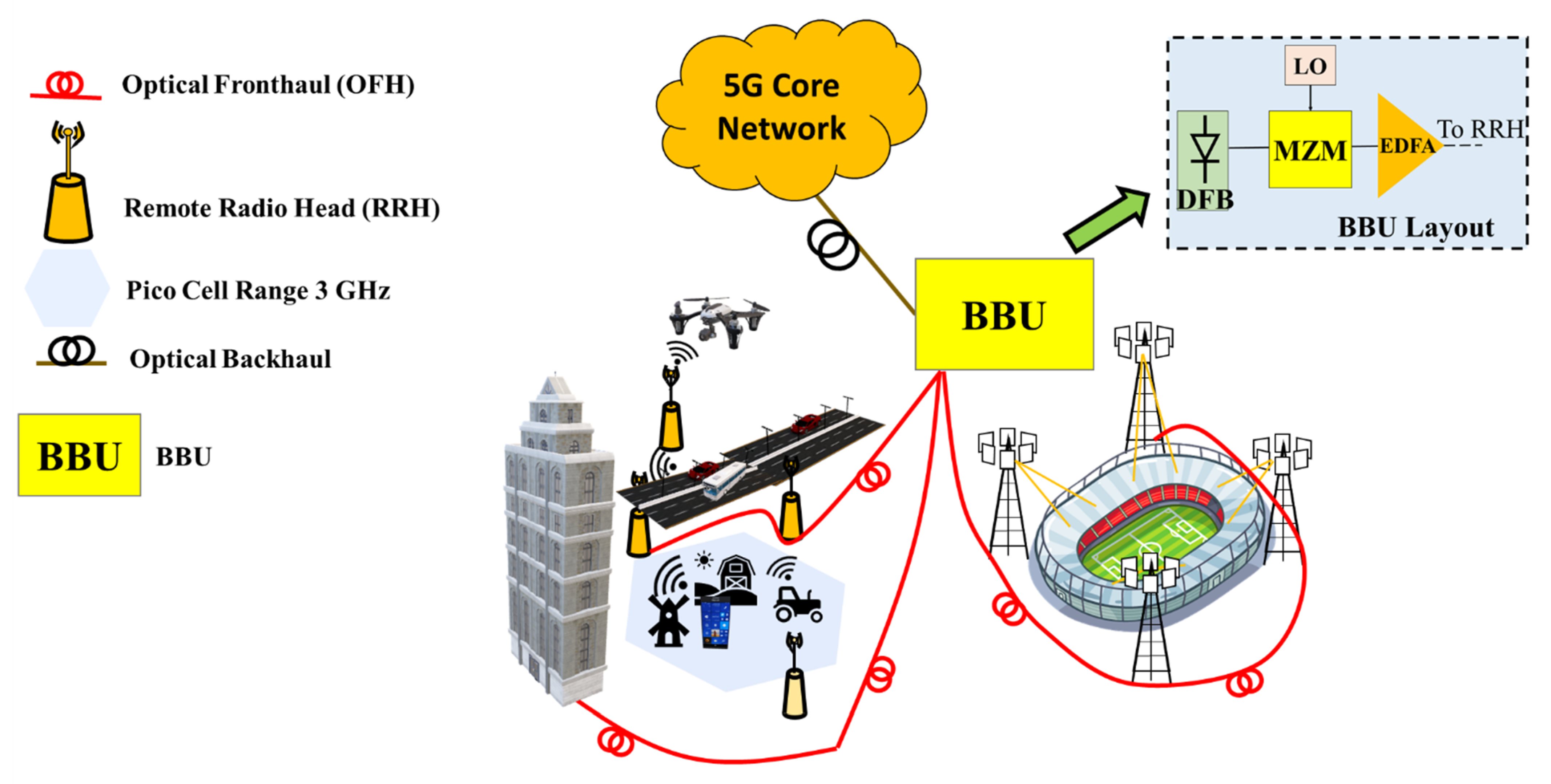
With major developments in the fifth generation known as 5G and beyond 5G, the centralization of radio access network (RAN) has been established due to the ever increasing rate of base stations (BS) [1], which decreases capital expenditure by simplifying network management [2]. An optical fronthaul (OFH/FH) simply connects the base band units (BBU) to remote radio heads (RRH) to facilitate C-RAN (see Figure 1). Due to unlimited benefits and increase in wireless link reach for all kinds of applications such as short to long link applications, microwave photonics-based solutions such as Radio over Fiber (RoF) have a higher significance connecting the BBUs with RRUs [1,2] with 5G in the operational stage in most parts of the world [1,2].
Various RoF variants have been proposed in recent years, including Analog Radio over Fiber (A-RoF) [1,2,3,4,5], Digital transport over Fiber (D-RoF) [6,7,8,9], Sigma Delta transport/Radio over Fiber (SD-RoF) [10,11,12], and others (see Figure 2). A-RoF links are, to some extent, the simplest and most cost-effective option; nonetheless, they suffer from nonlinearities generated from signal impairments and components such as laser modules, fiber, and photodiodes. Using D-RoF or SD-RoF is one of the alternative options.
When it comes to D-RoF systems, the analogue to digital (ADC) and digital to analogue (DAC) required make the process exceedingly costly. Furthermore, common public radio interface (CPRI) restrictions exist due to high data rate capacity and limited bandwidth. The SD-RoF can be used to bypass the CPRI bottleneck. ADCs and DACs aren’t needed because the method is based on sigma-delta modulation, which only uses one bit of ADC. However, the method is difficult, thus it’s not recommended. Furthermore, because the quantization noise is significant for 1 bit, an extra band pass filter (BPF) at the RRH is required. However, this added complexity is not the only issue that needs to be addressed for S-DRoF implementation; the addition of BPF introduces additional noise in amplitude and phase, which necessitates a second method to remove these nonlinearities [13].
It is clear that utilising alternative techniques (D-RoF/SD-RoF) is time, resource and power consuming. As a result, the A-RoF systems are the preferable alternative for optical fronthaul due to their legacy, infrastructure, and cost-effectiveness (OFH). Mitigating nonlinearities in RoF transmission is critical for maximising the system’s potential and has become worthy of discussion. To address the widespread challenges in all of these distinct fields, a variety of strategies have been employed. The ones widely used are mentioned in Section 2 under the literature review.
As transmission quality diminishes, the laser nonlinearities become more significant. When it comes to long-range networks, however, nonlinearities caused by a combination of fiber dispersion and laser chirp are frequently the primary cause of impairments and degradation [7]. Due to the high peak-to-average power ratio (PAPR), Orthogonal Frequency Division Modulated (OFDM) signals, such as the highlighted 5G transmission, are also susceptible to similar distortions, i.e., PAPR.
This study introduces nonlinear behavior and signal degradation compensation for OFH based RoF systems using 5G NR based RoF technology, to the best of the authors’ knowledge. The novelty of this study is numerous, following a thorough literature assessment on nonlinearity mitigation in Section 2:
- In the experimental testbed, multiband 5G NR signals are used to cover enhanced mobile wide band (eMBB) scenarios and small cells for 3 GHz and 10 GHz, respectively.
- An abled DPD method based on a Convolutional Neural Network (CNN) is proposed and demonstrated. In comparison to existing learning architectures, the proposed DPD identification approach has a better performance and lower complexity than our previous machine learning approach.
- Finally, a simple CNN-based DPD algorithm is proposed as an upgrade to our previously published DPD-based technique based on deep learning for 20 MHz with 5G New Radio (NR) based RoF links. A new sort of training is used to implement the CNN DPD technique, which does not use In-direct Learning Architecture (ILA). We first use an RoF CNN to simulate the generic RoF connection and then use this to train the proposed DPD CNN by backpropagating the mistakes.
- A comparative experimental investigation was conducted in which the previously proposed ILA-based GMP method was benchmarked against the CNN technique and compared utilising a 5G NR multiband signal. Error Vector Magnitude (EVM) and multiplications and coefficients required measuring complexities are used to evaluate the performance.
2. Literature Review
In this section, only Machine Learning Methods are used to discuss the linearization methodologies that have been inferred for the RoF systems. Linearization of OFH has been a significant research area as summarized below in Table 1. There has always been a drive to have better linearization to get higher performance that has shifted the focus towards Machine Learning (ML). ML being the new avenue is the core discussion of this work so a recent literature review has been discussed for all methods with specific importance to machine learning methods. For the reduction of the RoF system impairments, a thorough literature review is described in Table 1. The table outlines the method used, the type of linearization used, the category, the parameters examined, and the benefits and drawbacks of each method.
3. Convolutional Neural Network Architecture
Convolution Neural Networks (CNN) are advanced networks that, like the recommended NN-based DPD model, require a large amount of training data. The RoF link is then cascaded with this model, but the outcome is unknown. However, because the output of an RoF connection is known, we create an RoF NN model and train it to mimic the original RoF link. We can now backpropagate through this RoF CNN and adjust the parameters in the recommended CNN DPD model after we have formulated it.
The convolutional layer is the first layer of a CNN. With the help of a kernel, it extracts features from input data and outputs a feature map (convoluted data).
The kernel or filter (kernel matrix), input data (input matrix), and feature map are all components of a convolutional operation.
Assuming the examined RoF link has H(n) function and as an output signal, and that a baseband signal must be delivered over it where , DPD tries to calculate the inverse transfer function of this RoF link, represented by
, whose output is then indicated by .
This can be written as:
while,
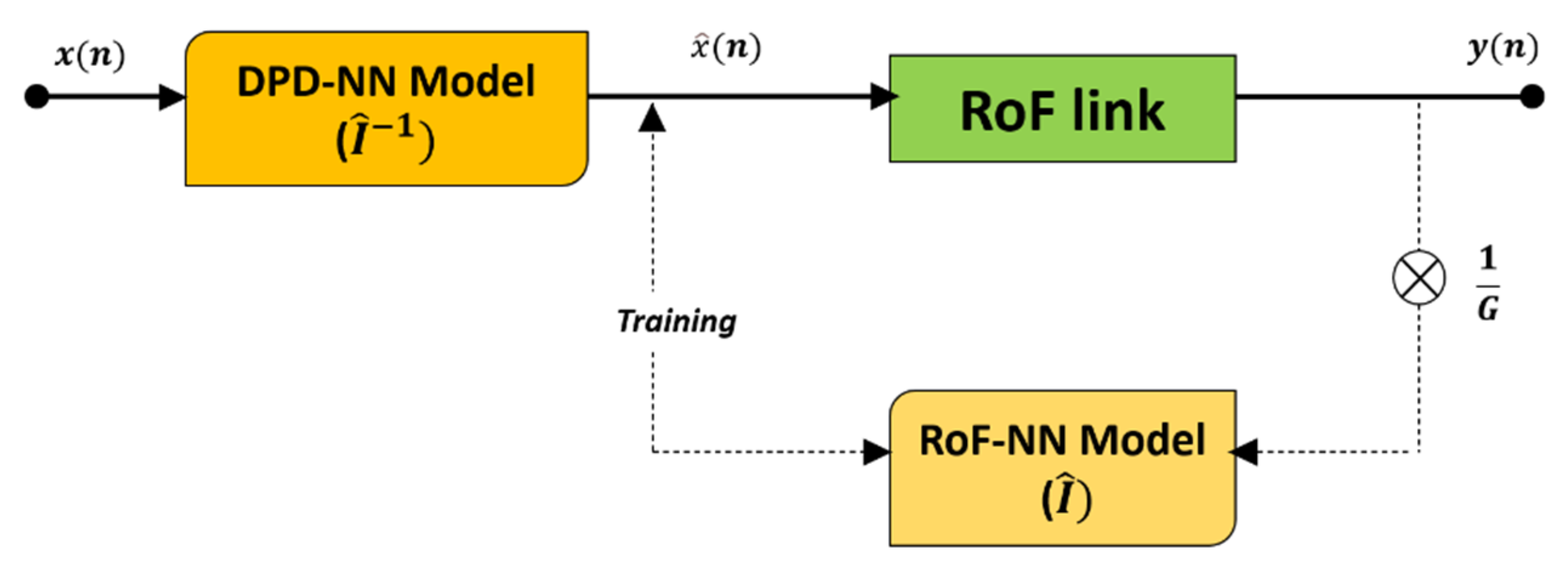
as G represents the gain. The CNN here finds out the utilized for predistortion. A direct training cannot be done for establishing the CNN for DPD as the ideal is not known as illustrated in Figure 2.
Initially, the second CNN simulates the RoF link. Here, is an input and as output for a generic RoF link. This leads to the CNN learning, and it can now identify an approximate transfer function . The model weights are fixed once the RoF CNN model is formed, and then it is connected to the CNN DPD model. To calculate error using a loss function, we now use the original input, and output as training data. We then backpropagate it through to train .
3.1. CNN Model Salient Features
This section will go through all the characteristics of CNN that are required for use in a DPD-based RoF system. The characteristics that make a CNN model are discussed in this section one by one. These characteristics serve as a foundation of the successful implementation of the CNN.
3.1.1. Optimizer
The Adam algorithm amalgamates the Momentum and RMS functions, which means that it keeps an exponentially decaying average of prior squared gradients as well as an exponentially decaying average of previous gradients. Due to the component of speed and the ability to adjust gradients, Adam is an effective optimizer. This is also why it is the most commonly utilised optimizer. ADAM has outperformed the competition, particularly in terms of convergence speed, which is why it is the most widely used and efficient optimizer.
3.1.2. Activation Functions
A node’s capacity is not defined apriori. The activation helps to deduce it. It accomplishes this by establishing a relationship between the node’s various weights and biases and then applying the relationship to the node as a function, so generating responses. It also assists it in learning complex data patterns. They convert the node’s incoming signals into an output signal that will either be used in the network’s next layer or will be the output. In contrast to the gradient of sigmoids, which grows smaller as the absolute value of gradient increases, the chance of a vanishing gradient is lesser when considering ReLu. ReLu has a constant gradient, which aids learning and makes it the better choice.
3.1.3. Regularization
CNN with high learning parameters and sparse or noisy training data are prone to overfitting problems. Overfitting occurs when a model improves its performance on training data but fails to classify fresh test instances that are part of the same domain problem. We employed an L2 regularization approach to avoid this problem.
In this method, a regularization term is taken into account when updating the cost function. This regularization term reduces the value of the weight matrices by resulting in a simpler model, minimizing the problem of overfitting greatly.
In L2, we have:
where w is weight and λ is the regularization parameter (which is adjusted for more exact results). The L2 method is known as a decay approach for updating weights because it forces the weights to decay towards zero, though they never reach zero exactly.
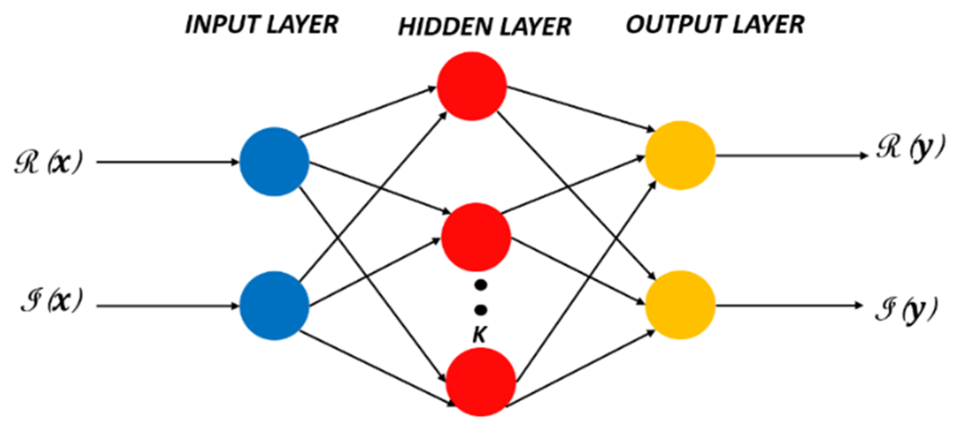
We have developed a foundation of all components of a CNN, the DPD CNN, which was used to distort the RoF system, and the replicated RoF CNN, which is needed for training this DPD CNN, based on the conversation so far. The CNN used here is a feedforward fully connected network with N hidden layers and K neurons per hidden layer. Figure 3 depicts the symbolic structure of the employed CNN. Due to the complex nature of baseband signals, which represent both the real and imaginary components of the signal, the CNN has two inputs and two outputs. At least one of the several hidden levels has been activated using the ReLu function (owing to its lower complexity).
The O/P for the primary layer (hidden) is represented:
where, l1 represents the primary hidden output layer, is the nonlinear function of activation and is the weight and is the bias for the first output layer in the network.
The general output for the ith layer is represented as:
where, .
After N hidden layers, the ultimate result will be:
3.1.4. Training Algorithm
The CNN DPD model was trained using the following algorithm. Mean Square Error (MSE) is employed as the loss measuring function, ADAM is used for the optimization, ReLu is used as activation function and backpropagation is used to update the weights. To improve the performance, Z number of iterations are used.
As previously stated, we use the input and the output of the original RoF connection to train our emulated RoF CNN model, and after this model is acquired, we connect the CNN DPD model to it. Then, once this training is complete, we attach the actual RoF link to this DPD CNN and begin the predistortion process (see pseudocode in Algorithm 1). It is shown in the algorithm that the CNN is made on with updates on followed by the pre-distortion functionality usage in terms of as shown in Figure 2.
| Algorithm 1. Training for linearization (DPD) |
| ←
for i Z do ← : //Radio over Fiber -Transmission ← Train on , //Update Radio over Fiber CNN //Fixed NN weights of ← Train on . //Utilize () ← : //Predistort end for |
4. Experimental Setup
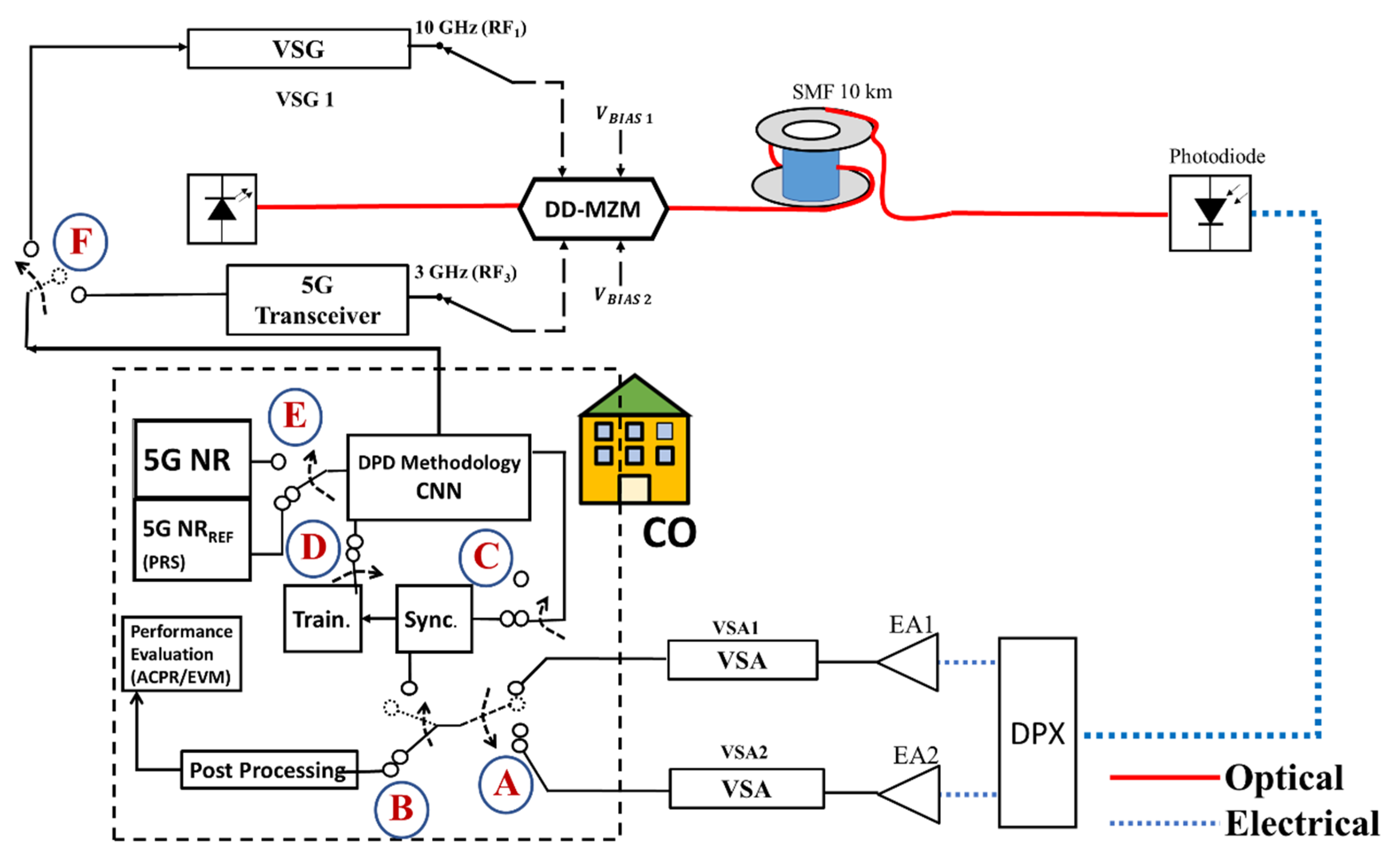
A scenario comprising of multiband 5G NR at 3 GHz (20 MHz) and 10 GHz (20 MHz), which was mentioned in our prior work [54], was used to validate this technique, but no DPD was used. As an upgrade to this architecture, a multiband DPD block has been added to this arrangement to improve the speed of this link. A dual drive Mach Zehnder Modulator (MZM) operating with two separate RF-driven signals, and a 1310 nm DFB laser is used in the system depicted in Figure 11. The Vector Signal Generator (VSG) labelled as VSG1 transmits RF1, a 5G NR waveform at 10 GHz, while the 5G transceiver transmits RF2, a 3 GHz flexible waveform signal. The DPD process can be broken down into three stages.
At first, these signals undergo up-conversion one by one at their respective carrier frequencies of 3 and 20 GHz, respectively, before passing them through 10 km of Standard Single-Mode Fiber (SSMF) and receiving them with a photodetector (0.71 A/W) that receives the signal and converts it back to the electrical domain. An amplification step is introduced since the multiband needs to be separated independently. The 10 GHz and 3 GHz signals are separated using a diplexer (DPX). After that, the signals are sent to several vector signal analyzers (VSA). For performance evaluation, each VSA output is passed to the post-processing block. This phase is done without DPD, which means the output is evaluated without going through the DPD process.
The DPD method represented in Figure 4 is used in the second phase, referred to as the DPD training phase, and training is used until the error converges.
To put it another way, DPD validates the theory behind inverting the amplitude and phase responses obtained at electrical amplifiers EA1 and EA2. CNN methods can be used depending on the user’s needs and comparative requirements.
We use the PRS (positioning reference signal) given in the 5G NR architecture to accomplish synchronization for the received waveforms (both, input and output). PRS is assumed to have a bandwidth of 20 MHz/106 resource blocks. In the time domain, the received and output reference broadcast signals are correlated, and the PDP (power delay profile) is processed through the maximum block to determine the strongest path of arrival.
In the third step, the pre-distorted baseband signals are fed into the DPD block, where they are upconverted to their carrier frequency by their respective VSGs before being fed onto the optical connection. The signal obtained at the photodiode is then transmitted through a diplexer DPX to isolate the various multi-bands before being sent to the DPD training step. We flip the switches in the opposite direction during the DPD validation step. The evaluation for 5G NR frames is completed by predistortion and then transferring the frames to the VSG. Because the nonlinearities of the RoF link slowly change due to thermal impacts and component ageing, we conclude that real-time operation in the adaptation is unnecessary. Table 2 summarizes the parameters employed, which have previously been used in [1,2] and other state-of-the-art [54,55] studies.
Table 3 displays the CNN parameters that result in NN performance that is optimised. Table 3 lists the parameters that define the architecture of the intended Convolutional Neural Network. The parameter selection is done by a trial-and-error test [1]. The table’s final section assesses the NN’s complexity by computing its expressions in terms of its coefficients.
5. Results and Discussion
The results for the experimental setup outlined in the previous part are discussed in this section. The Mean Square Error (MSE) is one of the methods for estimating the accuracy of coefficient estimation for various architectures. From our previous work, GMP and Magnitude Selective Affine (MSA) DPD methods results are used to compare with our proposed CNN method. When no DPD is used, the MSE is 27 dB, while GMP has 30 dB. For Canonical Piecewise Linearization (CPWL) and MSA, the value drops to 35 dB, whereas CNN has an MSE of 39 dB.
The proposed approach is compared and reported in the form of Error Vector Magnitude (EVM). From our recent work [2], we just use GMP methods as a baseline architecture to compare with our proposed CNN method.
Error Vector Magnitude
The most common performance indicator utilised in 3GPP for this research item’s performance evaluation is Error Vector Magnitude. The difference between the symbol’s demodulated ‘anticipated’ value and the demodulated received symbols ‘real’ value is determined by EVM. EVM can be expressed as [5,55]:
where is the number of constellation symbols, denotes the constellation’s real symbol associated with the symbol “” and is the real symbol associated with . The EVM limit for 3GPP using 256 QAM is 3.5% [56].
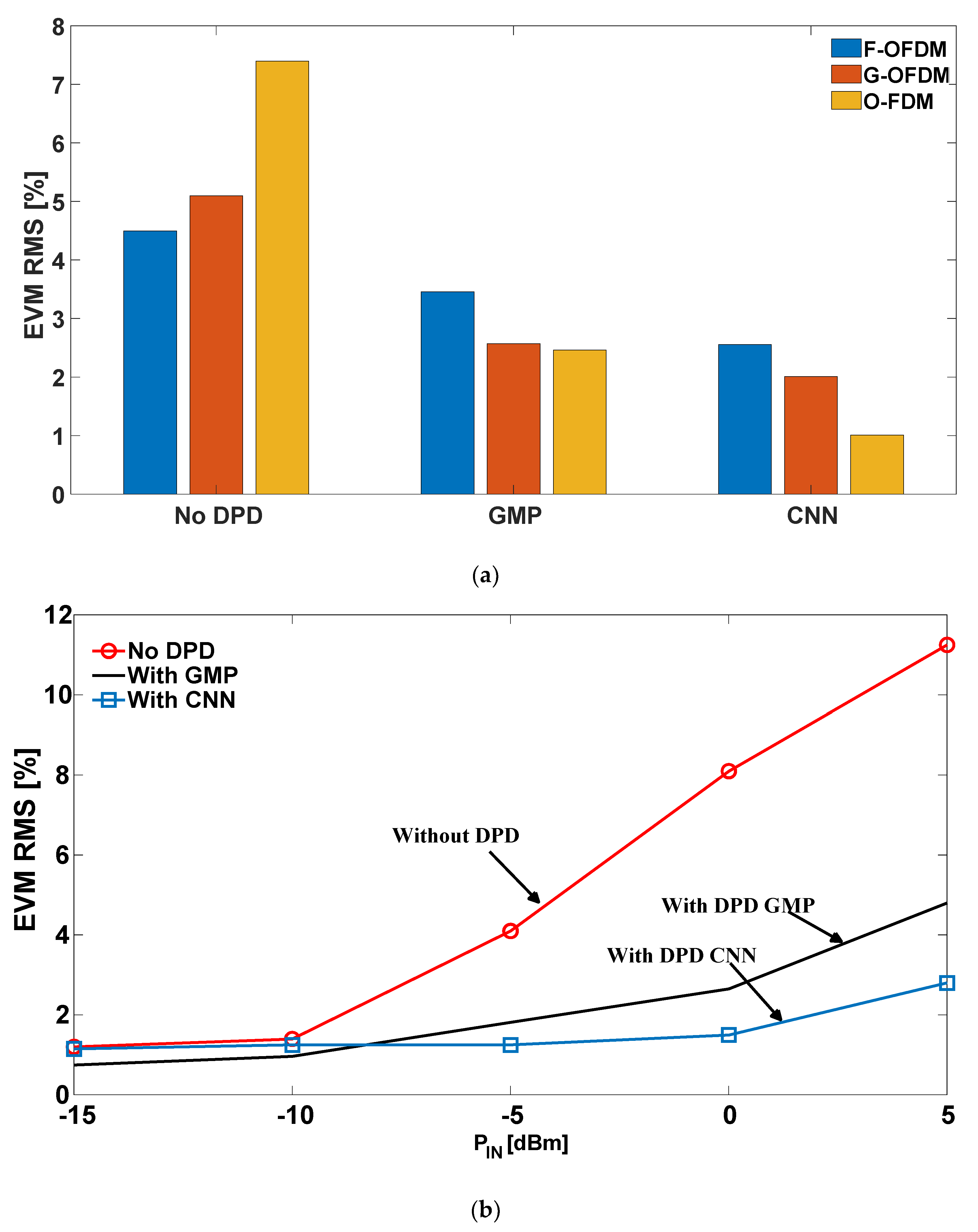
In Figure 5a, the Error Vector Magnitude EVM is represented for flexible waveforms compared for the case when there is no DPD improvement procedure employed when GMP DPD method is employed, and the CNN DPD method is utilized. It is observable that the CNN DPD method results in a better reduction as compared to GMP for all the flexible waveform architectures. Similarly in Figure 5b, it can be seen that when the RF input power is varied, the reduction in EVM due to the proposed CNN method is much better as compared to GMP method. For a high RF input power of 5 dBm, DPD CNN reduces EVM to approximately 2% while GMP has EVM around 5% so EVM reduction is about 9% with the CNN method bringing the performance within the limits set by 3GPP.
6. Complexity Considerations
By lowering complexity and attaining equivalent performance to the DNN approach outlined in prior work [2], CNN-DPD achieves a significant improvement. Table 4 depicts the difficulty of creating a DPD model, which is mostly determined by the number of actual multipliers necessary, as multipliers use the majority of the hardware resources. MSA DPD (220 multiplications) is significantly less complicated than CPWL, as seen in Table 4. (880 multiplications). More complex versions can be constructed by increasing the memory depth Q and nonlinearity order K in the Volterra series. However, the computational complexity must be considered. This means that while choosing the DPD model and its complexity, a reasonable trade-off between complexity and performance may be made.
For a comprehensive review of CNN and Volterra techniques in the manner of complexity, Table 4 summarizes the complexities for the methods. CNN complexity is a challenging problem to solve, however as shown in this work, it can be reduced by employing a minimal number of N and K.
Indeed, with the higher modulation format and higher bandwidth similar to multiple LTE carriers or 5G new radio (NR) waveforms as discussed, they would lead to higher complexity of DPD operation due to stronger PAPR. Concomitantly, the elevation in bandwidth will lead to an overall increase in the base-band memory of the system model. Nevertheless, the evaluated models are still valid. However, higher values of the Q and K will be indispensable as compared to the considered case.
In Table 5, the values of MSE and EVM @ 5dBm are summarized for the proposed method.
7. Conclusions
This paper describes the effective implementation of 5G NR multiband OFH utilising Convolutional Neural Networks to reduce RoF nonlinearities. To begin, a novel CNN approach was developed that not only has less complexity than conventional machine learning methods but also performs better with a 75% decrease in complexity overheads and multiplications. The theoretical foundations and pieces needed to design a Neural Network are also explained in the article. To a distance of 10 km, 5G New Radio multiband transmissions at 3 GHz and 10 GHz are used. The proposed CNN-DPD approach reduces EVM by 8% to 2.1% bringing the performance within 3GPP limits.
Funding
This research received no external funding.
Institutional Review Board Statement
Not Applicable.
Data Availability Statement
The data presented in this study are available on request from the corresponding author.
Conflicts of Interest
The author declare no conflict of interest.
References
- Hadi, M.; Awais, M.; Raza, M.; Khurshid, K.; Jung, H. Neural Network DPD for Aggrandizing SM-VCSEL-SSMF-Based Radio over Fiber Link Performance. Photonics 2021, 8, 19. [Google Scholar] [CrossRef]
- Hadi, M.U.; Awais, M.; Raza, M.; Ashraf, M.I.; Song, J. Experimental Demonstration and Performance Enhancement of 5G NR Multiband Radio over Fiber System Using Optimized Digital Predistortion. Appl. Sci. 2021, 11, 11624. [Google Scholar] [CrossRef]
- Nanni, J.; Polleux, J.-L.; Algani, C.; Rusticelli, S.; Perini, F.; Tartarini, G. VCSEL-based radio-over-G652 fiber system for short-/medium-range MFH solutions. J. Lightwave Technol. 2018, 36, 4430–4437. [Google Scholar] [CrossRef]
- Khurshid, K.; Khan, A.A.; Siddiqui, H.; Rashid, I.; Hadi, M.U. Big Data Assisted CRAN Enabled 5G SON Architecture. J. ICT Res. Appl. 2019, 13, 93–106. [Google Scholar] [CrossRef]
- Nanni, J.; Baschieri, L.; Polleux, J.-L.; Tartarini, G.; Hadi, M.U. Effective Digital Pre-Distortion Loop for Front Hauls based on short-λ-VCSELs over pre-existent G-652 Infrastructures. In Proceedings of the 2021 International Topical Meeting on Microwave Photonics (MWP), Pisa, Italy, 15–17 November 2021; pp. 1–4. [Google Scholar] [CrossRef]
- Aslam, N.; Xia, K.; Haider, M.T.; Hadi, M.U. Energy-Aware Adaptive Weighted Grid Clustering Algorithm for Renewable Wireless Sensor Networks. Future Internet 2017, 9, 54. [Google Scholar] [CrossRef] [Green Version]
- Zhang, X.; Zhu, R.; Shen, D.; Liu, T. Linearization Technologies for Broadband Radio-Over-Fiber Transmission Systems. Photonics 2014, 1, 455–472. [Google Scholar] [CrossRef]
- Li, H.; Bauwelinck, J.; Demeester, P.; Torfs, G.; Verplaetse, M.; Verbist, J.; Van Kerrebrouck, J.; Breyne, L.; Wu, C.-Y.; Bogaert, L.; et al. Real-Time 100-GS/s Sigma-Delta Modulator for All-Digital Radio-Over-Fiber Transmission. J. Lightwave Technol. 2020, 38, 386–393. [Google Scholar] [CrossRef] [Green Version]
- Hadi, M.U.; Jung, H.; Ghaffar, S.; Traverso, P.A.; Tartarini, G. Optimized digital radio over fiber system for medium range communication. Opt. Commun. 2019, 443, 177–185. [Google Scholar] [CrossRef]
- Wang, J.; Jia, Z.; Campos, L.A.; Knittle, C.; Jia, S. Delta-Sigma Modulation for Next Generation Fronthaul Interface. J. Lightwave Technol. 2018, 37, 2838–2850. [Google Scholar] [CrossRef]
- Nanni, J.; Giovannini, A.; Hadi, M.U.; Lenzi, E.; Rusticelli, S.; Wayth, R.; Perini, F.; Monari, J.; Tartarini, G. Controlling Rayleigh-Backscattering-Induced Distortion in Radio Over Fiber Systems for Radioastronomic Applications. J. Lightwave Technol. 2020, 38, 5393–5405. [Google Scholar] [CrossRef]
- Van Kerrebrouck, J.; Breyne, L.; Li, H.; Bauwelinck, J.; Torfs, G.; Demeester, P.; Bohn, T. Real-Time All-Digital Radioover-Fiber LTE Transmission. In Proceedings of the 2017 Advances in Wireless and Optical Communications (RTUWO), Riga, Latvia, 2–3 November 2017; pp. 83–86. [Google Scholar]
- Li, H.; Hajipour, J.; Attar, A.; Leung, V.C.M. Efficient HetNet implementation using broadband wireless access with fiber-connected massively distributed antennas architecture. IEEE Wirel. Commun. 2011, 18, 72–78. [Google Scholar] [CrossRef]
- Wang, D.; Zhang, M.; Fu, M.; Cai, Z.; Li, Z.; Han, H.; Cui, Y.; Luo, B. Nonlinearity mitigation using a machine learning detector based on k-nearest neighbors. IEEE Photonics Technol. Lett. 2016, 28, 2102–2105. [Google Scholar] [CrossRef]
- Huang, Y.; Chen, Y.; Yu, J. Nonlinearity mitigation of RoF signal using machine learning based classifier. In Proceedings of the Asia Communications and Photonics Conference, Guangzhou, China, 10–13 November 2017; p. Su2A.28. [Google Scholar]
- Cui, Y.; Zhang, M.; Wang, D.; Liu, S.; Li, Z.; Chang, G.K. Bit-based support vector machine nonlinear detector for millimeter-wave radio-over-fiber mobile fronthaul systems. Opt. Express 2017, 25, 26186–26197. [Google Scholar] [CrossRef] [PubMed]
- Li, D.; Yu, S.; Jiang, T.; Han, Y.; Gu, W. An M-ary SVM-based detection for 16-QAM RoF system with data-dependent cross modulation distortion. In Proceedings of the Asia Communications and Photonics Conference, Hong Kong, 19–23 November 2015; p. ASu3J.4. [Google Scholar]
- Gonzalez, N.G.; Zibar, D.; Caballero, A.; Monroy, I.T. Experimental 2.5-Gb/s QPSK WDM Phase-Modulated Radio-Over-Fiber Link with Digital Demodulation by a KK-Means Algorithm. IEEE Photonics Technol. Lett. 2010, 22, 335–337. [Google Scholar] [CrossRef]
- Fernandez, E.A.; Torres, J.J.G.; Soto, A.M.C.; Gonzalez, N.G. Radio-over-fiber signal demodulation in the presence of non-Gaussian distortions based on subregion constellation processing. Opt. Fiber Technol. 2019, 53, 102062. [Google Scholar] [CrossRef]
- Khurshid, K.; Khan, A.A.; Siddiqui, M.H.; Hadi, M.U.; Rashid, I.; Imran, M. Optimality of Linear MIMO Detection for 5G Systems via 1-Opt Local Search. J. Electr. Eng. Technol. 2021, 16, 1099–1108. [Google Scholar] [CrossRef]
- Hadi, M.U.; Mittal, I. On the Use of SVR based Machine Learning Method for Nonlinearities Mitigation in Short Range Fronthaul Links. In Proceedings of the 2021 10th IEEE International Conference on Communication Systems and Network Technologies (CSNT), Bhopal, India, 18–19 June 2021; pp. 628–631. [Google Scholar]
- Hadi, M.U.; Basit, A. Machine Learning for Performance Enhancement in Fronthaul Links for IOT Applications. In Proceedings of the 2021 International Conference on Digital Futures and Transformative Technologies (ICoDT2), Islamabad, Pakistan, 20–21 May 2021; pp. 1–5. [Google Scholar]
- Lee, J.; He, J.; Wang, Y.; Fang, C.; Wang, K. Experimental demonstration of millimeter-wave radio-over-fiber system with convolutional neural network and binary convolutional neural network (BCNN). arXiv 2020, arXiv:2001.02018. Available online: https://arxiv.org/abs/2001.02018 (accessed on 5 December 2021).
- Lee, J.; He, J.; Wang, K. Neural networks and FPGA hardware accelerators for millimeter-wave radio-over-fiber systems. In Proceedings of the International Conference on Transparent Optical Networks, Bari, Italy, 19–23 July 2020; p. Mo.D1.5. [Google Scholar]
- Liu, S.; Wang, X.; Zhang, W.; Shen, G.; Tian, H. An Adaptive Activated ANN Equalizer Applied in Millimeter-Wave RoF Transmission System. IEEE Photonics Technol. Lett. 2017, 29, 1935–1938. [Google Scholar] [CrossRef]
- Liu, S.; Xu, M.; Wang, J.; Lu, F.; Zhang, W.; Tian, H.; Chang, G.-K. A Multilevel Artificial Neural Network Nonlinear Equalizer for Millimeter-Wave Mobile Fronthaul Systems. J. Lightwave Technol. 2017, 35, 4406–4417. [Google Scholar] [CrossRef]
- Liu, S.; Alfadhli, Y.M.; Shen, S.; Tian, H.; Chang, G.K. Mitigation of multi-user access impairments in 5G A-RoF-based mobile-fronthaul utilizing machine learning for an artificial neural network nonlinear equalizer. In Proceedings of the Optical Fiber Communication Conference, San Diego, CA, USA, 11–15 March 2018. [Google Scholar]
- Liu, E.; Yu, Z.; Yin, C.; Xu, K. Nonlinear distortions compensation based on artificial neural networks in wideband and multi-carrier systems. IEEE J. Quantum Electron. 2019, 55, 800305. [Google Scholar] [CrossRef]
- Liu, J.; Zou, X.; Bai, W. Performance enhancement of UFMC based radio over fiber system using ANN equalizer. In Proceedings of the Asia Communications and Photonics Conference, Hangzhou, China, 26–29 October 2018. [Google Scholar]
- Safari, L.; Baghersalimi, G.; Karami, A.; Kiani, A. On the Equalization of an OFDM-Based Radio-over-Fiber System Using Neural Networks. Radioengineering 2017, 26, 162–169. [Google Scholar] [CrossRef]
- Zhou, Q.; Lu, F.; Xu, M.; Peng, P.-C.; Liu, S.; Shen, S.; Zhang, R.; Yao, S.; Finkelstein, J.; Chang, G.-K. Enhanced Multi-Level Signal Recovery in Mobile Fronthaul Network Using DNN Decoder. IEEE Photonics Technol. Lett. 2018, 30, 1511–1514. [Google Scholar] [CrossRef]
- Xu, T.; Shevchenko, A.N.; Zhang, Y.; Jin, C.; Zhao, J.; Liu, T. Information rates in Kerr non-linearity limited optical fiber communication systems. Opt. Express 2021, 29, 17428–17439. [Google Scholar] [CrossRef] [PubMed]
- Draa, M.N.; Hastings, A.S.; Williams, K.J. Comparison of photodiode nonlinearity measurement systems. Opt. Express 2011, 19, 12635–12645. [Google Scholar] [CrossRef] [PubMed]
- Chen, Z.; Yan, L.; Pan, W.; Luo, B.; Zou, X.; Guo, Y.; Jiang, H.; Zhou, T. SFDR enhancement in analog photonic links by simultaneous compensation for dispersion and nonlinearity. OSA Optics Expr. 2013, 21, 20999–21009. [Google Scholar] [CrossRef]
- Haas, B.M.; Murphy, T. A Simple, Linearized, Phase-Modulated Analog Optical Transmission System. IEEE Photonics Technol. Lett. 2007, 19, 729–731. [Google Scholar] [CrossRef]
- Zhu, R.; Zhang, X. Linearization of Radio-Over-Fiber Systems by Using Two Lasers with Different Wavelengths. In Proceedings of the 2014 IEEE MTT-S International Microwave Symposium (IMS), Tampa, FL, USA, 1–6 June 2014. [Google Scholar]
- Ghannouchi, F.; Younes, M.; Rawat, M. Distortion and impairments mitigation and compensation of single- and multi-band wireless transmitters. IET Microw. Antennas Propag. 2013, 7, 518–534. [Google Scholar] [CrossRef]
- Duan, R.; Xu, K.; Dai, J.; Cui, Y.; Wu, J.; Li, Y.; Dai, Y.; Li, J. Linearity improvement based on digital signal processing in intensity-modulated analog optical links incorporating photonic frequency down conversion. In Proceedings of the Optical Fiber Communication Conference and Exposition, Los Angeles, CA, USA, 6–8 March 2012. [Google Scholar]
- Pei, Y.; Xu, K.; Li, J.; Zhang, A.; Dai, Y.; Ji, Y.; Lin, J. Complexity-reduced digital predistortion for subcarrier multiplexed radio over fiber systems transmitting sparse multi-band RF signals. Opt. Express 2013, 21, 3708–3714. [Google Scholar] [CrossRef]
- Vieira, L.; Gomes, N.J.; Nkansah, A.; van Dijk, F. Behavioral modeling of radio-overfiber links using memory polynomials. In Proceedings of the 2010 IEEE Topical Meeting on Microwave Photonics (MWP), Montreal, QC, Canada, 5–9 October 2010; pp. 85–88. [Google Scholar]
- Hekkala, A.; Hiivala, M.; Lasanen, M.; Perttu, J.; Vieira, L.C.; Gomes, N.J.; Nkansah, A. Predistortion of Radio Over Fiber Links: Algorithms, Implementation, and Measurements. IEEE Trans. Circuits Syst. I Regul. Pap. 2011, 59, 664–672. [Google Scholar] [CrossRef]
- Fuochi, F.; Hadi, M.U.; Nanni, J.; Traverso, P.A.; Tartarini, G. Digital predistortion technique for the compensation of nonlinear effects in radio over fiber links. In Proceedings of the 2016 IEEE 2nd International Forum on Research and Technologies for Society and Industry Leveraging a Better Tomorrow (RTSI), Bologna, Italy, 7–9 September 2016; pp. 1–6. [Google Scholar]
- Vieira, L.C.; Gomes, N.J.; Nkansah, A. An experimental study on digital predistortion for radio-over-fiber links. In Proceedings of the Asia Communications and Photonics Conference and Exhibition, Shanghai, China, 8–12 December 2010; pp. 126–127. [Google Scholar] [CrossRef]
- Hekkala, A.; Lasanen, M.; Vieira, L.C.; Gomes, N.J.; Nkansah, A. Architectures for Joint Compensation of RoF and PA with Nonideal Feedback. In Proceedings of the 2010 IEEE 71st Vehicular Technology Conference, Taipei, Taiwan, 16–19 May 2010; pp. 1–5. [Google Scholar]
- Mateo, C.; Carro, P.L.; Garcia-Ducar, P.; De Mingo, J.; Salinas, I. Experimental evaluation of the feedback loop effects in digital predistortion of a radio-over-fiber system. In Proceedings of the 2017 Ninth International Conference on Ubiquitous and Future Networks (ICUFN), Milan, Italy, 4–7 July 2017; pp. 1039–1041. [Google Scholar]
- Mateo, C.; Clemente, J.; Garcia-Ducar, P.; Carro, P.L.; de Mingo, J.; Salinas, I. Digital predistortion of a full-duplex Radio-over-Fiber mobile fronthaul link with feedback loop. In Proceedings of the 2017 13th International Wireless Communications and Mobile Computing Conference (IWCMC), Valencia, Spain, 26–30 June 2017; pp. 1425–1430. [Google Scholar]
- Mateo, C.; Carro, P.L.; García-Dúcar, P.; De Mingo, J.; Salinas, Í. Minimization of Feedback Loop Distortions in Digital Predistortion of a Radio-Over-Fiber System with Optimization Algorithms. IEEE Photonics J. 2017, 9, 7904414. [Google Scholar] [CrossRef]
- Roselli, L.; Borgioni, V.; Zepparelli, F.; Ambrosi, F.; Comez, M.; Faccin, P.; Casini, A. Analog laser predistortion for multiservice radio-over-fiber systems. J. Lightwave Technol. 2003, 21, 1211–1223. [Google Scholar] [CrossRef] [Green Version]
- Hadi, M.U.; Jung, H.; Traverso, P.A.; Tartarini, G. Experimental evaluation of real-time sigma-delta radio over fiber system for fronthaul applications. Int. J. Microw. Wirel. Technol. 2020, 13, 756–765. [Google Scholar] [CrossRef]
- Hraimel, B.; Zhang, X. Low-cost broadband predistortion-linearized single drive x-cut Mach-Zehnder modulator for radio-over-fiber systems. Photonics Technol. Lett. 2012, 24, 1571–1573. [Google Scholar] [CrossRef]
- Habib, U.; Aighobahi, A.E.; Quinlan, T.; Walker, S.D.; Gomes, N.J. Analog Radio-Over-Fiber Supported Increased RAU Spacing for 60 GHz Distributed MIMO Employing Spatial Diversity and Multiplexing. J. Lightwave Technol. 2018, 36, 4354–4360. [Google Scholar] [CrossRef]
- Jiang, D.; Liu, G. An Overview of 5G Requirements. In 5G Mobile Communications; Xiang, W., Zheng, K., Shen, X., Eds.; Springer: Cham, Switzerland, 2017; pp. 3–26. [Google Scholar]
- He, J.; Lee, J.; Kandeepan, S.; Wang, K. Machine Learning Techniques in Radio-over-Fiber Systems and Networks. Photonics 2020, 7, 105. [Google Scholar] [CrossRef]
- Yang, Y.-S.; Huang, W.-C.; Li, C.-P.; Li, H.-J.; Stüber, G.L. A Low-Complexity Transceiver Structure with Multiple CFOs Compensation for OFDM-Based Coordinated MultiPoint Systems. IEEE Trans. Commun. 2015, 63, 2658–2670. [Google Scholar] [CrossRef]
- Aslam, N.; Xia, K.; Hadi, M.U. Optimal Wireless Charging Inclusive of Intellectual Routing Based on SARSA Learning in Renewable Wireless Sensor Networks. IEEE Sens. J. 2019, 19, 8340–8351. [Google Scholar] [CrossRef]
- LTE. Evolved Universal Terrestrial Radio Access (E-UTRA); ETSI, TS 136 104 V8.2.0; Base Station (BS) Radio Transmission and Reception; European Telecommunications Standards Institute: Valbonne, France, 2018. [Google Scholar]
Figure 1.
Schema of RAN 5G covering the back and fronthaul with application scenarios such as houses, sports fields and transportation, etc.
Figure 1.
Schema of RAN 5G covering the back and fronthaul with application scenarios such as houses, sports fields and transportation, etc.

Figure 2.
RoF system block diagram with Radio over Fiber and CNN based DPD system. Transmission of I/P and O/P across the general RoF link yields the RoF NN model . After that, we backpropagate error through I to train . The DPD-RoF model is then linearized by linking it to an RoF link. DPD is done in the digital baseband, which eliminates the need for DACs and ADCs The link that how CNN is made and trained is shown in Algorithm 1.

Figure 3.
N number of hidden layers has K neurons per hidden layer, as shown in the schematic picture of the feedforward fully connected NN structure utilised.
Figure 3.
N number of hidden layers has K neurons per hidden layer, as shown in the schematic picture of the feedforward fully connected NN structure utilised.

Figure 4.
Experimental block diagram for analog multiband 5G NR system. The functions: A: Choose between VSA 1 and VSA 2. B: Choose between a performance post-processing block and a synchronisation block. C: Synch is connected. The synchronisation block is followed by training. D: DPD disables the training DPD disables the training DPD disables the training DPD disables the training DPD disable E: Time synchronisation (TS) technique is required. F: Required for validating DPD inputs before sending them to the VSGs. For the DPD training CNN has been chosen.

Figure 5.
EVM performance comparison (a) for CNN and No DPD case for flexible 5G NR waveforms. (b) 5G NR performance DPD efficacy in terms of EVM for proposed CNN DPD method vs GMP method and without DPD for varying RF input power.
Figure 5.
EVM performance comparison (a) for CNN and No DPD case for flexible 5G NR waveforms. (b) 5G NR performance DPD efficacy in terms of EVM for proposed CNN DPD method vs GMP method and without DPD for varying RF input power.


Table 1.
Nonlinearity mitigation methods employed (Dig = Digital, Elec = Electrical, Opt = Optical, ML = Machine Learning, ACLR = Adjacent Channel Leakage Ratio, EVM = Error Vector Magnitude are used to abbreviate in the table).
Table 1.
Nonlinearity mitigation methods employed (Dig = Digital, Elec = Electrical, Opt = Optical, ML = Machine Learning, ACLR = Adjacent Channel Leakage Ratio, EVM = Error Vector Magnitude are used to abbreviate in the table).
| No. | Author | Type | Subcategory | Parameter | Linearization | Advantages | Disadvantages |
|---|---|---|---|---|---|---|---|
| 1 | Wang et al. [14] | KNN | ML | BER | Fiber nonlinearity | 0.6 dB improvement | Large training data required |
| 2 | Cui et al. [15] | SVM | Deep Learning | BER | Modulation Impairments | 1.3 dB improvement | High Complexity |
| 3 | Li et al. [16] | SVM | ML | EVM | Fiber nonlinearity | 1.5 dB improvement | High data training and complexity |
| 4 | Gonzalez et al. [17] | ML | AI | BER, OSNR | Cross Modulation Detection | N/A | N/A |
| 5 | Fernandez et al. [18] | ML | ML | OSNR | Phase Modulation Impairments | 1.4 dB improvement | N/A |
| 6 | Hadi et al., Liu et al. [19,20,21,22,23,24] | ML | ML | EVM, ACLR | Laser Chirp | 10 dBs improvement | Limited to small link lengths |
| 7 | Liu et al., Hadi et al. [25,26,27,28] | Dig | ML-NN based | EVM | Laser | Learns nonlinearities | Limited to LTE framework. |
| 8 | Safari et al., Xu et al., Hadi et al. [29,30,31,32] | Dig | DNN | ACLR, EVM | Black Box approach | N/A | Limited to 20 MHz bandwidth and 256 QAM modulation |
| 9 | Draa et al.; Chen et al. [33,34] | Elec | Analog Predistortion | IMD3 | Complete RoF system (Laser, photodiode, LNA) | IMD3 for phase maintenance | Suppression of second order nonlinear distortion for high bandwidth is perplexing. |
| 10 | Hass et al. [35] | Opt | Mixed Polarization | Second/third order nonlinear distortion | Complete RoF system | Suppression of second and third order nonlinearities | To some extent, linear components are compressed. |
| 11 | Zhu et al. [36] | Opt | Dual wavelength linearization (DWL) | Second/third order nonlinear distortion | Complete RoF system | Suppression of second and third order nonlinearities | Transmission is wavelength dependent, i.e., nonlinear components are suppressed exclusively at anti-phased wavelengths. |
| 12 | Ghannouchi et al. [37] | Dig | DPD | Third order nonlinearities | Power Amplifier | Wideband improvement possible | The DSP necessary is difficult. |
| 13 | Duan et al. [38] | Dig | DPD | ACLR, EVM | Laser | Added accuracy with less DSP requirements | The amount of energy consumed is enormous. |
| 14 | Pei et al. [39] | Dig | DPD | ACLR | Modulator | Higher suppression in ACLR by 15 dB | Feedback complexity. |
| 15 | Lam et al. [40] | Dig | Digital Post Distortion | ACLR, BER | RoF | All order nonlinear distortion components significantly compressed. | Digitizer with high speed is required.Uplinks are the only ones that apply. |
| 16 | Hekkala et al. [41] | Dig | DPD | ACLR, EVM | Laser only | Less complexity and over head | Deployment of DPP at the RRH level, so that the prototype price is passed on to the client, adding to the RRH’s complexity. |
| 17 | Hadi et al. [42] | Dig | DPD | C/HD2, IIP2, IIP3 | Combination of fiber dispersion and laser chirp | Linearizes links up to tens of km | Limited to sinusoidal (single/dual) I/P tones. |
| 18 | Vieira et al. [43] | Dig | DPD | EVM | Laser | OFDM signal utilzation | RoF link is not generic, contains 10 dB attenuator. |
| 19 | Hekkala et al. [44] | Dig | DPD | ACLR, BER | Laser | OFDM signal with 12.5 MHz bandwidth | The magnitude (AM/AM) linearization is the only one shown. |
| 20 | Carlos et al. [45] | Dig | DPD | EVM, ACLR | RoF | LTE 20 MHz signal | Unrealistic feedback. |
| 21 | Carlos et al. [46] | Dig | DPD | NMSE, ACLR | RoF | LTE 20 MHz with 16 QAM modulation | To test the predistorter’s efficacy, the distributed feedback (DFB) laser was not pushed to greater RF I/P powers. |
| 22 | Carlos et al. [47] | Dig | DPD | ACLR, EVM | RoF | Ideal and no feedback | The findings are attenuation dependent, meaning that with correct attenuation and different optimization algorithms, results similar to the ideal case can be produced. |
| 23 | Roselli et al. [48] | Electrical | Analog | IMD3 | RoF | Fixed phase for IMD3 components | Large-scale manufacture is problematic since each RoF transmitter requires a different predistorter. |
| 24 | R. B. et al. [49] | Electrical | DPD | IMD3 | RoF | Fixed correction | entanglement between various pathways. |
| 25 | Veiga et al. [50] | Electrical | DPD | IMD3 | RoF | Phase maintenance is easy | In the frequency domain, to compensate for arbitrary bandwidth limitations. |
| 26 | MU. Hadi et al. [51] | Dig | Direct DPD | ACLR, IMD | RoF | Only requires transient chirp coefficient, no exhaustive training. | Limited to only few kilometers of length. |
| 27 | MU. Hadi et al. [52] | Dig | DPD | ACLR | RoF | Feasible closed loop DPD | High complexity. |
| 28 | MU. Hadi et al. [53] | Dig | DPD | ACLR, EVM | RoF | DVR, GMP, MP | Training is time consuming. |
Table 2.
Optical Link Parameters.
| Parameters | Values |
|---|---|
| 5G NR Waveforms | = 3 and 10 GHz Flexible O/G/F OFDM waveform Modulation = 256 QAM |
| Laser Diode | = 1310 nm DD-MZM |
| Fiber | SSMF Length = 10 km |
| Photoreceiver | = 0.69 A/W |
Table 3.
CNN parameters.
| Framework | Parameters |
|---|---|
| Optimiser | ADAM |
| Type of activations function | ReLu |
| O/P layer type function | Softmax |
| Loss type | Mean Square Error (MSE) |
| Hidden Layers N | 15 |
| Neurons per layer K | 20 |
| Regularization method | L2 |
| Regularization factor | 0.001 |
| Number of epochs | 100 |
| Validation split | 0.4 |
| Learning rate Batch size | 0.01 16, 32, 64, 128, 256, 512, 1024 |
| Training specimens | 300,000 |
| Testing specimens | 300,000 |
| Involution | |
| (N − 1) K2 + (4 + N) K + 6 | 5986 |
Table 4.
Comparisons of complexity.
| DPD | Coefficients | # Coefficients | Arithmetic Operations |
|---|---|---|---|
| GMP | 84 | 244 | |
| CPWL | (4M + 1) (K + 1) L | 260 | (K + 1) (14M + 2) L = 880 |
| MSA | 2(4M + 1) (K + 1) L | 520 | (14M + 2) (K + 1) = 220 |
| CNN | (N − 1) K2 + (4 + N) K + 6 | 5986 |
Table 5.
Results summary for EVM and MSE.
| Methodology | E.V.M (%) | MSE (dB) |
|---|---|---|
| No-Digital Pre-distortion | 11 | −27 |
| GMP Digital Pre-distortion | 5 | −30 |
| CNN Digital Pre-distortion | 2.1 | −39 |
Publisher’s Note: MDPI stays neutral with regard to jurisdictional claims in published maps and institutional affiliations. |
© 2022 by the author. Licensee MDPI, Basel, Switzerland. This article is an open access article distributed under the terms and conditions of the Creative Commons Attribution (CC BY) license (https://creativecommons.org/licenses/by/4.0/).
Share and Cite
MDPI and ACS Style
Hadi, M.U. Practical Demonstration of 5G NR Transport Over-Fiber System with Convolutional Neural Network. Telecom 2022, 3, 103-117. https://0-doi-org.brum.beds.ac.uk/10.3390/telecom3010006
AMA Style
Hadi MU. Practical Demonstration of 5G NR Transport Over-Fiber System with Convolutional Neural Network. Telecom. 2022; 3(1):103-117. https://0-doi-org.brum.beds.ac.uk/10.3390/telecom3010006
Chicago/Turabian StyleHadi, Muhammad Usman. 2022. "Practical Demonstration of 5G NR Transport Over-Fiber System with Convolutional Neural Network" Telecom 3, no. 1: 103-117. https://0-doi-org.brum.beds.ac.uk/10.3390/telecom3010006