
Experimental Evaluation of Hybrid Fibre–Wireless System for 5G Networks
by
 , and
, and
Muhammad Usman Hadi
1,* ,
,
Jian Song
2, 
Sunish Kumar Orappanpara Soman
1,
Ardavan Rahimian
1 and
Adnan Ahmad Cheema
1 1
SenComm Research Lab, School of Engineering, Ulster University, Newtownabbey BT37 0QB, UK
2
Nokia Bell Labs, 91620 Nozay, France
*
Author to whom correspondence should be addressed.
Telecom 2022, 3(2), 218-233; https://0-doi-org.brum.beds.ac.uk/10.3390/telecom3020014
Submission received: 8 March 2022
/
Revised: 31 March 2022
/
Accepted: 1 April 2022
/
Published: 2 April 2022
(This article belongs to the Special Issue Advances in Optical Wireless Communication)
Abstract
:This article describes a novel experimental study considering a multiband fibre–wireless system for constructing the transport network for fifth-generation (5G) networks. This study describes the development and testing of a 5G new radio (NR) multi-input multi-output (MIMO) hybrid fibre–wireless (FiWi) system for enhanced mobile broadband (eMBB) using digital pre-distortion (DPD). Analog radio over fibre (A-RoF) technology was used to create the optical fronthaul (OFH) that includes a 3 GHz supercell in a long-range scenario as well as a femtocell scenario using the 20 GHz band. As a proof of concept, a Mach Zehnder modulator with two independent radio frequency waveforms modifies a 1310 nm optical carrier using a distributed feedback laser across 10 km of conventional standard single-mode fibre. It may be inferred that a hybrid FiWi-based MIMO-enabled 5G NR system based on OFH could be a strong competitor for future mobile haul applications. Moreover, a convolutional neural network (CNN)-based DPD is used to improve the performance of the link. The error vector magnitude (EVM) performance for 5G NR bands is predicted to fulfil the Third Generation Partnership Project’s (3GPP) Release 17 standards.
1. Introduction
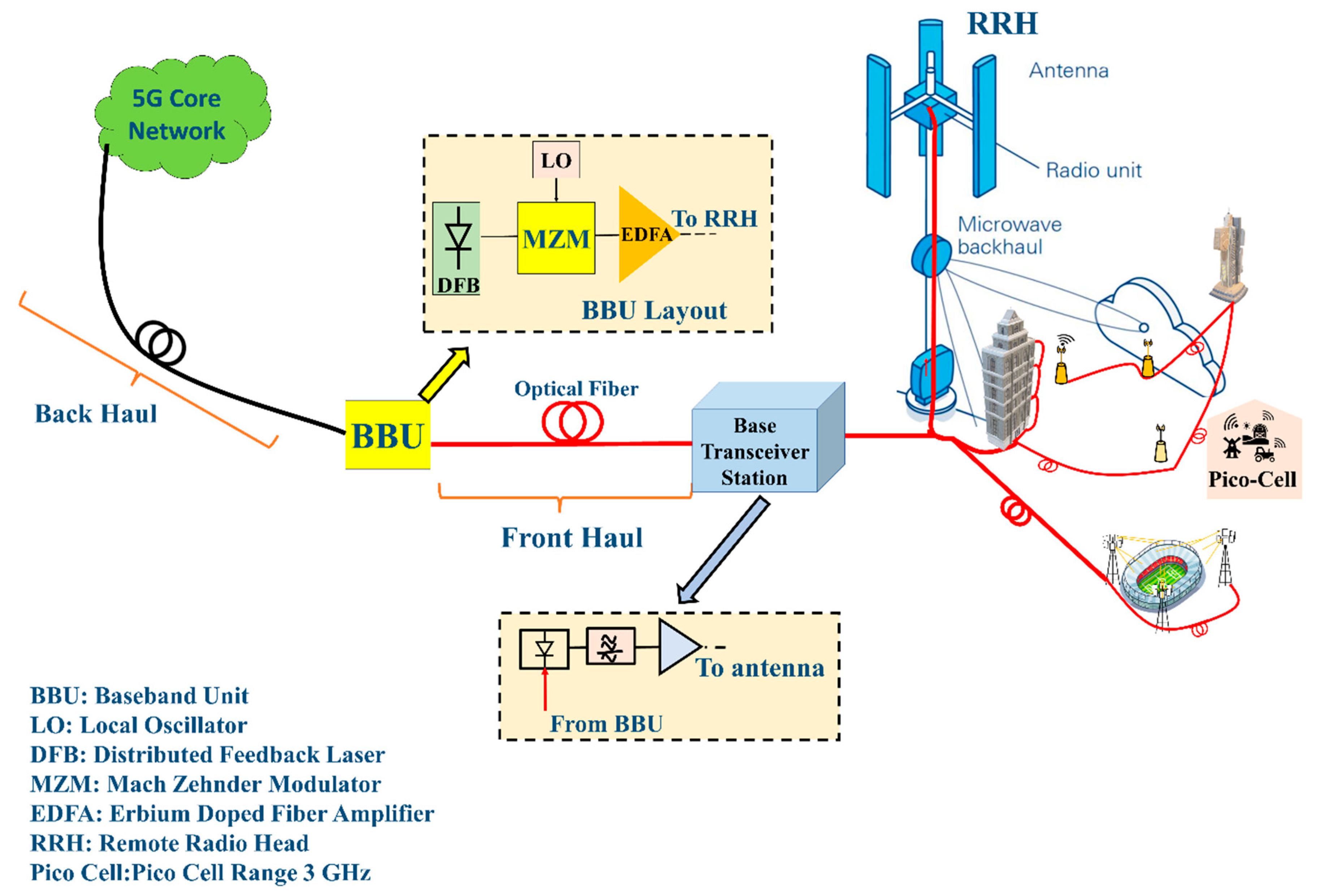
The fifth-generation (5G) of wireless networks aims to enhance the energy efficiency, end-to-end latency and capacity of networks. The radio access network has become more centralized as the number of base stations (BS) has increased exponentially [1]. Because it enhances scalability and decreases network maintenance, a centralized radio access network (C-RAN) reduces capital costs. A fronthaul (FH) connects baseband units (BBU) and distant radio heads in order to support a C-RAN. As shown in Figure 1, optical fronthaul (OFH) links, such as radio over fiber (RoF) links, constitute the mainstay in OFH. Due to its cost-effective and easy paradigm, which improves the network’s range, this transport approach is a significant option for high-capacity wireless transmission for transporting analogue or digital signals in OFH.
1.1. Motivation
This transport approach is a significant innovation for extremely high-capacity wireless transmission by virtue of a simple and cost-effective paradigm that extends the network’s reach [2,3]. Despite their benefits, such as minimal electromagnetic intrusions, lower loss rates and larger bandwidth, RoF links suffer from channel and linear distortions caused by system components, which can be rectified using linearization methods [4,5,6,7,8,9]. Analog radio over fibre (A-RoF) [1,2,3,4,5,6,7,8,9,10], digital radio over fibre (D-RoF) [11,12] and sigma delta radio over fibre (S-DRoF) [13,14,15,16,17] are all different types of RoF implementations.
A-RoF suffers from signal degradation and has a network expansion range of only a few tens of kilometres. The reach of the network for D-RoF is efficient for longer lengths [11], but due to the greater resolution bandwidth of the analogue digital converter (ADC) and the requirement of additional signal processing the system’s cost increases. In fronthaul networks, inadequate spectral efficiency and high demand for data traffic are also undesirable [12,17]. The Common Public Radio Interface (CPRI) bottleneck is bypassed in S-DRoF by employing sigma-delta modulation (SDM), which works as a 1-bit ADC. The high quantization noise is caused by a 1-bit operation, which necessitates the use of a bandpass filter on the receiver side, increasing the complexity of these systems. As a result, the A-RoF system is a better alternative than D-RoF and S-DRoF [18] since it is simple, inexpensive and already has a widespread infrastructure.
Because of the limitations imposed by the optical and microwave components, analogue fronthaul applications are limited. Many linearization methods have been proposed to address these issues [4,5,6,7,8,9], but these methodological solutions have been questioned due to limited bandwidth, high method complexity and the requirement of returning the output signal to the base station (feedback), which is a lengthy process [18].
The 5G network is expected to provide Gbit/s of connection, acting as a connector for total connectivity and coverage. Enhanced mobile broadband is one of the most widely utilised scenarios (eMBB). By utilizing revolutionary technological solutions, such as new radios (NR), 5G enables multi-services and a wide range of capabilities. Because it affects the coexistence with other systems, 5G NR enables the used multiplexing mechanism [19,20]. Multiple waveforms for multicarrier transmission have been proposed for 5G due to this coexistence capability (including 4G systems), including cyclic prefix-based orthogonal frequency division multiplexing (OFDM), filtered orthogonal frequency division multiplexing (F-OFDM) and generalised frequency division multiplexing (GFDM), which have been framed by the 3GPP for the 5G NR Release 15 that describes the eMBB scenario.
1.2. Problem Statement
In order to overcome the issues explained, the fibre–wireless (FiWi) technology based on RoF connections can be exploited to support 5G communications by jointly transporting all radio frequency (RF) signals and using the optical fibre features as an RF transport solution to accomplish the work items of 5G bands stated in 3GPP [21].
Multi-input multioutput (MIMO) is a conceivable method for most new mobile/wireless networks, which are pushed by today’s users’ high data rates. When compared to the performance of a single-input single-output (SISO) system, the MIMO approach is expected to improve transmission distance, data rate and reliability. As a result, it is a primary objective that the MIMO approach must be addressed when designing any FiWi system to enable wire free connection for next generation (NG) broadband networks.
1.3. Objectives
The experimental implementation of a 5G NR FiWi system employing an analogue optical transportation network built on RoF technology with a connection length of 10 km is shown in this study with the motivation to address wired and wireless link reach for the considered scenarios. Apart from this, a linearization technique is evaluated to enhance the performance. In eMBB situations, we implement 2 × 2 MIMO to increase the multiband 5G NR signal transmission range. As a proof of concept, the supercell scenario is accomplished at a 20 m distance using 3 GHz, while the femtocell scenario is realized at a distance of 20 m using the 20 GHz band. The following are the paper’s key contributions:
- Combination of a 2 × 2 MIMO and an RoF-based hybrid FiWi system, as well as testing with a 5G NR transceiver at 3 and 20 GHz to show the multiband propagation and extend the wired transmission range through a wireless link.
- In a supercell situation, convolutional neural network (CNN)-based digital pre-distortion (DPD) is used to improve the performance.
- In line with the C-RAN architecture, experimental assessment is made of multiband 5G NR transmissions using a 10 km analog FH.
2. Literature Review
The utilizaThe RoF systems integrated with the fibre–wireless approach are discussed in this section including linearization methods for the performance improvement in RoF networks. As seen in Table 1, the linearization of OFH has been a major study topic. The desire for greater linearization to obtain higher performance has switched attention to machine learning (ML). Because machine learning is such a novel area, a current literature evaluation has been conducted for all methodologies, with a focus on machine learning methods. Table 1 summarizes a comprehensive literature evaluation for the alleviation of RoF system deficits.
3. 5G New Radio Hybrid MIMO-Based Fibre–Wireless System
The proposed RoF system is integrated into the wireless system to obtain a hybrid fibre–wireless system. The proposed system has been explored utilising an eMBB scenario in this article. A supercell with a frequency of 3 GHz and an indoor femtocell with a frequency of 20 GHz are tested in this study.
The following are the four primary components of this experimental system:
- Generation of signal and its utilization in the system.
- Digital pre-distortion.
- Analog RoF-based OFH for the transmission of radio frequency (RF) signals.
- A fibre–wireless system with a total of 2 × 2 MIMO channels.
3.1. Signal Generation and Utilization
A Mach–Zehnder modulator (MZM) modulates a 1310 nm wavelength to drive a 1310 nm distributed feedback laser. The RF1 signal is applied to one of the MZM’s arms by the first vector signal generator (VSG1). At 20 GHz, RF1 is a 5G NR signal. The 3 GHz flexible waveforms’ (OFDM, GFDM, F-OFDM) signals from the 5G transceiver correspond to RF2. The biasing voltages VBIAS1 and VBIAS2 are chosen in such a way that the observed spectrum is free of the high peak to average power ratio and high-frequency peaks in the measured frequency selection.
3.2. CNN Based Digital Pre-Distortion
For VCSEL-based RoF connections [60] and DFB-based RoF links [53], DPD has been widely investigated. DPD is a useful tool for reducing nonlinearities in OFH connections. DPD has been proposed using a Volterra-based memory system and a generalised memory polynomial [1,2,60]. Machine learning approaches have recently been presented as a method for DPD. When compared to Volterra-based conventional designs, neural network-based DPD appears to yield a considerably greater reduction in signal impairments. As a result, this research employs deep neural network-based DPD. Both carrier frequencies are analysed using DPD In the following subsection, a detailed explanation of the working principle of the proposed CNN-based DPD is discussed.
3.2.1. Convolutional Neural Network (CNN)-Based DPD Method
Convolutional neural networks (CNN) cascades the RoF connection that develops a RoF NN model and train it to imitate the original RoF link because the output of an RoF connection is known. After we have created the appropriate CNN DPD model, we can backpropagate through this RoF CNN and tweak the parameters. The first layer of a CNN is the convolutional layer. It extracts features from input data and generates a feature map with the help of a kernel (convoluted data).
A convolutional operation consists of the kernel or filter (kernel matrix), input data (input matrix) and feature map. Assuming that the investigated RoF connection has the function and as an output signal and that a baseband signal must be sent over it, DPD attempts to compute the inverse transfer function of this RoF link, represented by , whose output is then denoted by .
This becomes
while
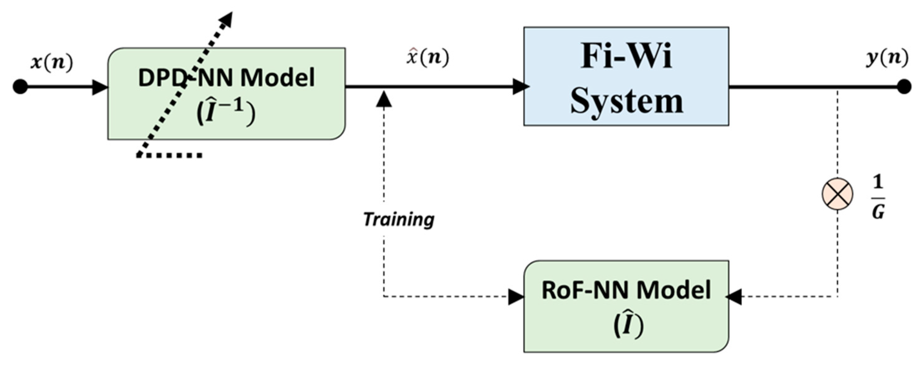
as G represents the gain. The CNN determines the used for pre-distortion in this case. Because the ideal is unknown, direct training for creating the CNN for DPD is not possible, as shown in Figure 2.
The second CNN first replicates the RoF link. For a generic RoF connection, is the input and is the output. As a result of this, the CNN can now determine an estimated transfer function I. Once the RoF CNN model is created, the model weights are set, and it is then coupled to the CNN DPD model. We now utilise the original input, , and output as training data to determine the error and then use a loss function. We then reverse promote it through to train .
3.2.2. Training Algorithm
The CNN DPD model training pseudocode is given below in Algorithm 1. Firstly, we train an emulated RoF CNN model that uses the input and output of the original RoF connection, and after this model training is achieved, we connect the CNN to the actual RoF link to this (post distorter) DPD block and commence the pre-distortion procedure when this training is completed (see Pseudocode 1). It is represented in the pseudocode that the CNN is established on with updates on that is performed on the pre-distortion block used by the terms of as shown in Figure 2.
| Algorithm 1: DPD Training with CNN |
| ← for i Z do ← : //FI-Wi Transmission ← Train on , //Fi-Wi Transmission CNN updates //Fixed NN weights of ← Train on . //() ← : //Pre-distort end for |
The loss evaluation function is mean square error (MSE), the optimization function is ADAM, the activation function is ReLu, and the values are monitored via backpropagation. Z number of iterations are carried out to enhance the performance.
3.3. Radio Frequency Transport Using Analog Optical Fronthaul
A 10 km single-mode fibre (SMF) transmits the optical signal. The signal is subsequently retrieved using a photodetector (PD). The PD sends the received electrical signal to the diplexer (DPX) The diplexed signal must be separated, which is performed through amplification. The signals are then transferred to a 5G transceiver and a vector signal analyzer (VSA) for post-processing and performance testing.
3.4. MIMO-Based FiWi System
After receiving the optical signal at the photodiode, it is then converted into an electrical domain signal followed by the duplex operation and is ready for reception on wireless channels. The duplexed signal is ready to be transmitted at the wireless channels after it is received at the photodiode. Because we have two bands of signals, MIMO with a dimension of 2 × 2 should suffice to capture the signal and assess the wireless link’s performance.
As a result, the FiWi system contains two RRHs, each with its transmitter. As a result, the RX1 and RX2 receivers receive signals and that are represented as
where is the first broadcast waveform and denotes the second, and denote the channel noise. With to , is the channel coefficient. Intersymbol interference (ISI) and optical fibre chromatic dispersion add to the MIMO system’s complexity. As a consequence, the frequency domain equalisation (FDE) technique is applied, resulting in MIMO complexity being reduced.
4. Experimental Setup
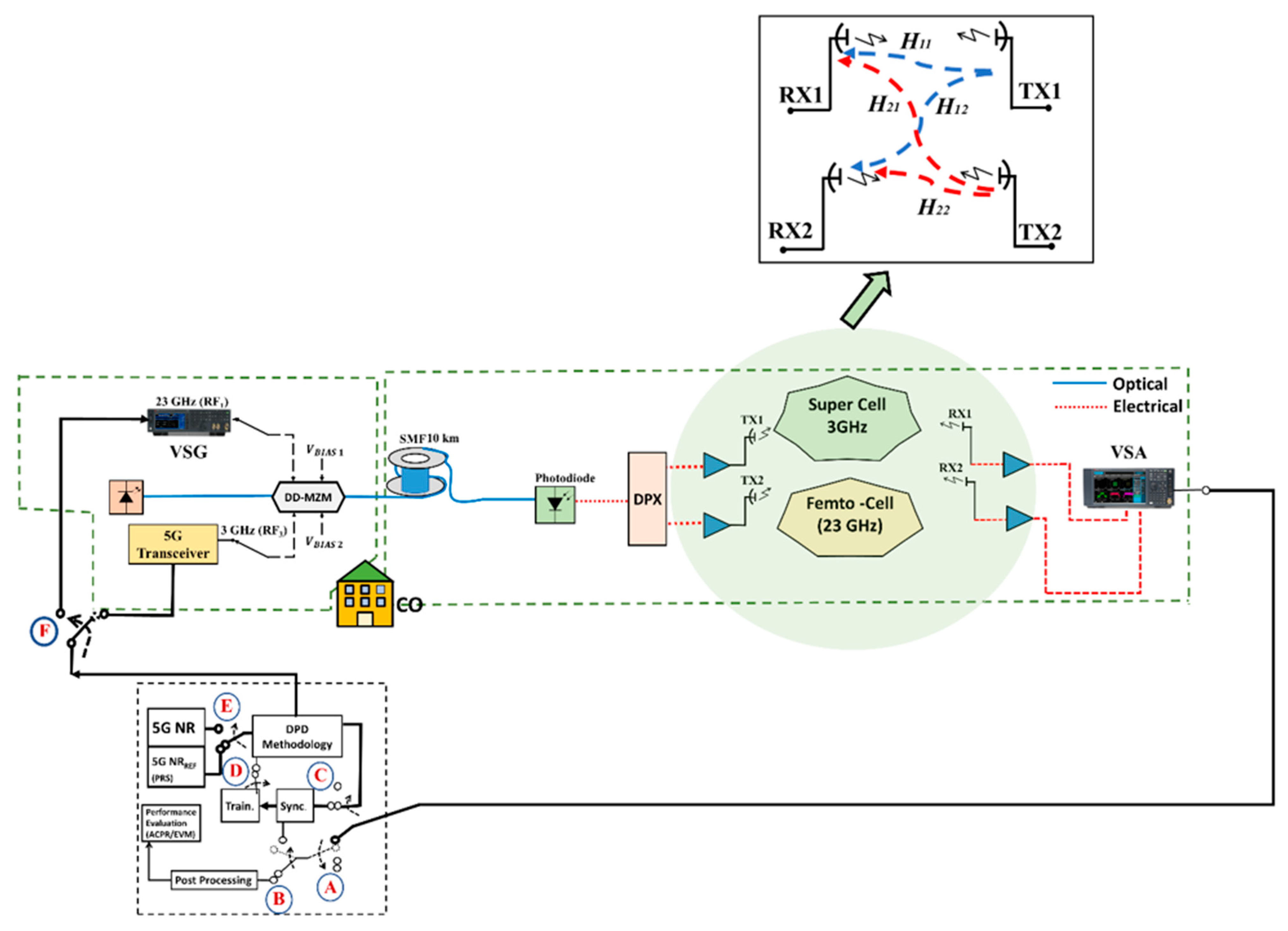
To validate the proposed FiWi 2 × 2 MIMO equipped with the CNN DPD technique, we employed a 5G NR scenario at 3 GHz and 20 GHz, both comprising of 50 MHz bandwidth as demonstrated in the previous work [23,24], but there was no integration of fibre–wireless, and also there was no DPD employed. The system represented in Figure 3 uses a dual drive Mach Zehnder modulator (MZM) with two distinct RF-driven signals and a 1310 nm DFB laser. The 5G transceiver transmits RF2, a 3 GHz flexible waveform signal, while the vector signal generator (VSG), labelled VSG, sends RF1, a 5G NR waveform at 20 GHz. The DPD procedure is divided into three steps.
Firstly, the up-converted signal at their respective carrier frequencies of 3 and 20 GHz passes over 10 km of standard single-mode fibre (SSMF) and is collected by a photodetector (0.69 A/W) that receives and converts the signal back to the electrical domain. Because the multiband must be separated individually, an amplification phase is implemented. A diplexer (DPX) separates the 3 GHz and 20 GHz frequencies. The signals are then passed via a series of vector signal analyzers (VSA). Each VSA output is sent to the post-processing block to be evaluated for performance. This phase is carried out without the use of DPD, which implies that the output is assessed without the use of DPD.
In the second phase, referred to as the DPD training phase, the DPD technique depicted in Figure 3 is applied, and training is performed until the error converges.
To put it another way, DPD backs up the idea underlying inverting the amplitude and phase responses recorded at the EA electrical amplifiers. Depending on the user’s wants and comparative criteria, CNN approaches can be employed.
To achieve synchronization for the received waveforms, we employ the positioning reference signal (PRS) provided in the 5G NR framework (both input and output). The bandwidth of PRS is expected to be 20 MHz/106 resource blocks. The received and output reference broadcast signals are coupled in the time domain, and the power delay profile (PDP) is evaluated via threshold block to establish the first path of arrival [61].
The pre-distorted baseband signals are supplied into the DPD block in the third phase, where VSGs upconvert them to their carrier frequency before being fed into the optical link. Before being forwarded to the DPD training phase, the signal generated at the photodiode is passed via a diplexer DPX to isolate the different multibands. During the DPD validation stage, we flip the switches in the other manner. Pre-distortion and then transmitting the frames to the VSG complete the evaluation for 5G NR frames. We find that real-time operation in the adaptation is unnecessary since the nonlinearities of the RoF connection slowly change owing to thermal effects and component ageing. Table 2 lists the parameters used, which have previously been discussed in [1,2] and other state of the art [18] studies.
Table 3 shows the CNN settings that result in optimised NN performance. The parameters that constitute the design of the planned convolutional neural network are listed in Table 3. A trial and error test is used to pick the parameters [18]. The table’s last part computes the NN’s expressions in terms of its coefficients to determine its complexity.
5. Experimental Results
The experimental findings of the tests deployed as described in the preceding section are explained. One way of measuring the accuracy of coefficient estimates for various designs is the mean square error (MSE). The MSE is 27 dB when no DPD is employed, whereas CNN reduces it to 20 dB.
The suggested method is compared and the magnitude of the errors is presented in the form of error vector magnitude (EVM). We utilise GMP techniques as a baseline architecture to compare with our recent work [18].
Error Vector Magnitude
The standardized performance metric in 3GPP is the error vector magnitude (EVM), which gives the optimum constellation location for each received symbol. The EVM value of the device is the root mean square (RMS) of all error vector magnitudes between the received symbol positions and their nearest ideal constellation sites.
where gives constellation symbols, represents the constellation’s real symbol associated with the symbol “” and denotes the real symbol linked with . 3GPP has set the EVM standard limit for the 256 QAM modulation rate to be 3.5% [62,63].
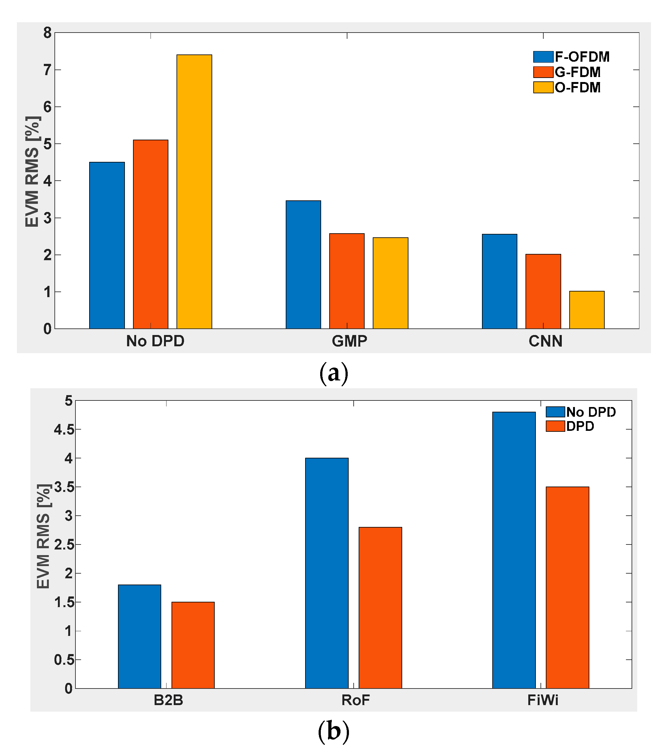
The EVM is displayed in Figure 4a for flexible waveforms without DPD, with the GMP DPD method followed by the CNN DPD method. For all flexible waveform designs, it is notable that the CNN DPD approach achieves a better reduction than GMP.
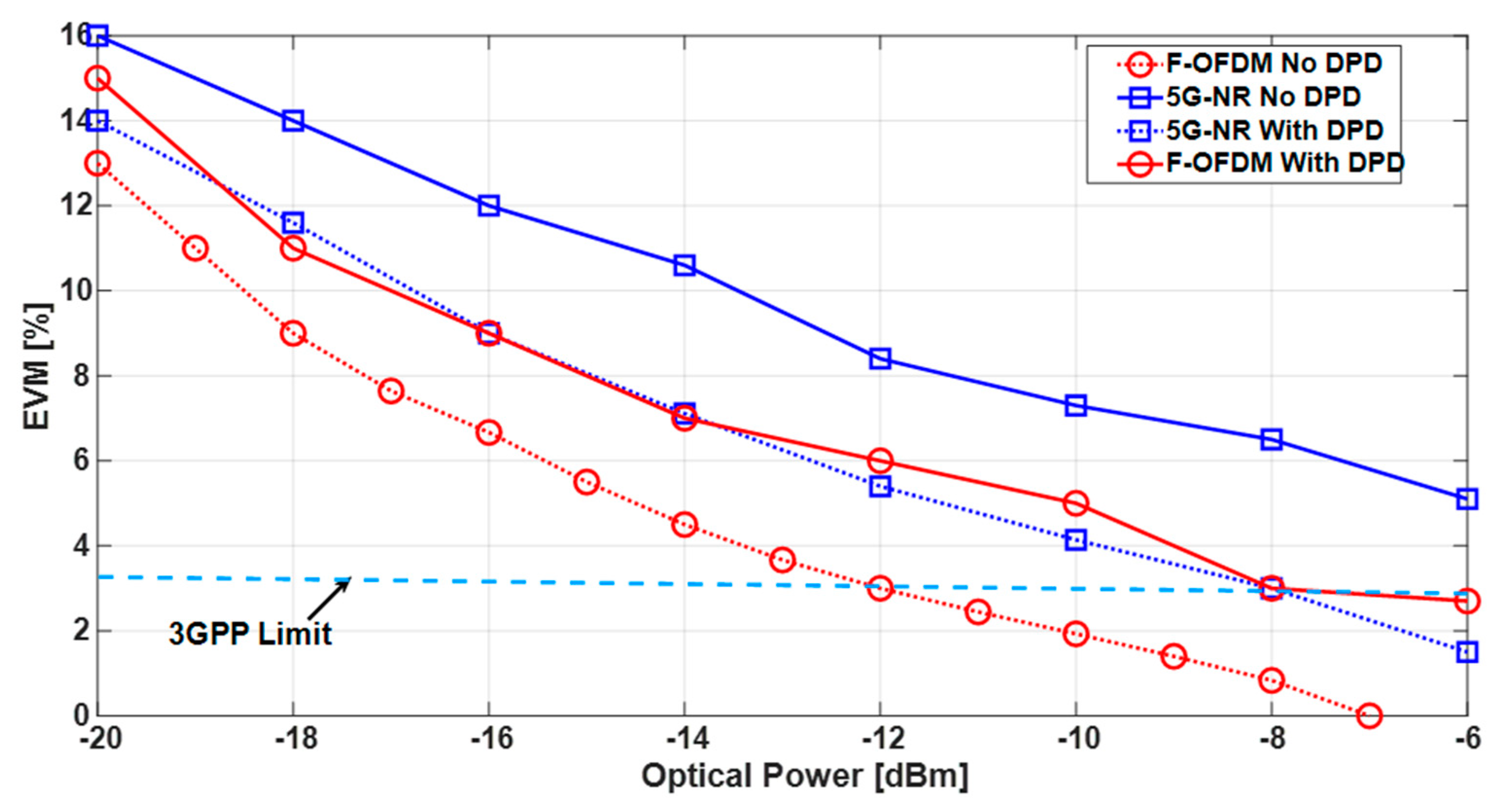
In Figure 4b, we compare a case called back-to-back (B2B) where a laser and a photodiode are connected via a patch cord of less than 1 m SMF. It can be seen that B2B has 2% EVM, which signifies that this is the least EVM obtained if we remove the presence of fibre or wireless integration into the system. Similarly, we have added the results of a generic RoF case from our previous study [18] and compared it with the proposed hybrid FiWi link. It is noticeable that the hybrid FiWi system has a 5% EVM. The performance of the system is further enhanced using CNN-based DPD, bringing the EVM value to 3.5% Additionally, we show EVM results for the received optical power for the F-OFDM and 5G NR waveforms in Figure 5. The received optical power for the 5G NR waveform is not meeting the 3GPP criteria, which means that the dynamic range is affected. Therefore, it becomes fundamentally important to improve the performance via DPD. DPD ensures that EVM is within the limits from −8 to −6 dBm. If we consider the F-OFDM waveform, the dynamic range in the 3GPP limit is 2 dB, whereas F-OFDM with DPD has extended the dynamic range to 7 dB from −12 dBm to −6 dBm within 3GPP limits.
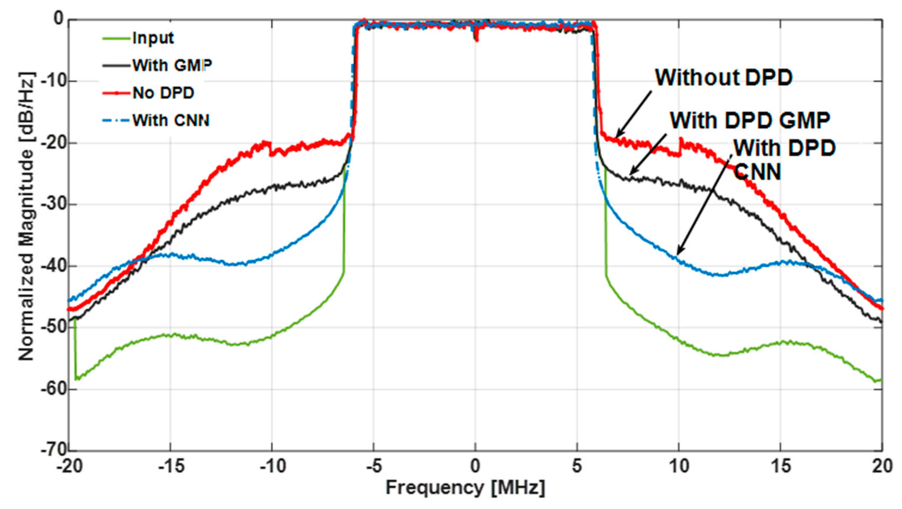
In addition to EVM, the performance is also measured in terms of power spectral density (PSD). The PSD measures the ratio of power in the useful band to the power in the adjacent bands. It is also known as adjacent channel leakage or power ratio (ACLR/ACPR). The trends in Figure 6 show that the PSD for a case without DPD has a −25 dBc value. The 3GPP has set these limits to be −35 dBc. To improve the performance, DPD with GMP and CNN is utilized and it is signified that CNN improvement is better than GMP, which has been discussed in [18].
In Table 4, the EVM and PSD at 0 dBm are expressed for the DPD utilized.
6. Conclusions
This article validates an unprecedented DPD controlled 5G-NR-based hybrid fibre–wireless system equipped with 2 × 2 MIMO. A 10 km SMF is used to send a 5G NR signal at a distant radio head targeting an eMBB scenario with a femtocell (3 GHz) and a supercell (20 GHz) for eMBB applications. The hybrid fibre–wireless system via the proposed CNN-based DPD achieves a significant performance that meets the 3GPP specifications. The proposed CNN DPD approach reduces EVM to 3.2% and PSD to −41 dBc. The integration of fibre–wireless has great potential, and the experimental results suggest that this can be a potential solution for the transport and access network of future communication networks. Future work includes the optimization of fibre–wireless infrastructure and improvement in the linearization methodologies for better performance.
Author Contributions
Conceptualization, M.U.H.; A.A.C.; A.R. and S.K.O.S.; methodology, M.U.H.; software, M.U.H. and J.S.; validation, M.U.H. and S.K.O.S.; formal analysis, M.U.H.; J.S. and A.R.; investigation, M.U.H.; J.S. and S.K.O.S.; resources, M.U.H. and J.S.; data curation, writing—original draft preparation, M.U.H.; A.A.C.; A.R. and S.K.O.S.; supervision, M.U.H. All authors have read and agreed to the published version of the manuscript.
Funding
This research received no external funding.
Institutional Review Board Statement
Not applicable.
Informed Consent Statement
Not applicable for studies not involving humans.
Data Availability Statement
The data presented in this study are available on request from the corresponding author.
Conflicts of Interest
The authors declare no conflict of interest.
References
- Hadi, M.; Awais, M.; Raza, M.; Khurshid, K.; Jung, H. Neural Network DPD for Aggrandizing SM-VCSEL-SSMF-Based Radio over Fibre Link Performance. Photonics 2021, 8, 19. [Google Scholar] [CrossRef]
- Hadi, M.U.; Awais, M.; Raza, M.; Ashraf, M.I.; Song, J. Experimental Demonstration and Performance Enhancement of 5G NR Multiband Radio over Fibre System Using Optimized Digital Predistortion. Appl. Sci. 2021, 11, 11624. [Google Scholar] [CrossRef]
- Nanni, J.; Polleux, J.-L.; Algani, C.; Rusticelli, S.; Perini, F.; Tartarini, G. VCSEL-Based radio-over-G652 fibre system for short-/medium-range MFH solutions. J. Lightwave Technol. 2018, 36, 4430–4437. [Google Scholar] [CrossRef]
- Zhang, X.; Zhu, R.; Shen, D.; Liu, T. Linearization Technologies for Broadband Radio-Over-Fibre Transmission Systems. Photonics 2014, 1, 455–472. [Google Scholar] [CrossRef]
- Nanni, J.; Baschieri, L.; Hadi, M.U.; Polleux, J.-L.; Tartarini, G. Effective Digital Pre-Distortion Loop for Front Hauls based on short-λ-VCSELs over pre-existent G-652 Infrastructures. In Proceedings of the 2021 International Topical Meeting on Microwave Photonics (MWP), Pisa, Italy, 15–17 November 2021; pp. 1–4. [Google Scholar] [CrossRef]
- Vieira, L.; Gomes, N.J.; Nkansah, A.; van Dijk, F. Behavioral modeling of radio-overfibre links using memory polynomials. In Proceedings of the 2010 IEEE Topical Meeting on Microwave Photonics (MWP), Montreal, QC, Canada, 5–9 October 2010; pp. 85–88. [Google Scholar]
- Hekkala, A.; Hiivala, M.; Lasanen, M.; Perttu, J.; Vieira, L.C.; Gomes, N.J.; Nkansah, A. Predistortion of Radio Over Fibre Links: Algorithms, Implementation, and Measurements. IEEE Trans. Circuits Syst. I Regul. Pap. 2011, 59, 664–672. [Google Scholar] [CrossRef]
- Fuochi, F.; Hadi, M.U.; Nanni, J.; Traverso, P.A.; Tartarini, G. Digital predistortion technique for the compensation of nonlinear effects in radio over fibre links. In Proceedings of the 2016 IEEE 2nd International Forum on Research and Technologies for Society and Industry Leveraging a Better Tomorrow (RTSI), Bologna, Italy, 7–9 September 2016; pp. 1–6. [Google Scholar]
- Vieira, L.C.; Gomes, N.J.; Nkansah, A. An experimental study on digital predistortion for radio-over-fibre links. In Proceedings of the Asia Communications and Photonics Conference and Exhibition, Shanghai, China, 8–12 December 2010; pp. 126–127. [Google Scholar] [CrossRef]
- Nanni, J.; Giovannini, A.; Hadi, M.U.; Lenzi, E.; Rusticelli, S.; Wayth, R.; Perini, F.; Monari, J.; Tartarini, G. Controlling Rayleigh-Backscattering-Induced Distortion in Radio Over Fibre Systems for Radioastronomic Applications. J. Lightwave Technol. 2020, 38, 5393–5405. [Google Scholar] [CrossRef]
- Hadi, M.U.; Jung, H.; Ghaffar, S.; Traverso, P.A.; Tartarini, G. Optimized digital radio over fibre system for medium range communication. Opt. Commun. 2019, 443, 177–185. [Google Scholar] [CrossRef]
- Nirmalathas, A.; Gamage, P.A.; Lim, C.; Novak, D.; Waterhouse, R. Digitized Radio-Over-Fiber Technologies for Converged Optical Wireless Access Network. J. Lightwave Technol. 2010, 28, 2366–2375. [Google Scholar] [CrossRef]
- Wang, J.; Jia, Z.; Campos, L.A.; Knittle, C.; Jia, S. Delta-Sigma Modulation for Next Generation Fronthaul Interface. J. Lightwave Technol. 2018, 37, 2838–2850. [Google Scholar] [CrossRef]
- Van Kerrebrouck, J.; Breyne, L.; Li, H.; Bauwelinck, J.; Torfs, G.; Demeester, P.; Bohn, T. Real-Time All-Digital Radioover-Fibre LTE Transmission. In Proceedings of the 2017 Advances in Wireless and Optical Communications (RTUWO), Riga, Latvia, 2–3 November 2017; pp. 83–86. [Google Scholar]
- Li, H.; Bauwelinck, J.; Demeester, P.; Torfs, G.; Verplaetse, M.; Verbist, J.; Van Kerrebrouck, J.; Breyne, L.; Wu, C.-Y.; Bogaert, L.; et al. Real-Time 100-GS/s Sigma-Delta Modulator for All-Digital Radio-Over-Fibre Transmission. J. Lightwave Technol. 2020, 38, 386–393. [Google Scholar] [CrossRef] [Green Version]
- Li, H.; Hajipour, J.; Attar, A.; Leung, V.C.M. Efficient HetNet implementation using broadband wireless access with fibre-connected massively distributed antennas architecture. IEEE Wirel. Commun. 2011, 18, 72–78. [Google Scholar] [CrossRef]
- Hadi, M.; Jung, H.; Traverso, P.; Tartarini, G. Experimental evaluation of real-time sigma-delta radio over fiber system for fronthaul applications. Int. J. Microw. Wirel. Technol. 2021, 13, 756–765. [Google Scholar] [CrossRef]
- Hadi, M.U. Practical Demonstration of 5G NR Transport Over-Fiber System with Convolutional Neural Network. Telecom 2022, 3, 103–117. [Google Scholar] [CrossRef]
- Hadi, M.U.; Awais, M.; Raza, M. Multiband 5G NR-over-Fiber System Using Analog Front Haul. In Proceedings of the 2020 International Topical Meeting on Microwave Photonics (MWP), Matsue, Japan, 24–26 November 2020; pp. 136–139. [Google Scholar] [CrossRef]
- Pereira, L.A.M.; Lima, E.S.; Cerqueira, S.A. A Multi-band 5G-NR Fiber-wireless System for Next-generation Networks. In Proceedings of the 2021 SBMO/IEEE MTT-S International Microwave and Optoelectronics Conference (IMOC), Fortaleza, Brazil, 24–27 October 2021; pp. 1–3. [Google Scholar] [CrossRef]
- LTE. Evolved Universal Terrestrial Radio Access (E-UTRA); ETSI, TS 136 104 V8.2.0; Base Station (BS) Radio Transmission and Reception; European Telecommunications Standards Institute: Valbonne, France, 2018. [Google Scholar]
- Zeng, H.; Liu, X.; Megeed, S.; Shen, A.; Effenberger, F. Digital Signal Processing for High-Speed Fiber-Wireless Convergence [Invited]. J. Opt. Commun. Netw. 2019, 11, A11–A19. [Google Scholar] [CrossRef]
- MHadi, U.; Ghaffar, S.; Murtaza, G. 5G NR MIMO Enabled MultiBand Fiber Wireless System using Analog Optical Front Haul. In Proceedings of the 2020 IEEE 17th International Conference on Smart Communities: Improving Quality of Life Using ICT, IoT and AI (HONET), Charlotte, NC, USA, 14–16 December 2020; pp. 59–62. [Google Scholar] [CrossRef]
- Hadi, M.U.; Basit, A.; Khurshid, K. MIMO Enabled MultiBand 5G NR FibreWireless using Sigma Delta over FibreTechnology. In Proceedings of the 2021 International Bhurban Conference on Applied Sciences and Technologies (IBCAST), Islamabad, Pakistan, 12–16 January 2021; pp. 1007–1010. [Google Scholar] [CrossRef]
- Zhu, R.; Zhang, X. Linearization of Radio-Over-Fibre Systems by Using Two Lasers with Different Wavelengths. In Proceedings of the 2014 IEEE MTT-S International Microwave Symposium (IMS), Tampa, FL, USA, 1–6 June 2014. [Google Scholar]
- Huang, Y.; Chen, Y.; Yu, J. Nonlinearity mitigation of RoF signal using machine learning based classifier. In Proceedings of the Asia Communications and Photonics Conference, Guangzhou, China, 10–13 November 2017; p. Su2A.28. [Google Scholar]
- Li, D.; Yu, S.; Jiang, T.; Han, Y.; Gu, W. An M-ary SVM-based detection for 16-QAM RoF system with data-dependent cross modulation distortion. In Proceedings of the Asia Communications and Photonics Conference, Hong Kong, China, 19–23 November 2015; p. ASu3J.4. [Google Scholar]
- Gonzalez, N.G.; Zibar, D.; Caballero, A.; Monroy, I.T. Experimental 2.5-Gb/s QPSK WDM Phase-Modulated Radio-Over-Fibre Link with Digital Demodulation by a KK-Means Algorithm. IEEE Photonics Technol. Lett. 2010, 22, 335–337. [Google Scholar] [CrossRef]
- Fernandez, E.A.; Torres, J.J.G.; Soto, A.M.C.; Gonzalez, N.G. Radio-over-fibre signal demodulation in the presence of non-Gaussian distortions based on subregion constellation processing. Opt. Fibre Technol. 2019, 53, 102062. [Google Scholar] [CrossRef]
- Liu, S.; Wang, X.; Zhang, W.; Shen, G.; Tian, H. An Adaptive Activated ANN Equalizer Applied in Millimeter-Wave RoF Transmission System. IEEE Photonics Technol. Lett. 2017, 29, 1935–1938. [Google Scholar] [CrossRef]
- Liu, S.; Xu, M.; Wang, J.; Lu, F.; Zhang, W.; Tian, H.; Chang, G.-K. A Multilevel Artificial Neural Network Nonlinear Equalizer for Millimeter-Wave Mobile Fronthaul Systems. J. Lightwave Technol. 2017, 35, 4406–4417. [Google Scholar] [CrossRef]
- Liu, S.; Alfadhli, Y.M.; Shen, S.; Tian, H.; Chang, G.K. Mitigation of multi-user access impairments in 5G A-RoF-based mobile-fronthaul utilizing machine learning for an artificial neural network nonlinear equalizer. In Proceedings of the Optical Fibre Communication Conference, San Diego, CA, USA, 11–15 March 2018. [Google Scholar]
- Liu, E.; Yu, Z.; Yin, C.; Xu, K. Nonlinear distortions compensation based on artificial neural networks in wideband and multi-carrier systems. IEEE J. Quantum Electron. 2019, 55, 800305. [Google Scholar] [CrossRef]
- Liu, J.; Zou, X.; Bai, W. Performance enhancement of UFMC based radio over fibre system using ANN equalizer. In Proceedings of the Asia Communications and Photonics Conference, Hangzhou, China, 26–29 October 2018. [Google Scholar]
- Hadi, M.U.; Mittal, I. On the Use of SVR based Machine Learning Method for Nonlinearities Mitigation in Short Range Fronthaul Links. In Proceedings of the 2021 10th IEEE International Conference on Communication Systems and Network Technologies (CSNT), Bhopal, India, 18–19 June 2021; pp. 628–631. [Google Scholar]
- Hadi, M.U.; Basit, A. Machine Learning for Performance Enhancement in Fronthaul Links for IOT Applications. In Proceedings of the 2021 International Conference on Digital Futures and Transformative Technologies (ICoDT2), Islamabad, Pakistan, 20–21 May 2021; pp. 1–5. [Google Scholar]
- Lee, J.; He, J.; Wang, Y.; Fang, C.; Wang, K. Experimental demonstration of millimeter-wave radio-over-fibre system with convolutional neural network and binary convolutional neural network (BCNN). arXiv 2020, arXiv:2001.02018. Available online: https://arxiv.org/abs/2001.02018 (accessed on 5 December 2021).
- Lee, J.; He, J.; Wang, K. Neural networks and FPGA hardware accelerators for millimeter-wave radio-over-fibre systems. In Proceedings of the International Conference on Transparent Optical Networks, Bari, Italy, 19–23 July 2020; p. Mo.D1.5. [Google Scholar]
- Safari, L.; Baghersalimi, G.; Karami, A.; Kiani, A. On the Equalization of an OFDM-Based Radio-over-Fibre System Using Neural Networks. Radioengineering 2017, 26, 162–169. [Google Scholar] [CrossRef]
- Zhou, Q.; Lu, F.; Xu, M.; Peng, P.-C.; Liu, S.; Shen, S.; Zhang, R.; Yao, S.; Finkelstein, J.; Chang, G.-K. Enhanced Multi-Level Signal Recovery in Mobile Fronthaul Network Using DNN Decoder. IEEE Photonics Technol. Lett. 2018, 30, 1511–1514. [Google Scholar] [CrossRef]
- Xu, T.; Shevchenko, A.N.; Zhang, Y.; Jin, C.; Zhao, J.; Liu, T. Information rates in Kerr non-linearity limited optical fibre communication systems. Opt. Express 2021, 29, 17428–17439. [Google Scholar] [CrossRef] [PubMed]
- Draa, M.N.; Hastings, A.S.; Williams, K.J. Comparison of photodiode nonlinearity measurement systems. Opt. Express 2011, 19, 12635–12645. [Google Scholar] [CrossRef] [PubMed]
- Chen, Z.; Yan, L.; Pan, W.; Luo, B.; Zou, X.; Guo, Y.; Jiang, H.; Zhou, T. SFDR enhancement in analog photonic links by simultaneous compensation for dispersion and nonlinearity. OSA Opt. Expr. 2013, 21, 20999–21009. [Google Scholar] [CrossRef]
- Roselli, L.; Borgioni, V.; Zepparelli, F.; Ambrosi, F.; Comez, M.; Faccin, P.; Casini, A. Analog laser predistortion for multiservice radio-over-fibre systems. J. Lightwave Technol. 2003, 21, 1211–1223. [Google Scholar] [CrossRef] [Green Version]
- Hekkala, A.; Lasanen, M.; Vieira, L.C.; Gomes, N.J.; Nkansah, A. Architectures for Joint Compensation of RoF and PA with Nonideal Feedback. In Proceedings of the 2010 IEEE 71st Vehicular Technology Conference, Taipei, Taiwan, 16–19 May 2010; pp. 1–5. [Google Scholar]
- Mateo, C.; Carro, P.L.; Garcia-Ducar, P.; De Mingo, J.; Salinas, I. Experimental evaluation of the feedback loop effects in digital predistortion of a radio-over-fibre system. In Proceedings of the 2017 Ninth International Conference on Ubiquitous and Future Networks (ICUFN), Milan, Italy, 4–7 July 2017; pp. 1039–1041. [Google Scholar]
- Mateo, C.; Clemente, J.; Garcia-Ducar, P.; Carro, P.L.; de Mingo, J.; Salinas, I. Digital predistortion of a full-duplex Radio-over-Fibre mobile fronthaul link with feedback loop. In Proceedings of the 2017 13th International Wireless Communications and Mobile Computing Conference (IWCMC), Valencia, Spain, 26–30 June 2017; pp. 1425–1430. [Google Scholar]
- Mateo, C.; Carro, P.L.; García-Dúcar, P.; De Mingo, J.; Salinas, Í. Minimization of Feedback Loop Distortions in Digital Predistortion of a Radio-Over-Fibre System with Optimization Algorithms. IEEE Photonics J. 2017, 9, 7904414. [Google Scholar] [CrossRef]
- He, J.; Lee, J.; Kandeepan, S.; Wang, K. Machine Learning Techniques in Radio-over-Fibre Systems and Networks. Photonics 2020, 7, 105. [Google Scholar] [CrossRef]
- Hraimel, B.; Zhang, X. Low-cost broadband predistortion-linearized single drive x-cut Mach-Zehnder modulator for radio-over-fiber systems. Photonics Technol. Lett. 2012, 24, 1571–1573. [Google Scholar] [CrossRef]
- Hadi, M.U.; Nanni, J.; Polleux, J.-L.; Traverso, P.A.; Tartarini, G. Direct digital predistortion technique for the compensation of laser chirp and fiber dispersion in long haul radio over fiber links. Opt. Quant Electron. 2019, 51, 205. [Google Scholar] [CrossRef]
- Hadi, M.U.; Nanni, J.; Venard, O.; Baudoin, G.; Polleux, J.L.; Tartarini, G. Practically feasible closed-loop Digital Predistortion for VCSEL-MMF-based Radio-over-Fiber links. Radioengineering Czech Slovak Tech. Univ. 2020, 29, 37–43. [Google Scholar] [CrossRef]
- Hadi, M.U.; Kantana, C.; Traverso, P.A.; Tartarini, G.; Venard, O.; Baudoin, G.; Polleux, J. Assessment of digital predistortion methods for DFB-SSMF radio-over-fiber links linearization. Microw. Opt. Technol. Lett. 2020, 62, 540–546. [Google Scholar] [CrossRef]
- Cui, Y.; Zhang, M.; Wang, D.; Liu, S.; Li, Z.; Chang, G.K. Bit-Based support vector machine nonlinear detector for millimeter-wave radio-over-fibre mobile fronthaul systems. Opt. Express 2017, 25, 26186–26197. [Google Scholar] [CrossRef] [PubMed]
- Haas, B.M.; Murphy, T. A Simple, Linearized, Phase-Modulated Analog Optical Transmission System. IEEE Photonics Technol. Lett. 2007, 19, 729–731. [Google Scholar] [CrossRef]
- Ghannouchi, F.; Younes, M.; Rawat, M. Distortion and impairments mitigation and compensation of single- and multi-band wireless transmitters. IET Microw. Antennas Propag. 2013, 7, 518–534. [Google Scholar] [CrossRef]
- Duan, R.; Xu, K.; Dai, J.; Cui, Y.; Wu, J.; Li, Y.; Dai, Y.; Li, J. Linearity improvement based on digital signal processing in intensity-modulated analog optical links incorporating photonic frequency down conversion. In Proceedings of the Optical Fibre Communication Conference and Exposition, Los Angeles, CA, USA, 6–8 March 2012. [Google Scholar]
- Pei, Y.; Xu, K.; Li, J.; Zhang, A.; Dai, Y.; Ji, Y.; Lin, J. Complexity-reduced digital predistortion for subcarrier multiplexed radio over fibre systems transmitting sparse multi-band RF signals. Opt. Express 2013, 21, 3708–3714. [Google Scholar] [CrossRef]
- Wang, D.; Zhang, M.; Fu, M.; Cai, Z.; Li, Z.; Han, H.; Cui, Y.; Luo, B. Nonlinearity mitigation using a machine learning detector based on k-nearest neighbors. IEEE Photonics Technol. Lett. 2016, 28, 2102–2105. [Google Scholar] [CrossRef]
- Hadi, M.U.; Traverso, P.A.; Tartarini, G.; Venard, O.; Baudoin, G.; Polleux, J.-L. Digital Predistortion for Linearity Improvement of VCSEL-SSMF-Based Radio-Over-Fiber Links. IEEE Microw. Wirel. Compon. Lett. 2019, 29, 155–157. [Google Scholar] [CrossRef]
- Hadi, M.U.; Jacobsen, T.; Abreu, R.; Kolding, T. 5G Time Synchronization: Performance Analysis and Enhancements for Multipath Scenarios. In Proceedings of the 2021 IEEE Latin-American Conference on Communications (LATINCOM), Santo Domingo, Dominican Republic, 17–19 November 2021; pp. 1–5. [Google Scholar] [CrossRef]
- Mufutau, A.O.; Guiomar, F.P.; Fernandes, M.A.; Lorences-Riesgo, A.; Oliveira, A.; Monteiro, P.P. Demonstration of a hybrid optical fiber–wireless 5G fronthaul coexisting with end-to-end 4G networks. J. Opt. Commun. Netw. 2020, 12, 72–78. [Google Scholar] [CrossRef]
- Jiang, D.; Liu, G. An Overview of 5G Requirements. In 5G Mobile Communications; Xiang, W., Zheng, K., Shen, X., Eds.; Springer: Cham, Switzerland, 2017; pp. 3–26. [Google Scholar]
Figure 1.
Block diagram explaining backhaul connection to the baseband unit (BBU) connected to optical front haul (OFH), and then its transmission from the transceiver station. The base station further connects it to the remote radio heads (RRHs). Extending the network coverage via fibre and wireless infrastructure is shown w.r.t application scenarios such as picocell, stadiums, buildings, etc.

Figure 2.
Block schematic of the RoF system, which includes a DPD system based on CNN. The RoF NN model is produced by transmitting I/P and O/P through a RoF connection. Then, to train I, we backpropagate error through . By cascading the DPD-RoF model to an RoF connection, the model is linearized. DPD is performed in the digital baseband, hence no DACs or ADCs are required. Algorithm 1 displays the relationship between how CNN is created and taught.

Figure 3.
5G NR fibre–wireless system experimental block schematic. The functions are as follows: A: Selection switch for DPD or direct post-processing for performance evaluation; B: switch selection for synchronisation block or a performance post-processing block. C: B is turned towards synch and connected to train block, while C will be used to synch the DPD trained version. D: Training follows the synchronisation block. DPD: The training is enabled/disabled by DPD. E: The method of time synchronisation (TS) is necessary so that Tx and Rx waveforms are in tight synchronization. F: Required for checking DPD inputs before transmitting to VSGs. CNN has been picked for DPD training.

Figure 4.
Comparison of EVM for 5G NR and F-OFDM waveforms: (a) with GMP, CNN and without DPD for 0 dBm RF input power, while (b) with DPD and No DPD for B2B, RoF and FiWi.
Figure 4.
Comparison of EVM for 5G NR and F-OFDM waveforms: (a) with GMP, CNN and without DPD for 0 dBm RF input power, while (b) with DPD and No DPD for B2B, RoF and FiWi.

Figure 5.
EVM performance comparison for 5G NR and F OFDM waveforms with and without DPD for the received optical power.
Figure 5.
EVM performance comparison for 5G NR and F OFDM waveforms with and without DPD for the received optical power.

Figure 6.
PSD performance comparison with and without DPD.


Table 1.
State of the art for fibre–wireless RoF-based system and nonlinearity mitigation methods employed. The table abbreviates the nonlinearity mitigation approaches used (Opt = Optical, ML = Machine Learning, ACLR = Adjacent Channel Leakage Ratio, Dig = Digital, Elec = Electrical, ACLR = Adjacent Channel Leakage Ratio, EVM = Error Vector Magnitude, Elec = Electrical, Opt = Optical, EVM = Error Vector Magnitude ML = Machine Learning, Dig = Digital are used to abbreviate in the table).
| No. | Work Item | Method | Technique | Parameter | Linearization | Advantages | Disadvantages |
|---|---|---|---|---|---|---|---|
| 1 | Hadi et al. [19] | Analog RoF | MIMO-A-RoF | EVM, ACLR | No Linearization | Fibre–Wireless Novel Trial | Limited Performance |
| 2 | Pereira et al. [20] | Analog RoF | Fibre–Wireless | EVM | No Linearization | 10 m FiWi trial | Limited to 64 QAM |
| 3 | A. O. Mufutau et al. [21] | Hybrid optical | Fibre–Wireless | EVM | No Linearization | Coexistence trial | Limited to 64 QAM |
| 4 | Zeng et al. [22] | Fibre–Wireless Convergence | Fibre–Wireless Convergence | Relative Power Spectral Density | No Linearization | 25 Gbauds throughput | DSP Kit challenges with post-processing |
| 5 | Hadi et al. [23] | Analog RoF | MIMO-A-RoF | EVM, ACLR | No Linearization | Supercell case included with standardized | Limited Performance |
| 6 | Hadi et al. [24] | Sigma Delta RoF | MIMO-Sigma Delta RoF | EVM | No Linearization | Sigma Delta RoF amalgamation | Robust but limited distance due to high BPF quantization noise |
| 7 | Zhu et al. [25] | Opt | Dual wavelength linearization (DWL) | Second/third order nonlinear distortion | Complete RoF system | Suppression of second and third order nonlinearities | Transmission is wavelength dependent, i.e., nonlinear components are suppressed exclusively at anti-phased wavelengths. |
| 8 | Lam et al. [26] | Dig | Digital Post Distortion | ACLR, BER | RoF | All order nonlinear distortion components significantly compressed. | Digitizer with high speed is required. Uplinks are the only ones that apply. |
| 9 | Li et al. [27] | SVM | ML DPD | EVM | Fibre nonlinearity | 1.5 dB improvement | High data training and complexity |
| 10 | Gonzalez et al. [28] | ML | AI DPD | BER, OSNR | Cross Modulation Detection | N/A | N/A |
| 11 | Fernandez et al. [29] | ML | ML DPD | OSNR | Phase Modulation Impairments | 1.4 dB improvement | N/A |
| 12 | Liu et al. [30,31,32,33,34] | ML | ML DPD | EVM, ACLR | Laser Chirp | 10 dBs improvement | Limited to small link lengths |
| 13 | Hadi et al. [35,36,37,38,39] | Dig | ML-NN-based DPD | EVM | Laser | Learns nonlinearities | Limited to LTE framework. |
| 14 | Xu et al., Zhou et al. [40,41] | Dig | DNN DPD | ACLR, EVM | Black Box approach | N/A | Limited to 20 MHz bandwidth and 256 QAM modulation |
| 15 | Draa et al.; Chen et al. [42,43] | Elec | Analog DPD | IMD3 | Complete RoF system (Laser, photodiode, LNA) | IMD3 for phase maintenance | It suppresses second order nonlinear distortion for large bandwidth. |
| 16 | Roselli et al. [44] | Electrical | Analog DPD | IMD3 | RoF | Fixed phase for IMD3 components | |
| 17 | Hadi et al. [8] | Dig | Direct DPD | C/HD2, IIP2, IIP3 | Combination of fibre dispersion and laser chirp | Linearizes links up to tens of km | Because each RoF transmitter requires a particular pre-distorter, large-scale production is difficult. |
| 18 | Vieira et al. [9] | Dig | Conventional DPD | EVM | Laser | OFDM signal utilization | I/P tones must be sinusoidal (single/dual). |
| 19 | Hekkala et al. [45] | Dig | Conventional DPD | ACLR, BER | Laser | OFDM signal with 12.5 MHz bandwidth | The RoF link isn’t generic; it includes a 10 dB attenuation. |
| 20 | Carlos et al. [46] | Dig | Conventional DPD | EVM, ACLR | RoF | LTE 20 MHz signal | Only the magnitude (AM/AM) linearization is shown. |
| 21 | Carlos et al. [47] | Dig | Conventional DPD | NMSE, ACLR | RoF | LTE 20 MHz with 16 QAM modulation | Feedback is unrealistic. |
| 22 | Carlos et al. [48] | Dig | Conventional DPD | ACLR, EVM | RoF | Ideal and no feedback | The distributed feedback (DFB) laser was not pushed to higher RF I/P powers to evaluate the pre-distorter’s efficacy. |
| 23 | Hekkala et al. [41] | Dig | Conventional DPD | ACLR, EVM | Laser only | Less complexity and fewer overheads | The findings are attenuation dependent, which means that with the right attenuation and different optimization procedures, outcomes that are close to the ideal situation can be achieved. |
| 24 | He et al. [49] | Electrical | Conventional DPD | IMD3 | RoF | Fixed correction | Slight Improvement |
| 25 | Hraimel et al. [50] | Electrical | Conventional DPD | IMD3 | RoF | Phase maintenance is easy | Only Phase depended nonlinearities solved |
| 26 | MU. Hadi et al. [51] | Dig | Direct DPD | ACLR, IMD | RoF | Only requires transient chirp coefficient, no exhaustive training. | High complexity as a baseband signal needs to be oversampled by a very large over factor. |
| 27 | MU. Hadi et al. [52] | Dig | DPD | ACLR | RoF | Feasible closed loop DPD | Shown only for VCSEL |
| 28 | MU. Hadi et al. [53] | Dig | DPD | ACLR, EVM | RoF | DVR, GMP, MP | N/A |
| 29 | Cui et al. [54] | SVM | Deep Learning | BER | Modulation Impairments | 1.3 dB improvement | Small improvement |
| 30 | Hass et al. [55] | Opt | Mixed Polarization | Second/third order nonlinear distortion | Complete RoF system | Nonlinearities of second and third order are suppressed. | DPD deployment at the RRH level, further complicating the RRH. |
| 31 | Ghannouchi et al. [56] | Dig | DPD | Third order nonlinearities | Power Amplifier | Wideband enhancements are feasible. | The DSP necessary is difficult. |
| 32 | Duan et al. [57] | Dig | DPD | ACLR, EVM | Laser | More precision with fewer DSP requirements | Enormous energy consumption |
| 33 | Pei et al. [58] | Dig | DPD | ACLR | Modulator | ACLR suppression increased by 15 decibels. | Complex feedback. |
| 34 | Wang et al. [59] | KNN | ML | BER | Fibre nonlinearity | Improvement of 0.6 decibels | Large training data required |
Table 2.
Link Parameters.
| Parameters | Values |
|---|---|
| Signal Types | = 3, 20 GHz F/O/G—FDM waveform Modulation Data Rate = 256 QAM |
| Laser Diode | = 1310 nm Dual Drive Mach Zehnder Modulator |
| Fibre | |
| Photoreceiver | = 0.69 A/W |
Table 3.
CNN architecture values.
| Framework | Parameters |
|---|---|
| Optimizer | ADAM |
| Activation function | ReLu |
| Type of output layer | Softmax |
| Loss type | Mean Square Error (MSE) |
| Hidden Layers N | 20 |
| Neurons per layer K | 15 |
| Regularization Type | L1 |
| Regularization factor | 0.01 |
| Learning rate Batch size | 0.01 16, 32, 64, 128, 256 |
| Validation split | 0.3 |
| Training specimens | 500,000 |
| Testing specimens | 200,000 |
| Complexity | |
| (4 + N) K + (N − 1) K2 + 6 | 5986 |
Table 4.
Synopsis of the results for E.V.M and PSD as performance metric.
| Methodology | EVM (%) | PSD (dBc) |
|---|---|---|
| No-DPD RoF | 7 | −27 |
| GMP-DPD RoF | 2 | −30 |
| CNN DPD RoF | 1.1 | −39 |
| No-DPD FiWi | 6 | −21 |
| GMP-DPD FiWi | 5 | −30 |
| CNN DPD FiWi | 3.2 | −41 |
Publisher’s Note: MDPI stays neutral with regard to jurisdictional claims in published maps and institutional affiliations. |
© 2022 by the authors. Licensee MDPI, Basel, Switzerland. This article is an open access article distributed under the terms and conditions of the Creative Commons Attribution (CC BY) license (https://creativecommons.org/licenses/by/4.0/).
Share and Cite
MDPI and ACS Style
Hadi, M.U.; Song, J.; Soman, S.K.O.; Rahimian, A.; Cheema, A.A. Experimental Evaluation of Hybrid Fibre–Wireless System for 5G Networks. Telecom 2022, 3, 218-233. https://0-doi-org.brum.beds.ac.uk/10.3390/telecom3020014
AMA Style
Hadi MU, Song J, Soman SKO, Rahimian A, Cheema AA. Experimental Evaluation of Hybrid Fibre–Wireless System for 5G Networks. Telecom. 2022; 3(2):218-233. https://0-doi-org.brum.beds.ac.uk/10.3390/telecom3020014
Chicago/Turabian StyleHadi, Muhammad Usman, Jian Song, Sunish Kumar Orappanpara Soman, Ardavan Rahimian, and Adnan Ahmad Cheema. 2022. "Experimental Evaluation of Hybrid Fibre–Wireless System for 5G Networks" Telecom 3, no. 2: 218-233. https://0-doi-org.brum.beds.ac.uk/10.3390/telecom3020014