1. Introduction
Autonomous vehicles (AVs) have the potential to not only revolutionise the way we interact with our cars but also those of other road users and the surrounding infrastructure [
1]. While the technological aspects of AVs such as perception, planning, control, and coordination are often the focus of research [
2,
3,
4,
5], the importance of user acceptance should not be understated [
6]. In particular how members of the public perceive AVs [
7] and in turn form trust of their behaviours will be key in driving their adoption [
8,
9,
10,
11].
The VENTURER project was funded by the UK government, as one of its first Innovate UK funded Connected Autonomous Vehicle projects and was conducted predominantly in the South Gloucestershire and Bristol areas of the UK. It systematically assessed the responses of passengers and other road users, including pedestrians and cyclists, to Autonomous Vehicles, in a series of increasingly complex trials and demonstrations in urban settings. The trials and the data collected provided a greater understanding of how AV technology performs, how people interact with that technology, its acceptance by the public, and has helped to inform the development of potential insurance models and legal frameworks for AVs. Developing this understanding contributed to the first key steps towards facilitating the deployment of AVs on UK roads. Here we provide an evaluation of the technology development during the VENTURER project, the ways in which that technology was used for the purposes above, and the most important lessons that were learned from both a summary of the technical aspects, and a more general review of how to set up and operate a large consortium-based project that spans across research institutions and advanced industry. VENTURER was a three-year project that completed in the Summer of 2018, but various constraints prevented us from publishing some of this article’s contents until now.
This article is laid out as follows. First, we briefly describe the project’s key outputs and trial activities. Next we introduce the members of the VENTURER project and their role in the work discussed below. We then introduce the Wildcat vehicle and describe some of the key aspects of the overall architecture. A high level overview is then given of the Decision Making System (DMS), the sensing capabilities and the Wireless communication systems. This is followed by a brief, predominantly awareness raising, focus on selected technology developments associated with the vehicles that were used in the trials. We also include an overview of the objectives of those trials, in order to introduce some informative challenges that we overcame, and lessons learned from doing so. Finally, we conclude with recommendations for others who may decide to travel the path to building and then using a Connected Autonomous Vehicle test bed facility for investigating both technological developments and human factors aspects together and simultaneously in an integrated experimental context.
Key Outputs of the VENTURER Project
Over the course of the trials and testing activities the project has amassed an extensive data set. This includes all of the backup sensor data collected by the Wildcat vehicle (the Landrover Wildcat provided by our project partner BAE systems), including data streams from vehicle control systems (accelerator, braking, steering commands) and GPS data. The desired trajectories of the decision making systems are also captured, along with the state of the DMS at all times allowing traceability of any decisions made. Additionally, sensor data was created by Fusion Processing Ltd., and the Wildcat’s Velodyne LIDAR, on-board cameras and radar data was stored. This is an invaluable amount of data which can be used by research students and other interested parties, to study, develop and test new algorithms, techniques and capabilities. In turn, it forms part of the VENTURER project legacy and is available on request.
2. The Venturer Trials
The project was structured around three main experimental trials and a technology demonstration. These were focused on investigating specific facets of the interactions and human factors aspects of human users, interactants or observers of the AV technology in action, and thereby we conducted social research to develop insight into public acceptance challenges associated with CAV technology. Additionally, these trials were augmented at appropriate times with more publicly oriented demonstrations of the project achievements. The trials are outlined as follows:
Trial 1—Control Handover between manual and autonomous operation: In trial 1 participants experienced several instances of handover of steering, accelerator and braking control between the Autonomous Control System of the Wildcat and the participant during a multi-circuit drive around the UWE Frenchay campus roadways.
Trial 2—Operation and Response at Junctions with other vehicles: Trial 2 involved assessing the experiences and reactions of participants during interactions between the vehicles in the trial, with subjects of study being people both in the Wildcat and around it in other manually driven vehicles.
Trial 3—Autonomous Vehicle Interactions with Cyclists and Pedestrians: In trial 3, similar assessments were carried out, but for the cases of the Wildcat interacting with different road users, exemplified by pedestrians and cyclists.
Technology Demonstration—Wireless Communication Between a Bus and Wildcat: This was devised in order to illustrate the wireless communications capabilities developed in VENTURER.
Importantly, a key requirement of this project was to combine the use of a high-fidelity simulation suite to both provide cross-validation and be an environment for facilitation of the testing of scenarios which might be unsafe in the real world trials. In fact, all participants who took part in any of the three trials experienced it both in a real vehicle and also in this immersive simulator that recreated, as far as was possible within the constraints of a simulated environment, a very similar overall experience. An output of VENTURER shows that participant trust levels remained fairly consistent between manoeuvres carried out in the simulator and in the wildcat [
12].
It is clear that simulation will play a significant role in the introduction and continuing implementation of this technology, so comparisons between participants’ experiences in each of the two environments were an important aspect of each trial. For this reason, every participant who took place in any of the trials described, experienced that trial in a real-world setting and in the simulator. However, in this article we focus primarily on the real-world developments that took place in VENTURER.
3. Project Partners
A major part of the VENTURER Project relied on integrating several different experimental technologies, developed by several project partners, into a cohesive system. The technology integration was led by the Bristol Robotics Laboratory (BRL), with other critical technology collaborators, developing and implementing essential advanced technology aspects of the overall architecture. The following is a list of these project partners:
The Bristol Robotics Laboratory—The BRL is a close collaboration between the University of Bristol (UoB) and the University of the West of England (UWE). The technology integration was led by the BRL which was closely aligned with the development of the Decision-Making System (DMS).
BAE Systems—Providing the main test vehicle, including low-level piloting-control, localisation and some sensing and perception capabilities.
Fusion Processing—bespoke sensor suite to provide more complex sensing and perception.
UWE Centre for Transport and Society—Investigating factors of acceptability of driverless vehicles with society.
Williams Advanced Engineering—Designed and led the implementation of the immersive vehicle simulator facility.
AXA Insurance—Investigations into the technology’s disruptive effects in the vehicle insurance landscape.
Burges-Salmon—Investigations into the technology’s disruptive effects in the vehicle legal landscape.
Atkins Global Ltd.—Provided essential programme management skills and expertise to ensure effective collaboration. Atkins further provided trial development, planning and co-ordination as well as intelligent mobility expertise.
It should be noted also that important contributory activities came from wireless communications experts from UoB’s world-renowned Communication Systems and Networks group. The combined expertise of the project partners allowed VENTURER to take a holistic approach and ensured that relevant core research areas of autonomous mobility had been covered. Using the end-goal of completing the three main
Trials, outlined in
Section 2, and working backwards we outlined a set of technological requirements necessary to ensure suitability for the inclusion of public participants.
The VENTURER trials were focused on enabling a large number of participants, made up of the public, to experience a range of typical driving scenarios and record their responses. The participants were selected so as to be representative of a broad range of persona types, age categories and experience in driving, so as to ensure meaningful results. For scientific validity this required a high degree of repeatability at both an individual participant level and across the set of all participants. This was enabled by the use of several experimental technologies, and was one of the most challenging aspects of this project. A large part of the partner collaboration activity was undertaken so as to prepare and integrate the advanced sensors that fuse stereo video and penetrating radar data to achieve perception of surrounding objects with the autonomous vehicle’s lower-level Pilot control systems and Decision-Making.
4. The Wildcat Vehicle
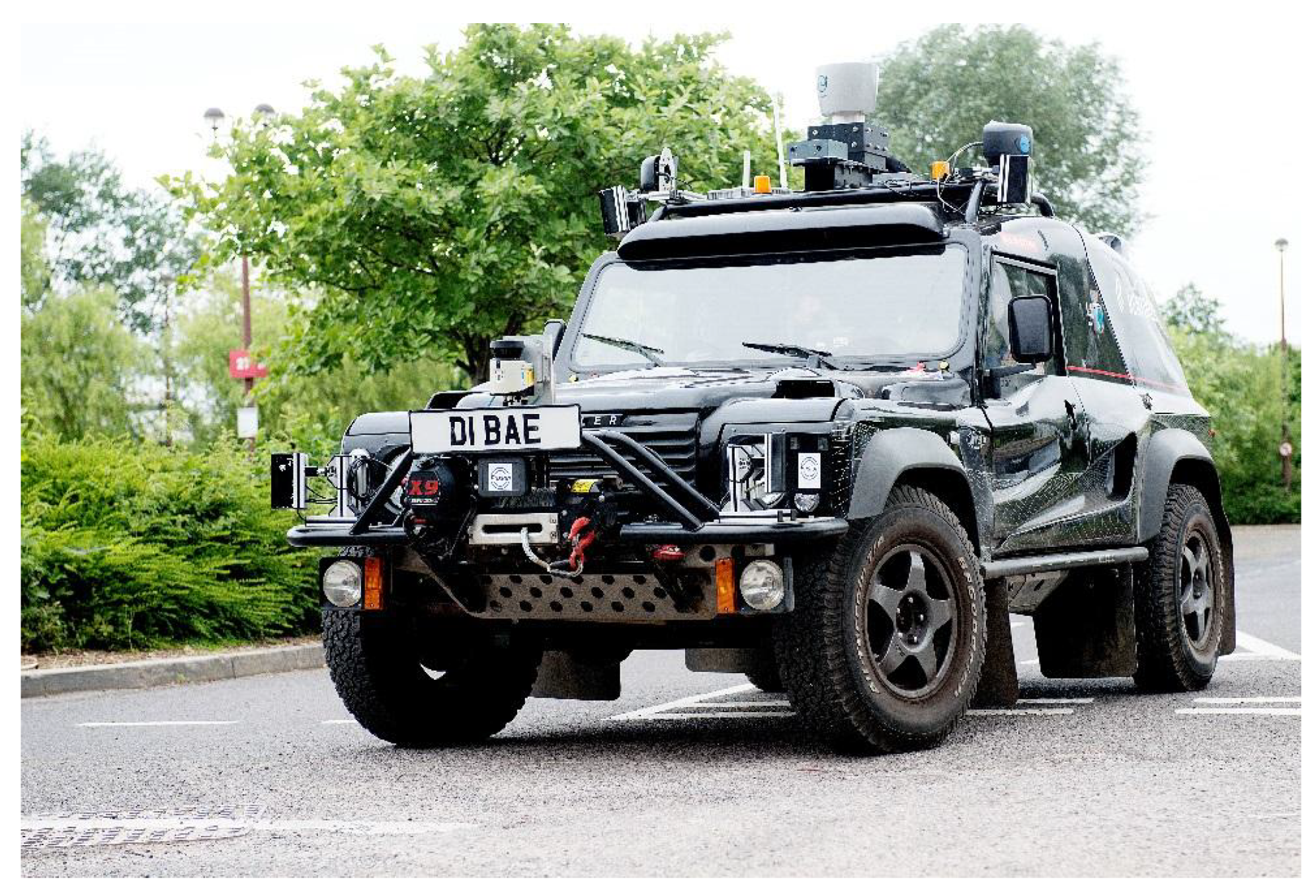
We selected a variety of vehicles and equipped them with those aspects of the technology made available via the project that were appropriate for the experimental scenarios envisaged. We then undertook specific experiments to demonstrate the wide applicability of the developed capabilities. The main experimental vehicle was the Wildcat shown in
Figure 1, developed and provided by BAE Systems. Additionally, a Renault Twizy and a Westfield POD were converted to operate autonomously. A FirstBus Service Vehicle, while remaining manually driven, was adapted specifically to provide direct wireless connectivity to other vehicles. However, the focus of this article is on the technologies required to create the sense, plan and act framework developed for the Wildcat.
The Wildcat’s low-level controller, referred to as the pilot, was tasked with interpreting a given trajectory that was supplied from the higher-level Decision Making System, so as to create steering and acceleration command values which in turn led to actuating the steering wheel, throttle and brakes respectively.
The vehicle itself is Left Hand Drive (LHD), meaning that all the ‘normal’ driver inputs are located on the left and the right hand side is a passenger seat. This allowed some participants to experience being sat on the traditional driver’s side for UK cars, while the safety driver had access to all the manual driving functions if required.
The trials included participants inside and outside of the vehicle. The trials evaluated the participants’ trust via feedback provided by them during and after each trial for a range of scenarios, including interactions between the AV and pedestrians on pavements, as well as between the AV and pedestrians crossing the road at pedestrian crossings and other locations. Participants would observe interactions with the passive environment and other staged interactions using actors.
One example investigated a controlled handover between the AV and participating human driver. In addition to assessing the Wildcat’s ability to continue operating correctly and smoothly, we also assessed the adequacy of interactions with other road users (including the driver) during this process.
As mentioned above, from the outset the system was divided into two main hierarchical components. At the high-level, is the Decision-Making System (DMS); similar to the actions of the conscious mind of a human driver, i.e., the part of the overall system that decides on driving strategy, high-level navigation and desired trajectories on the road. Then at the low-level is the Pilot, making control choices to effectively execute our desired high-level goals; similar to our fine motor skills, adjusting pressure on the throttle and turning the steering wheel. This aims to follow a human driver analogy that when driving, you may decide which exit to take from a roundabout and therefore plan which lane to be in to be able to achieve that decision but, as an experienced driver, you will leave the details of your body’s actions in making fine adjustments in the feedback control so as to stay in a lane or traverse between them while adhering to some sensible speed profile, to your subconscious mind. In this paper, we will not focus on the lower-level pilot controller, but rather on the DMS.
5. Decision Making System Development
The DMS used to control the behaviours of the Wildcat was developed by researchers and academic staff from Bristol Robotics Laboratory who were employees of the University of Bristol.
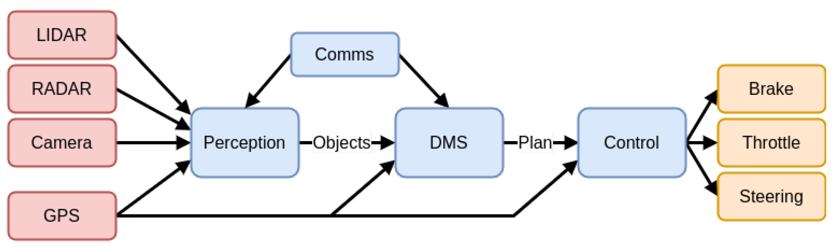
Figure 2 shows the overall architecture of the automated driving system and the information flows between the component subsystems. The red
Sensor blocks denote sensor data input (LIDAR, RADAR, Camera and GPS) which feed into the blue
Decision blocks (Perception, DMS, Control), the
Comms box provides communication between Perception and the DMS, while the
Control block outputs the actuation commands (Brake, Throttle and Steering) for the vehicle. It is noteworthy that although the DMS predominantly uses perceptions of the environment determined by the ‘Fusion Processing Ltd’ signal processing block that receives most of the raw sensor data, it is necessary for the DMS to receive some direct sensor data. Also note that the block labelled ‘Control’ is the pilot control referred to above, which was developed and supplied by BAE Systems.
The Robot Operating System (ROS) is a flexible framework for writing robot software. It is a collection of tools, libraries, and conventions that aim to simplify the task of creating complex and robust robot behaviour across a wide variety of robotic platforms. Here, the Robot Operating System (ROS) provided a documented and flexible framework for integrating multiple components, both within the parts of the DMS and between the DMS and the lower-level systems, and was threrefore adopted as the standard for implementing and interfacing with the DMS. Since both the vehicle simulator and the Wildcat implemented identical ROS interfaces, the same DMS software was employed in both contexts.
5.1. Optimisation-Based Approaches for Driving
A key feature of the adopted approach was the use of speed-based separation. Although a fixed physical separation between the apparent boundaries of the AV and others vehicles around it was kept constant, as speed increased a vehicle’s apparent horizontal dimensions would increase proportionally. This approach provides a simple way of capturing uncertainty, which is greater at higher speed due to the fixed reaction times of the driving system. Consequently, a ’bunching’ effect is seen when speed is reduced, for example, in a narrow stretch of road. To achieve cooperative behaviour, the AV considers and evaluates options for the other cars according to its own estimate of their objectives [
13]. The result is that it behaves considerately, waiting at junctions and holding back before turning in, in case another car is about to turn across its path. The relative weights given to other vehicles is thought of as the key to adjusting the car’s ‘personality’, with high self-weight resulting in behaviour that could be considered to be more aggressive (gap forcing) and low self-weight, with respect to objectives of other vehicles, resulting in behaviour that could be considered to be more passive (gap waiting). Further results on this control approach were published in [
14].
The initial investigations into these optimisation approaches showed promising performance and sensible behaviour in a range of driving situations. However they both suffered from latency challenges, despite efforts to implement them using the fastest tools available (IPOPT [
15] for nonlinear and Gurobi [
16] for integer optimization). While most trajectories could be calculated in fractions of a second, this was not guaranteed and this variability in response time means that creating reliable plans consistently difficult and therefore from a practical level it wasn’t suited for participant trials. If instead we looked at model-based approaches, these naturally depend on both accurate and timely information on both the positions and velocities of other vehicles, requiring tracking as well as detection components. These would demand additional effort within VENTURER and so unfortunately were not viable.
5.2. Fixed-Path Planning with Speed Trajectories
In order to ensure a reasonably high degree of reliability and repeatability the scope of the decision making evolved towards a fixed-route planner. The role of this planner is to load from a database a pre-defined spatial path (in this case the lane centre-line), over a spatial horizon (e.g., 50 m), and produce an accompanying optimal speed trajectory to follow. This trajectory was calculated using jerk-bounded S-curves, often used in robotics [
17], to produce smooth, comfortable vehicle motions for the passengers.
For the majority of the driving situations, following the centre-line, adjusting the vehicles velocity and ensuring to stop at junctions and turnings is all that is required. However, in order to overtake a parked vehicle the planner instead produces ‘lane change’ trajectories to switch between lanes. This simply takes the centre-line of the oncoming lane and uses bézier curves [
18] to produce smooth transitions between the two. Thus, the vehicle will change lane from left-to-right, continue until it has safely passed the obstructing vehicle, then change lane back from right-to-left. The planner has preset limits on important physical factors such as maximum angular velocity to ensure that corners, as well as overtaking manoeuvres, are taken at comfortable speeds, slowing down when necessary.
5.3. Decision-Making Engine for Driving Scenarios
The initial DMS (used up to Trial 2) employed a Finite State Machine [
19] (FSM) as its core engine for decision-making, but in the later parts of the VENTURER trials, the decision-making engine was re-implemented using a behaviour tree, since these are known to encapsulate all the functionality of FSMs, but in a more modular and adaptable fashion [
20]. They have been extensively used for AI characters in computer games and were proposed for Unmanned Air Vehicle (UAV) autonomy. Behaviour trees were implemented in the ROS [
21] environment using the
py_trees_ros package incorporating the
py_trees Python library, providing full behaviour tree functionality with a built-in ROS interface.
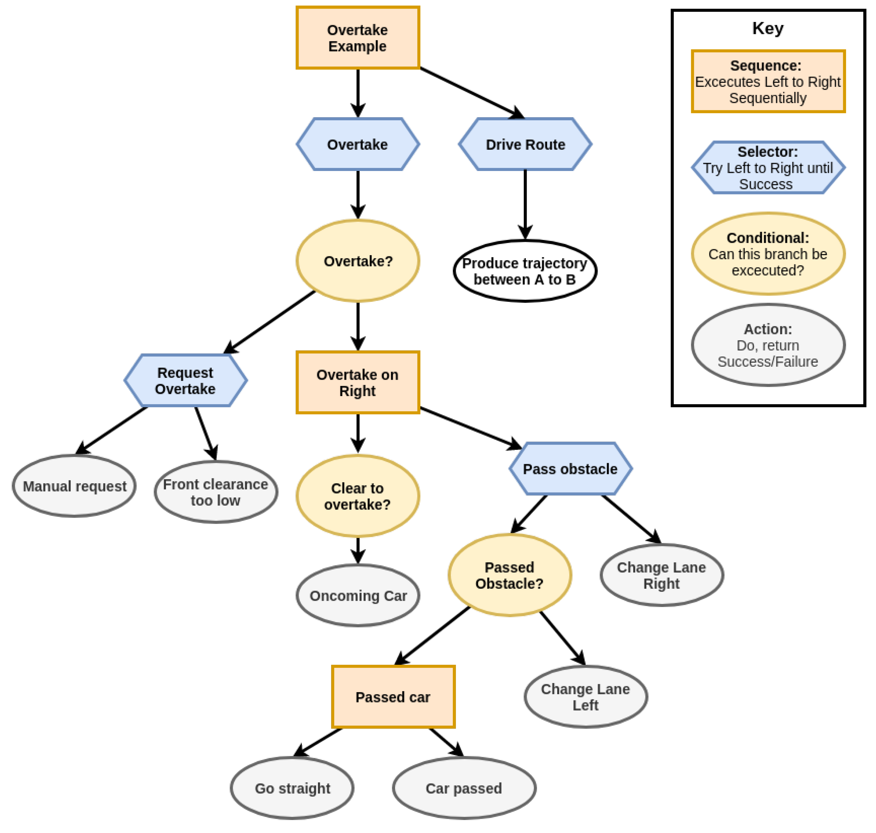
Figure 3 shows a section of the tree designed to drive between a start point A and stopping point B with a potential overtake manoeuvre. The right hand side of the tree continuously requests and returns trajectories for the next part of the route from the trajectory planner (in this case our centre line planner). The left hand side of the tree is triggered only if an overtake manoeuvre is required. In this particular lap there is a parked car in the way and so once the ‘front clearance too low’ condition is activated an overtake is requested. To carry this out we must wait until we are ‘clear to overtake?’. Then a change from left-to-right lane trajectory is requested and once the parked vehicle was successfully passed, a right-to-left lane trajectory is requested. Once this has been completed we move back to the right hand side of the tree and continue on getting trajectories until we reach point B.
The close correspondence of the behaviour tree with the pre-defined trial script is central to being able to quickly go from experiment design to reliably and repeatably testing. Additionally, this provided a suitable modular framework for rapid prototyping and testing different sensor information and logic for ensuring conditions such as ‘clear to overtake?’ are observed and acted upon accordingly. For example, during the bus-based wireless communications demonstration described in
Section 7 below, the Trial 2 overtaking behavioQQur tree illustrated in
Figure 3 is reused but, the condition of ‘clear to overtake?’ can be additionally initiated by the V2V communication sensor on board the bus if it can perceive from its own unobscured sensors that the Wildcat’s overtake manoeuvre is clear to be executed.
5.4. Integration and Implementation
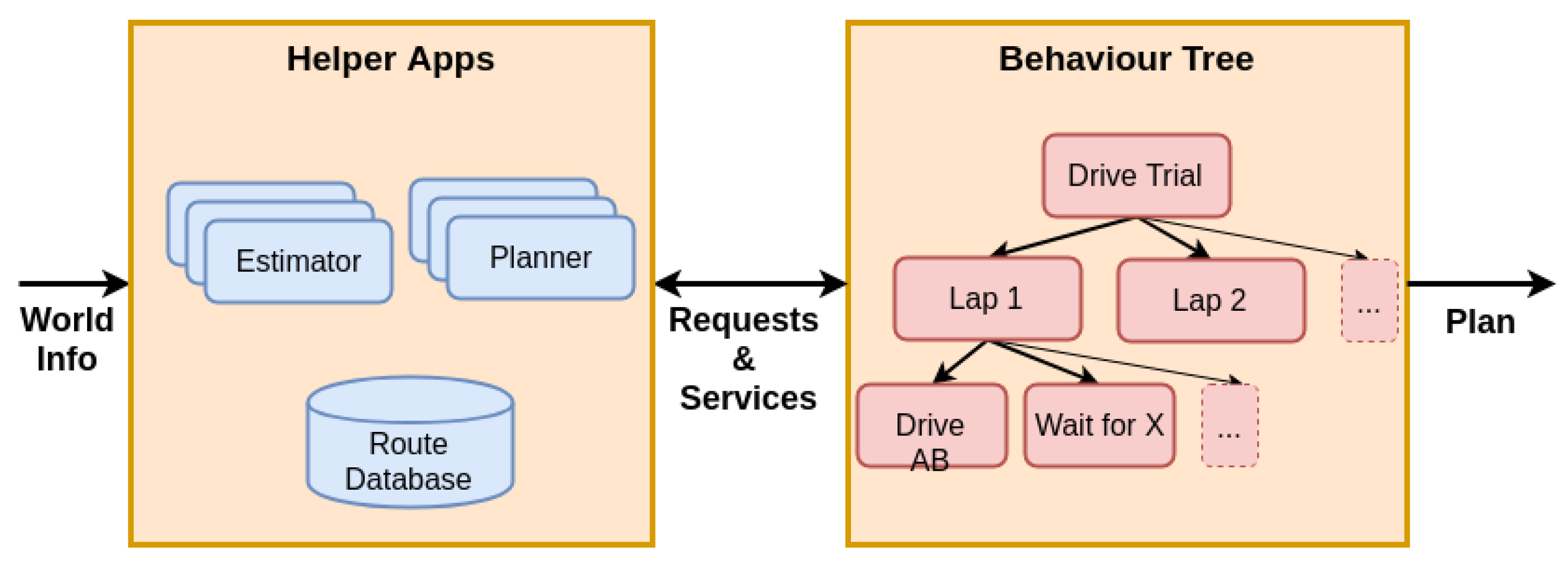
The DMS was implemented as a collection of interacting applications on a Dell Latitude E5550 laptop with Intel Core i7-5600 processor with four cores at 2.6GHz, 16GB RAM and a 480GB solid state drive. The laptop ran Ubuntu Linux 14.04 LTS and ROS Indigo. The DMS applications used ROS [
21] for communicating with each other using ROS
topics and
parameters, using the architecture shown in
Figure 4.
Numerically intensive applications such as estimators (e.g., the determination of triggers from raw sensor data) and planners (e.g., the calculation of paths for lane changes) were hence kept separate from the behaviour tree, avoiding the need for heavy computation in the tree and transfer of extensive raw sensor data to the tree’s ‘blackboard’ data structure. External components were interfaced via a wired Ethernet, enabling direct communication to sensors and ROS communication to on-board computers for the Wildcat’s lower-level pilot controller and its sensing subsystem. Bringing the Wildcat pilot computer into the same ROS ecosystem as the DMS enabled the safety driver to view live status information on a dash-mounted display. ROS visualisation tools were used to show graphical plans (via the ROS visualisation tool rviz) and textual status updates (via the ROS log introspective tool rqt_console). The rosbag facility was used to record all data exchanges for bulk storage, offline diagnostics and to support development. This was particularly helpful for trigger tuning and behaviour tree development, as recorded data could be played back through the same interfaces to test modified software components.
5.4.1. Trial 2 Experiences
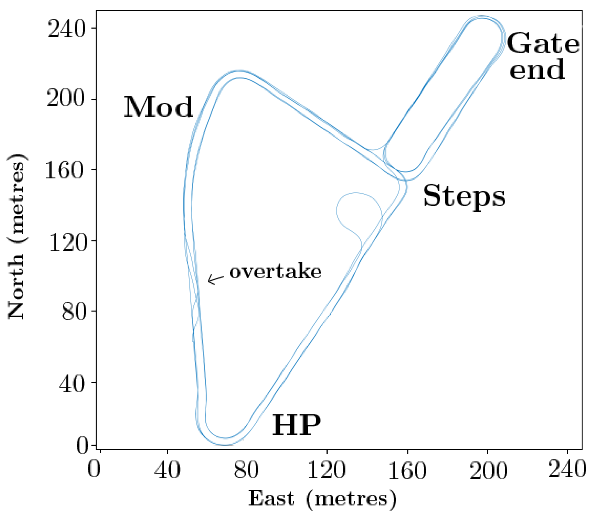
Figure 5 shows the GPS positions recorded during one “cycle” of Trial 2, involving four “laps” with varying routes and interactions. For clarity axes are in metres relative to an origin point in the bottom left. Four location identifiers are annotated: these were found to aid understanding and radio communication and were chosen to represent local landmarks. The interactions with other vehicles took place at the T-junction at location “Steps”. The crossovers between tracks seen between locations “HP” and “Mod”, markerd with an arrow illustrate the manoeuvre to overtake a parked car, which was moved into place after the first lap. This location also included an interaction with an oncoming car prior to the overtake in one of the laps.
5.4.2. Lessons Learned for DMS
The behaviour tree approach succeeded in providing the necessary modularity to support rapid prototyping of three different scenarios. This is in keeping with long-standing robotics results showing the robustness and usability of a behavioural approach.
The operational demands of participant trials and technology development are diametrically opposed. The former demands high reliability and repeatability, whereas the latter inherently introduces higher risk through the insertion of new capabilities. Therefore, later in the project this pressure was alleviated by carrying out technology development as a separate activity that included technology demonstrations to showcase new AV capabilities. Those developments were then exploited later in the project once stabilised, and incorporated into trial activities.
Integration of technology capabilities was the hardest part of the challenge by far. For example, with sensors and decision-making crossing organisational boundaries (Fusion, BAE and BRL) the DMS was only able to encounter real perceptual uncertainty once these parts of the technology were integrated. Challenges including mitigating detection (e.g., car visibility in LIDAR) and timing challenges (e.g., interacting car passing before detection activated). The architecture (see
Figure 4) closed a critical feedback loop around a chain of three separately provided capabilities. Mandating standard interfaces went some way to easing the final integration process, but subsystem performance requirements were not captured. More quantitative approaches to requirements decomposition can help ensure that subsystem performance requirements are captured but such approaches can sometimes be at odds with delivering completely new capabilities.
With timescales necessitating agile development, the VENTURER trials depended heavily on practical tests for verifying integration. This was also due to the parallel development of the VENTURER vehicle simulator with the project, whereas the Wildcat capability was already existent at the start of the project. However, the Wildcat was a single shared resource, dependent on logistical and personnel support for operation, and this therefore limited the pace of integration. Additional resource limits came from availability of safety marshals, drivers (for interacting cars) and the experimental venue itself. Alternative approaches would have included more careful unit testing of individual components, intermediate integration milestones (such as desktop integration of components and tests on proxy vehicles), and a greater use of simulation to work up components prior to demanding hardware integration tests.
A more generic lesson is that the ambitious nature of projects such as VENTURER and the lean approach demanded by competitive bidding can, if care is not taken, lead to single points of failure, which can cause knock-on delays (due to late discovery of equipment shortcomings and integration difficulties). Although this state did not occur in VENTURER, a useful lesson to be learnt is that it would be worthwhile for future projects of this kind to fully embrace redundancy, i.e., it should be seen not as waste but as a route to resilient outcomes. This applies both to technical and organisational contributions.
The logistical needs of trials of this sort are only recently becoming better understood, in no small part because of projects such as VENTURER. University risk assessment approaches and the national Code of Practice provide basic standards but, in VENTURER, trial design was still heavily guided by experience and step-by-step development; essentially more trials to learn the need for more marshals. Marshal training was pivotal, as was safety driver experience, especially under the additional workload of monitoring an autonomous control system. VENTURER could have benefited significantly from significantly increased resources for integration testing; road access time, schedule time, marshals, as well as more time for practice and acceptance testing. For example, cycles of operation with frozen technology for the purposes of trust and training would have been valuable but had to be omitted due to other resource constraints.
6. Sensing
It is important to make a distinction between ‘sensing’, and ‘perception’ or ‘recognition’. Our eyes are sensors of colour and hue, but it is very complex perception systems in our brains that turn the sensed signals into recognition of discernible objects around us. For the VENTURER trials, multiple sensory modalities were used at all times, in an integrated manner, to attain perceptions of the world outside the AV under test. The VENTURER technology design team decided that an external object detection ‘perception’ subsystem would be created, and significant time was needed to drive the Wildcat around the testing area so that the many and various on-board sensor and control sub-systems could be tested and tuned up. Allowing sufficient time for system tuning is an important lesson learned from the VENTURER project. The decisions alluded to above resulted in all the sensors detailed below in
Table 1 being fitted to the Wildcat for Trial 3 and thereafter; they consisted of the primary sensing and perception units from Fusion Processing as well as the BAE Systems back-ups. The primary sensor suite, furnished by Fusion processing, uses multi-modal sensor fusion to both sense and recognise objects, whereas the backup system was used to sense the presence of objects but could not identify them.
6.1. Fusion Processing Technology Development
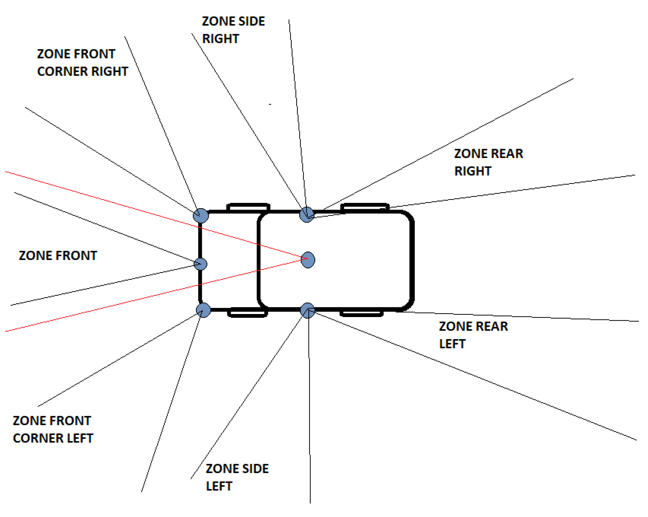
The image in
Figure 6 shows roughly what these data capture zones looked like, with respect to the field of view of each of the sensors in the Fusion system. However, it should be noted that there were no ‘blind spots’ between zones, i.e., for reasons related to IP protection this diagram does not accurately represent the actual field of view of each Fusion sensor, only a good general impression of the overall layout and orientation of the sensors that were deployed. The sequence of zone triggers would indicate to the DMS that the object of interest had been successfully detected. For example, an oncoming cyclist that passes the right side of the vehicle would first occupy then clear the front zone, followed by the front corner right zone, the side right zone and finally the rear right zone. In the same way a pedestrian crossing the road in front of the Wildcat from left to right, would occupy then clear the front corner left zone, followed in turn by the front zone and finally the front corner right zone.
6.2. Example Fusion Processing Scenario
While many interaction scenarios were tested as part of the three trials in this project, this paper focuses specifically on one of the more complex interactions, representative of typical scenarios.
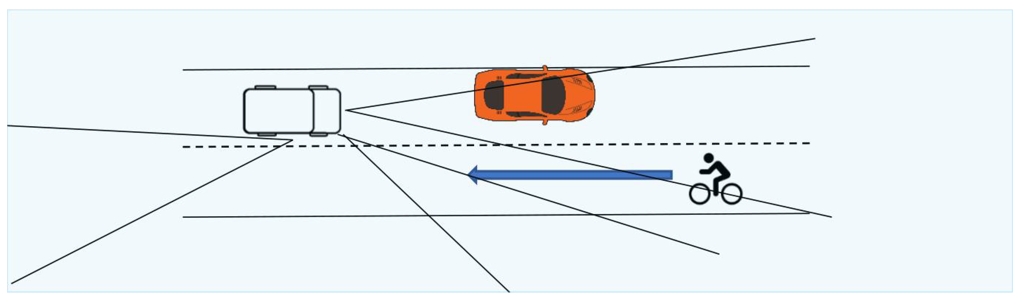
This interaction scenario is titled the ‘Cyclist Parked Car Pass’. As the diagram
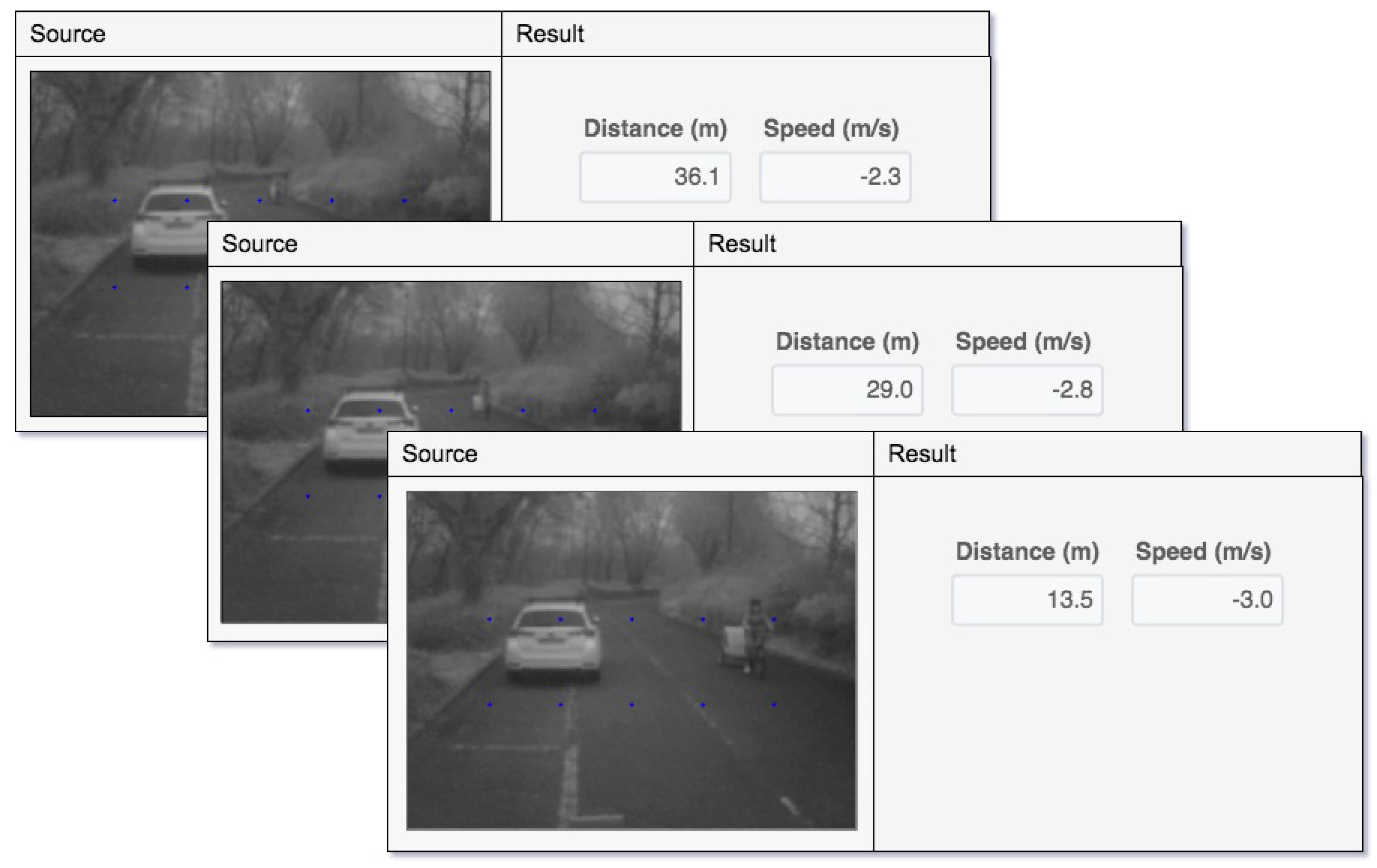
Figure 7 shows, this scenario consisted of the Wildcat waiting behind a car obstructing the road ahead, while a cyclist approaches in the oncoming lane. The sensors must detect the cyclist’s approach to prevent the Wildcat overtaking the parked car until the cyclist has passed. As the image shows, the sensor zones used in this scenario are the front zone, the front right corner zone and the rear right zone. The cyclist is initially tracked by the forward radar sensor, then picked up by the front corner sensor as they pass the Wildcat, and finally by the rear right sensor indicating that they have passed the vehicle. The series of images in
Figure 8 show the cyclist initially detected at a range of 36 m ahead, 3.8 degrees from the forward direction and travelling an approach speed of 2.3 m/s (5.14 m/h) and tracked down to a range of 13.5 m, 10.1 degree offset, and now travelling at 3.0 m/s (6.7 m/h).
7. Wireless Communication System Demonstration Using a Bus
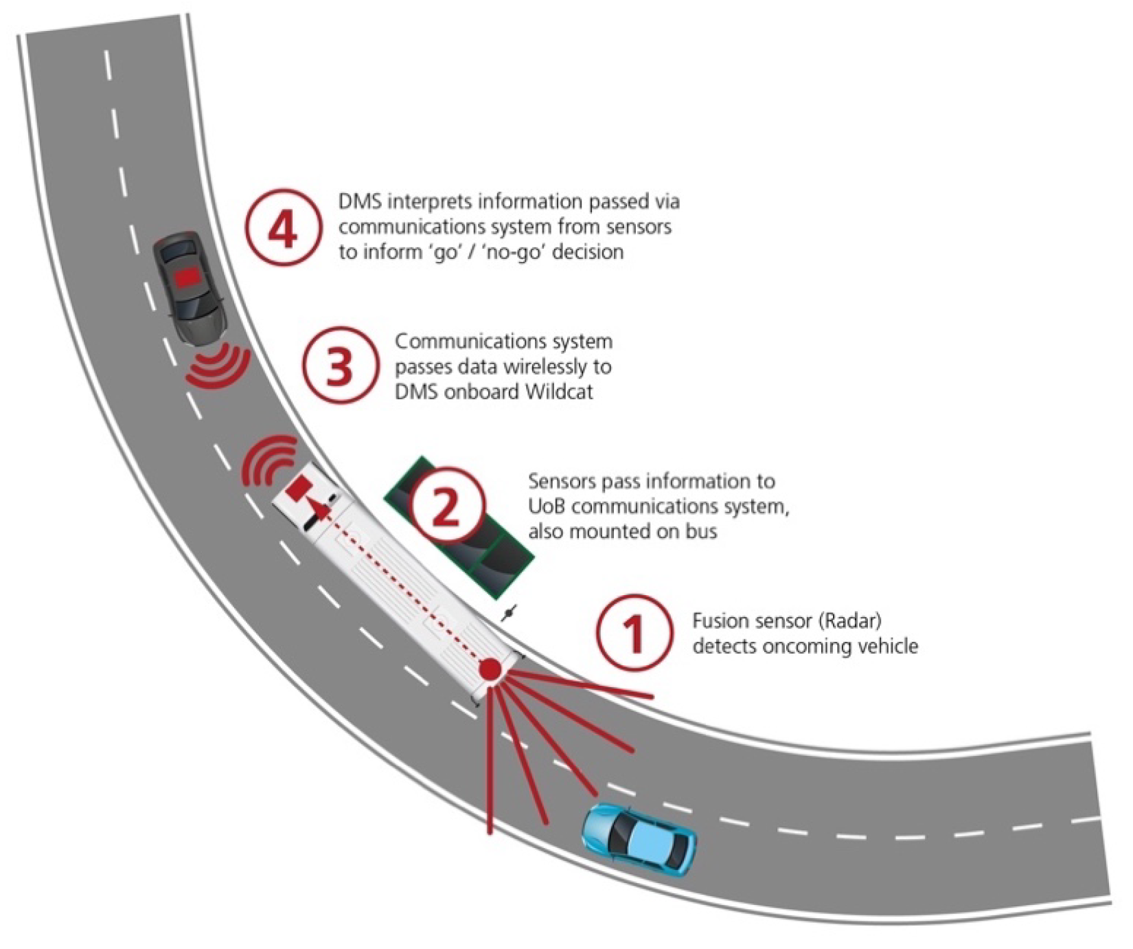
To illustrate the wireless communications capabilities that were considered in VENTURER, we developed a third scenario, involving the AV passing a stopped bus, potentially in the presence of oncoming traffic. Here a dedicated communications link was used to enable information to be transferred from the sensors on the bus to the Wildcat. In this scenario, the Fusion Processing radar sensor sub-system mounted on the stationary bus was capable of detecting if an approaching car was about to pass and therefore a potential obstacle for the Wildcat that was waiting to overtake the bus. Under these circumstances, the bus wireless communication system transferred relevant information to the Wildcat, and then the DMS could use this transferred knowledge to ensure that overtaking was not undertaken. This process is illustrated in
Figure 9.
This technology demonstration re-used many components from Trials 2 and 3, with a simple re-arrangement of the behaviour tree, and facilitated by a standard ROS connection. The University of Bristol provided their expertise in communications systems to enable various aspects of the VENTURER trials. The main task here was to enable a robust wireless connectivity for Vehicle To Infrastructure (V2I) and Vehicle To Vehicle (V2V) communication. ITS-G5 equipment provided by Siemens was used to prototype the wireless connectivity.
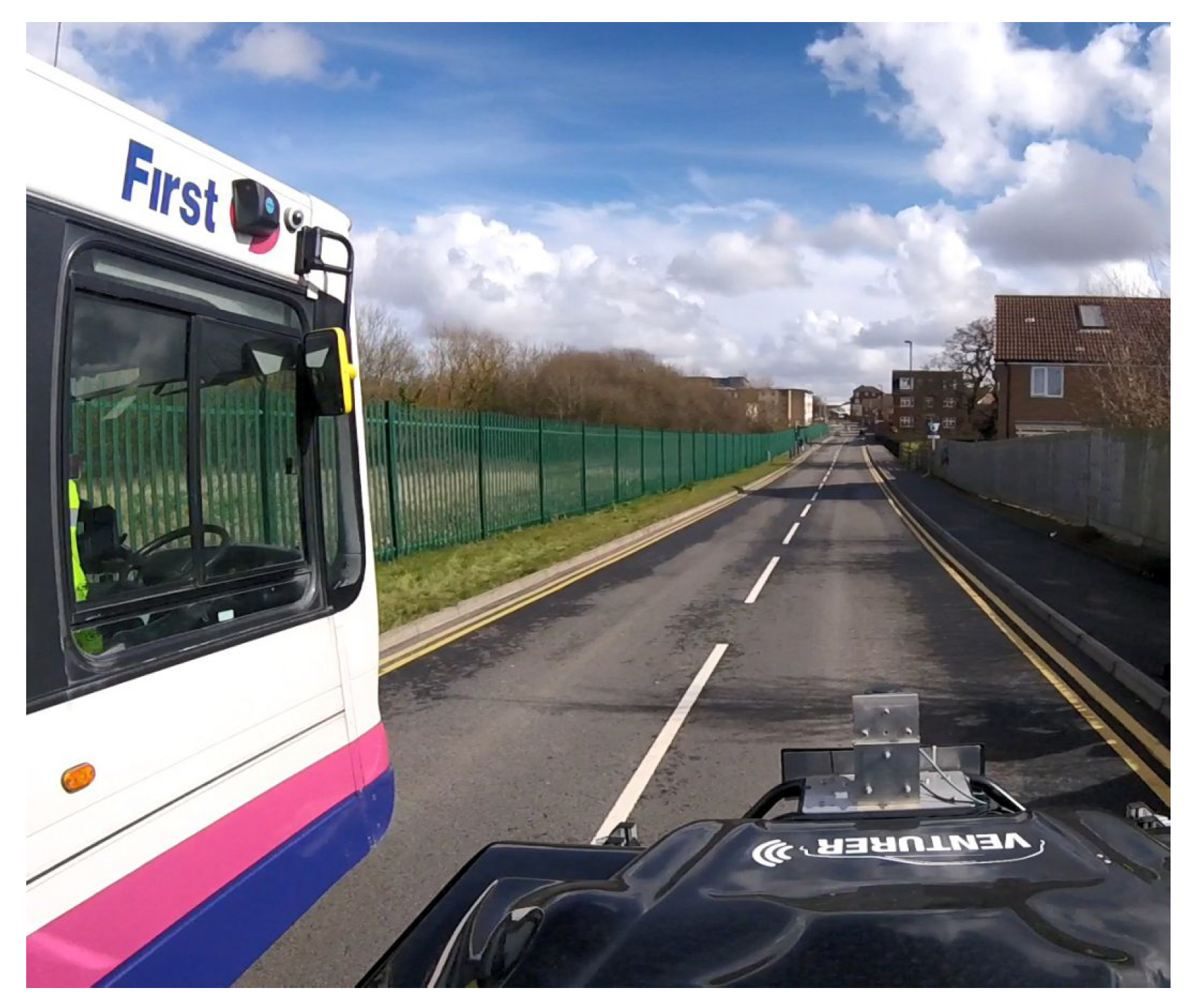
This demonstration was conducted on a section of South Gloucestershire roadway, called Long Mead, as seen in
Figure 10. The ‘look ahead’ capability used the communications system to pass information about the road ahead to the Wildcat, which had occluded visibility.
Additional work would be required to secure the messages from spoofing and other malicious or unintentional communications interference since the current approach does not guarantee security from malicious devices sending a ‘clear’ message and the protocol does not include a method to ensure trust that the message is accurate, current and was received.
This demonstration was only intended to provide one simple illustration of the potential for improved road safety and efficiency that could result from the use of V2V and/or V2X wireless communications systems in the future. There is clearly a great deal more work that is needed in this area and, indeed, large sections of later the Centre for Connected and Autonomous Vehicles (CCAV) funded projects are and will be focused on this aspect of CAV research and development. However, it remains a powerful demonstration of what could be possible.
8. Project-Level Lessons Learned
The focus of this article is on development of the integrated technological base for the trials and other experiments that were to be conducted. However, VENTURER itself emphasised the human factors aspects of the introduction of the technology. Several generic lessons were learned through the execution of this substantial cross-disciplinary project; some more unexpected than others. Below we briefly outline those lessons for the benefit of the reader.
First of all, if one assumes that, such as VENTURER, a future project will be concerned with investigating some novel aspects of the technology itself as well as human factors aspects of the use of that technology, then one must ensure that an adequate overall plan is in place to assess success in both. It is recommended from our experiences in VENTURER that one should start by making detailed plans of the human factors aspects that will be investigated. Once the former aspect is clear, then it will be critical to devise a programme of appropriate experimental scenarios to carry out those human factors aspects of the investigation. After that, it will be critical to consider the technology required to construct those scenarios. If some of that technology is novel and worthy of experimental assessment in its own right, then a set of experiments should be devised to assess that technology. There may, but may not, be overlap between the experimental scenarios generated by human factors considerations and those generated by technology assessment investigations.
In other words, it is critical to keep the human factors oriented investigations separate from the technology assessments where necessary, and especially when the aims of one of these aspects could compromise the other. For example, most human factors oriented experiments will require a completely stable technology infrastructure so as to be able to repeat experiments with multiple participants with as little variation as possible. To ensure this, it may be necessary to carry out experimental assessments of the technology itself first. In all situations, it is very important to keep a clear idea of exactly what is to be assessed in each experiment.
Connected to the point above, a key learning is the need to carefully decouple the public-facing work into: (i) reporting on scientific outcomes of experiments conducted in controlled conditions and; (ii) demonstrations of the achievements of a project in open circumstances, which are typically less controllable. In other words, ensure that these two types of events are not too dependent on each other; especially avoid demonstrations that have dependencies on certain experimental outcomes that are not yet fully established.
In VENTURER all technology oriented and human factors oriented investigative experiments were conducted under controlled conditions on private roadway. This is normally much more scientifically valuable in attempting to conduct repetitive testing of equipment or different participant reactions in the same circumstances, including controlled variations of those circumstances. By contrast, although it is more difficult to arrange access to public resources such as these for experimental work, a demonstration of capability is clearly more convincing when conducted on uncontrolled publicly accessible roadway.
Carefully consider whether you should carry out experimental investigations in simulation or the real world, especially crucial if human participants are involved in risky scenarios.
Although the difficulties described below in this paragraph did not occur in the VENTURER project, it is clear that one must be careful about choosing consortium composition. Although research consortia must clearly be constituted from partners that have something valuable and unique to contribute, good collaborating partner communication and empathetic programme leadership are also essentials from the outset.
9. Summary and Recommendations
The VENTURER project systematically assessed the responses of passengers and other road users, including pedestrians and cyclists, to Autonomous Vehicles (AVs), in a successfully executed series of controlled but increasingly complex trials and demonstrations in urban settings. In addition to the social, insurance and legal aspects that have been investigated (and reported on by the VENTURER consortium members elsewhere), the trials themselves provided a greater understanding of how AV technology performs. Developing these understandings has provided some key steps towards facilitating the deployment of AVs on UK roads.
In order to conduct human factors experiments in the Autonomous Vehicle sector under consistent and repeatable conditions that lead to statistically significant results within typically tight time constraints, one needs to define a scripted and stable set of scenarios that uses well integrated and reliable equipment and a controllable environmental setting. This requirement can often be at odds with also making significant technology developments, and so it is important to recognise that, if both are part of a project’s goals, they may need to be separated from each other.
It is clear that vehicle perception capabilities will be a critical component of the overall safety of AVs. In turn, sensor fusion is a critical component of building a robust sensor-perception pipeline. A great deal of valuable work has already been achieved in this highly complex domain, with significant contributions from the partners working in this project but, since this is such a complex and rapidly evolving area, there is much more still to be done.
Although the bus demonstration was only a simple exemplar, with respect to connectivity, Venturer illustrated the potential for improved road safety and usage efficiency that could result from the use of V2V and/or V2X wireless communications systems in the future. However, there is clearly a great deal more work that is needed in this area also, especially in the area of communication security.


