
Freeze-Thaw Behaviour of Post-Installed Bonded Anchors under Changing Climate Conditions


Institute for Structural Engineering, University of Natural Resources and Life Sciences Vienna, Peter Jordan-Street 82, 1190 Vienna, Austria
*
Author to whom correspondence should be addressed.
CivilEng 2022, 3(2), 332-346; https://0-doi-org.brum.beds.ac.uk/10.3390/civileng3020020
Submission received: 18 March 2022
/
Revised: 2 April 2022
/
Accepted: 8 April 2022
/
Published: 10 April 2022
(This article belongs to the Special Issue Connections in Concrete Volume 2)
Abstract
:The freeze-thaw behaviour of bonded fasteners in concrete is assessed according to the European Assessment Document 330499-01-0601 with freeze-thaw condition tests, which include 50 temperature cycles with a duration of 24 h between −20 °C and +20 °C on constantly loaded anchors. It is assumed that one cycle is equivalent to the temperature difference, which a bonded fastener undergoes in one year. Based on an analysis of a 28-year time series of air temperature data for Austria respecting the Alpine region, a modified test protocol with a temperature amplitude of 65 °C between −20 °C and +45 °C is compiled without a predefinition of the number of cycles, in order to simulate temperature differences that occur under real climatic conditions. The experimental test results obtained for both test procedures demonstrate that the stabilization of the displacements for the modified test series occurred after 185 temperature cycles, compared to the 50 cycles for the standard method. This means that an increase in the temperature amplitude of 25 °C in the higher temperature range leads to an approximately 3.5 times higher number of required temperature cycles until displacement stabilization is reached. It is concluded that the definition of the used temperature range for freeze-thaw testing in conjunction with climatic data should be critically considered, in order to possibly adapt pure freeze-thaw tests towards experiments that take into account real annual temperature differences.
1. Introduction
1.1. General
Bonded anchors are systems that are used for the post-installed anchorage of loads in various fastening structures. The base material for these structures can be unreinforced and reinforced concrete or masonry. Bonded anchors usually consist of a metal element that is inserted into a drilled hole filled with adhesive mortar. After an appropriate curing time, an admissible load can be applied [1,2].
For safety-relevant applications, fastening systems tested and assessed according to the European Assessment Documents are used in the European economic area. In particular, EAD 330499-01-0601 [3] regulates the qualification of bonded anchors and the derivation of the essential characteristics of the fasteners. For the US market, the assessment of bonded anchors is conducted according to AC308 and ACI 355.4, respectively [4,5].
Bonded fasteners are known to be adversely affected by sustained or cyclic long-term loading and different environmental exposures due to the inherent long-term behaviour and degradation of the different involved materials concrete, adhesive mortar and anchor steel [6]. Therefore, the long-term product behaviour of bonded fasteners is extensively examined during the product-qualification process according to EAD 330499-01-0601 [3]. The prescribed test programme can be divided into tests related to in-service factors (elevated temperature and freeze-thaw conditions), tests related to the adhesive (mixing effort, adhesive curing time, chemical resistance to alkalinity and sulphur dioxide) and tests related to installation factors (installation temperature, hole orientation, hole cleaning and moisture in installation), as provided in [7]. This paper focuses on the freeze-thaw condition tests, which are a part of in-service factors together with elevated temperature.
In general, laboratory tests can only be simulations of in situ conditions and acting environmental exposures under defined boundary conditions during the working life of a bonded fastener. The duration of experimental tests for assessing the long-term performance of products during their working life is limited and can only represent a small portion of the whole working life. As a consequence, two different approaches can be used to simulate the long-term behaviour. On the one hand, extrapolation techniques can be used to forecast a measured behaviour to certain time horizons and on the other hand, severe testing conditions to accelerate an ageing process can be used.
The standard procedure for freeze-thaw condition tests according to [3] prescribes that 50 cycles between −20 °C and +20 °C with a duration of 24 h for one cycle have to be performed on constantly loaded bonded fasteners. It is assumed for the purpose of this investigation that one freeze-thaw cycle is equivalent to the temperature difference, which a bonded fastener undergoes within one year. There is the recommendation for a careful design of the tested freeze-thaw cycles in [8,9], indicating that the number of freeze-thaw cycles should be defined based on recorded climatic data. The aim of this work is to investigate the freeze-thaw behaviour of bonded fasteners subjected to a constant tension load, and also tries to simulate realistic climatic conditions based on a time series of meteorological data for Austria. It can be assumed that the temperature range measured might be similar to the whole Alpine region.
The definition of the test parameters for freeze-thaw tests originated in the 1980s, whereby, the exact basis respects the assumption of the environmental conditions, based on former conditions. However, for an increase in the working life of existing fasteners or a longer planned working life of new fasteners, these fundamentals are highly relevant. Furthermore, it is completely unknown, and therefore the subject of this paper, how changing climatic conditions affect the number of freeze-thaw cycles in a predicted lifetime and hence a bonded anchor is also exposed in the tests.
This article analyses in detail whether the test parameters and input variables assumed in the guidelines are still justified as a result of climatic changes. For this purpose, an analysis is carried out on the basis of climatic data from urban and alpine areas in Austria to determine whether the freeze-thaw cycles in particular may still be considered valid for these, or whether an adaptation of the test regulations seems to be necessary.
In addition to a reference series based on the relevant regulations, freeze-thaw cycles were carried out to investigate the effects of external environmental influences based on the actual climatic data of the weather station “Hohe Warte” in Vienna. In these experiments, the bonded fasteners were subjected to a daily freeze-thaw cycle in order to simulate the real climatic effects. The exact derivation of the test parameters based on the accumulated meteorological data and their influence on the evaluation of the tests are discussed in detail in the following chapters.
1.2. Literature Review of Selected Environmental Influences
Rehm [10] published the results of freeze-thaw tests on bonded anchors using two different types of adhesive mortar in 1985. These investigations were carried out on both an unsaturated polyester resin mortar and a vinyl ester resin mortar. The test series demonstrated that the displacements on the bonded anchors stabilised after approx. 40 freeze-thaw cycles when applying a constant load on bonded anchors of vinyl ester resin mortar. In contrast, when unsaturated polyester resin mortar was used, a further steady increase in bonded anchor displacements was observed [1,10,11]. Furthermore, [10] gives indication that the measured short-term bond strength from the reference tests of bonded anchors based on unsaturated polyesters decrease to approx. 50% of the reference value after long-term exposure to tensile load and freeze-thaw cycles, whereas a decrease of only approx. 10% is observed for bonded anchors based on vinyl esters.
The effect of different environmental influences on the load-bearing behaviour of bonded anchors in concrete is investigated in [12,13]. The simulated environmental influences were (1) UV light, (2) freeze-thaw cycles, (3) corrosion in pH neutral salt solution, (4) wetting and drying to simulate acid rain and (5) a combination of several influences (freeze-thaw, corrosion and wetting and drying). The load-displacement behaviour of the environmentally exposed bonded anchors was subsequently compared with that of bonded anchors without exposure to simulated environmental influences. The test results varied substantially depending on the type of scenario simulated by the test programme. For the bonded anchors exposed to UV light, no significant influence of the load on the working life could be demonstrated. Similar results were observed for the scenarios “corrosion in pH-neutral salt solution” and “wetting and drying to simulate acid rain”. In the case of bonded anchors, which had passed the 50-day freeze-thaw cycles, an influence was observed. In the case of a practical construction application, the infiltration of water into the borehole should therefore be minimised in order to avoid any early bond failure. This can be achieved particularly by maintaining a sufficient edge distance of the bonded fasteners. It can be concluded, based on the investigations in [12], that the occurrence of freeze-thaw cycles or alternating moisture and temperature effects have a great influence on the working life and load-bearing behaviour of bonded anchors. During the working life of a bonded fastener, there is a combined effect of moisture and temperature. These parameters also occur in parallel, which means that their influences on the load-bearing behaviour of bonded fasteners overlap.
Bowditch [14] shows that the influence of humidity is increased by the temporally parallel phenomenon of elevated temperatures. Hand et al. [15] also report that adhesive mortars have a greater tendency to absorb water at elevated temperatures in combination with moisture than at room temperature. This combined effect has negative influences on the bond strength of the bonded anchors in the test case and also in practice [15].
This trend was also confirmed by Feng et al. [16] in 2005 by means of tests on two different adhesive mortar systems. Thereby, the bonded anchors tested under the influence of moist conditions show a lower stiffness than dry samples at any tested temperature. Independently of the initial stiffness of the bonded anchors, moist conditions also lead to a disproportionate decrease in the stiffness with increasing temperature [16].
Further evidence of the negative influence of combined humidity-temperature exposure on the load-bearing behaviour of bonded anchors was provided by creep tests on bonded anchors based on one vinyl ester resin mortar and two epoxy resin mortars [17,18]. El Menoufy [17] reports results of creep tests on bonded anchors subjected to permanent loads of 40% and 60% of the short-time strength τ at (1) room temperature, (2) in dry and (3) damp ambient conditions respectively, as well as (4) tests with freeze-thaw conditions. The results confirm that at high loads, combined with the influence of moisture or freeze-thaw cycling, the adhesive anchors show an increased creep behaviour.
The freeze-thaw behaviour is also relevant in other areas and for different building materials. Especially for concrete and fibre-reinforced concrete or for strengthening of concrete structures with externally bonded prestressed carbon-fibre-reinforced polymers (CFRP), there is lots of recent literature about the freeze-thaw behaviour available [19,20,21,22,23], in comparison to bonded anchors.
1.3. Intent of Research
In the definition of the test procedure, the freeze-thaw cycles to which bonded anchors are exposed in testing are assumed as annual cycles. In many cases, depending on their intended use, bonded anchors are exposed to the environment in a relatively unprotected manner. Therefore, temperature changes are of particular interest in order to investigate daily freeze-thaw conditions as well. It is reasonable to assume that daily freeze-thaw conditions could have an impact on the working life of a bonded anchor exposed to weathering.
Three questions that arise in this context are:
- (1)
- Whether the temperature ranges specified according to EAD 330499-01-0601 [3] are sufficient for the testing of bonded anchors under changing climatic conditions;
- (2)
- Whether the number of cycles performed in the test programmes adequately reflect the behaviour for the predicted lifetime;
- (3)
- Consideration of locally possible extreme temperature variations as, i.e., heating areas or “micro freezing/thawing” conditions within a testing procedure.
2. Materials and Methods
2.1. Description of General Test Procedure of Freeze-Thaw Tests in Accordance with EAD 330499-01-0601
Simulated freeze-thaw cycles are intended in EAD 330499-01-0601 [3], Section 2.2.2.7 to generally test the functionality of bonded anchors under changing environmental or climatic conditions for a working life of 50 years.
Freeze-thaw cycles are to be carried out in appropriately durable uncracked concrete of concrete class C50/60, according to the specifications of [3], as test specimen cubes or cylinders are used. The splitting of the concrete specimen shall be prevented by suitable reinforcement or jacketing.
In order to create appropriate climatic conditions, the surface of the specimen shall be covered with a layer of water of at least 12 mm in height. All other unprotected surfaces must be sealed to prevent evaporation of the water.
During the entire test period (i.e., during the corresponding number of freeze-thaw cycles), the fastener is loaded in a confined test setup with a constant tensile load Nsust calculated in accordance with Equation (1).
where Nsust is the applied constant tension load during the conduction of tests, τRk,ucr,60 is the characteristic bond strength for uncracked concrete C50/60 derived from other test series, d is the diameter of threaded rod (d = 12 mm), hef is the effective embedment depth and γinst is the installation partial safety factor.
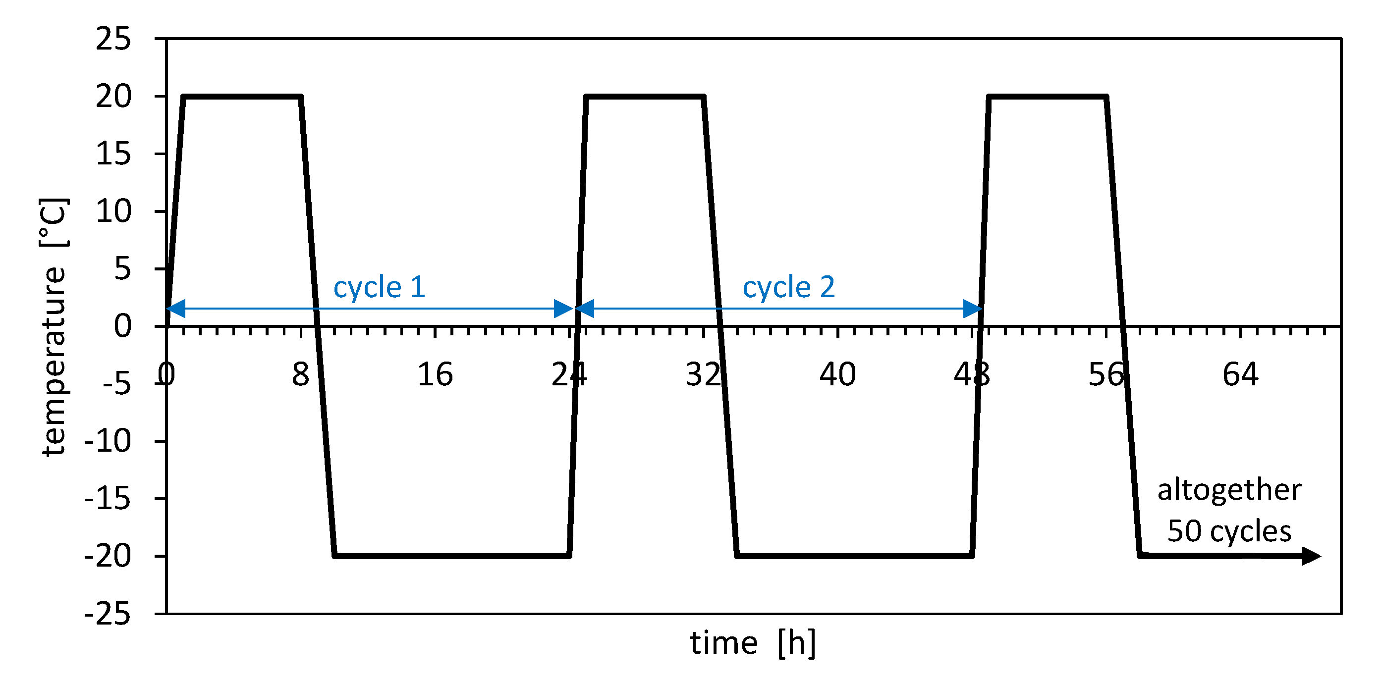
The 50 freeze-thaw cycles must be performed in a suitable climate chamber. A freeze-thaw cycle consists of two parts and is continued immediately after its completion: (1) increase in the internal temperature of the climate chamber to +20 °C (±2 °C) within one hour; this temperature is maintained for 7 h; (2) decrease the internal temperature of the climate chamber to −20 °C (±2 °C) within two hours; this temperature is maintained for 14 h, as it is shown in Figure 1.
In case of an interruption of the test programme, the test specimens have to be stored at an ambient temperature of −20 °C (±2 °C) until the test can be continued [3]. The tests are performed with the confined test setup, which means that the formation of a concrete breakout is prevented and bond failure either between mortar and steel part or concrete and mortar is constrained. After the completion of the temperature cycles, the bonded anchors are loaded up to failure at the normal ambient temperature.
During the application of the constant tension load in the freeze-thaw cycles, the displacements of the bonded anchors with a reference basis to the concrete surface are measured, e.g., by using analogous dial indicators. An evaluation has to consider if the increase in the displacements has already stabilised, or if the displacements are still increasing.
For a successful assessment, EAD 330499-01-0601, Section 2.2.2.7 requires that the displacement increase shall be reduced with an increasing number of cycles almost to zero.
Additionally, the mean value of the residual load capacity tested with a confined test setup after the completion of the freeze-thaw tests has to be compared to the reference tests without being subjected to freeze-thaw conditions. The ratio of τfreeze/thaw/τref must be at least α = 0.9.
2.2. Adjustment of Freeze-Thaw Tests as a Result of Changing Climate Conditions
The aim of this section is to define a modified test programme for freeze-thaw cycling tests. The adjustment is based on meteorological data from Austria and will be conducted in comparison to the current standard test programme in accordance with [3].
The meteorological data from two different locations in Austria were both analysed and evaluated in order to assess the variety of the climate in Austria. Care was taken to ensure that the two locations at which the local climatic conditions are evaluated have geomorphologically relevant differences.
The locations studied are Hohe Warte in Vienna (198 m.a.s.l.) and Sonnblick in Salzburg (3109 m.a.s.l.). The motivation for the choice of the sites mentioned is that an urban area (Hohe Warte) and an alpine area (Sonnblick) are covered.
This allows the identification of differences in local climatic conditions in Austria and similar regions and, subsequently, the resulting different climatic effects on structures and buildings. Based on the available data from ZAMG [24], an analysis of the selected relevant weather data of the last 28 years (1992–2019, Hohe Warte) and 24 years (1996–2019, Sonnblick) of the associated meteorological stations were executed. This includes daily measured values of air temperature, relative humidity and precipitation. The air temperature data are most relevant for this contribution.
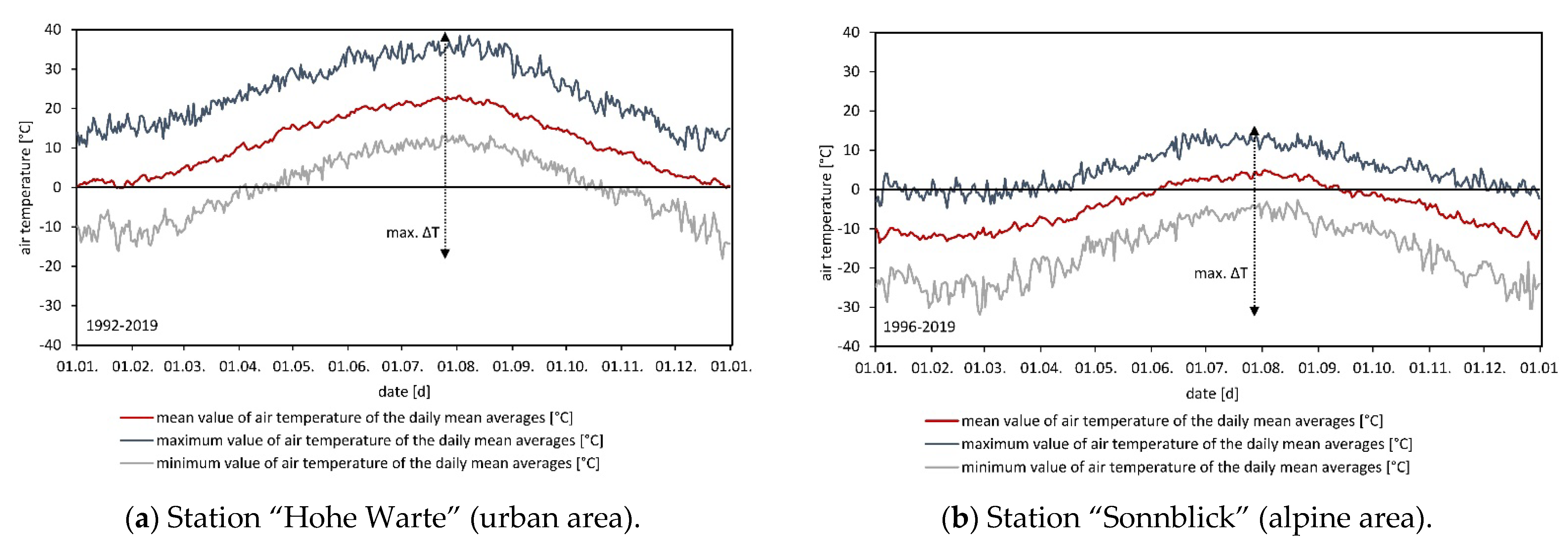
The measured air temperature curves of the respective weather stations are shown below, in Figure 2a,b. The orange line indicates the mean temperature curve on a daily basis over the observation period. The upper line represents the daily maximum temperature value, and the lower line represents the daily minimum temperature value measured during the observation period of 28 and 24 years, respectively. The temperature curves obtained may be used to check whether the limits of −20 °C–+20 °C specified in [3] for the freeze-thaw test correspond to the observed situation.
Considering the temperature differences between the maximum and minimum daily mean average as decisive, Figure 2a shows a range of approx. −20 °C to +40 °C for the urban area. The alpine area shows a temperature range of approx. –30 °C to +15 °C, which is derived based on Figure 2b. It can be concluded that, particularly for applications in urban areas, the existing test programme does not fully reflect the actual air temperature difference within one year for Austria.
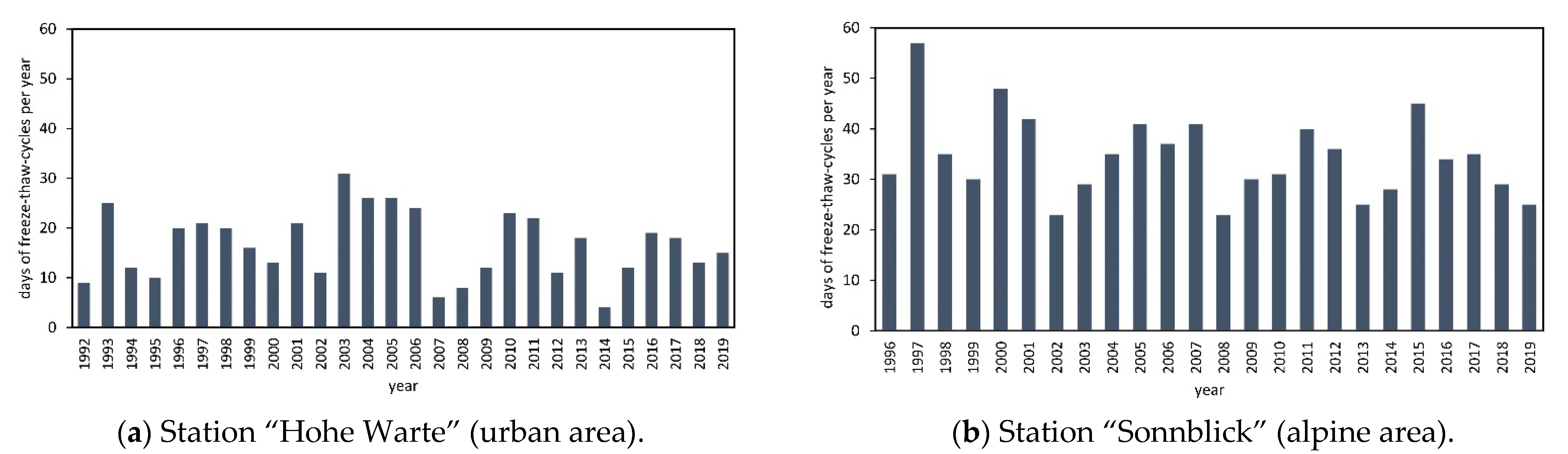
The data was also analysed in terms of how often a freeze-thaw condition occurs per year in the monitored period, whereby a temperature range of min. −2 °C and 0 °C was laid down as the definition in the evaluation process.
Figure 3a,b show the number of days with a freeze-thaw cycle for every year within the period of observation. Moreover, Becsi and Laimighofer [25] analysed the current climate for Lower Austria and Vienna for the years 1981–2010. An average of 15–20 freeze-thaw days per year was identified for the “Hohe Warte” measuring station, while a frequency of 10–30 freeze-thaw days per year was observed in the peripheral areas of the urban area. For the alpine area, as shown in Figure 3b and using the same temperature range as mentioned above, a significantly higher number of freeze-thaw cycles per year can be identified, resulting in a mean value of 35 freeze-thaw days with a maximum of 58 days in 1997.
Bonded anchors are often installed relatively unprotected from environmental exposure, depending on their intended use. Therefore, temperature fluctuations are of particular interest in order to investigate daily freeze-thaw conditions. It is conceivable that the daily freeze-thaw cycles may have an influence on the working life of a bonded anchor exposed to environmental conditions. For future research, it might subsequently be discussed whether this should be included in a test method, being aware that this will result in an increased testing effort.
Another point that should be taken into account in defining the test protocol are summer heat hotspots, which cause significantly higher temperatures in urban areas.
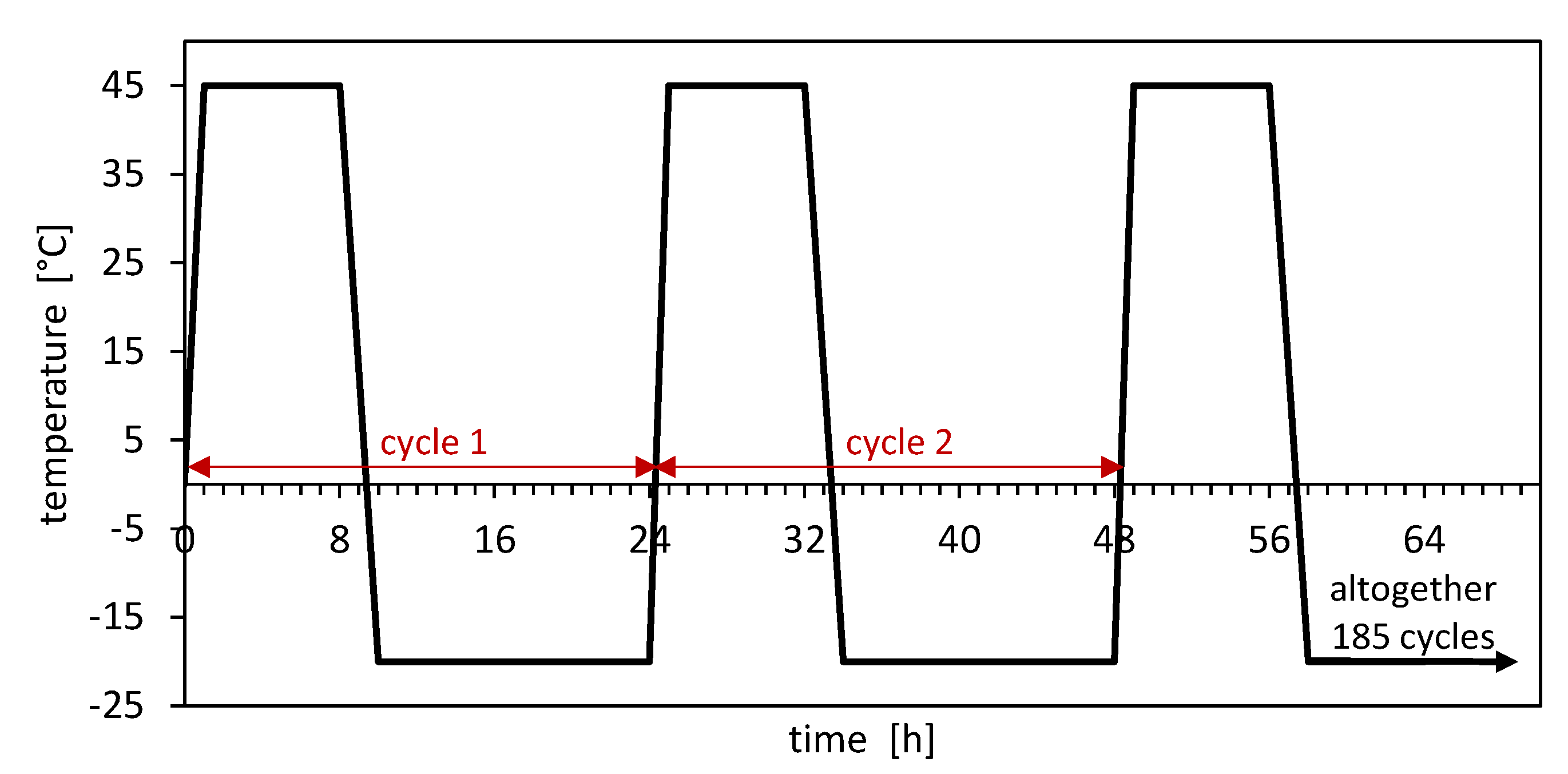
Kerestes [26] reported surface temperature measurements on façade components in Vienna in 2015. Up to 56.8 °C were measured on the sun side of concrete components, while even concrete surfaces in the shadow reached temperatures of up to 47.4 °C. Considering that such structures are potential areas of application for bonded fasteners, increased “heat stress” is to be expected here, which is likely to become more serious in the future due to ongoing global warming. The infrared measurements on concrete surfaces during the summer months can be used as a basis for a modified maximum temperature of +45 °C in the test realisation.
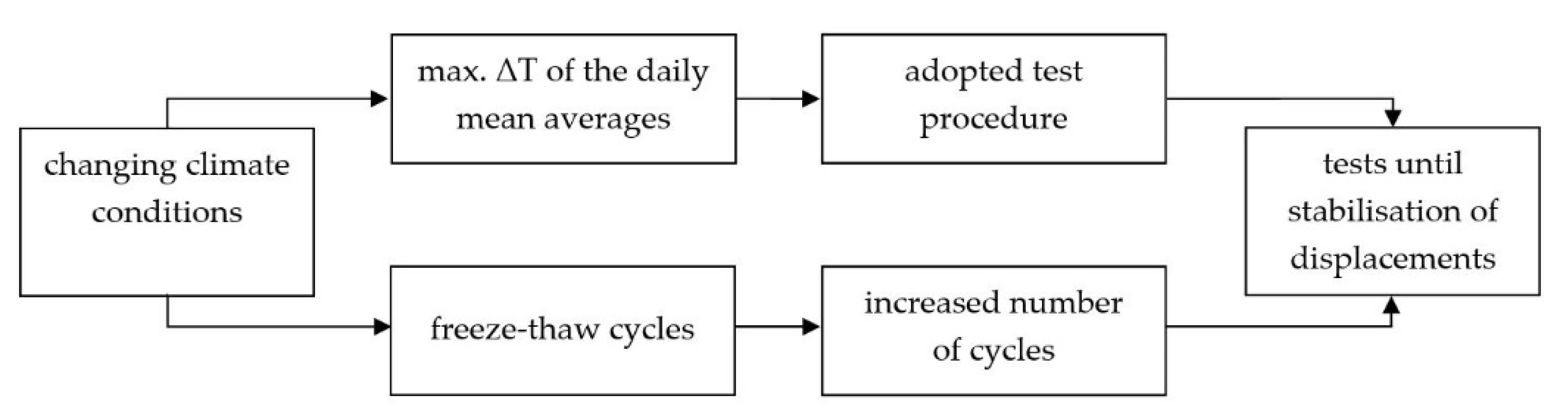
As a result of the findings of the climate data above, in a first step a modified test program for a higher temperature range is proposed. The effects from heating areas were also considered, whereas “micro freezing/thawing” conditions have been neglected in the first step. The modified test programme incorporates the previous one, i.e., the duration of the cycles and the constant tensile load to be applied remain consistent. However, the temperature cycles now cover a range of −20 °C to +45 °C. Temperature levels lower than the −20 °C in the test programme do not have to be covered, even at extreme temperatures as in the alpine region, but higher temperature ranges than the previous +20 °C have to be considered due to the overheating of urban areas in summer. The chosen modified testing procedure based on the assessment of the meteorological data for Austria is shown schematically in Figure 4. Intentionally, no maximum number of freeze-thaw cycles was specified in advance for the adjusted testing programme. Instead, the number of cycles should be determined based on the stabilisation criterion of the displacements. Experimentally, a number of 185 cycles appeared to be necessary.
For a schematic description of the approach for freeze-thaw testing, taking into account the real climate conditions, see Figure 5.
2.3. Test Setup and Conduction
Both the freeze-thaw tests according to the test programme and in compliance with the guideline, as described in Section 2.1, as well as the tests with the adjusted test programme in Section 2.2, were performed on epoxy-based bonded anchors. The permissible bond strength for this product was τRk,ucr = 16.5 n/mm2 in uncracked concrete C50/60 for temperature range I according to the corresponding declaration of performance, which is used as an input value for the constant tensile load to be applied in the tests.
Threaded rods of size M12 of steel grade 12.9 were used. The anchorage depth was hef = 60 mm, and the cleaning of the borehole was performed according to the manufacturer’s installation instructions by brushing and blowing out with compressed air.
The bonded anchors were installed in frost-resistant concrete (slab dimensions: 90 cm × 90 cm × 15 cm) of strength class C50/60 with a concrete compressive strength of fctest = 70.0 n/mm2. The mixture of the concrete consists of round aggregates, with a maximum size of dmax = 16 mm, resistances to fragmentation of a Los Angeles abrasion value of 28 and an impact value of 21. The used cement type was CEM I 42.5R in accordance with EN 197 and the water cement ratios were approximately w/z = 0.5. The grading curve of the used aggregates is within the favourable area in accordance with ÖNORM B 4710, characterising the range in which the gradation of the aggregates is at its optimum for the internal structure of the material properties.
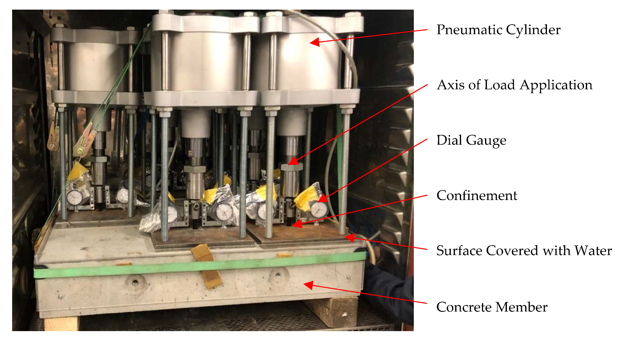
The load application of the constant tensile load of Nsust = 17.6 kN according to Equation (1) was carried out using pneumatic cylinders, which enable a constant readjustment of the applied load. The test itself was carried out with a confined test setup, as provided by the regulations. The displacements were measured on both sides using analogue dial indicators. To prevent corrosion damage, the dial indicators were packed tightly, ensuring correct displacement measurement, as shown in Figure 6. The displacement measurements, δ, defined as the vertical displacement of the anchor rod to the surface, were documented and reported at regular intervals.
Over the duration of the freeze-thaw tests, it was ensured that the top of the concrete specimen was permanently covered with a layer of water at a height of at least 12 mm. The residual load capacities Fu of the bonded anchors were determined after the freeze-thaw cycles by applying a tensile force with a confined test setup. An overview of the testing programme is listed in Table 1.
3. Results
3.1. General Overview of Test Results
An overview of the test results from the testing programme in Table 1 is provided in the following Table 2 and in Figure 7. The results of the performed tests are described in detail in the following: Section 3.2, Section 3.3 and Section 3.4.
Table 2 lists the results of the displacement measurements after the freeze-thaw cycles, denominated as δ50cycl. resp. δ185cycl. for both different testing procedures, the residual ultimate tensile loads and the corresponding displacements δFu at the residual load capacity, which can be observed as displacement at a loss of adhesion for occurred failure behaviour. In case of the freeze-thaw tests, these displacement values are not used as a criterion, but they provide useful information on the stability of the bonded anchor system. Table 2 also includes the calculated mean values for each parameter and the bond strength for each test series calculated in accordance with EAD 330499-01-0601 [3]. The relatively large deviation in the displacements, as shown in Figure 7, is a result of the typically large variations in the initial displacements, as elaborated in [27]. The initial displacement is neglected for the increasing rate of the displacements, as this rate only considers the increase from one measurement point to the other.
3.2. Tests with Freeze-Thaw Cycles between −20 °C and +20 °C (Standard Procedure)
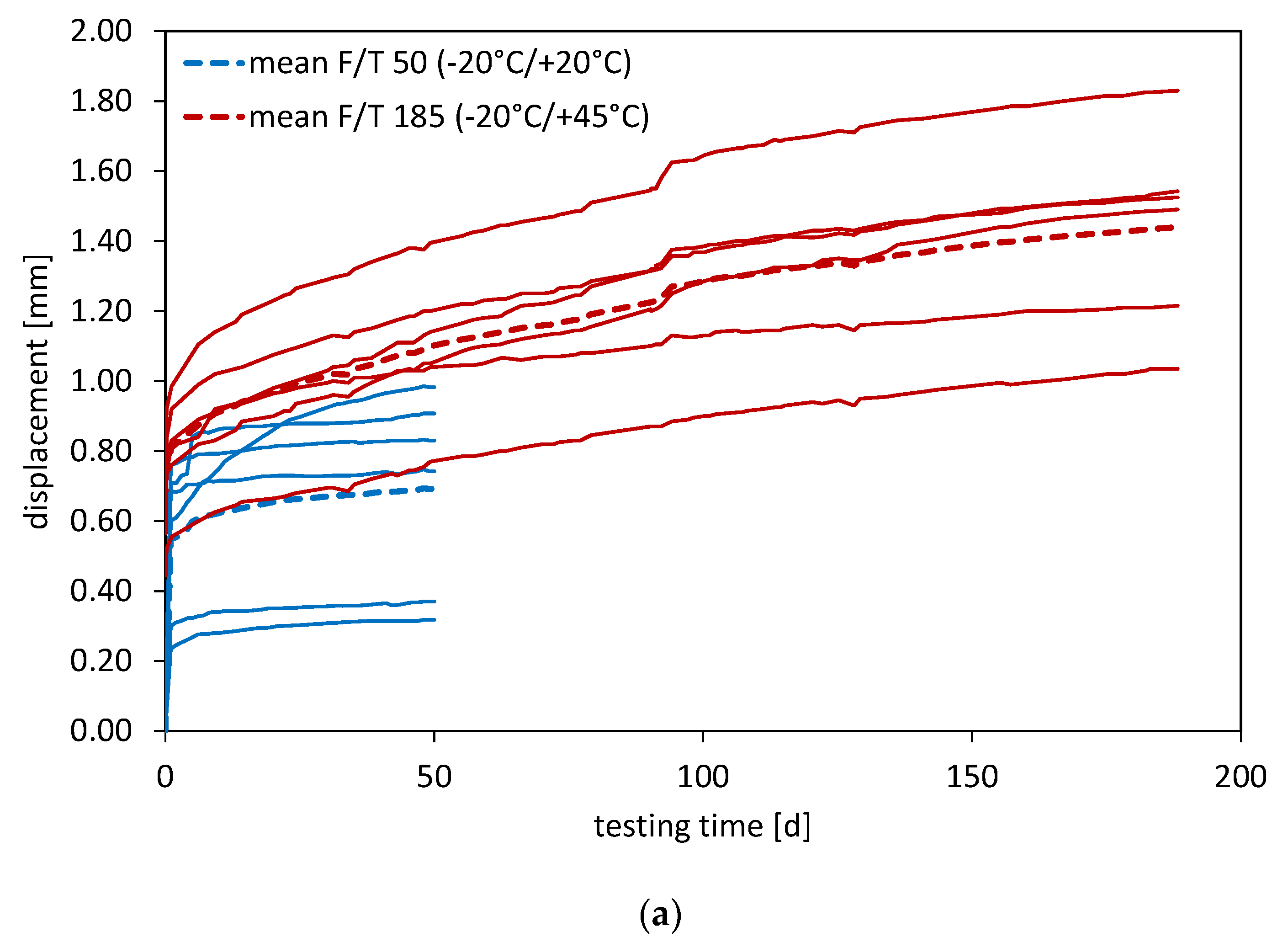
The results of these tests, as described in Section 2.1, are discussed in detail in the following. Figure 7a shows in graphical format the displacement measurements of the test procedure with 50 freeze-thaw cycles (blue lines), which was carried out according to the parameters given in EAD 330499-01-0601 [3].
The curves of the measured displacements at the individual bonded anchors demonstrate a relatively uniform behaviour. After the initial displacement is reached, the curve remains relatively constant and increases by only about 0.10 mm from the second cycle to the end of the test. After finishing the freeze-thaw cycles, the residual load capacity was determined for the six tests with Fum = 88.3 kN (CV = 9.5%); the displacement at the loss of adhesion was determined with δFu = 1.8 mm.
3.3. Tests with Freeze-Thaw Cycles between -20 °C and +45 °C (Modified Procedure)
The results of these tests as described in Section 2.2 and Section 2.3 and provided in Table 2 are presented in the following.
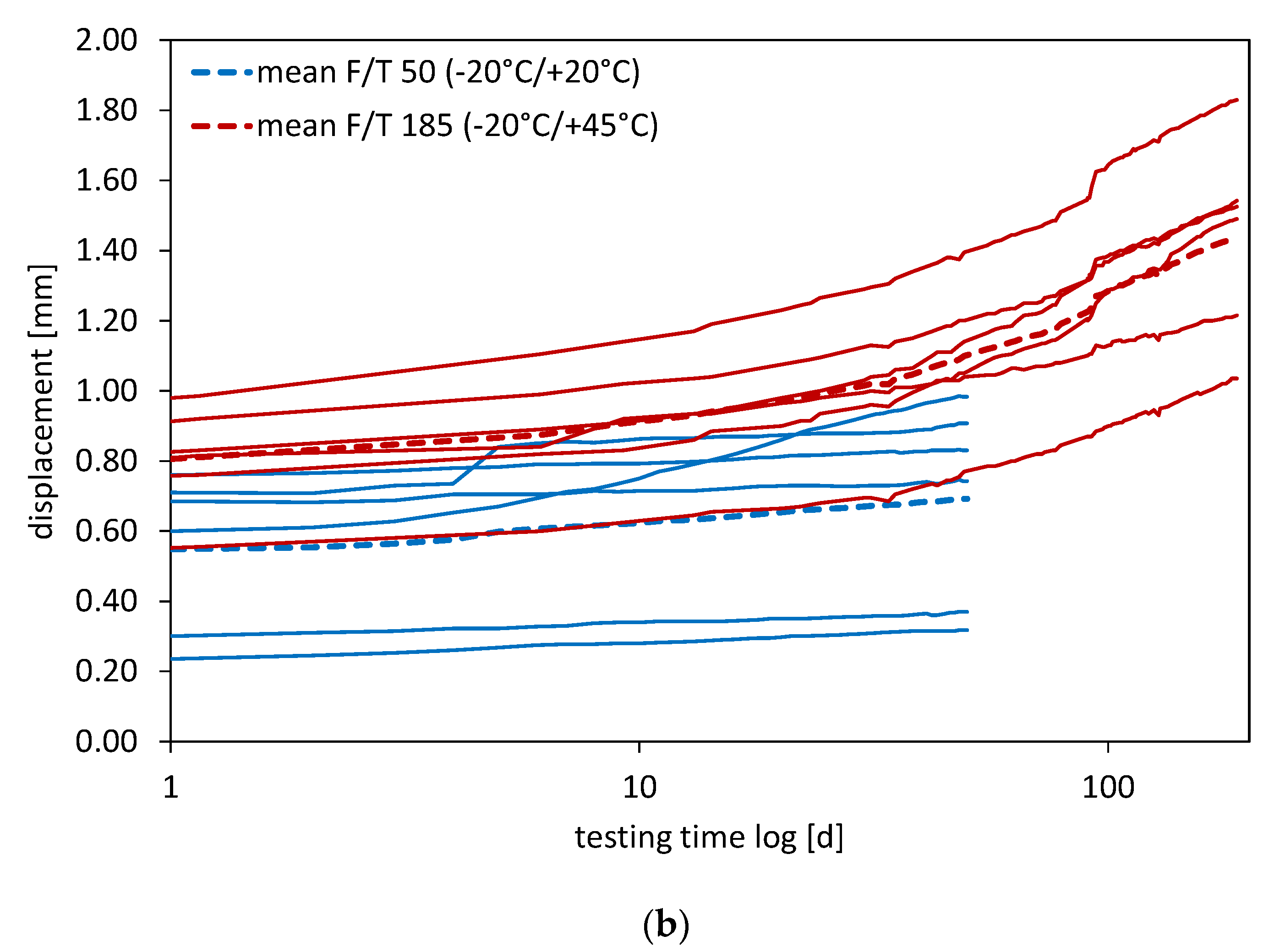
Figure 7b shows in graphical format the displacement measurements of the test procedure with altogether 185 freeze-thaw cycles until stabilisation of the displacement increase (red lines), carried out in accordance with the adjusted testing procedure.
It can be observed that in this test series, significantly higher displacements occur in comparison to the standard testing procedure according to EAD 330499-01-0601 [3], which is also as a result of the higher initial displacements. However, the displacements increase substantially over the entire duration of the experiment. The increase in displacement only decreases at the end of the test programme. The determination of the end of the test programme will be explained in more detail in the discussion in Section 4.
After the freeze-thaw cycles, the residual load capacity was determined with Fum = 105.3 kN (CV = 2.0%), and the displacement at loss of adhesion was determined with δFu = 2.7 mm.
3.4. Reference Tests without Freeze-Thaw Cycles and Sustained Loading
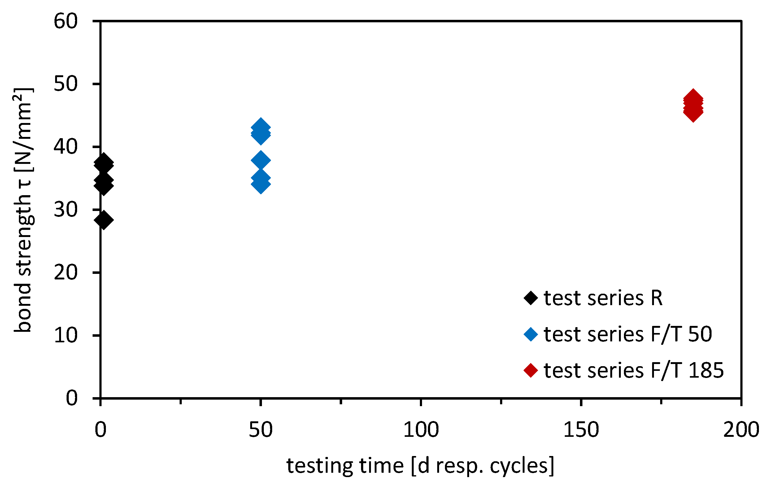
In addition, reference tension tests with a confined test setup were performed after at least the specified curing time of the bonded anchors was achieved. These tests were not loaded constantly before the tests were carried out and can be used to determine any influence of the freeze-thaw cycles on the load-bearing capacity. The average ultimate load was determined with Fum = 77.7 kN (CV = 9.5%), with a displacement at the loss of adhesion of δFu = 1.8 mm. Figure 8 shows the determined bond strength values as a result of the measured residual loads from the different test series. It is shown explicitly that with an increasing age of the bonded anchor, the bond stresses also increase. Due to the fact that a reduction of the bond stresses does not occur, it cannot be concluded that a degradation of the material occurs due to the freeze-thaw exposure for the tested epoxy-based bonded fastener. Furthermore, it can also be observed in Figure 8 that as the curing time increases, the epoxy mortar tested shows higher bond strengths as a result of the post-curing of the adhesive mortar. It may be mentioned as a recommendation that for direct comparison it would also make sense to carry out the reference tests with the same curing time as the freeze-thaw tests at the end of the cycles.
4. Discussion
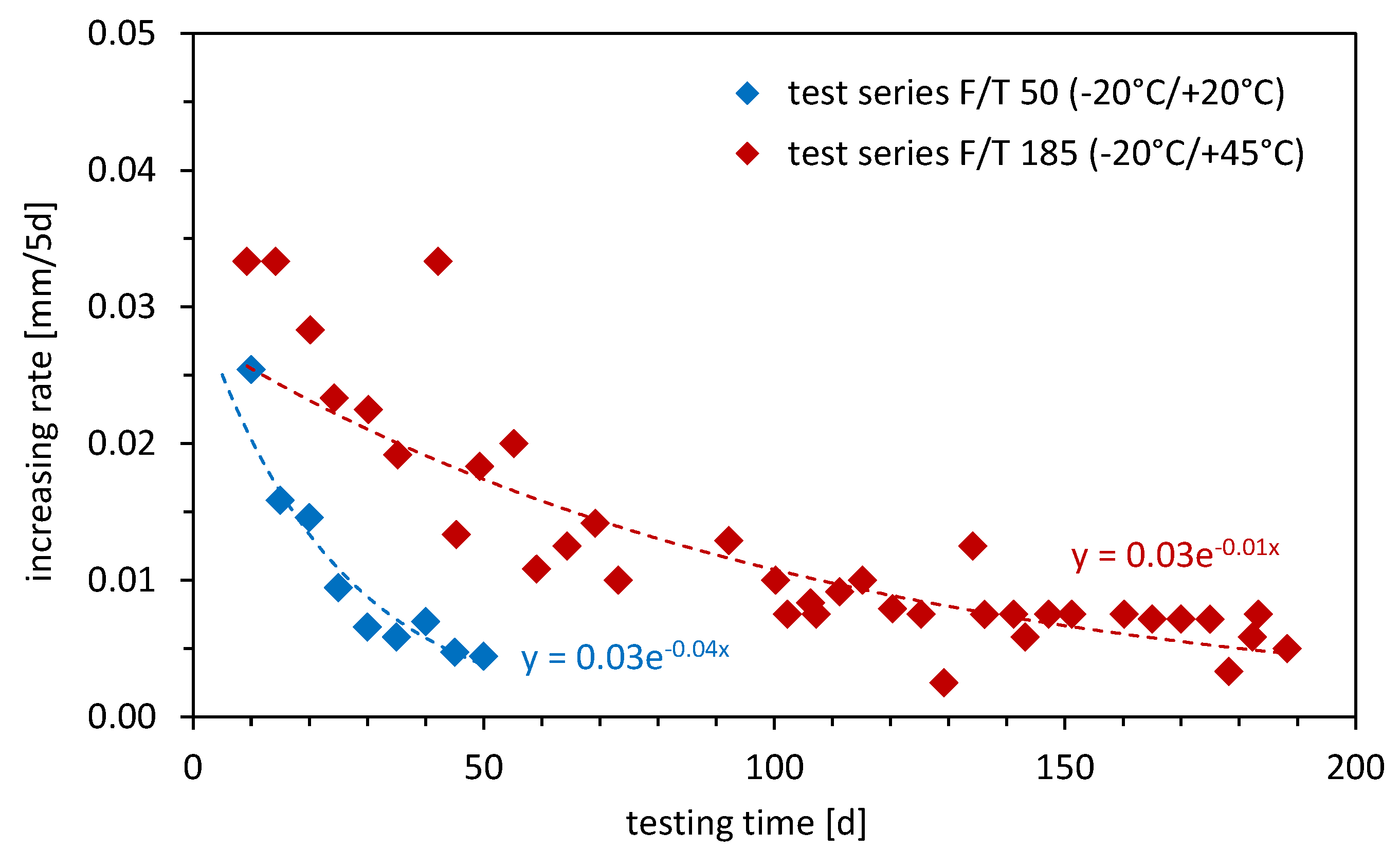
The chart of the measured displacements in Figure 7 clearly shows that in the test programme with 50 freeze-thaw cycles between −20 °C and +20 °C, a stabilisation of the displacement increase already occurs towards the end of the 50 cycles in the majority of the single tests. In contrast, the tests with the modified temperature range between −20 °C and +45 °C show, especially in the semi-logarithmic scale, that stabilisation can only be observed after approximately 150 freeze-thaw cycles. This deviation can be explained by the increased temperature difference, which has a value of 65 °C (−20 °C/+45 °C) instead of 40 °C (−20 °C/+20 °C) compared to the standard test procedure with the more partial loss of adhesive. Figure 9 clearly demonstrates the increased deformation rate. This figure shows the increase in the displacements per 5 days over the entire test duration for both test programmes. This also clearly shows that the increase in the displacements in the test programme with an adjusted temperature range between −20 °C and +45 °C first stabilises after approx. 150 freeze-thaw cycles.
5. Conclusions
In this article, the freeze-thaw test according to EAD 330499-01-0601 [3] has been analysed in detail. It is demonstrated that for a working life of 50 years and assumed constant climatic conditions, the test with a temperature range of −20 °C to +20 °C can be considered appropriate. The freeze-thaw test programme performed in accordance with the specifications of EAD 330499-01-0601 [3], with a temperature amplitude of 40 °C, provides the expected results. The measured increase in the displacements decreases with an increasing number of freeze-thaw cycles and is close to zero after 50 cycles. Additionally, the measured displacements are below the threshold of the mean value of the displacements at a loss of adhesion from the reference test without freeze-thaw cycling; if the displacement at a loss of adhesion is considered as assessment criteria equivalent to sustained load tests without temperature cycles. As with the additional findings above, the following is stated:
- (1)
- In the case of an extension of service life, the defined temperature range should be considered critically in the case of changing climatic conditions, especially if not only freeze-thaw conditions should be considered in the test programme, but also real temperature fluctuations within one year. This is based on the assumption that one cycle is interpreted as an annual cycle over the working life of a bonded fastener.
- (2)
- Considering changing climate conditions, on the basis of a real meteorological analysis, and also taking into account extreme events, an adjusted test programme was developed with a temperature range of −20 °C to +45 °C, which was generally based on the standard test procedure in the case of cycle duration and a constantly applied load. Conducting these modified tests with a temperature range of −20 °C to +45 °C keeping the same curing time, and in comparison to the standard tests, larger initial displacements at the beginning and higher rates of increase in the displacements in the further course of the 50 freeze-thaw cycles occurred.
- (3)
- In particular, it is necessary for this modified test procedure to extend the test duration until a reliable statement can be made on the asymptotic reduction of the increase in the displacements, which was 185 days for the tested bonded anchor type. It was also demonstrated that in these tests the measured displacements are below the mean value of the displacements at a loss of adhesion in the reference tests. This is basically an indication of the suitability of the used bonded anchor under these testing conditions.
- (4)
- For the tested bonded anchor system, the displacements after 50 or 185 cycles are below the displacements at a loss of adhesion determined on short-time reference tests. This could be applied as an additional assessment criterion for establishing modified testing procedures considering climate changing effects.
- (5)
- Based on the test results obtained, it can be clearly concluded that it should at least be discussed to update the requirements and regulations for freeze-thaw tests on bonded anchors in order to ensure realistic framework conditions. These should consider the real climatic conditions to be expected over the working life of a bonded fastener. As a consequence of the performed investigation, a possible update of freeze-thaw testing could move the tests from pure freeze-thaw tests towards experiments that take into account real annual temperature cycles that bonded fasteners undergo during their working life.
Author Contributions
Conceptualization, E.S. and O.Z.; methodology, E.S.; software, E.S. and O.Z.; validation, E.S. and O.Z.; formal analysis, E.S. and O.Z.; investigation, E.S. and O.Z.; resources, O.Z. and K.B.; data curation, O.Z.; writing—original draft preparation, E.S. and O.Z.; writing—review and editing, K.B.; visualization, E.S. and O.Z.; supervision, K.B. All authors have read and agreed to the published version of the manuscript.
Funding
This research received no external funding.
Institutional Review Board Statement
Not applicable.
Informed Consent Statement
Not applicable.
Data Availability Statement
All data used are provided in the contribution.
Acknowledgments
Thanks to Duro Petricevic, Florian Stocker, Philipp Köttl and Simon Reichmann for their support in the experiments.
Conflicts of Interest
The authors declare no conflict of interest.
References
- Eligehausen, R.; Mallée, R.; Silva, J.F. Anchorage in Concrete Construction, 1st ed.; Ernst & Sohn Verlag für Architektur und technische Wissenschaften GmbH & Co. KG: Berlin/Heidelberg, Germany, 2006. [Google Scholar]
- Eligehausen, R.; Appl, J.-J.; Lehr, B.; Mészároš, J.; Fuchs, W. Tragverhalten und bemessung von befestigungen mit verbunddübeln unter zugbeanspruchung—Teil 1: Einzeldübel mit großem achs- und randabstand. Beton-Stahlbetonbau 2004, 99, 561–571. [Google Scholar] [CrossRef]
- European Organisation for Technical Assessment. EAD 330499-01-0601—Bonded Fasteners for Use in Concrete; European Organisation for Technical Assessment: Brussels, Belgium, 2018. [Google Scholar]
- ICC-ES International Code Council Evaluation Service. AC308—Acceptance Criteria for Post-installed Adhesive Anchors in Concrete Elements; ICC-ES International Code Council Evaluation Service: Birmingham, AL, USA, 2016. [Google Scholar]
- ACI Committee 355. ACI 355.4-11—Qualification of Post-installed Adhesive Anchors in Concrete; American Concrete Institute: Farmington Hills, MI, USA, 2011. [Google Scholar]
- Kunz, J.; Cook, R.; Fuchs, W.; Spieth, H. Tragverhalten und bemessung von chemischen befestigungen. Beton-Stahlbetonbau 1998, 93, 15–19. [Google Scholar] [CrossRef]
- Cook, R.; Douglas, E.; Davis, T.; Liu, C. NCHRP Report 757—Long-Term Performance of Epoxy Adhesive Anchor Systems; Transportation Research Board: Washington, DC, USA, 2013; p. 279. [Google Scholar]
- Nilforoush, R.; Nilsson, M.; Söderlind, G.; Elfgren, L. Long-term performance of adhesive bonded anchors. ACI Struct. J. 2016, 113, 251–261. [Google Scholar] [CrossRef]
- Kuosa, H.; Ferreira, M.; Leivo, M. Freeze-Thaw Testing, CSLA Project—Task 1: Literature Review; VTT Technical Research Centre of Finland: Espoo, Finland, 2013; p. 41. [Google Scholar]
- Rehm, G. Zur Frage des Langzeitverhaltens von Hilti Verbundankern (HVU). Gutachterliche Stellungnahme Nr. 22/07.85, 1985.
- Spieth, H. Tragverhalten und Bemessung von Eingemörtelten Bewehrungsstäben. Ph.D. Thesis, Fakultät für Bauingenieur- und Vermessungswesen, Institut für Werkstoffe im Bauwesen der Universität Stuttgart, Stuttgart, Germany, 2002. [Google Scholar]
- Higgins, C.; Klingner, R. Effects of environmental exposure on the performance of cast-in-place and retrofit anchors in concrete. ACI Struct. J. 1998, 95, 506–515. [Google Scholar]
- Higgins, C.; Klingner, R. Effects of Environmental Cycling on the Strength of Short Retrofit Anchors Bolts; Research Report, No. 1208-1F; Center for Transportation Research—Bureau of Engineering Research, University of Texas at Austin: Austin, TX, USA, 1991; p. 206. [Google Scholar]
- Bowditch, M. The durability of adhesive joints in the presence of water. Int. J. Adhes. Adhes. 1996, 16, 73–79. [Google Scholar] [CrossRef]
- Hand, H.; Arah, C.; Mc Namara, D.; Mecklenburg, M. Effects of environmental exposure on adhesively bonded joints. Int. J. Adhes. Adhes. 1991, 11, 15–23. [Google Scholar] [CrossRef]
- Feng, C.; Keong, C.; Hsueh, Y.; Wang, Y.; Sue, H. Modeling of long-term creep behavior of structural epoxy adhesives. Int. J. Adhes. Adhes. 2005, 25, 427–436. [Google Scholar] [CrossRef]
- El Menoufy, A. Creep Behaviour of Post-Installed Adhesive Anchors under Various Sustained Load Levels and Environmental Exposures. Master’s Thesis, University of Waterloo, Waterloo, ON, Canada, 2010. [Google Scholar]
- El Menoufy, A.; Soudki, K. Effects of various environmental exposures and sustained load levels on the service life of postinstalled adhesive anchors. J. Mater. Civ. Eng. 2014, 26, 863–871. [Google Scholar] [CrossRef]
- Zhang, K.; Zhou, J.; Yin, Z. Experimental study on mechanical properties and pore structure deterioration of concrete under freeze–thaw cycles. Materials 2021, 14, 6568. [Google Scholar] [CrossRef] [PubMed]
- Dong, F.; Wang, H.; Yu, J.; Liu, K.; Guo, Z.; Duan, X.; Qiong, X. Effect of freeze–thaw cycling on mechanical properties of polyethylene fiber and steel fiber reinforced concrete. Constr. Build. Mater. 2021, 295, 123427. [Google Scholar] [CrossRef]
- Pilehvar, S.; Szczotok, A.M.; Rodríguez, J.F.; Valentini, L.; Lanzón, M.; Pamies, R.; Kjøniksen, A.-L. Effect of freeze-thaw cycles on the mechanical behavior of geopolymer concrete and Portland cement concrete containing micro-encapsulated phase change materials. Constr. Build. Mater. 2018, 200, 94–103. [Google Scholar] [CrossRef]
- Harmanci, Y.E.; Michels, J.; Chatzi, E. Behaviour of Prestressed CFRP Anchorages during and after Freeze-Thaw Cycle Exposure. Polymers 2018, 10, 565. [Google Scholar] [CrossRef] [PubMed] [Green Version]
- Pan, Y.; Xian, G.; Li, H. Effects of Freeze-Thaw Cycles on the Behavior of the Bond between CFRP Plates and Concrete Substrates. J. Compos. Constr. 2018, 22, 04018011. [Google Scholar] [CrossRef]
- ZAMG, Klimatologisches Jahrbuch, ZAMG Zentralanstalt für Meteorologie und Geodynamik. Available online: www.zamg.ac.at (accessed on 4 October 2020).
- Becsi, B.; Laminghofer, J. ClimaMap Climate Indizes: Karten Niederösterreich/Wien, Version 2, Wien, Österreich. 2018. Available online: https://hdl.handle.net/20.500.11756/2b237d25 (accessed on 5 October 2020).
- Kerestes, Z. Lokalklimatische Untersuchungen in Wien. Master’s Thesis, University of Natural Resources and Life Sciences, Vienna, Austria, 2016. [Google Scholar]
- Stierschneider, E.; Tamparopoulos, A.; McBride, K.; Bergmeister, K. Influencing factors on creep displacement assessment of bonded fasteners in concrete. Eng. Struct. 2021, 241, 112448. [Google Scholar] [CrossRef]
Figure 1.
Schematic temperature cycles of freeze-thaw tests in accordance to the regulations provided in EAD 330499-01-0601, Section 2.2.2.7 [3].
Figure 1.
Schematic temperature cycles of freeze-thaw tests in accordance to the regulations provided in EAD 330499-01-0601, Section 2.2.2.7 [3].

Figure 2.
Overview of the air temperature values of the daily mean averages; values are taken from [24].
Figure 2.
Overview of the air temperature values of the daily mean averages; values are taken from [24].

Figure 3.
Overview of the number of days of freeze-thaw cycles per year in accordance to the values taken from [24].
Figure 3.
Overview of the number of days of freeze-thaw cycles per year in accordance to the values taken from [24].

Figure 4.
Schematic temperature cycles of freeze-thaw tests for the modified testing procedure.

Figure 5.
Schematic description of the approach, considering the real climate conditions for freeze-thaw testing.
Figure 5.
Schematic description of the approach, considering the real climate conditions for freeze-thaw testing.

Figure 6.
Used test setup in the climate chamber for the freeze-thaw condition tests.

Figure 7.
(a) Measured displacements during the 50 freeze-thaw cycles between −20 °C and +20 °C (blue lines) and during the 185 freeze-thaw cycles between −20 °C and +45 °C (red lines); (b) measured displacements in a semi-logarithmic scale of the testing time.
Figure 7.
(a) Measured displacements during the 50 freeze-thaw cycles between −20 °C and +20 °C (blue lines) and during the 185 freeze-thaw cycles between −20 °C and +45 °C (red lines); (b) measured displacements in a semi-logarithmic scale of the testing time.


Figure 8.
Determined bond strength values τ as a result of the measured residual load capacities in the different test series.
Figure 8.
Determined bond strength values τ as a result of the measured residual load capacities in the different test series.

Figure 9.
Development of increasing rate of the measured displacements per 5 days in the freeze-thaw tests for different testing protocols.
Figure 9.
Development of increasing rate of the measured displacements per 5 days in the freeze-thaw tests for different testing protocols.


Table 1.
Overview of the performed test programme under freeze-thaw conditions.
| Test Series | Description | Size | hef [mm] | Temperature Range | No. of Cycles | No. of Tests | Nsust [kN] | Age Residual Load Test [d] |
|---|---|---|---|---|---|---|---|---|
| F/T 50 | Freeze-thaw tests acc. to EAD 330499-01-0601 | M12 | 60 | −20 °C/ +20 °C | 50 | 6 | 17.6 | 50 |
| F/T 185 | Freeze-thaw tests acc. to modified testing programme | M12 | 60 | −20 °C/ +45 °C | 185 *) | 6 | 17.6 | 185 |
| R | Reference tests | M12 | 60 | +20 °C | - | 6 | - | 1 |
*) Result of the observation of the increasing rate of the displacements.
Table 2.
Test results of the freeze-thaw tests with 50 cycles, 185 cycles and the reference tests.
| Bonded Anchor M12 hef = 60 mm | F/T 50 50 Freeze-Thaw Cycles −20 °C/+20 °C | F/T 185 185 Freeze-Thaw Cycles −20 °C/+45 °C | R Reference Tests +20 °C | |||||
|---|---|---|---|---|---|---|---|---|
| Discussed in | Section 3.2 | Section 3.3 | Section 3.4 | |||||
| Parameter | δ50cycl. | Fu | δFu | δ185cycl. | Fu | δFu | Fu | δFu |
| Test no. | [mm] | [kN] | [mm] | [mm] | [kN] | [mm] | [kN] | [mm] |
| #1 | 0.32 | 95.43 | 1.68 | 1.07 | 107.93 | 2.24 | 64.17 | 1.63 |
| #2 | 0.74 | 77.07 | 1.93 | 1.39 | 102.87 | 2.39 | 83.68 | 1.97 |
| #3 | 0.98 | 79.31 | 1.42 | 1.67 | 104.46 | 2.78 | 78.55 | 1.79 |
| #4 | 0.37 | 94.60 | 1.88 | 0.88 | 107.24 | 3.42 | 76.40 | 2.06 |
| #5 | 0.83 | 97.45 | 2.17 | 1.36 | 103.36 | 2.25 | 84.91 | 1.66 |
| #6 | 0.91 | 85.66 | 2.12 | 1.41 | 106.15 | 3.29 | 78.54 | 1.92 |
| Mean Value | 0.7 | 88.3 | 1.8 | 1.3 | 105.3 | 2.7 | 77.7 | 1.8 |
| Standard Deviation | 0.3 | 8. 81 | 0.3 | 0.3 | 2.1 | 0.5 | 7.4 | 0.2 |
| CV [–] | 0.41 | 0.10 | 0.15 | 0.21 | 0.02 | 0.19 | 0.10 | 0.09 |
| τ [n/mm2] | - | 39.0 | - | - | 46.6 | - | 34.5 | - |
Publisher’s Note: MDPI stays neutral with regard to jurisdictional claims in published maps and institutional affiliations. |
© 2022 by the authors. Licensee MDPI, Basel, Switzerland. This article is an open access article distributed under the terms and conditions of the Creative Commons Attribution (CC BY) license (https://creativecommons.org/licenses/by/4.0/).
Share and Cite
MDPI and ACS Style
Stierschneider, E.; Zeman, O.; Bergmeister, K. Freeze-Thaw Behaviour of Post-Installed Bonded Anchors under Changing Climate Conditions. CivilEng 2022, 3, 332-346. https://0-doi-org.brum.beds.ac.uk/10.3390/civileng3020020
AMA Style
Stierschneider E, Zeman O, Bergmeister K. Freeze-Thaw Behaviour of Post-Installed Bonded Anchors under Changing Climate Conditions. CivilEng. 2022; 3(2):332-346. https://0-doi-org.brum.beds.ac.uk/10.3390/civileng3020020
Chicago/Turabian StyleStierschneider, Elisabeth, Oliver Zeman, and Konrad Bergmeister. 2022. "Freeze-Thaw Behaviour of Post-Installed Bonded Anchors under Changing Climate Conditions" CivilEng 3, no. 2: 332-346. https://0-doi-org.brum.beds.ac.uk/10.3390/civileng3020020