Article

Coupled Thermal-Hydraulic Analysis and Species Mass Transport in a Versatile Experimental Salt Irradiation Loop (VESIL) Using CTF

1
Department of Mechanical, Aerospace, and Nuclear Engineering, Rensselaer Polytechnic Institute, 110 8th St, Troy, NY 12180, USA
2
Idaho National Laboratory, 1955 N Fremont Ave, Idaho Falls, ID 83415, USA
3
Oak Ridge National Laboratory, 5200, 1 Bethel Valley Rd, Oak Ridge, TN 37830, USA
*
Author to whom correspondence should be addressed.
J. Nucl. Eng. 2021, 2(3), 309-317; https://0-doi-org.brum.beds.ac.uk/10.3390/jne2030025
Submission received: 2 October 2020 / Revised: 11 August 2021 / Accepted: 12 August 2021 / Published: 24 August 2021
(This article belongs to the Special Issue Selected Papers from PHYSOR 2020)

Abstract

:
With the resurgence of interest in molten salt reactors, there is a need for new experiments and modeling capabilities to characterize the unique phenomena present in this fluid fuel system. A Versatile Experimental Salt Irradiation Loop (VESIL) is currently under investigation at Idaho National Laboratory to be placed in the Advanced Test Reactor (ATR). One of the key phenomena this proposed experiment plans to elucidate is fission product speciation in the fuel-salt and the subsequent effects this has on the fuel-salt properties, source term generation, and corrosion control. Specifically, noble gases (Xe & Kr) will bubble out to a plenum or off-gas system, and noble metals (Mo, Tc, Te, etc.) will precipitate and deposit in specific zones in the loop. This work extends the mass transfer and species interaction models in CTF (Coolant-Boiling in Rod Arrays—Two Fluids) and applies these models to give a preliminary estimation of fission product behavior in the proposed VESIL design. A noble metal–helium bubble mass transfer model is coupled with the thermal-hydraulic results from CTF to determine the effectiveness of this insoluble fission product (IFP) extraction method for VESIL. Amounts of IFP species extracted to the off-gas system and species distributions in VESIL after a 60-day ATR cycle are reported.

1. Introduction

The Versatile Experimental Salt Irradiation Loop (VESIL) shown below in Figure 1a, is a proposed fuel-bearing integrated effect experiment currently under investigation at Idaho National Laboratory (INL) [1]. This natural circulation molten salt loop would contain a fuel-bearing salt and is envisaged to be irradiated in one of the I-positions of the Advanced Test Reactor (ATR). As the fuel-salt is irradiated, the process of insoluble fission product (IFP) species migration, accumulation, and deposition will occur during the 60-day ATR cycle. Specifically, a noble metal (NM) particle deposition and noble gas (NG) bubble formation may become significant and be used as an online experimental indicator of the burnup process.
This work applies the species mass transport capabilities currently under development within the subchannel thermal-hydraulics code CTF [2]. It acts as a feasibility study of the salt-loop in light of these complex transport phenomena. A previously developed NM deposition model [3] and helium bubbling model [4] are coupled to determine what species will be extracted in an off-gas system. Figure 1b illustrates the combined interaction of NM deposition and extraction via circulating helium bubble swarms.

Importance of IFP Transport and Resulting Effects

Most liquid-fueled MSR concepts are based on the Molten Salt Reactor Experiment (MSRE) where the uranium is dissolved in the salt and is pumped through a loop or integral design. This key feature means that fission products will directly populate in the liquid fuel-salt during burnup and are free to migrate and mix in the reactor, rather than be held mostly stationary in a solid fuel pellet. A majority of the fission products are soluble in the fuel-salt. However, NM and NG fission products are typically insoluble in the fuel-salt and form solid particulates and gaseous bubbles [5].
These insoluble species will have sink and source effects due to concentration-driven diffusion across material and phase boundaries in the reactor. Therefore, these insoluble species’ time and spatial dependence must be tracked and predicted to determine mass accountancy, few-group cross-section constants of the fuel-salt in the reactor core, corrosion rates, and source term generation. Additionally, the cumulative decay heat from these IFPs could be significant and localized enough to cause structural damage in the reactor without active cooling [6].

2. Materials and Methods

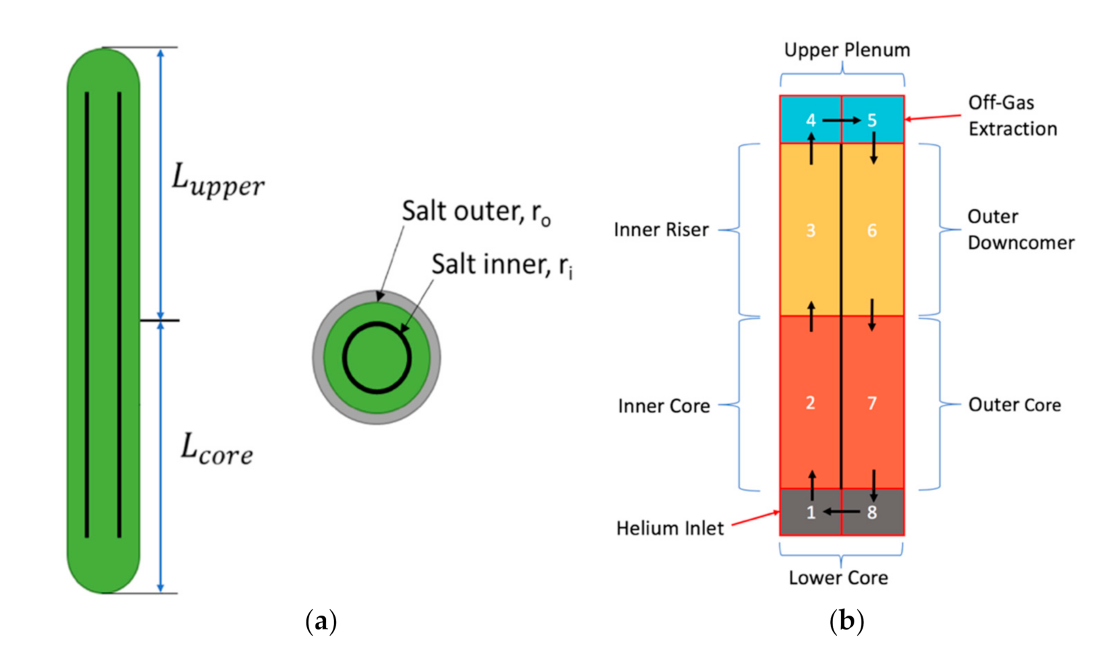
2.1. VESIL Design & Parameters

The current VESIL design was chosen after several thermal-hydraulic analyses conducted at INL using STAR-CCM+ and SAM [7]. The selected design is a natural circulation-driven loop shown below in Figure 2a, where half of the loop (Lcore) is exposed to the neutron flux, and the other half (Lupper) is outside the core, experiencing no flux. Shown in Figure 2b is the CTF VESIL geometry. The salt heats up and rises through the inner core in cells 1–4 and cools down, flowing through the outer annulus in cells 5–8.
When using the helium bubbling model to extract IFPs, the helium bubbles are introduced at the bottom of the loop in cell 1 and flow concurrently with the fuel-salt until they reach the liquid-gas interface in cell 5 where they are extracted to the off-gas system. The key parameters of the loop calculated previously by SAM/STAR-CCM+ are summarized in Table 1 below [7]. The CTF model is then forced to agree with the SAM/STAR-CCM+ results to ensure the correct natural circulation velocity and temperature.
The helium bubbling parameters are listed in Table 2, where the amount of helium bubbles extracted at the upper plenum to the off-gas system is characterized by an extraction efficiency [4]. The proposed fuel-salt is UCl3-NaCl based on the REBUS-3700 concept, and the thermal-physical properties of the salt for the temperature range listed in Table 1 are summarized below in Table 3, where only the density is temperature dependent [8].

2.2. Noble Metal Deposition Model Review & Assumptions

The NM deposition model is a thin film model where a mass transfer coefficient K captures the combined effect of advection and diffusion. The transfer is driven by a concentration difference across the film [3]. Starting from the left-hand side in Equation (1), the terms include source term change in mass density with respect to time, the mass transfer coefficient K multiplied by the surface area available for deposition divided by the control volume multiplied by the difference in the mass density in the bulk control volume and the equilibrium mass density that exists in the liquid at the solid-liquid interface or deposition surface. As can be seen, the surface area to volume ratio is an important geometrical factor in NM deposition.
S d e p o s i t i o n = K A s u r f V c e l l ( ρ b u l k ρ i n t e r f a c e )
The first assumption made is the value of the ρ i n t e r f a c e term, the equilibrium mass density of the species that exists in the liquid. Since NMs acted lyophobically in FLiBe salt in the MSRE, all NMs in the fuel-salt can be assumed to be completely insoluble, and therefore, the equilibrium mass density of the species that exist in the liquid is zero— ρ i n t e r f a c e = 0 [9]. This simplification is strongly dependent on the assumption that the redox of the fuel-salt (the fluorine/chlorine potential) is well controlled.
Lastly, the diffusion coefficients of these species, or species diffusivities, in the UCl3-NaCl molten fuel-salt is not entirely known. However, an estimated value taken from the MSRE is applied to all of the NM species in the model [9]. Although this value was derived for species in FLiBe salt, compared with recent experiments carried out in molten MgCl2-KCl-NaCl, the value used in this analysis is well within the tight range of diffusivities measured [10]. The diffusion coefficients in UCl3-NaCl may likely be slightly different, but considering the overlap of diffusivities of metal species in FliBe and MgCl2-KCl-NaCl salts, this difference should be negligible for this analysis. The diffusion coefficient D is then used to determine the mass transfer coefficient K from the mass transfer Dittus-Boelter correlation for turbulent flows shown in Equation (2) below [9], where d is the hydraulic diameter of the pipe or flow conduit, ρ d v μ is the dimensionless Reynolds number, and μ ρ D is the dimensionless Schmidt number, leaving K with units of length per time (e.g., m/s).
K = 0.023 D d ( ρ d v μ ) 0.8 ( μ ρ D ) 0.4             0.6 S c 160                 R e D h > 10 , 000

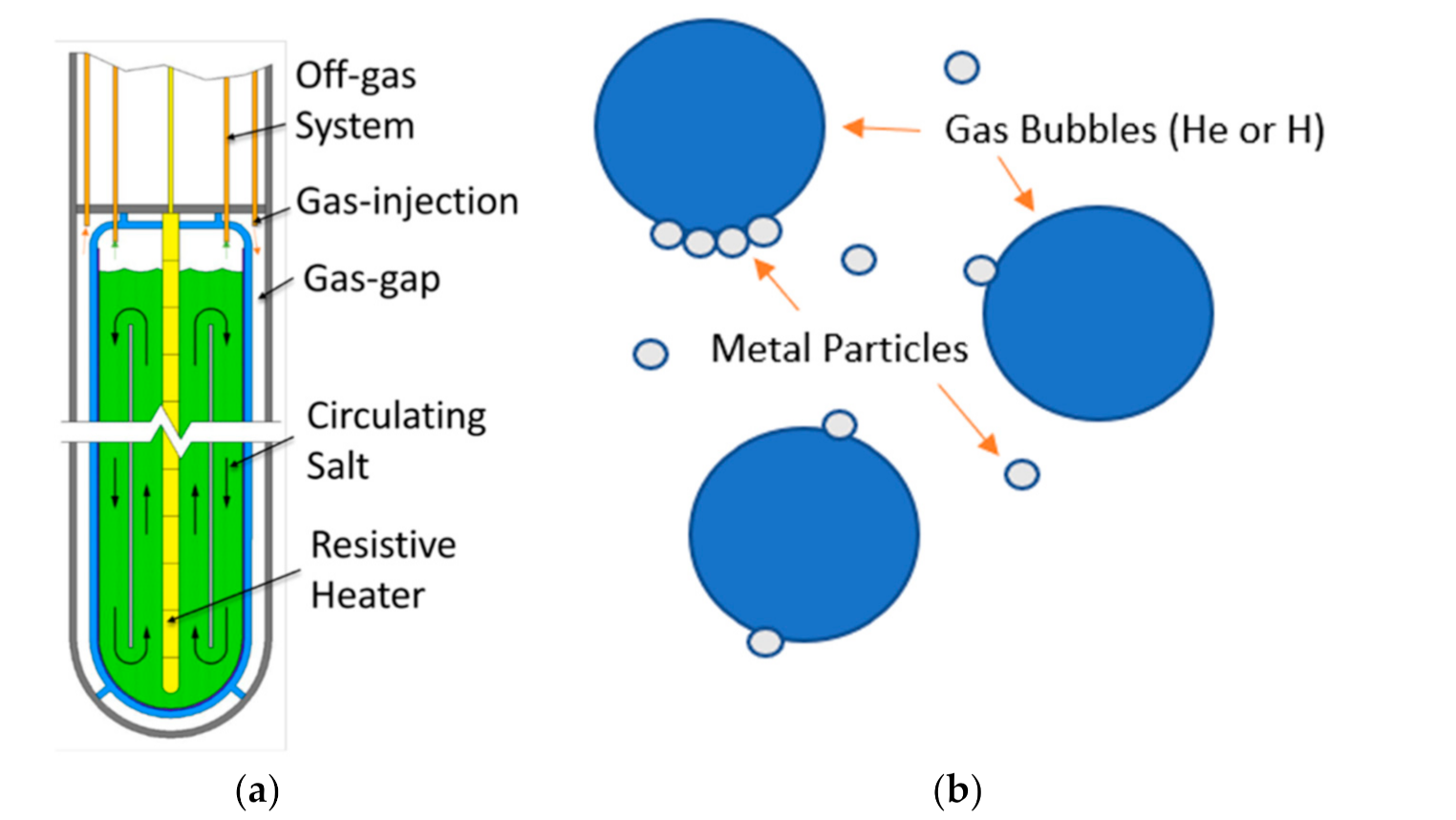
2.3. Helium Bubbling Model Review & Assumptions

The helium gas bubbling model is a homogenous equilibrium two-phase flow model where the number of helium bubbles is determined by the gas inlet flow rate, the ideal gas law, and set initial bubble diameter. Assuming no phasic slip between the bubbles and the bulk liquid flow, the bubbles are then transported in CTF as a species around the loop by the fuel-salt velocity field [4]. It is important to determine the interfacial area made by the helium bubble swarm to calculate the correct surface area for species mass transfer to the bubbles.
The ideal gas law is used to determine the changing diameter of the bubbles due to changes in pressure, mass, volume, and temperature traveling through the loop. Here the bubbles are assumed to be in thermal equilibrium with the fuel-salt, small and spherically shaped, and that the void fraction is sufficiently small to avoid bubble-bubble interactions.
P b = P l + 4 σ l d
The Young–Laplace Equation is used to calculate the pressure inside the gas bubble due to the pressure outside the bubble and surface tension shown in Equation (3) above, assuming the bubble is roughly static in the fuel-salt [4]. Here, P b is the pressure inside the bubble, P l is the pressure of the surrounding liquid, σ l is the surface tension of the bubble, and d is the bubble diameter. Inserting Equation (3) back into the ideal gas law, and assuming spherical bubbles in thermal equilibrium with the fuel-salt, results in Equation (4), where n is the number of moles of gas in a single bubble, R is the ideal gas constant, and T l is the temperature of the surrounding liquid. This nonlinear equation is then solved via Newtons method to determine the bubble diameter in each cell of the loop, which is then used to calculate the total helium bubble interfacial area available for mass transfer in that cell location [4].
[ P l + 4 σ l d ] π d 3 6 = n R T l
The coupling of the species mass transport/mass transfer model with the thermal-hydraulic results taken from CTF is clearly seen in Equation (4), where the bubble interfacial area available for mass transfer directly depends upon the temperature and pressure calculated by CTF in each cell. Here n, the number of moles in each bubble is calculated by dividing the total moles of gas in the cell by the total number of bubbles calculated from the CTF bubble species transport solver at the previous time step [4].
Lastly, the extraction boundary condition for the helium bubbles carrying any deposited species to the off-gas system must be determined. For simplicity, a bubble removal efficiency at the removal location in cell 5 of Figure 2b is defined. Here a percentage of the bubble mass flow rate is extracted as seen previously in Table 2. Future work will incorporate buoyancy and diffusion forces to determine the mass transfer of bubbles across the liquid-gas interface in cell 5 or consider the effect of a baffle to accurately determine and control the bubble extraction rate.

2.4. Noble Metal Helium Bubble Coupling & Off-Gas Mass Accounting Methodology
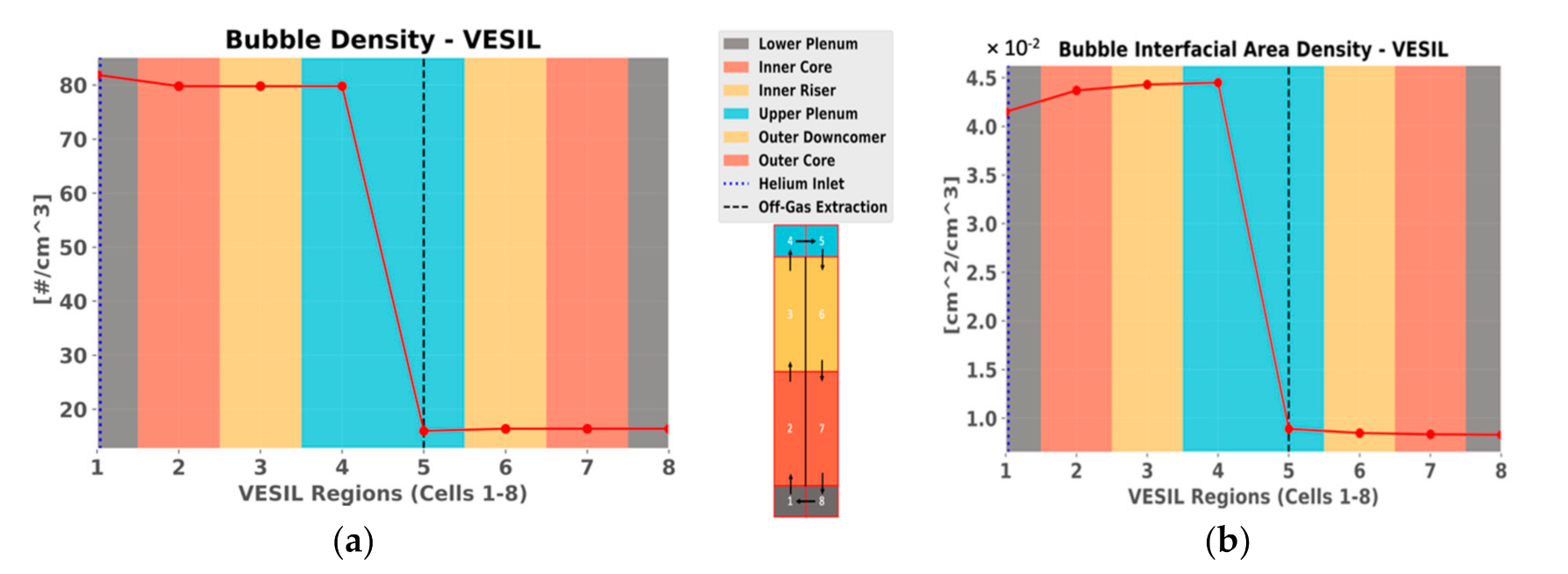
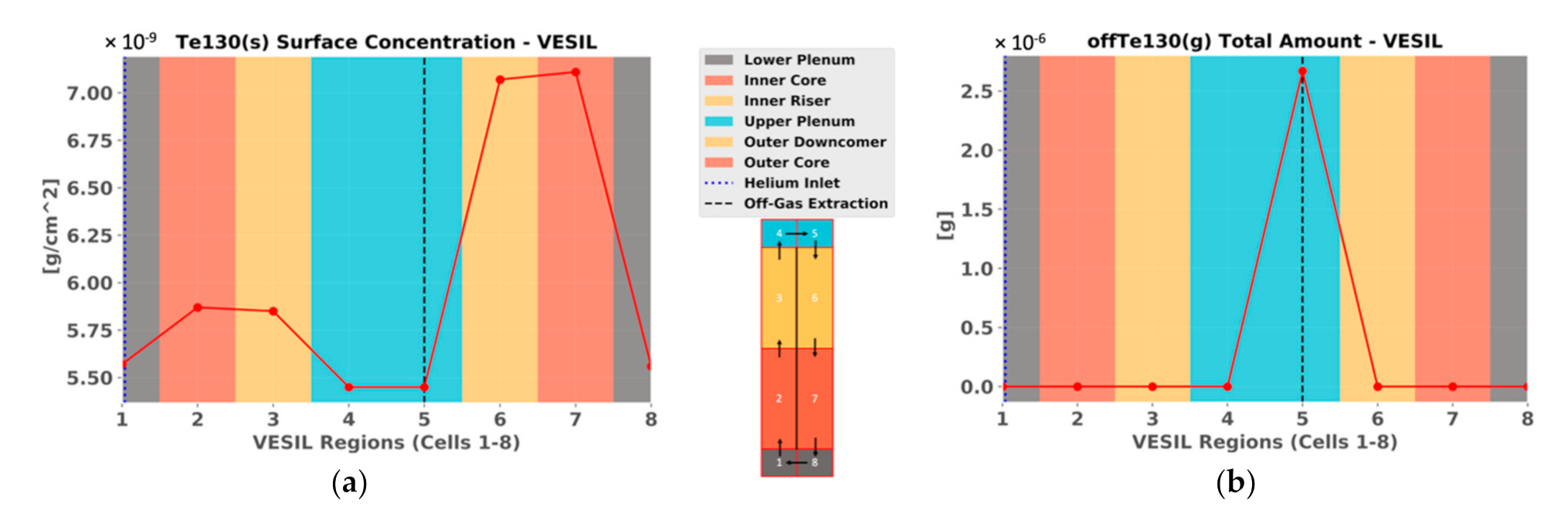
It is important to note that many off-gas isotope species (which are primarily xenon) have NM precursors as seen in the decay chain Sn–Sb–Te–I–Xe, where the color red indicates insoluble solid species, the color green indicates a soluble liquid species, and the color blue indicates an insoluble gas species.
Therefore, as xenon isotopes are extracted via mass transfer into the helium bubbles, there are additional NM particulates that will also attach to the helium bubble and are hypothesized to be extracted into the off-gas system or at least the liquid-gas interface at the top of the loop via flotation, as seen in Figure 1b [9]. This NM deposition on the circulating helium bubbles acts to increase the overall off-gas extraction.
Each isotope species is fragmented into several different “sub” species in order to track the concentration of a given species in different locations (e.g., 132Sn(l)—species in the bulk liquid, 132Sn(s)—species on the VESIL wall, 132Sn(g)—species attached to helium bubbles, 132Sn(Og)—species in the off-gas system) [3]. All species are born from fission in the bulk liquid location denoted by (l), and all subsequent species grow from the loss of the bulk liquid species through mass transfer mechanisms discussed earlier. Only growth from fission, radioactive decay, and mass transfer mechanisms are currently incorporated, but neutron absorption and other effects will be incorporated in the future.

3. Results

The following five decay chains 128–132Sn–128–132Sb–128–132Te–128–132I–128–132Xe are explicitly tracked to determine the total stable xenon concentration distribution that accumulates in VESIL during the 60-day ATR cycle irradiation. The helium gas bubbling model is active with the parameters shown previously in Table 2. After 60 days of irradiation, the steady-state amounts of Sn and Sb in VESIL were insignificant due to their short half-lives ranging from seconds to minutes. However, Te and I species were significant and approached their steady-state distributions in VESIL with half-lives in the order of days.
Selective results are shown to help elucidate the overall species transport behavior in VESIL. The helium bubbling model is shown in Figure 3a,b where the bubble inlet is in cell 1 at the center lower plenum, and bubble extraction is at cell 5 at the top of the upper plenum where the species are extracted across the liquid-gas interface to the off-gas system. The bubble interfacial area increased slightly in cells 2, 3, and 4 in Figure 3b as the bubbles rise upwards due to expanding bubble diameters from decreasing pressure and increasing temperature at the top of VESIL.
The effect of helium bubble bubbling on NM deposition is shown in Figure 4a,b. Examining the 130Te(s) surface concentration, there was heavy NM deposition occurring in cells 6 and 7 due to the high surface area of this annular region seen in Figure 2b. Additionally, deposition occurred on the walls in cells 2 and 3, but it was suppressed due to the additional bubble interfacial area in this region available for deposition, as seen in Figure 3b. This extraction effect can be seen more clearly with the significant amount of 130Te(g) extracted to the off-gas system seen in Figure 4b. After converting the surface concentrations in Figure 4a and comparing the total amount of 130Te in VESIL, it is found that 11.38% of all 130Te has been extracted to the off-gas system via helium bubbling.
It is also worth mentioning that not only does the extraction of NMs enhance off-gas extraction through preemptive capture before decay—it can also lead to significant steady-state amounts of isotopes in the off-gas system that may be unexpected. One example is 129I(l) which arrived in the off-gas system from the extraction of 129Sn(g), 129Sb(g), and 129Te(g), but also has a very long half-life ( t 1 / 2   = 1.57 × 10 7   years ). 130Te and 128Te are two other examples of long-lived species extracted into the off-gas system ( t 1 / 2   = 7.9 × 10 20   years and t 1 / 2   = 2.2 × 10 24   years respectively). With large amounts of unexpected isotopes (other than NGs xenon and krypton) building up, it is important to understand the species’ overall chemistry and atomic/molecular behavior that will accumulate in the off-gas system.
Lastly, the amount of 132Xe(g) leaving the liquid stream and depositing onto the helium bubbles is plotted in Figure 5a. A drastic growth of the amount of 132Xe(g) in the helium bubbles occurs as expected in cells 1–4, where the helium bubble interfacial area is the largest. A drastic decrease follows this in the density as the helium bubbles, and the 132Xe(g) in the helium bubbles are removed to the off-gas system in cell 5 of the upper plenum. On the other hand, the spatial distribution of soluble species like 131I(l) shown in Figure 5b is mostly dependent on the changing density of the fuel-salt due to temperature. It is important to note that this effect is small, as seen in the relative difference in the soluble I(l) concentration around the loop. A homogenous well-mixed hypothesis for such species is a reasonable assumption.
The total amounts of stable xenon gas and the amounts of stable xenon collected in the off-gas system after 60 days of irradiation are shown below in Table 4. Since VESIL would operate at a power of 94.56 kW [7], these numbers are a reasonable estimate for the amount of stable xenon buildup.

4. Discussion

As can be seen above, the helium bubbling model with its current parameters and assumptions is more than capable of extracting nearly all of the stable xenon in VESIL. This conclusion will need to be revisited when a more realistic helium bubble extraction model is used. There will likely be a significant amount of bubble recirculation depending on the bubble size and bubble concentration, reducing the amount of NGs extracted.
Ultimately, with such minimal amounts of stable xenon building up, there is no need to actively bubble the fuel-salt with helium to extract the xenon. It is very unlikely that the pressure buildup will become prohibitive from an experiment design standpoint. However, the ability to actively extract IFPs throughout the experiment to measure burnup, validate mass transfer correlations, measure corrosion rates, and determine chemical equilibriums will likely be invaluable.
Future work will investigate rudimentary redox control models to analyze the various options possible to implement within VESIL. These include gas bubbling with hydrogen, dissolving a reducing metal into the salt, and controlling the U(IV)/U(III) ratio through U additions [11]. By coupling CTF with Thermochimica, which is currently underway, the redox potential of the fuel-salt can be calculated, and corrosion rates can be estimated.

5. Conclusions

Species transport inside an in-pile salt loop was investigated and quantified. The analysis was able to provide a first-order prediction of the species’ transport inside an in-pile experiment. The initial findings are very encouraging. The helium gas bubbling model, while simple to implement, was shown to be very successful in extracting the majority of xenon and significant amount of NMs in the VESIL system. Additional analysis and sensitivity tests on the full 60-day ATR runs are currently being processed. The noble metal helium bubbling model in CTF is behaving as expected and can account for the primary mass transfer mechanisms in MSR systems. Future work will further develop this coupling and incorporate more robust physical models to determine the underlying phenomena behind NM micro-particle and NG micro-bubble agglomeration and their behavior in molten salts.

Author Contributions

Conceptualization, S.A.W., A.A.-J. and W.J.; methodology, S.A.W., Z.T. and W.J.; software, S.A.W., Z.T. and R.K.S.; validation, S.A.W. and Z.T.; formal analysis, S.A.W., A.A.-J. and W.J.; investigation, S.A.W., A.A.-J. and W.J.; resources, A.A.-J., W.J. and R.K.S.; data curation, S.A.W.; writing—original draft preparation, S.A.W.; writing—review and editing, S.A.W., A.A.-J., W.J. and R.K.S.; visualization, S.A.W. and Z.T.; supervision, A.A.-J. and W.J.; project administration, A.A.-J. and W.J.; funding acquisition, A.A.-J., S.A.W. and W.J. All authors have read and agreed to the published version of the manuscript.

Funding

This material is based upon work supported under an Integrated University Program Graduate Fellowship. This manuscript was co-authored by Battelle Energy Alliance, LLC under Contract No. DE-AC07-05ID14517 with the U.S. Department of Energy (DOE). The U.S. Government retains and the publisher, by accepting the article for publication, acknowledges that the U.S. Governement retains a nonexclusive, paid-up, irrevocable, worldwide license to publish or reproduce the published form of this manuscript, or allow others to do so, for U.S. Government purposes. The research work was partially funded through Idaho National Laboratory (INL)’s LDRD program, project number 18P38-004FP, entitled “Feasibility Assessment of a Molten Salt Loop in the ATR”, under the DOE Idaho Operations Office.

Data Availability Statement

Data available upon request.

Conflicts of Interest

The authors declare no conflict of interest. The funders had no role in the design of the study; in the collection, analyses, or interpretation of data; in the writing of the manuscript, or in the decision to publish the results.

References

  1. Abou-Jaoude, A.; Palmer, J.; Sterbentz, J.; Calderoni, P. Evaluation of a Versatile Experimental Salt Irradiation Loop (VESIL) inside the Advanced Test Reactor. In INL/EXT-19-52917; Idaho National Laboratory: Idaho Falls, ID, USA, 2019. [Google Scholar]
  2. Taylor, Z.; Salko, R.; Collins, B. Implementation of General Species Transport Capability into VERA-CS for Molten Salt Reactor Analysis. In Proceedings of the 2018 ANS Annual Meeting, Philadelphia, PA, USA, 17–21 June 2018; Volume 118, pp. 1061–1064. [Google Scholar]
  3. Walker, S.A.; Taylor, Z.; Salko, R.; Collins, B.; Ji, W. Noble Metal Mass Transport Model for Molten Salt Reactor Analysis in VERA-CS. In Proceedings of the M&C 2019, Portland, OR, USA, 25–29 August 2019; pp. 2268–2277. [Google Scholar]
  4. Taylor, Z. Implementation of Multi-Phase Species Transport into VERA-CS for Molten Salt Reactor Analysis. Master’s Thesis, University of Tennessee Knoxville, Knoxville, TN, USA, 2019. [Google Scholar]
  5. Compere, E.L.; Bohlmann, E.G.; Kirslis, S.S.; Blankenship, F.F.; Grimes, W.R. Fission Product Behavior in the Molten Salt Reactor Experiment. In ORNL-4865; Oak Ridge National Laboratory: Oak Ridge, TN, USA, 1975. [Google Scholar]
  6. Carter, W.L. Decay Heat Generation by Fission Products and 233Pa in a Single-Region Molten Salt Reactor. In ORNL-CF-68-3-38; Oak Ridge National Laboratory: Oak Ridge, TN, USA, 1968. [Google Scholar]
  7. Bhaskar, S.; Abou-Jaoude, A. Preliminary Design Evaluation of a Natural Circulation Molten Salt Irradiation Loop. In Proceedings of the 2019 ANS Winter Meeting, Washington, DC, USA, 17–21 November 2019; Volume 121, pp. 1895–1896. [Google Scholar]
  8. Mourogov, A.; Bokov, P. Potentialities of the fast spectrum molten salt reactor concept: REBUS-3700. Energy Convers. Manag. 2006, 47, 2761–2771. [Google Scholar] [CrossRef]
  9. Kedl, R.J. The Migration of a Class of Fission Products (Noble Metals) in the Molten-Salt Reactor Experiment. In ORNL-TM-3884; Oak Ridge National Laboratory: Oak Ridge, TN, USA, 1972. [Google Scholar]
  10. Yang, Q.; Ge, J.; Zhang, J. Electrochemical Study on the Kinetic Properties of Fe2+/Fe, Ni2+/Ni, Cr2+/Cr and Cr3+/Cr in Molten MgCl2-KCl-NaCl Salts. Electrochem. Soc. 2021, 168, 012504. [Google Scholar] [CrossRef]
  11. Zhang, J.; Forsberg, C.W.; Simpson, M.F.; Guo, S.; Lamb, S.T.; Scarlat, R.O.; Carotti, F.; Chan, K.J.; Singh, P.M.; Doniger, W.; et al. Redox potential control in molten salt systems for corrosion mitigation. Corros. Sci. 2018, 144, 44–53. [Google Scholar] [CrossRef]
Figure 1. (a) Preliminary VESIL Design—Reproduced with permission from [1] Abou-Jaoude, A.; Palmer, J.; Sterbentz, J.; Calderoni, P. Evaluation of a Versatile Experimental Salt Irradiation Loop (VESIL) inside the Advanced Test Reactor. In INL/EXT-19-52917; Idaho National Laboratory: Idaho Falls, ID, USA, 2019; (b) Noble Metal Flotation via Bubbles.
Jne 02 00025 g001
Figure 2. (a) Simple layout of VESIL; (b) CTF VESIL representation.
Jne 02 00025 g002
Figure 3. (a) Bubble density (#/cm3); (b) Bubble interfacial area density (cm2/cm3 or cm−1).
Jne 02 00025 g003
Figure 4. (a) 130Te(s) Wall Concentration (g/cm3); (b) 130Te(g) in Off-Gas System (g).
Jne 02 00025 g004
Figure 5. (a) 132Xe(g) in He bubble (g/cm3); (b) 131I(l) in fuel-salt (g/cm3).
Jne 02 00025 g005
Table 1. VESIL parameters [7].
ParameterValue (Units)
Maximum Temperature 1011.87 (K)
Minimum Temperature910.35 (K)
∆T101.52 (K)
Fission Power Density in Core100.00 (W/cm3)
Salt Velocity0.226 (m/s)
Total Height78.00 (cm)
Height of Core39.00 (cm)
Outer Salt Radius2.778 (cm)
Inner Salt Radius1.964 (cm)
Salt Mass6.513 (kg)
Table 2. Helium bubbling parameters [4].
ParameterValue (Units)
He injection rate2.0 × 10−6 (moles/s)
Initial Bubble Diameter: Dref0.3175 (mm)
Removal Efficiency80.0 (%)
Table 3. UCl3-NaCl fuel-salt properties [8].
PropertyValue (Units)
Density (ρ)3860.4 − 0.837 × T (K) (kg/m3)
Dynamic Viscosity (µ)0.00217 (kg/m-s)
Thermal Conductivity (kT)0.7 (W/m-K)
Specific Heat Capacity (Cp)950 (J/kg-K)
Prandtl Number (Pr)2.9450
Table 4. Stable xenon accumulations after 1 ATR Cycle.
Total Stable XenonStable Xenon in Off-GasPercentage (%)
132Xe5.56 mg5.54 mg99.68%
131Xe1.63 mg1.62 mg99.43%
130Xe8.90 × 10−2 mg8.87 × 10−2 mg99.67%
129Xe1.80 × 10−13 mg1.79 × 10−13 mg99.88%
128Xe6.15 × 10−4 mg6.13 × 10−4 mg99.68%
Total Xe7.28 mg7.25 mg99.63%
Publisher’s Note: MDPI stays neutral with regard to jurisdictional claims in published maps and institutional affiliations.

