
Electro Synthesis and Characterization of PANI and PANI/ZnO Composites Films †

1
Centre de Recherche Scientifique et Technique en Analyses Physico-Chimiques, BP384, Bou-Ismail CP 42004, Tipaza, Algeria
2
Laboratoire de Chimie, Ingénierie Moléculaire et Nanostructures Université Ferhat Abbas Sétif 1, Sétif 19000, Algeria
3
Laboratoire d’Electrochimie et Matériaux, Université Ferhat Abbas Setif 1, Setif 19000, Algeria
*
Author to whom correspondence should be addressed.
†
Presented at the 24th International Electronic Conference on Synthetic Organic Chemistry,
15 November–15 December 2020; Available online: https://ecsoc-24.sciforum.net/.
Chem. Proc. 2021, 3(1), 110; https://0-doi-org.brum.beds.ac.uk/10.3390/ecsoc-24-08328
Published: 14 November 2020
(This article belongs to the Proceedings of The 24th International Electronic Conference on Synthetic Organic Chemistry)
Abstract
:The polyaniline (PANI) and ZnO doped polyaniline composite (PANI/ZnO) films were synthesized by electrochemical polymerization on transparent ITO glass substrate using cyclic voltammetry for 10th cycle by potential sweep from −200 to 900 mV vs.SCE in sulfuric acid medium with aniline monomer precursor and LiClO4 supporting salt at room temperature. The doping effects of ZnO on PANI properties were studied; electrical properties of PANI and PANI/ZnO composite were estimated from Mott–Schottky analysis which demonstrated an n-type conductivity for all films with carrier concentrations in order of 1017and 1019 for PANI and PANI/ZnO composite respectively. The effect of the concentration of ZnO dopant in the electrolyte on the morphology and the composition of the PANI were investigated from scanning electron microscopy coupled Energy Dispersive Spectroscopy analysis (SEM+EDS). UV-VIS was investigated to study the optical characteristics of the films such as transmittance and band gap energy. The characteristics of the films were found to be depending on the concentration of ZnO particles in the electrolyte during electrochemical polymerization. Fourier transform infrared (FTIR) confirms the links and the interaction between PANI and ZnO dopant.
1. Introduction
The π-conjugated polymers have currently received much attention of scientists and researchers include polypyrrole, polyfurane and especially polyaniline which were investigated in the literature [1,2,3]. Because of their various potential applications in the fields of batteries, electro chromic display devices, sensors, and organic electrical devices [4,5,6,7,8,9,10]. The polyaniline is one of conjugated polymers whichhas been widely studied due to its easy synthesis and reversible acid–base chemistry in aqueous solution, good chemical and thermal stabilities, redox reversibility, its metal behavior and high electric conductivity when it was doped in acid medium [11,12,13].
In recent years, the doping of conjugated polymers with different inorganic semiconducting nanoparticles such as SnO2, TiO2 and ZnO … etc. to form composite materials has been widely studied for optoelectronic applications [14,15,16]. This doping has proven an amelioration in many properties of the composites like great enhancement in PL property of PANI/ZnO composite [17] and increasing in conductivity of polyaniline/zinc oxide or polyaniline/cadmium oxide nanocomposite compared with polyaniline [18,19,20]. Various methods and ways of syntheses were investigated to fabricate the polyaniline and the polyaniline/semiconductor composite, for example Mostefaie et al. [21] have prepared these materials by an in situ chemical oxidative method of aniline monomers in the presence of ZnO nanorods, a novel Pickering emulsion route was reported by He to preparea polyaniline/nano-ZnO composite fibers [11], the solution casting technique was utilized for preparation ofpolyaniline (PANI)/ZnO nanocomposites film in the study of Ahmed etal. and that ofSingla et al. for synthesizingpolymer/ZnO nanoparticles composite [22,23], Patil et al. have prepared thepolyaniline/ZnO (50%) nanocomposites from spin coating method on glass substrates [24,25], also the electrochemical polymerizationmethod is used more often because it is environmental friendly and presents several advantages [26]. Many current works had taken this later as synthesis method of the polymers and the composite polymer/semiconductor like PANI, PANI/TiO2, polyaniline/LiMn2O4 [3,27].
The electrical properties of the conducting polymers and composites were the clef parameters to evaluate the importance and the utility of these materials. Different techniques were utilized to investigate these characteristics (conductivity, restivity and carriers’ concentration) like hall effect measurement, four point probe, but the Mott–Schottky analysis has not been reported yet, despite its simplicity and importanceof the parameterstried from this technique like carriers concentration and flat band potential which were characteristics of organic and inorganic semiconductors.
This work involves the electrochemical polymerization of polyaniline (PANI) and the polyaniline/zinc oxide composite (PANI/ZnO) films from the aniline (ANI) monomer and Zinc oxide particles in sulfiric acid medium with LiClO4 as supporting electrolyte on ITO glass electrodes. Cyclic voltamperometry was investigated as electrochemical technique for synthesis, electrical properties of the PANI and the PANI/ZnO were extracted from Mott–Schottky analysis. On the other hand, the optical characteristics were studied using UV-VIS and FTIR spectroscopy.
2. Experiments Procedures
2.1. Materials and Instrumentation
The electrodeposition of PANI is performed in aqueous acid solutionsof H2SO4, the supporting electrolyte used was lithium perchlorate (LiClO4) which is a pure salt for analysis and soluble in organic and aqueous solutions, and because of its electrochemical stability on a large domain of potential. The ZnO 99%, a powder used as a doping semiconductor, and the monomer was aniline (An) with 99.99% purity. Distilled water was for the preparation of electrolyte solution in all stages.All the electrochemical measurements (cyclic voltammetry and Mott–Schottky analysis) were performed using a Voltalab 402 type PGZ from Radio meter Analytical, coupled with a computer equipped with a software (voltamaster 4) to select the electrochemical technique and fix the desired parameters. A three-electrodes cell was used to carry out the electrochemical experiments; a platinum wire (diameter 2 mm) was used as a working electrode for electrochemical characterization. For UV-VIS and Scanning electron microscopy (SEM) coupled, ITO coated glass electrode were used as working electrodes (area of 1 cm2), a platinum wire served as an auxiliary electrode and a saturated calomel electrode (SCE) as reference, all the potential values were referred to this electrode.
The optical transmittance measurements were performed on a Shimadzu UV-spectrophotometer UV-1800 coupled with UV Probe software which works in the range of 200 to 1100 nm. The FTIR analysis of PANI and PANI/ZnO composite were performed by Jasco-FT/IR-4200 spectrophotometer.SEM and EDX measurements were carried out with a Quanta 250 with tungsten filament from FEI Company.
2.2. Preparation of the PANI and (PANI/ZnO) Composite Film
The smoothing pretreatment of the surface Pt electrode was preceded by mechanical polishing, using emery paper down to 1200 grade and degreasing with acetone/ethanol mixture, washing with distilled water and drying. The ITO substrates were ultrasonically cleaned in methanol, acetone and distillate water for 10 min and etched in nitric acid 45% for 2 min to activate the surface of the electrode. The electro polymerization of aniline in the absence and the presence of ZnO with different concentrations (10−4, 10−3, 10−1 M) was performed in potentiodynamic conditions in a cell containing 1M H2SO4 + 0.1M LiClO4and 10−1M aniline. The polyaniline (PANI) and the composite material (PANI/ZnO) were obtained on the electrode by cyclic voltammetry (cycling) in the potential range between −0.2 and 0.9 V/SCE, at a scan rate of 10 mV/s. Before each experiment, the electrolytic solution was degassed by argon bubbling for 15 min.
3. Results and Discussion
3.1. Cyclic Voltammetry
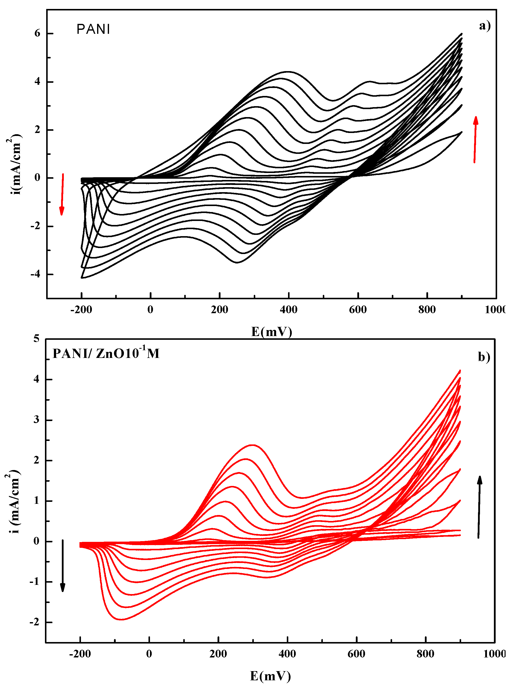
Figure 1 shows a cyclic voltammograms (CV) corresponding to the electrochemical characterization of PANI (a) and the composite material based on zinc oxide particles PANI/ZnO (b) on ITO glass substrate with 1 cm2. These voltammograms were recorded in the potential range between −0.2 and 0.9 V/SCE, and with scan rate of 10 mV s−1. On the first cycle, the cyclic voltammograms show during the positive potential scan three anodic peaks which are, respectively, observed in the potential Epa1 = 0.174, Epa2 = 0.468, and Epa3 = 0.897 V/SCE and during the negative scan potential three cathodic peaks that appear two at Epc1= −0.024, Epc2= 0.387, and Epc3= 0.553 V/SCE, which correspond to different oxidation and reduction states of the PANI. The first redox peak corresponds to the transition of the leucoemeraldine (LE) to emeraldine (EM) on the forward scan, and on the backward scan switching back to LE can be seen. The third redox peak corresponds to the transition of EM to pernigraniline (PG), while on the reversed scan the PE reduction to EM is observed. It was established that the second pair may have a different origin: it can indicate the presence of oligomers or degradation products, [28,29].
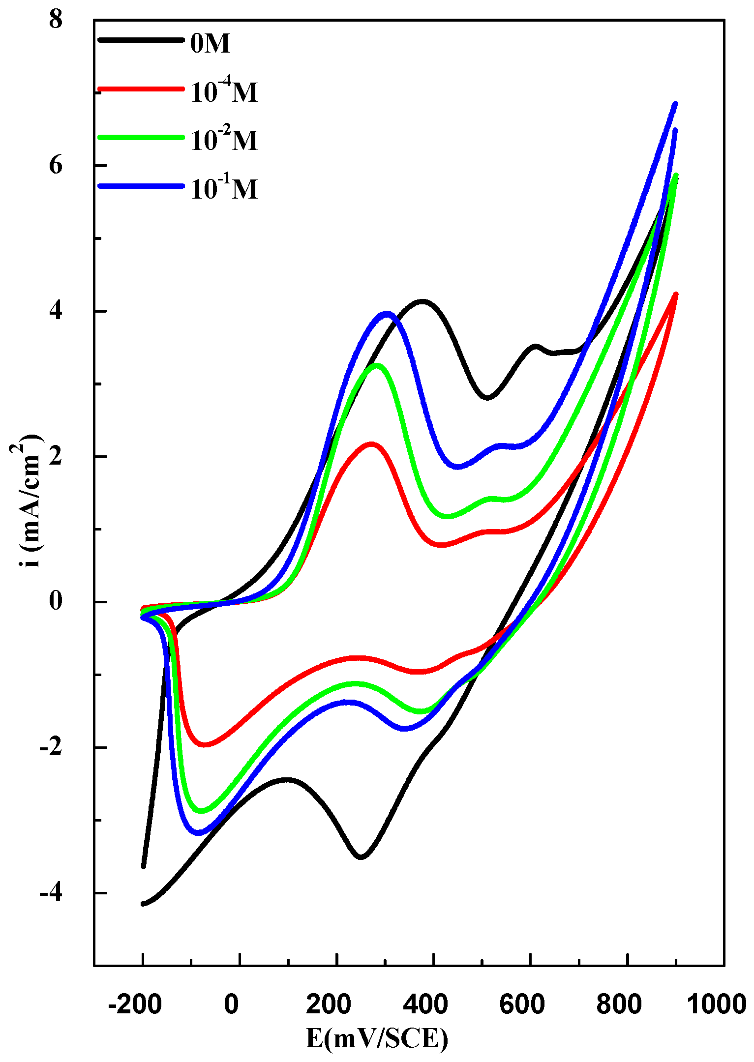
After the second cycle, the current intensity of the oxidation and reduction peaks progressively increased with the number of cycles, indicating the formation and the growth of the conducting polymer film and suggesting a systematic increase in the electrode area as a result of the actual deposition of PANI [30,31]. Comparing to the CV of the composite material PANI/ZnO with 10−1M of ZnO particle in the electrolyte, we observed a low current intensity of the redox peak, this can be due to the dispersion of ZnO nanoparticles in polymer matrix, and as consequence the decrease of active surface. The main parameter in our experiments was the effect of the dispersed ZnO concentration in the electrolyte, which varied in this extent of concentration (10−4, 10−3, 10−1M). These quantities wereadded to the solution containing the Aniline monomer. Then, we plotted the first voltamogramm for each concentration and the corresponding voltamograms are grouped in Figure 2.
As shown in Figure 2, the formation of composite PANI/ZnO, a same style ofvoltamogrammes were obtained for different concentration ZnO, but with a decrease in the current intensity of cathodic and the anodic peaks. A slight decrease was observed in the presence of 10−1 M of ZnO, but it was noticeable for 10−2 and especially for 10−4 M concentration of ZnO particles. The phenomena was accompanied by a slight shift of the cathodic peak potential towards more positive values, which can be attributed to the modification of the surface electrode by the incorporation of the ZnO particles in PANI. So dispersed ZnO influences the electrochemical deposition and properties of polyaniline.
3.2. Mott–Schottky Analysis
The Mott–Shottky analysis benefits to access at the electrical characteristics of semi-conductors like conductivity type, carrier’s concentrations and flat band potential. This technique was usedto study the comportment of semiconductor/electrolyte junction under application of bias potential and the measuring the variation of the capacitance as a function of applied potential across the space charge layer according to the Mott–Schottky equation for n type semiconductor [32,33].
where is the capacity of space charge region, εis the vacuum permittivity (ε = 8.85 × 10⁻¹⁴F cm−1), is the dielectric constant of the PANI layer (= 674.34) [34], is the carrier concentration density, is the applied potential, is flat band potential, T is the absolute temperature (T = 294 Kelven) and K is the Boltzman constant.
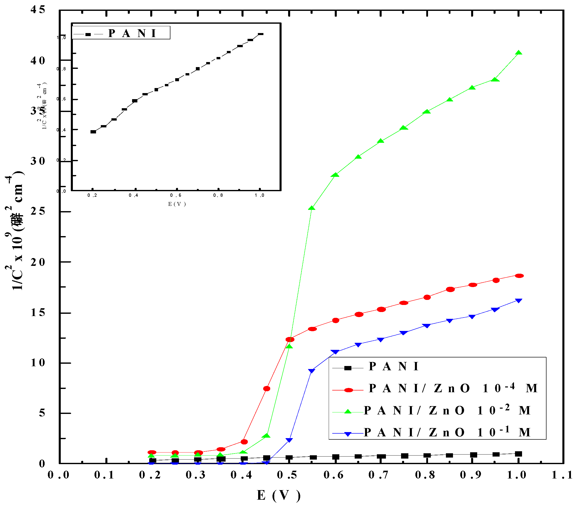
Figure 3 illustrates the Mott–Schottky plots of PANI films and PANI/ZnO composite films electropolymerized at various concentrations of ZnO particles contact in 1M H2SO4+ 0.1M LiClO4 as supporting electrolyte with 500 Hz frequency, The positive slope in these plots indicates that all the samples were a n type semiconductor [35], the estimated electron densities (N) were calculated from the slope of the Mott–Schottky plots (2/eεε. The Table 1 regroups the electron densities values as a function of concentration of ZnO particles, we can observed that the presence of ZnO particle in PANI matrix ameliorate the carrier concentration values. This later was found to depend on the ZnO concentration and was maximal for 10−1M of ZnO concentration which attainted 1.90 × 1019 cm−3. From this analysis, we can say that the doping of the PANI films with ZnO enhances the electrical conductivity (σ) which depends and proportional to the carrier concentration by the relation (2) [36]. Effectively the composite PANI/ZnO electropolymerized with 10−1 M concentration of ZnO in the electrolyte was predicted as the best conductive film.
σ = μ q ND
3.3. Scanning Electron Microscopy (SEM)
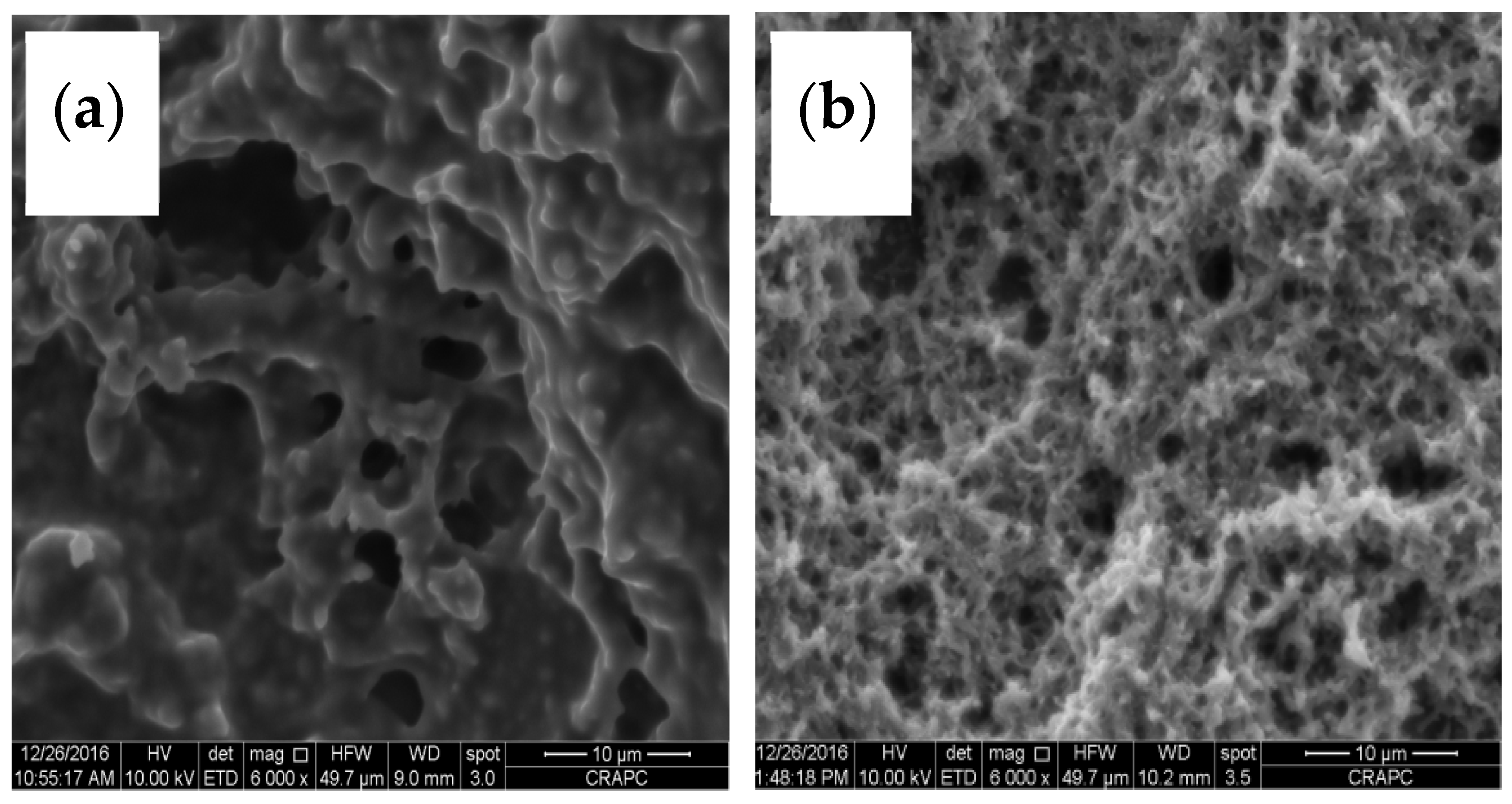
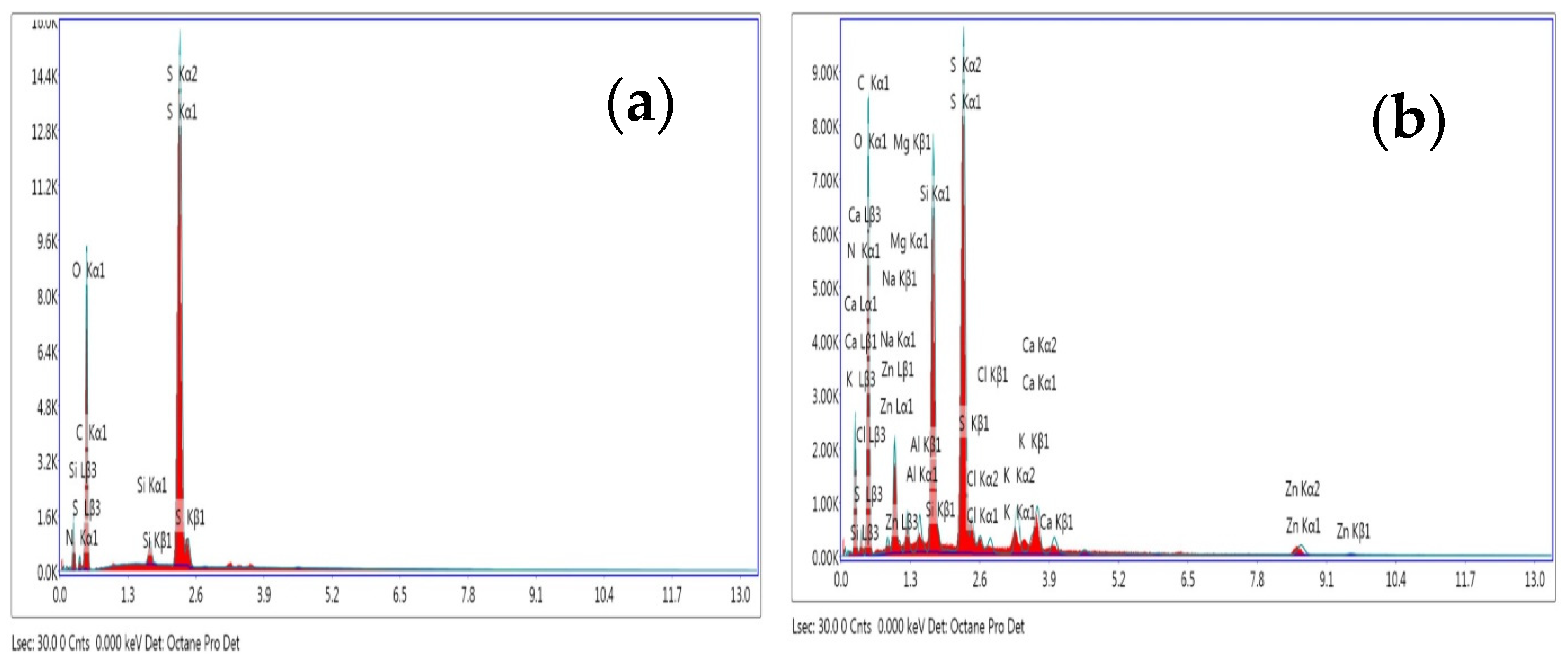
The surface morphology and elemental composition were studied through SEM coupled EDS analysis, Figure 4 presents the SEM micrographs of the PANI and PANI/ZnO composite films elaborate with 10−1 M concentration of ZnO dopant in the electrolyte. From these images, it is clear that the morphology of the PANI was changed with presence of ZnO, the PANI texture was homogenous and porous and it becomes thinner with addition of the ZnO in the electrolyte. The correspondingEDS patterns of the samples (Figure 5) show several peaks, from the patterns (a) of the PANI film the carbon (C) and nitrogen (N) signalswere characteristics of PANI polymer, sulfur(S), oxygen (Cl) and chloride signals were going from sulfuric acid and LiClO4 dopants, respectively. The existed signal of Zn element in the patterns corresponded to the PANI/ZnO10−1 M(patterns b) indicates the incorporation of the ZnO in the PANI matrix. Moreover, the composition elements of ITO coated glass substrate were shown as peaks in the EDS patterns (In, Sn, O, Ca, Si, and Mg). Table 2 and Table 3 show clearly the composition portion of these elements.
3.4. UV-VIS Study
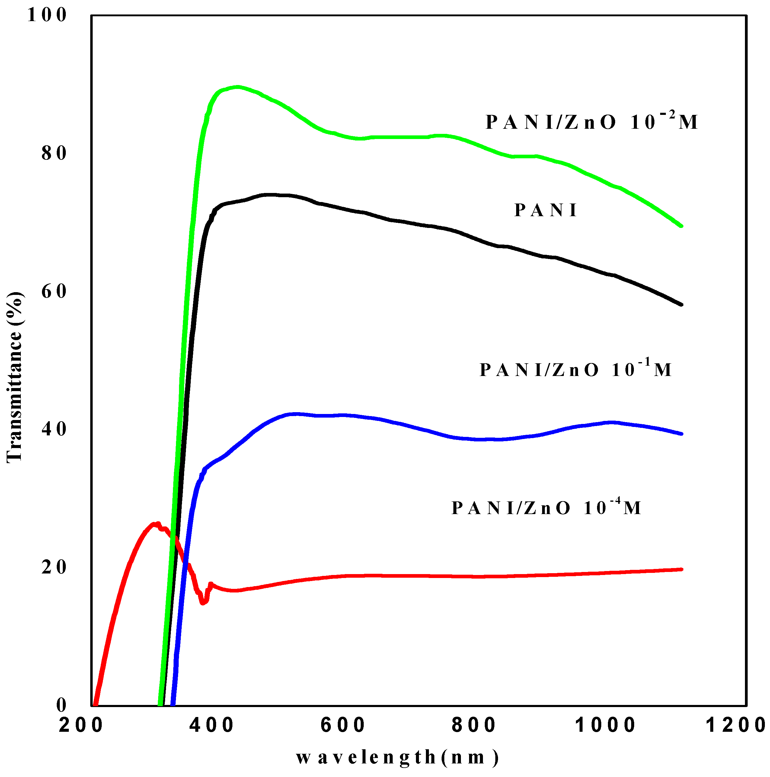
Figure 6 shows the optical transmittance spectra of PANI and PANI/ZnO composite films electropolymerized at various concentrations of ZnO particles in the electrolyte, from this figure, all the prepared PANI and PANI/ZnO composite films exhibited an optical transmittance in the visible region with a sharp fundamental absorption edge observed in UV region at around 300 nm. It can be seen that the transmittance of the films decreases from 70 to the 18 and 17 with presence of ZnO inPANI matrix for the composite PANI/ZnO 10−1M and PANI/ZnO 10−4M, respectively. However, the transmittance increases for PANI/ZnO 10−2M to attained 84%. The Tauc plots describe the dependence of the absorption coefficient and the photon energy for direct interband transitions [37] as the following equation
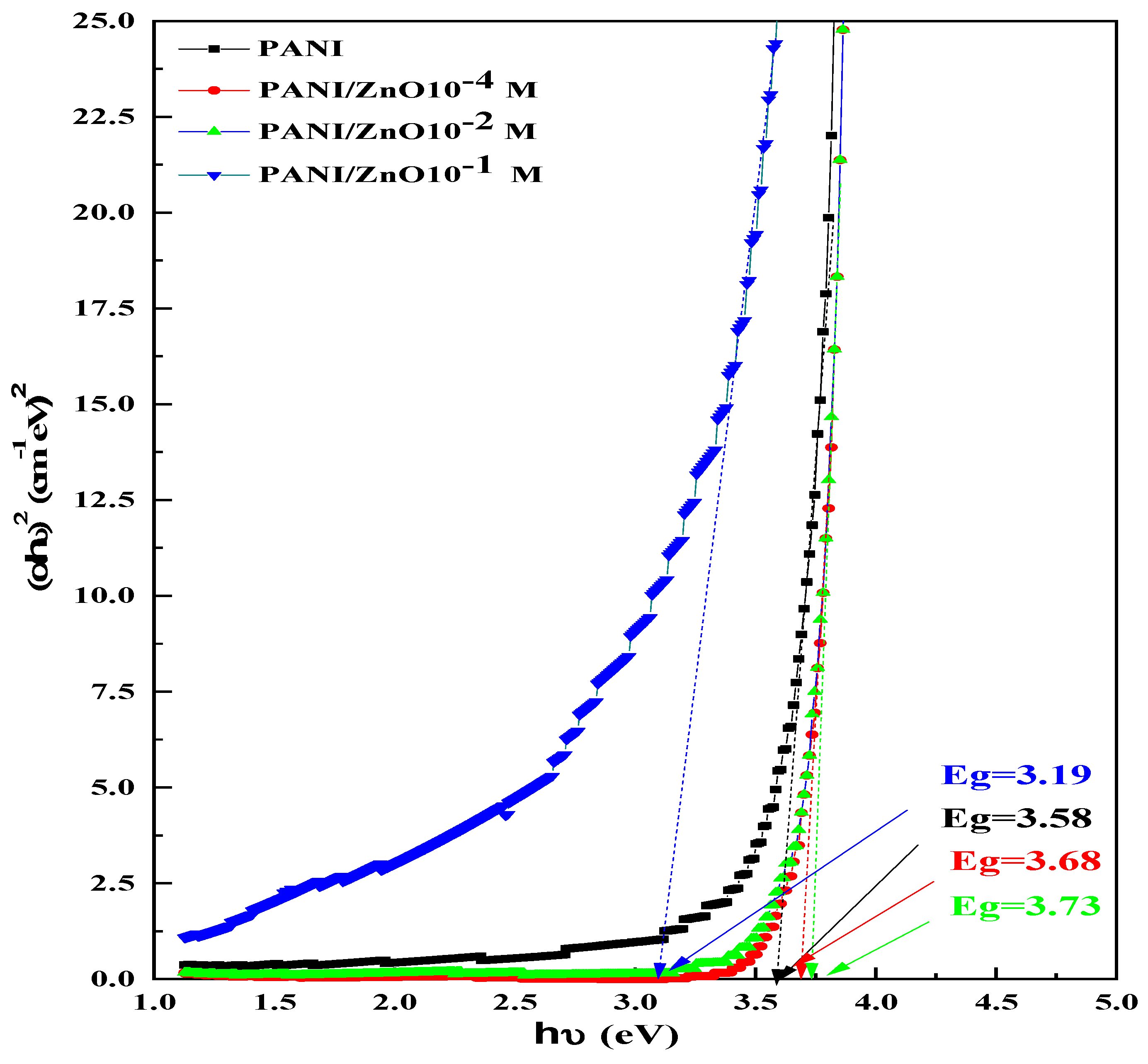
where A is a constant, α is absorption coefficient, his aPlank constant and ν is the frequency of the radiation and Eg is the band gap energy. The optical band gap energies (Eg) of PANI and PANI/ZnO composite films at various concentrations of ZnO particles were determinedfrom the extrapolatingof linear fit of (αhν)2 versushν at the αhν = 0 which shown in Figure 7. The Table 1 regroups the different values of transmittance and band gap energies corresponded to the PANI and PANI/ZnO films. It is observed that these optical characteristics were considerably influenced by the presence of different concentration of ZnO in the electrolyte.
(αhν)2 = A (hν − Eg)
3.5. FTIR Characterization
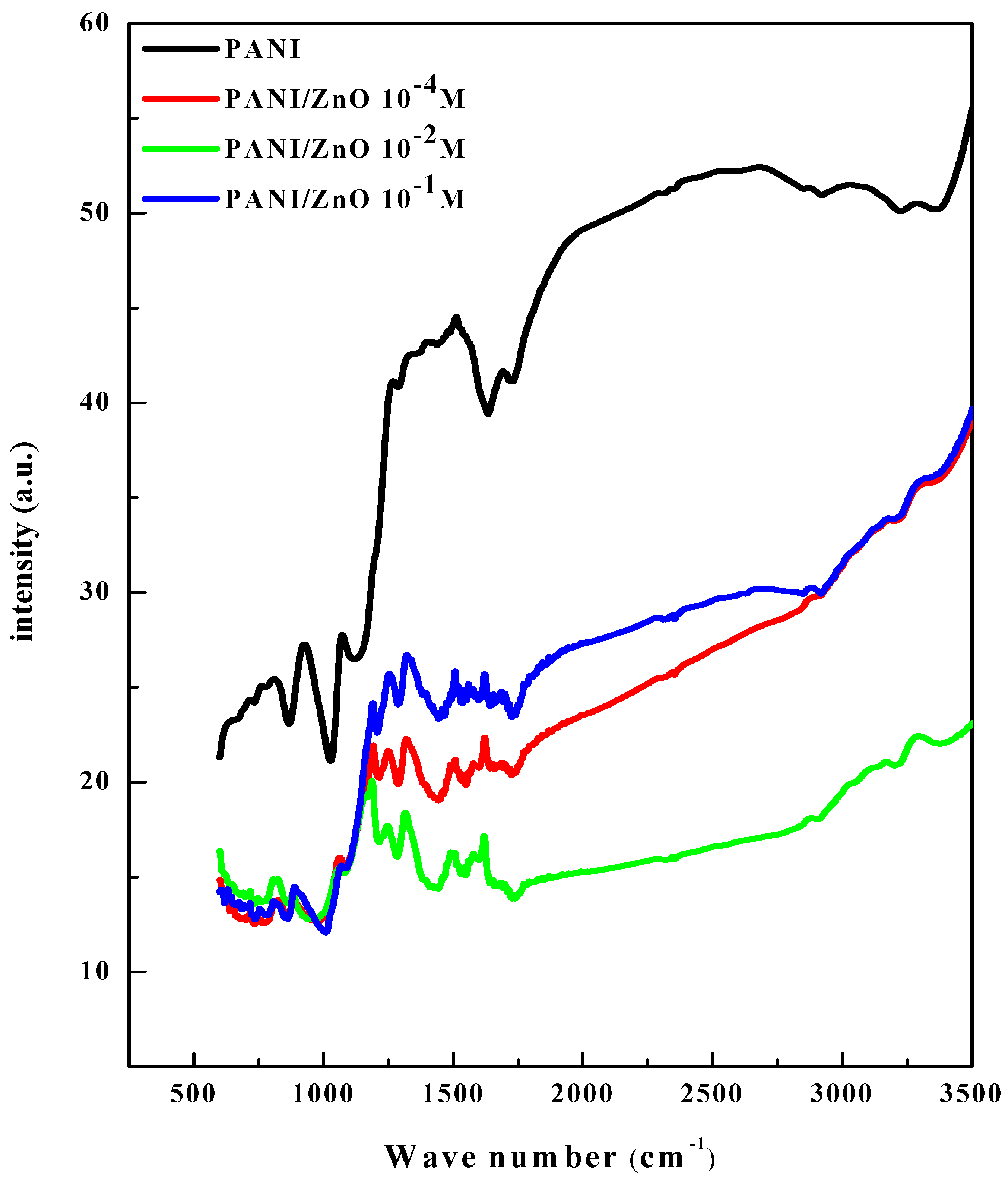
Figure 8 shows the FTIR patterns of PANI and PANI/ZnO composite films electropolymerized with different concentrations of ZnO particles in the electrolyte. In the PANI patterns the absorption peaks at 1634 and 1439 cm−1characterized as the stretching mode of vibration corresponded to the C=C and C=N links of the quinoid and benzenoid units of the PANI. The low peak at 1287 cm−1was related to the C-N stretching mode of benzenoid circle and the IR absorption bands of angular deformation out of plan of C-H bond were found at 731 and 775 cm−1 corresponded to the monosubstituted aromatic compounds presented in aniline monomer of PANI structure.For PANI/ZnO composite films with all concentration of ZnO particles, the same absorption peaks were found but with a good appearance of the peaks between 1200 to 1800 region and between cm−1578 to 882 cm−1which can be attributed to the interaction between ZnO particleand PANI by formation bonding between ZnO and N-H group of PANI. Similar results were obtained for PANI/TiO2/ZnO composite by T. J. Brooms et al. [38].
4. Conclusions
The polyaniline and polyaniline/ZnO composite films were elaborated by electrochemical polymerization using cyclic voltammetry technique on ITO substrate. Electrical properties were studied from the Mott–Schottky analysis, n-type conductivity was found for the PANI and the PANI/ZnO composite, the presence of ZnO doping in polyaniline matrix increases the carrier concentration which leading to ameliorate the electrical conductivity. The optimal concentration of ZnO particle in the electrolyte during electropolymerization was found 10−1 M which was corresponded to highest carrier concentration of 1.90 × 1019 cm−3. The ZnO doping with 10−4 and 10−1M concentration in the electrolyte has a negative effect on the optical transmittance of PANI but the ZnO doping with 10−2 M ameliorate the transmittance value to the 82.30%. The FTIR analysis confirms the links presented in the polyaniline films and the interaction between ZnO and polyaniline for the polyaniline/ZnO composite films.
Funding
This research received no external funding.
Conflicts of Interest
The authors declare no conflict of interest.
References
- Patil, S.V.; Bulakhe, R.N.; Deshmukh, P.R.; Shinde, N.M.; Lokhande, C.D. LPG sensing by p-polyaniline/n-PbS heterojunctionjunction capacitance structure. Sens. Actuators 2013, 201, 1. [Google Scholar] [CrossRef]
- Li, X.G.; Kang, Y.; Huang, M.R. Optimization of Polymerization Conditions of Furan with Aniline for Variable Conducting Polymers. J. Comb. Chem. 2006, 8, 670. [Google Scholar] [CrossRef] [PubMed]
- Harfouche, N.; Nessark, B.; Perrin, F.X. Electrochemical and surface characterization of composite material: Polyaniline/LiMn2O4. J. Electroanal. Chem. 2015, 756, 179. [Google Scholar] [CrossRef]
- Shonaike, G.O.; Advani, S.G.; Materials, A.P. Structure Property Relationships; CRS Press: Boca Raton, FL, USA, 2003. [Google Scholar]
- Hwang, J.; Son, J.I.; Shim, Y.-B. Electrochromic and electrochemical properties of 3-pyridinyl and 1,10-phenanthroline bearing poly(2,5-di(2-thienyl)-1H-pyrrole) derivatives. Sol. Energy Mater. Sol. Cells 2010, 94, 1286. [Google Scholar] [CrossRef]
- Seol, H.; Kang, D.M.; Shin, S.C.; Shim, Y.-B. Electrochemical synthesis and characterization of poly[3′-(4-formyl-3-hydroxyphenyl)-5,2′:5′,2″-terthiophene] film. Synth Met. 2006, 156, 65. [Google Scholar] [CrossRef]
- Janata, J.; Josowicz, M. Conducting polymers in electronic chemical sensors. Nat. Mater. 2003, 2, 19. [Google Scholar] [CrossRef]
- Chandra, P.; Noh, H.-B.; Shim, Y.-B. Cancer cell detection based on the interaction between an anticancer drug and cell membrane components. Chem. Commun. 2013, 49, 1900. [Google Scholar] [CrossRef]
- Babel, A.; Jenekhe, S.A. High Electron Mobility in Ladder Polymer Field-Effect Transistors. J. Am. Chem. Soc. 2003, 125, 13656. [Google Scholar] [CrossRef]
- Katz, H.E.; Bao, Z.; Gilat, S.L. Synthetic Chemistry for Ultrapure, Processable, and High-Mobility Organic Transistor Semiconductors. Acc. Chem. Res. 2001, 34, 359. [Google Scholar] [CrossRef]
- He, Y. A novel emulsion route to sub-micrometer polyaniline/nano-ZnO composite fibers. Appl. Surf. Sci. 2005, 249, 1. [Google Scholar] [CrossRef]
- Fu, Y.; Elsenbaumer, R.L. Thermochemistry and kinetics of chemical polymerization of aniline determined by solution calorimetry. Chem. Mater. 1994, 6, 671. [Google Scholar]
- Leclerk, M.; D’Aprano, G.; Zotti, G. Structure-property relationships in polyaniline derivatives. Synth. Met. 1993, 55, 1527. [Google Scholar] [CrossRef]
- Dutta, K.; De, S.K. Optical and nonlinear electrical properties of SnO2–polyaniline nanocomposites. Mater. Lett. 2007, 61, 4967. [Google Scholar] [CrossRef]
- Abaci, S.; Nessark, B.; Boukherroub, R.; Lmimouni, K. Electrosynthesis and analysis of the electrochemical properties of a composite material: Polyaniline+ titanium oxide. Thin Solid Films 2011, 519, 3596. [Google Scholar] [CrossRef]
- Goyal, S.L.; Sharma, S.; Jain, D.; Kishore, N. Study of structural, electrical and thermal properties of polyaniline/ZnO composites synthesized by in- situ polymerization. Indian J. Pure Appl. Phys. 2015, 53, 456. [Google Scholar]
- Huang, G.; Xia, H.; Shi, H.Q.; Fu, S. Controllable synthesis of novel sandwiched polyaniline/ZnO/polyaniline free-standing nanocomposite films. J. Polym. Sci. PartA Polym. Chem. 2012, 50, 2794. [Google Scholar] [CrossRef]
- Khan, A.A.; Khalid, M. Synthesis of nano-sized ZnO and polyaniline-zinc oxide composite: Characterization, stability in terms of DC electrical conductivity retention and application in ammonia vapor detection. J. App. Polym. Sci. 2010, 117, 1601. [Google Scholar] [CrossRef]
- Olad, A.; Nosrati, R. Preparation and corrosion resistance of nanostructured PVC/ZnO–polyaniline hybrid coating. Prog. Org. Coat. 2013, 76, 113. [Google Scholar] [CrossRef]
- Roy, A.S.; Anilkumar, K.R.; Prasad, M.V.N.A. Studies of AC conductivity and dielectric relaxation behavior of CdO-doped nanometric polyaniline. J. Appl. Polym. Sci. 2012, 123, 1928. [Google Scholar] [CrossRef]
- Mostafaei, A.; Zolriasatein, A. TiO2/PANI nanocomposite loaded in PVA for anticorrosive applications. Prog. Nat. Sci. Mater. Int. 2012, 22, 273. [Google Scholar] [CrossRef]
- Ahmed, F.; Kumar, S.; Arshi, N.; Anwar, M.S.; Yeon, L.S.; Kil, G.S.; Park, D.W.; Koo, B.H.; Lee, C.G. Preparation and characterizations of polyaniline (PANI)/ZnO nanocomposites film using solution casting method. Thin Solid Films 2011, 519, 8375. [Google Scholar] [CrossRef]
- Singla, M.L.; Sehrawat, R.; Rana, N.; Singh, K. Dielectric behaviour of emeraldine base polymer–ZnO nanocomposite film in the low to medium frequency. J. Nanopart Res. 2011, 13, 2109. [Google Scholar] [CrossRef]
- Patil, S.L.; Chougule, M.A.; Pawar, S.G.; Sen, S.; Patil, V.B. Effect of Camphor Sulfonic Acid Doping on Structural, Morphological, Optical and Electrical Transport Properties on Polyaniline-ZnO Nanocomposites. Soft Nanosci. Lett. 2012, 2, 46. [Google Scholar]
- Patil, S.L.; Pawar, S.G.; Chougule, M.A.; Raut, B.T.; Godse, P.R.; Sen, S.; Patil, V.B. Structural, Morphological, Optical, and Electrical Properties of PANi-ZnO Nanocomposites. Int. J. Polym. Mater. 2012, 61, 809. [Google Scholar] [CrossRef]
- de Riccardis, M.F.; Martina, V. Developments in Corrosion Protection; InTech.: Rijeka, Croatia, 2014; ISBN 978-953-51-1223-5. [Google Scholar]
- Abaci, S.; Nessark, B. Characterization and corrosion protection properties of composite material (PANI+TiO2) coatings on A304 stainless steel. J. Coat. Technol. Res. 2015, 12, 107. [Google Scholar] [CrossRef]
- Kobayashi, T.; Yoneyama, H.; Tamura, H. Influence of oxidation state, pH, and counterion on the conductivity of polyaniline. J. Electroanal. Chem. 1984, 177, 293. [Google Scholar] [CrossRef]
- Genies, E.M.; Tsintavis, C. Redox mechanism and electrochemical behaviour or polyaniline deposits. J. Electroanal. Chem. 1985, 195, 109. [Google Scholar] [CrossRef]
- Peng, C.W.; Chang, K.C.; Weng, C.J.; Lai, M.C.; Hsu, C.H.; Hsu, Y.Y.; Hung, W.I.; Wei, Y.; Yeh, J.M. Nano-casting technique to prepare polyaniline surface with biomimetic superhydrophobic structures for anticorrosion application. Electrochim. Acta 2013, 95, 192. [Google Scholar] [CrossRef]
- Hasniou, L.; Nessark, B.; Madani, A.; Lmimouni, K. Electrosynthesis and analysis of the electrochemical properties of a composite material: Polyterthiophene + titanium oxide. e-Polymers 2017, 17. [Google Scholar] [CrossRef]
- Gelderman, K.; Lee, L.; Donne, S.W. Flat-Band Potential of a Semiconductor: Using the Mott–Schottky Equation. J. Chem. Educ. 2007, 84, 685. [Google Scholar] [CrossRef]
- Daideche, K.; Azizi, A. Electrodeposition of tin oxide thin film from nitric acid solution: The role of pH. J. Mater. Sci. Mater. Electron. 2017, 28, 8051. [Google Scholar] [CrossRef]
- Verma, N.K. Effect of Zinc Oxide Nano Particle Concentration in the Polyaniline-Zinc Oxide Nanocomposite on the Dielectric Property. Mat. Sci. Res. India 2014, 11, 146. [Google Scholar] [CrossRef]
- Yun, M.; Myung, N.V.; Vasquez, R.P.; Lee, C.; Menke, E.; Penner, R.M. Electrochemically Grown Wires for Individually Addressable Sensor Arrays. Nano. Lett. 2004, 4, 419. [Google Scholar] [CrossRef]
- Abendroth, T.; Schumm, B.; Alajlan, S.A.; Almogbel, A.M.; Mäder, G.; Härtel, P.; Althues, H.; Kaskel, S. Optical and thermal properties of transparent infrared blocking antimony doped tin oxide thin films. Thin Solid Films 2017, 624, 152. [Google Scholar] [CrossRef]
- Kim, H.; Gilmore, C.M.; Piqué, A.; Horwitz, J.S.; Mattoussi, H. Electrical, optical, and structural properties of indium–tin–oxide thin films for organic light-emitting devices. J. Appl. Phys. 1999, 86, 6451. [Google Scholar] [CrossRef]
- Thabo, J.; Brooms, M.S. Onyango and AoyiOchieng. In Proceedings of the International Conference on Chemical, Integrated Waste Management & Environmental Engineering (ICCIWEE’2014), Johannesburg, South Africa, 15–16 April 2014. [Google Scholar]
Figure 1.
Electrochemical polymerization of: (a) ANI with 10 cycles, (b) ANI in presence of 10−1 M ZnO with 10 cycles, in 1M H2SO4+10–1M LiClO4+10−1M ANI with scan rate of 10 mV/s.
Figure 1.
Electrochemical polymerization of: (a) ANI with 10 cycles, (b) ANI in presence of 10−1 M ZnO with 10 cycles, in 1M H2SO4+10–1M LiClO4+10−1M ANI with scan rate of 10 mV/s.

Figure 2.
Cyclic voltammograms relating to the deposition of PANI and PANI/ZnO composite film on ITO substrate in electrolyte containing 1M H2SO4+ 0.1M Aniline + 0.1M LiClO4with different concentration ofZnO particle in electrolyteat scan rate of 10 mV/s.
Figure 2.
Cyclic voltammograms relating to the deposition of PANI and PANI/ZnO composite film on ITO substrate in electrolyte containing 1M H2SO4+ 0.1M Aniline + 0.1M LiClO4with different concentration ofZnO particle in electrolyteat scan rate of 10 mV/s.

Figure 3.
Mott–Schottky plot of PANI film and PANI/ZnO composite films electropolymerized at various concentrations of ZnO particles contact in 1M H2SO4+ 0.1M LiClO4 with 500 Hz frequency.
Figure 3.
Mott–Schottky plot of PANI film and PANI/ZnO composite films electropolymerized at various concentrations of ZnO particles contact in 1M H2SO4+ 0.1M LiClO4 with 500 Hz frequency.

Figure 4.
Scanning electron microscopy images: (a) PANI and (b) PANI/ZnO10−1 M.

Figure 5.
EDS patterns of (a) PANI, (b) PANI/ZnO 10−1 M composite films.

Figure 6.
Transmittance spectra of PANI film and PANI/ZnO composite films electropolymerized at various concentrations of ZnO particles.
Figure 6.
Transmittance spectra of PANI film and PANI/ZnO composite films electropolymerized at various concentrations of ZnO particles.

Figure 7.
Variation of (αhν)2 as function of hν of PANI film and PANI/ZnO composite filmselectropolymerized at various concentrations of ZnO particles.
Figure 7.
Variation of (αhν)2 as function of hν of PANI film and PANI/ZnO composite filmselectropolymerized at various concentrations of ZnO particles.

Figure 8.
FTIR patterns of PANI and PANI/ZnO composite electropolymerized at different concentration of ZnO particle.
Figure 8.
FTIR patterns of PANI and PANI/ZnO composite electropolymerized at different concentration of ZnO particle.


Table 1.
Variation of the carrier concentration density, transmittance and band gap energies of PANI and PANI film and PANI/ZnO composite films with ZnO concentration.
Table 1.
Variation of the carrier concentration density, transmittance and band gap energies of PANI and PANI film and PANI/ZnO composite films with ZnO concentration.
| Parameters | PANI | PANI/ZnO 10−4 M | PANI/ZnO 10−2M | PANI/ZnO 10−1 M |
|---|---|---|---|---|
| ND (cm−3) | 2.87 × 10¹⁷ | 1.80 × 10¹⁹ | 7.06 × 10¹⁸ | 1.90 × 10¹⁹ |
| Transmittance (%) | 70 | 18 | 84 | 17 |
| Eg (eV) | 3.58 | 3.68 | 3.73 | 3.19 |
Table 2.
Composition elements corresponded to the PANI film.
| Element | Weight % | Atomic % |
|---|---|---|
| C K | 20.24 | 28.36 |
| N K | 5.91 | 7.11 |
| O K | 48.74 | 51.29 |
| SiK | 0.86 | 0.51 |
| S K | 24.25 | 12.73 |
Table 3.
Composition elements corresponded to the PANI/ZnO 10−1M composite films.
| Element | Weight % | Atomic % |
|---|---|---|
| C K | 29.38 | 42.06 |
| O K | 40.97 | 44.04 |
| MgK | 0.27 | 0.19 |
| SiK | 3.30 | 2.02 |
| S K | 18.40 | 9.87 |
| ClK | 0.28 | 0.14 |
| InL | 2.45 | 0.37 |
| SnL | 0.75 | 0.11 |
| CaK | 0.60 | 0.26 |
| ZnK | 3.61 | 0.95 |
Publisher’s Note: MDPI stays neutral with regard to jurisdictional claims in published maps and institutional affiliations. |
© 2020 by the authors. Licensee MDPI, Basel, Switzerland. This article is an open access article distributed under the terms and conditions of the Creative Commons Attribution (CC BY) license (https://creativecommons.org/licenses/by/4.0/).
Share and Cite
MDPI and ACS Style
Daideche, K.; Hasniou, L.; Lerari, D. Electro Synthesis and Characterization of PANI and PANI/ZnO Composites Films. Chem. Proc. 2021, 3, 110. https://0-doi-org.brum.beds.ac.uk/10.3390/ecsoc-24-08328
AMA Style
Daideche K, Hasniou L, Lerari D. Electro Synthesis and Characterization of PANI and PANI/ZnO Composites Films. Chemistry Proceedings. 2021; 3(1):110. https://0-doi-org.brum.beds.ac.uk/10.3390/ecsoc-24-08328
Chicago/Turabian StyleDaideche, Khadidja, Leila Hasniou, and Djahida Lerari. 2021. "Electro Synthesis and Characterization of PANI and PANI/ZnO Composites Films" Chemistry Proceedings 3, no. 1: 110. https://0-doi-org.brum.beds.ac.uk/10.3390/ecsoc-24-08328