
Precision Rock Excavation: Beyond Controlled Blasting and Line Drilling


1
Department of Environment, Land and Infrastructure Engineering-DIATI, Politecnico di Torino, 10129 Torino, Italy
2
National Research Council, Geosciences and Georesources Institute-IGG, Politecnico di Torino, 10129 Torino, Italy
*
Author to whom correspondence should be addressed.
Mining 2021, 1(2), 192-210; https://0-doi-org.brum.beds.ac.uk/10.3390/mining1020013
Submission received: 29 July 2021
/
Revised: 5 September 2021
/
Accepted: 6 September 2021
/
Published: 9 September 2021
Abstract
:The strictness of the result of an excavation, whether mechanical or by means of explosives, is naturally conditioned by its objective and, therefore, by the type of technique applied to achieve it. To attain the best results in terms of rock breakage, and with respect to the final profile, it is important to evaluate the specific excavation energy and its optimization. This study, being a revision of different techniques to achieve good quality of the final walls, focuses on evaluating the effects of those techniques on the quality of the result, in both open-pit and underground operations. Different geometries and configurations can be applied to both quarrying and tunneling blasts. This study aims to push contour blasts to their limits, and the main aspects are discussed in order to improve the blast parameters in daily practice.
1. Introduction
Michelangelo is claimed to have said that sculpting is a trivial operation, as it consists only of removing the excess from a block of stone.
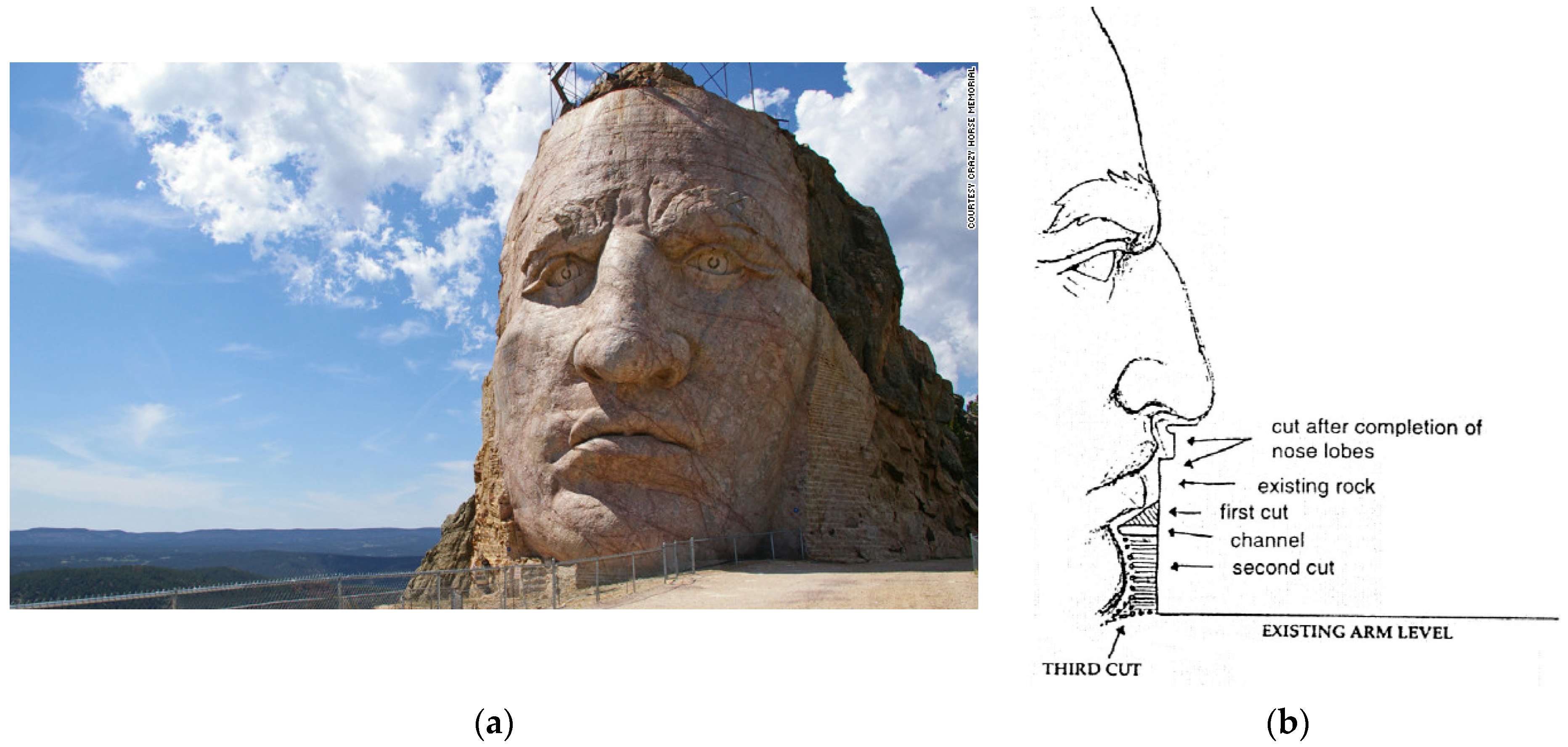
Paradoxically, the sculptor’s problem is sometimes simpler than that which is faced every day by those who carry out rock excavations requiring a very accurate outline: the added value of a statue (in particular, of one of Michelangelo’s statues) compared to the rough block is so great that it does not matter how the “excess” is removed: the sculptor could remain competitive while consuming the “excess” with a precision cutter, yet he too follows a principle of economic optimization: the first hammer blows are able to break large volumes to roughen the statue, then the strokes become more delicate, to bring out the details, and finally the manufacture is carried out by applying techniques of a higher unit cost, to remove progressively smaller volumes. The Crazy Horse project is the largest sculpture in the world, made by drill and blast—hereinafter D&B [1]—and is a spectacular example of the partnership between the arts and the engineering of explosives (Figure 1a). Every construction project has site-specific problems that need to be dealt with; these problems may be posed by the geology, location, time constraints, etc.; once they have been solved, their solutions can often be transferred to other similar construction sites. The Crazy Horse Memorial is no exception: the problem was unique and site-specific, but the solution can be used on other construction projects. To design the blast, drill patterns were conceived according to the geology of the mountain, and both downholes and horizontal holes were utilized to leave a clean wall with minimal backbreak; comprehensive blasting records were kept, including vibrations; blast dimensions; amount of rock removed; amount and type of explosives used; number, diameter, spacing, and depth of boreholes; number of delays; type of drilling; personnel needed; time taken to drill; weather; and costs.
People who work in the field of rock excavation, in order to realize such huge “sculptures” (tunnels, trenches, shafts, quarries, etc.), usually behave in a similar way. The bulk of the rock removal work, up to a given distance from the design contour, is performed at a low unit cost with ordinary production blasts, and then moves on to a much more expensive and controlled excavation—or to another technique, such as mechanical cutting—to refine the profile.
The goal of blasts (apart from cases where only the detachment effect is desired) is to transform a predetermined volume of rock on site into debris of a given grain size.
The minimum that can be expected is that the blast reduces a certain volume of rock to a transportable size, with a tolerable percentage of oversize; the maximum (“perfection”) is that it detaches and reduces all of the desired rock to fragments of a specified particle size distribution, and only at the volume that the blasting plan assigns to it, leaving a cavity with regular, stable walls and, obviously, corresponding to the designed geometry.
Coming back to the case of the sculpture, if the surface that, in the block, ideally separates the statue from the “excess” were not an ideal surface (the outline of the work, which is in the artist’s mind), but a real, physical discontinuity, the artist could simply break the crust with a few inattentive blows of the hammer to obtain the desired result.
Since there is no such surface, it must be created in advance; this is generally impossible for the sculptor, due to the complicated outline of the statue (although it is sometimes possible to apply this concept to the case of roughing, as can be seen in Figure 1b), but it is often applicable to ordinary excavations.
In this paper, the main techniques adopted to control the rock removal process (constituting a real shaping of rock, in the case of sculptures) are reviewed. Presplitting, smooth blasting, and mechanical cutting are firstly presented from a theoretical point of view. Secondly, concrete applications of these techniques are reported. The final part of the paper proposes a comparison between the techniques most commonly adopted to date. This work can represent a useful tool for both civil and mining engineers, since it reports in a compact manner the main information necessary to correctly apply the described technologies. Furthermore, the comparison between them can represent a tool able to guide the stakeholders to correctly select the best solution for a given application.
2. Excavation Technique and the Compliance with Excavation Contour
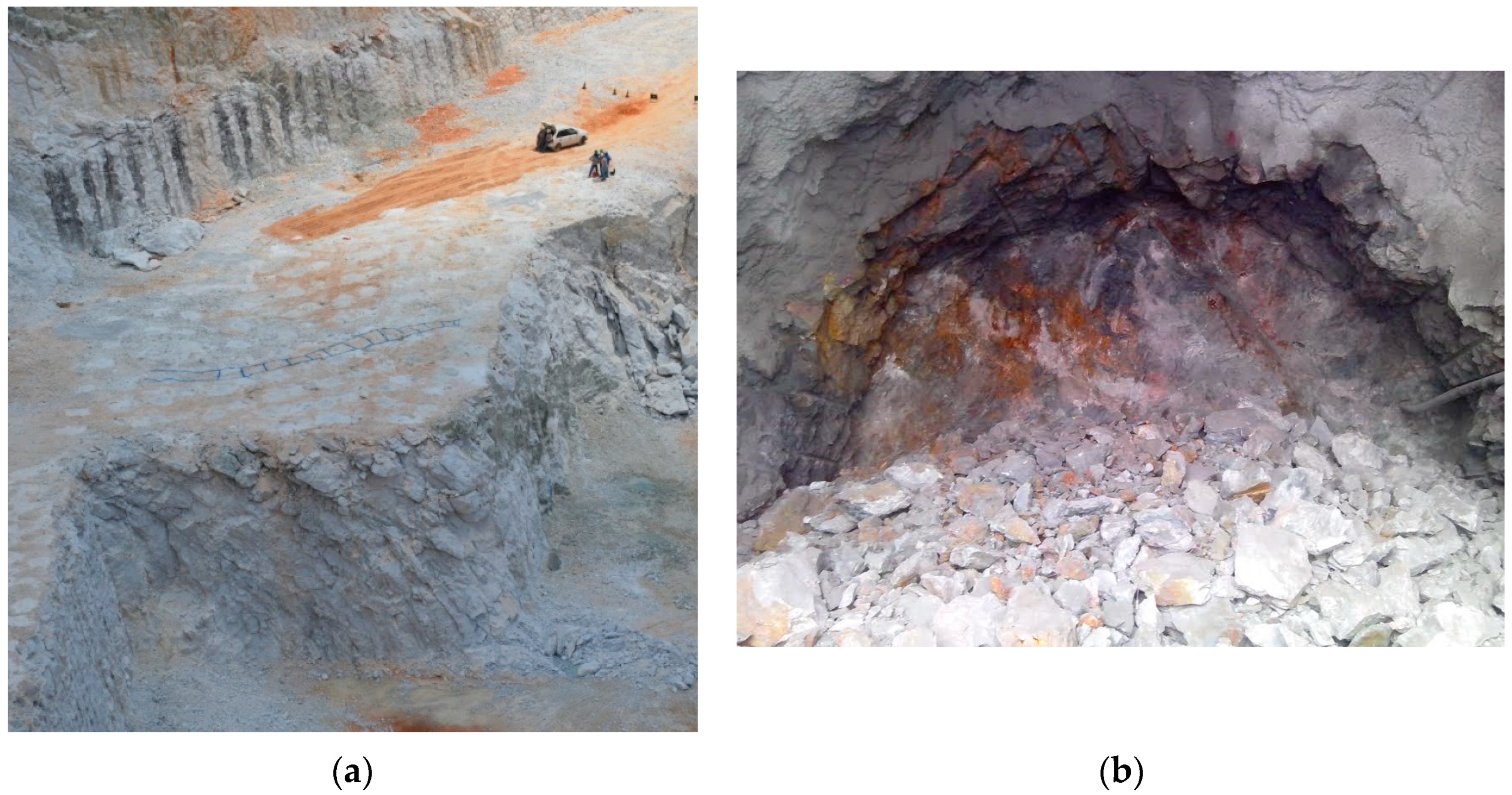
Examples of production blasts applied to two different construction sites (as far as the purpose of the job is concerned) are given in Figure 2, where an open-pit quarry for the exploitation of limestone and a round for tunnel driving are represented. The level of precision required in the two cases is obviously different: in the first, the objective is the productivity to be reached (m3/d), and no attention is generally paid to respecting a given geometry, except in the phases close to the final profile; meanwhile, in the second, the objective is to obtain a regular cavity, so that each blast must be designed in order to ensure compliance with the final contours.
In many cases, the goal is to allow the isolation of a certain volume of rock, without causing damage to the rock mass that will remain in place.
The final profile can also be made with common production blasts but, in order to reduce the extent of damage to the rock mass, techniques can be used—some through D&B, others through mechanical excavation—that allow the optimization of the result.
These techniques can be listed as follows:
- Presplitting: This technique consists of making a pre-cut in the rock mass, performed by means of explosives, to be carried out before the production blast. Table 1 shows the values commonly adopted for this operation.
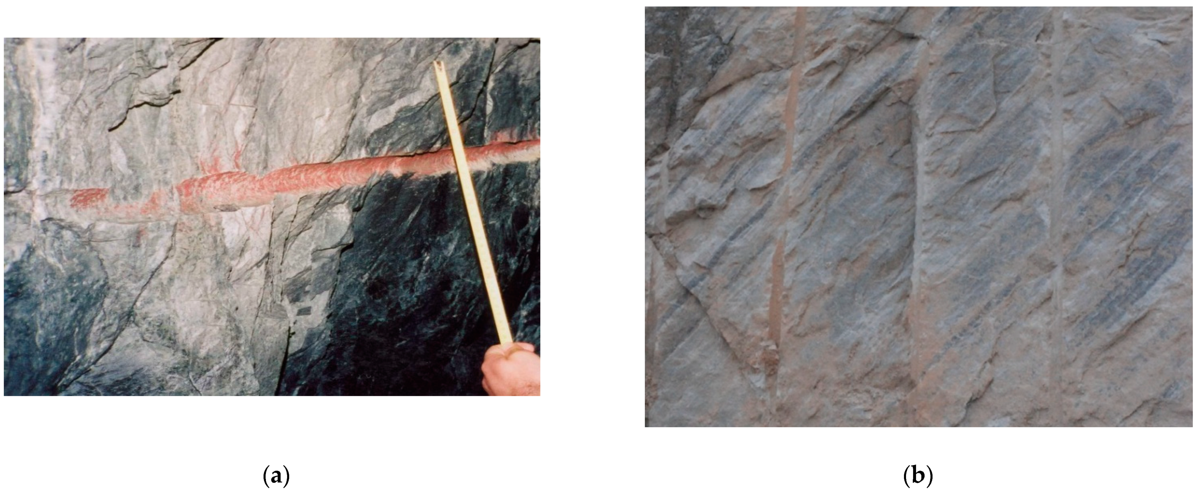
Smooth blasting: This technique, although having many similarities with presplitting, is based on the blasting of the contour holes after the production holes rather than preliminarily. Additionally, in this case, the technique is effective if the blast holes (with a diameter of 32 or 51 mm) are made with extreme precision, and if the initiation is, as far as possible, simultaneous. Since the smoothing holes must detonate last, they only have to “refine” the work and, therefore, for the purpose of sizing, these holes must be able to break down a reduced volume of rock, left over after the blasting of the last row of production holes. The calculation parameters therefore differ from those of presplitting (where the distance from the free surface parallel to the drilling surface is undefined), and it is therefore possible to increase the spacing between blast holes (reducing the specific drilling) as a result of the presence of a free surface next to the holes. Table 2 shows the parameters commonly adopted when performing smooth blasting. An example of the results obtained is given in Figure 3.
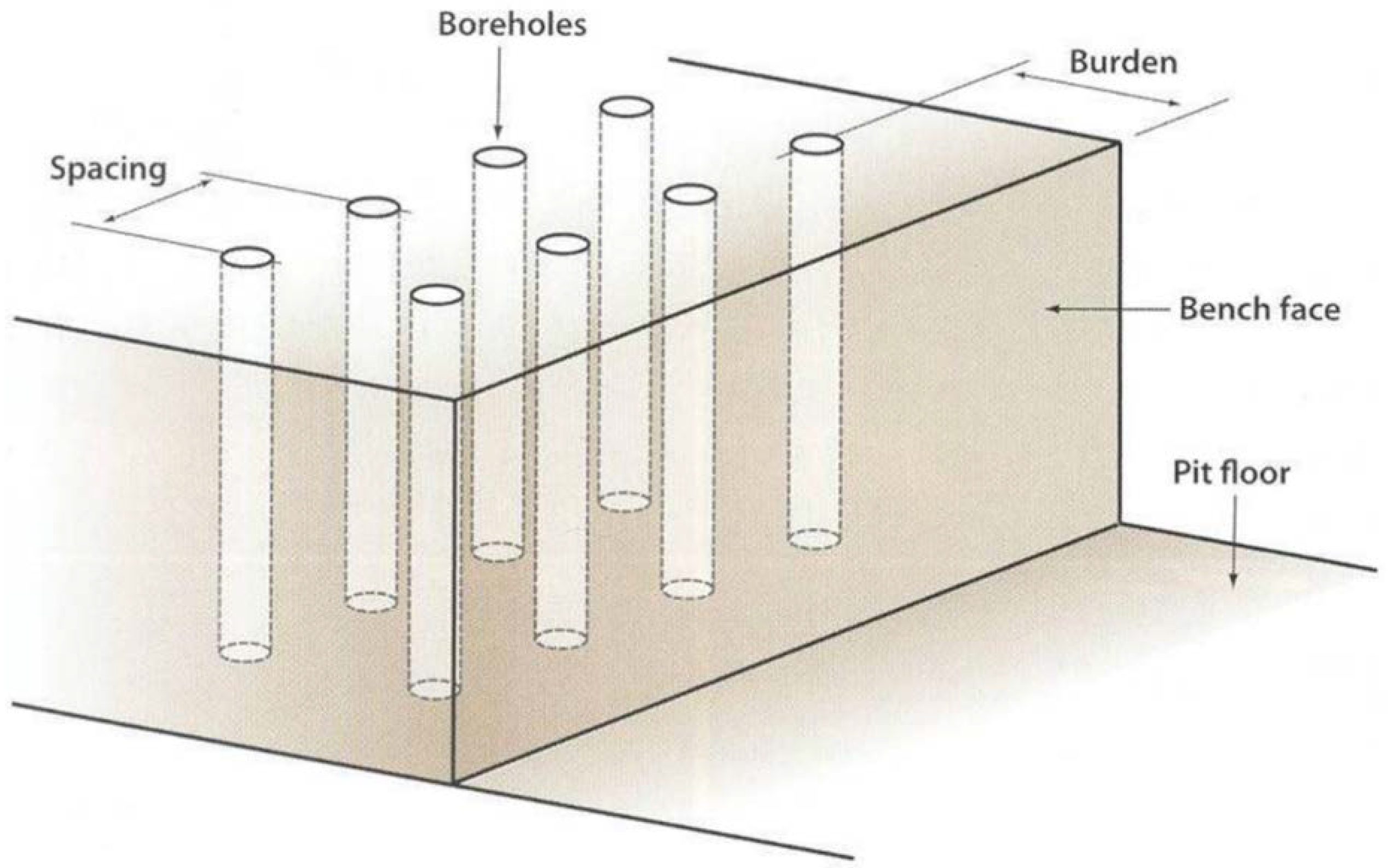
A general scheme, showing the meaning of the terms Ec and Vc (with reference to Table 1 and Table 2) is shown in Figure 4.
The accuracy of the result is mainly influenced by the following factors: geological features; geomechanical characteristics of the medium; presence of water; inclination of the final profile; and expected life span of the intervention (example: 1 year; 5 years; unlimited).
However, it should be remembered that the main factor affecting the success of the result, in each of the techniques described below, is the drilling accuracy [6].
- Mechanical cutting:
- -
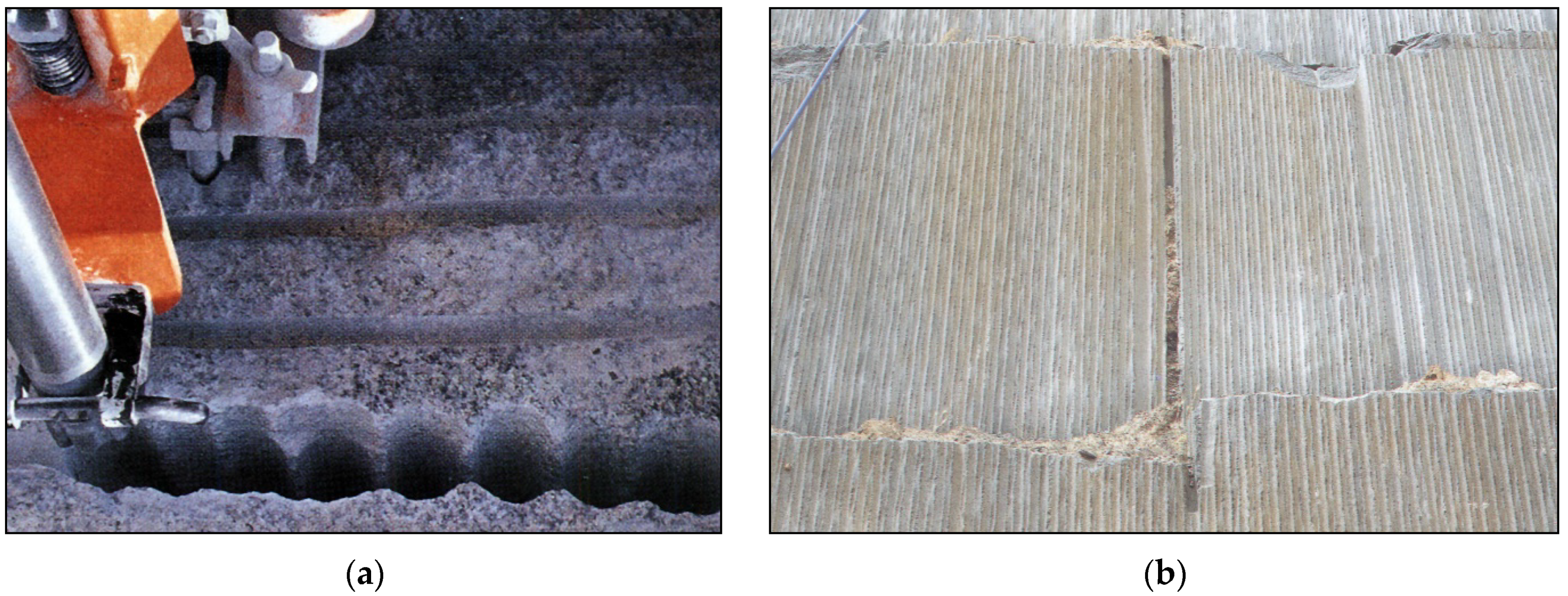
- Line drilling: This technique consists of making a single row of side-by-side and interfering holes, thus obtaining a discontinuity between the material to be removed and that intended to remain in place. Figure 5 shows an example of this technique. The artificial discontinuity allows the dampening of the vibrations generated during the production blast, thus obtaining a final excavation profile with good geomechanical characteristics [7].
- -
- Drilling diameters between 38 and 76 mm are normally adopted. Line drilling is mainly applicable in homogeneous rock masses with weak fractures; its application is also generally limited due to some contraindications, including the difficulty in predicting the certainty of the effect, except in very homogeneous rocks;
- -
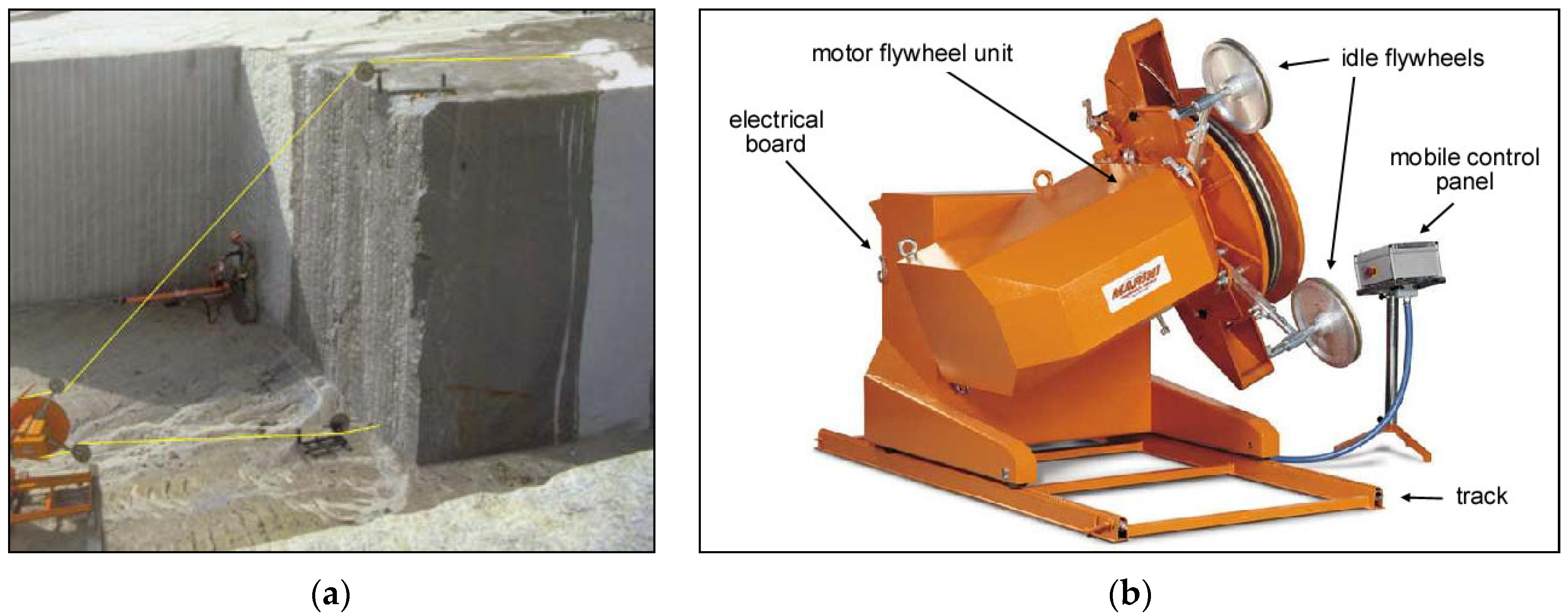
- Diamond wire saw: Cutting with diamond wire is the most widespread technology today in both soft and hard stone quarries, due to the considerable progress in sintered beads, which have made it possible to overcome the problems related to the abrasiveness of the materials to be cut. Its introduction has deeply modified the mode of work in stone quarries, allowing very high productivity and improving aspects of health and—with the due precautions—safety at work. The “standard” application of the wire entails the creation of a closed circuit within which the wire runs at high speed, always cooled by flowing water; the stone is progressively cut by the creation of a deeper and deeper kerf. The circuit for the wire is established via the preliminary drilling of two intersected holes, virtually positioned along the edges of the rock portion to isolate them. The wire is then inserted into this path, closed as a ring, and positioned around the external edge of the motor flywheel of the machine. During the cut, the machine moves backwards, usually running on tracks, thereby keeping the wire in continuous tension and in contact with the rock, thus producing a cut through progressive abrasion of the rock mass. The cutter is able to operate at different angles by simply tilting the motor flywheel. A scheme of a standard application is shown in Figure 6, together with details of the main components of the machine;
- -
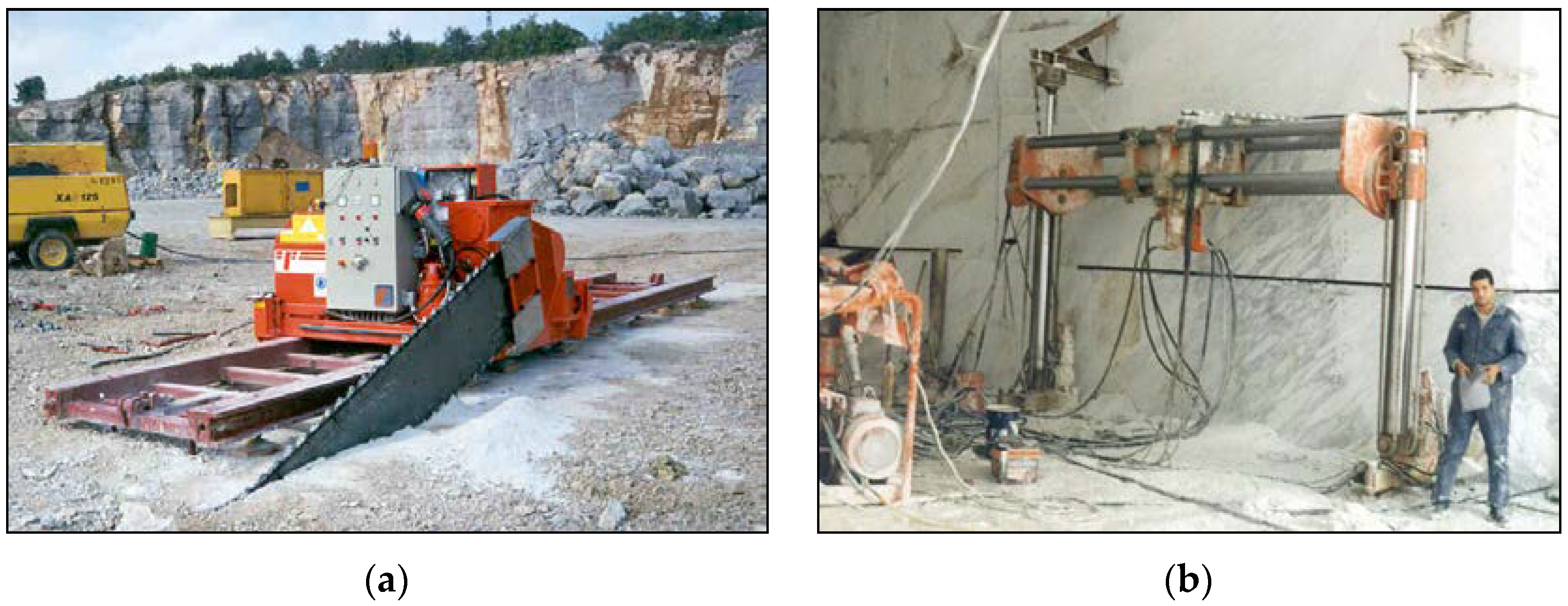
- Chain saw: These are produced in two principal versions, that differ in terms of technical solutions: adopted to operate either on a bench, or in underground quarries (Figure 7). In the “bench type”, the machine is composed of an engine mounted on a frame and connected to a mobile arm, along which runs a toothed chain. The machine can run on rails through a rack. The engine unit, with a power usually ranging from 44 to 60 kW, includes three electro-hydraulic systems, respectively devoted to the movement of the chain, the movement of the arm, and the movement of the frame on rails. The tools are made from sharp pieces of widia, or from polycrystalline diamond (Stratapack), lodged on special supports fixed along the chain. The chain runs along the perimeter of the arm, continually lubricated by grease. The arm, capable of 360° rotation, consists of a tabular-shaped steel element (~40–50 cm wide and 34 mm thick) whose length does not usually exceed 5 m (even though arms up to 10 m in length have been made). The cut has a total thickness of 38–42 mm, a theoretically endless length (horizontally), but a depth limited by the length of the arm. The parameters needed to optimize the relationship between cutting speed and tool wear are the advancement speed of the machine (cm/min) and the rotation speed of the chain (m/s). In the “tunnel type”, the arm is mounted on a tubular frame, separated by the engine unit. The arm is usually 3.5 m long, while the frame is 5–6 m wide and 3.2–4.5 m high. As a result of the movement of the frame, both horizontal and vertical cuts can be performed.
However, how is it possible to judge whether a certain excavation work has been performed correctly in terms of final profile? Of course, the question is challenging, but it is a direct means of introducing the concept of the quality of the work done. Perfection is practically never reached, but it can be used as a goal to judge the quality of the result, which will be better the closer it gets to the perfect result. Quantitative indicators of the “distance from the perfection of the result” must be used, along with criteria to distinguish the imperfection that is to be attributed to the medium from that which belongs to defects in the design or execution, and which can therefore be improved by the operator.
The main points to be examined concern the outline of the project and the state of the walls. In D&B applications, the ideal result would consist of the perfect coincidence of the plane of the contour holes with the residual wall; this rarely occurs. Ordinary blasts usually involve more rock than the design provides and, even when the excavated volume matches the calculated one, it is rarely distributed as the design predicts.
Apart from any errors in the positioning and direction of the holes, the most frequent discrepancies between the actual and the ideal result are:
- Retraction of the edge of the residual bench with respect to the alignment of the mouths of the contour holes;
- Protrusions and indentations of the bench with respect to the alignment of the holes;
- Vertical profiles of the face not being straight, as specified by the drawing, but with indentations and overhangs.
These inaccuracies during excavation make the correct setting of the next blast difficult or impossible; at the end of the work, the damage will consist of the failure to respect the final outline.
Checking the extent of the inaccuracies naturally implies the detection of a certain number of vertical profiles of the residual face, regularly spaced out and in a sufficiently statistically significant number to rebuild an average profile.
The results of the surveys are compared with the project to calculate the excess volume removed (overbreak) compared to what was foreseen by the design geometry.
With an engineering approach, two very useful synthetic indicators of the goodness of the result can be obtained from the survey:
- The average overbreak OB (m), which is the ratio between the volume removed in excess and the face area;
- The average backbreak, RS (m), which is the average setback of the edge of the bench with respect to the alignment of the contour holes (this indicator is easier to detect than the previous one).
The most frequent cause of excessive backbreak is an excessive charge, but it is certainly not the only one, and on the other hand it is not possible to solve the problem by simply reducing the charge, because this can harm fragmentation.
Another very useful and easy-to-detect indicator is the so-called half cast factor (HCF), given by the ratio (percentage) between the total length of “half casts of the holes” observable on the residual wall after the blast and the total length of the contour holes that have been drilled and blasted.
3. Applications
3.1. Presplitting
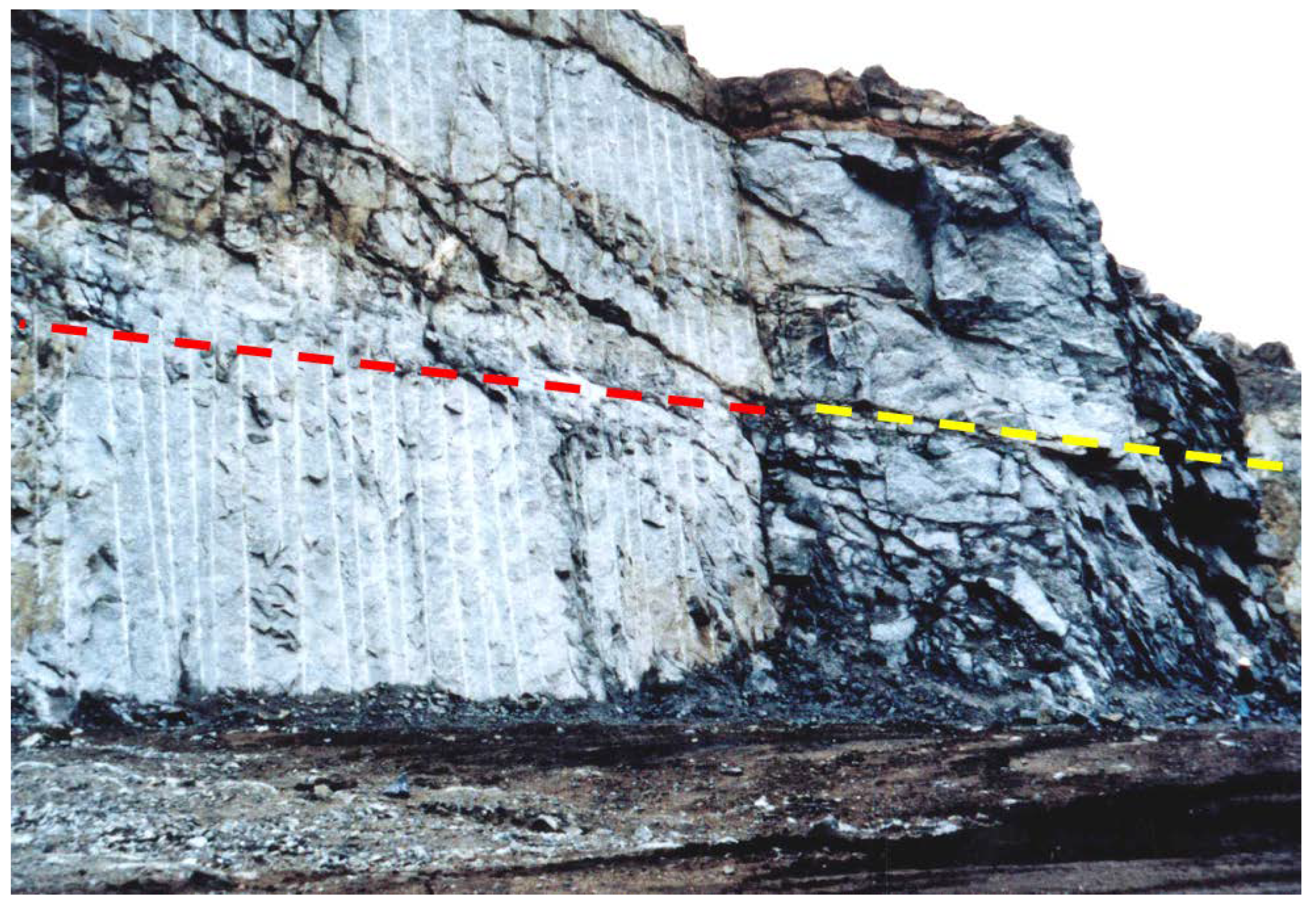
The first important uses of this technique were in the field of rock excavation performed by explosives; it has led, over time, to a currently mature and widespread solution (Figure 8). The split surface is a fracture obtained by applying a well-measured and -directed tensile impulse to the rock. This is the cheapest way, in terms of time and energy costs, to obtain a discontinuity, which has practically no limits in terms of extension. However, the accuracy of the surface and the certainty and predictability of obtaining the desired effect still need to be improved, especially in anisotropic and inhomogeneous materials.
A schematic representation of the presplitting theory is shown in Figure 9, where two charges are triggered simultaneously in adjacent holes; the collision of the shock waves deriving from the detonation stresses the rock bridge between the charge axes, producing a clear fracture [10]. This fracture subsequently widens as a result of the expansion of gases, depending on three factors: (1) the properties and conditions of the rock; (2) the spacing between the holes; and (3) the amount and type of explosives. Following the detonation of the charges, a discontinuity is thus obtained, which must minimize or eliminate the overbreak due to the subsequent production blast, and which gives rise to a regular and flat wall. Two examples of holes charged according to the conditions imposed by the presplitting are shown in Figure 10.
Figure 11 shows a scheme for applying presplitting to a production blast near the final pit slope. In this scheme it was assumed that vertical drilled holes would be used for the production blast, while the presplitting holes were made with an inclination of ~55°—considered suitable to ensure the stability of the residual bench. To make a good connection between the last row of production holes and the presplitting row, while also avoiding the formation of a rock prism of too big volume—which would involve the need to perform a secondary breakage—an additional row of holes with an inclination of ~70° was performed; this row has a length of 3.6 m, in order to avoid convergence between the holes, with consequent excessive concentration of the charge at the bottom.
In the scheme of Figure 11, the presplitting holes are triggered simultaneously (0 ms delay), whereas the production blast holes are microdelayed (row by row, starting from the first row closest to the free surface) according to a sequence of 30 ms; the total duration of the blast is therefore 270 ms.
Presplitting is more accurate than smooth blasting, but has the limit of not being conveniently applicable underground (especially in tunneling), where the presence of only one free surface could compromise the result, giving rise to the propagation of unwanted fractures in the rock mass [12,13,14,15].
By combining the action of explosives with a partial mechanical notch, an improvement in the result can be obtained, although a very significant increase in time is required; this approach has been tried, with some success, for decades (Figure 12). Similar improvements—again at the cost of a reduction in areal productivity—can be achieved by reducing the spacing between the holes [16], up to the purely mechanical notch obtained through line drilling (Figure 4). It is still worth mentioning the case of the so-called “splitting” (Figure 13), which is applied to the detachment of regular blocks: the fracture has the purpose of isolating intact blocks that will be removed and then squared for commercial purposes. The appearance of any other fracture than the desired one must be ruled out. The blast, conceptually similar to the presplitting, consists of an alignment of parallel holes, with small and regular spacing (usually 6–10 times the diameter), weakly loaded with strongly decoupled charges—such as detonating cord—or with an explosive with very low disrupting power and low detonation pressure, lying strictly in the desired detachment plane, which are detonated simultaneously. Blasts of this type require at least three free walls to allow for a small displacement of the block, and are commonly applied to the exploitation of hard, siliceous rocks (granites, gneiss, etc.).
3.2. Smooth Blasting
The most important applications of smooth blasting are in the fields of tunneling and trenches, where the ideal blast results in minimal damage to the rock that remains and a minimal overbreak. For a lined tunnel, less overbreak means less concrete to fill the excess voids [18].
Because controlled blasting generally requires more blast holes, it takes longer to execute compared to a production blast; it requires careful design and selection of all aspects of the round—geometry, hole diameter, hole charges, hole spacing and burden, and delays—as well as careful execution of the work [19]. One of the keys to successful controlled blasting is the precise drilling of blast holes. Deviations of blast holes from their design quickly lead to altered spacing and burden [20], causing blast damage and irregular surfaces. Modern hydraulic drills allow for good precision, but the highest precision is obtained thanks to computer-controlled drill jumbos in homogeneous rock.
An experimental study was carried out during the excavation of a tunnel in an altered gneiss in northern Brazil [4]; the excavation was performed close to the surface (average overburden of about 30–40 m); RMR was estimated through 32 measurements, and a mean value of 47 was found (class III, according to [21]), with only two exceptions in Class IV. Both parallel holes and V-cuts were used for the tunnel excavation; the schemes of the blasts are given in Figure 14 and Figure 15.
For the smooth blasting, a spacing of 0.51 m between the holes (ø 45 mm) was selected, signifying ~10 diameters. The contour holes were weakly loaded, as shown in Figure 16. Figure 17 shows the poor quality of the profile obtained (HCF lower than 30%), although contour blast holes were charged with 40 g/m of detonating cord and buffer blast holes were employed to improve the result. The blasts were carried out very carefully, respecting the drilling design, loading, and timing; buffer holes were employed to increase the chance of success of the smooth blasting, but in almost all cases the HCF was not satisfactory. In this case, the explosive appears not to be the most suitable choice, due to the persistency of rock discontinuities that affect the success of the blasts. It must be noted that employing explosives in RMR class IV can be less productive and more damaging than other techniques [22]. According to [23], the damage can be correlated with the detectable peak particle velocity in the rock. The potential instability caused by the blast should be taken into consideration during rock characterization for the calculation of the supports. The importance of minimizing the fracturing around the tunnel by correctly choosing the excavation technique as a function of RMR is also emphasized by [24]. Research into the quality of blasting, then, should not only involve the technological problems, but also the rock mass characteristics, as the two are strictly connected.
3.3. Mechanical Cutting
These are techniques that do not involve the use of explosives and, therefore, have a higher cost in terms of specific excavation energy. Line drilling, which is only rarely economically reliable in ordinary excavations, is probably the most dated; drilling systems have also been created with the express purpose of performing carvings (in soft rocks, since the first half of the 20th century and, more recently, in hard rocks as well).
An intrinsic weakness of the cutting system of line drilling is that it implies the pulverization of a volume of rock much greater than what is needed; another is posed by the difficulty of precisely guiding a tool carried by a necessarily slender rod.
Cutting methods using drag tools on flexible tool holders (diamond wire and chain saw cutters) are, in principle, even more promising (Figure 18 and Figure 19).
The development of these techniques for hard rocks essentially took place in the sector of extraction and initial squaring of dimension stone, but it is interesting to carefully follow their extension—albeit still sporadic—to other sectors, while remembering that, as with line drilling and presplitting, the chances of success are very low in fractured rocks.
It should also be considered that, apart from a few prototypes of chain cutters expressly designed to pre-cut the contour of tunnels in soft rocks—and with the aim of also allowing the pre-lining of the volume to be removed—there has been, to date, the occasional use of machines especially made for the extraction of ornamental stones, adapted to a different purpose.
4. Comparison of the Techniques Examined
A fair economic comparison of the techniques described above is not yet possible; however, it is useful to consider some parameters that certainly have an influence on cost and applicability (Table 3).
Leaving aside smooth blasting which, despite being widely used, works in conceptually different terms compared to other techniques, the following parameters have been chosen for the analysis:
- a.
- Volume of rock removed per unit of surface (m3/m2);
- b.
- Average hourly productivity of cutting surface per kW engaged (m2/kWh);
- c.
- Usual range of variation of the machine power (kW);
- d.
- Limits of the height (or depth) h and length l of the cut to be made (m).
Some clarifications are needed:
- 1.
- In the case of presplitting, it is assumed that the most commonly adopted diameter Ø is used for long holes made with a heavy drilling machine (50 mm) and a spacing of around 10 diameters; obviously, the use of smaller diameters, larger spacing or, possibly, longitudinal notches on the wall of the holes can lead to a reduction in the volume to be sacrificed, although not necessarily giving rise to an improvement in the result;
- 2.
- Reference is made to the net production, referring only to the working hours of the machine—without considering the time required for installation, repositioning, tool change, hole loading in the case of presplitting, etc.—and to the installed power; this is not, therefore, an energy cost, but a rough indicator of the latter;
- 3.
- The usual value of the installed power of a single machine is reported; naturally, in the case of presplitting, several machines can easily be used in a single operation, while this rarely happens with the other techniques;
- 4.
- The symbol ∞ indicates, for the length, the case in which there is no limit; of course, even in these cases, there is the need to reposition the machine as the cutting proceeds;
- 5.
- The product b∙c is the net productivity of a single average machine (installed power).
The values shown are approximate, but they indicate how difficult it remains to displace presplitting from its position as a technique of minimal cost and maximal productivity. However, the other techniques can be taken into consideration when it is necessary to obtain:
- A more satisfactory solution to the problem of isolation from vibratory effects (which will never be complete, since the elastic waves can diffract around the notch) which, in the case of presplitting, is due to the fact that the notch itself generates a considerable seismic disturbance;
- A remarkable regularity of the wall;
- The exclusion of the propagation of new fractures to the rock, which must remain in place.
Such cases have in common the need to carry out particularly sophisticated works.
5. Examples of Application and Perspectives of Mechanical Cutting Techniques
A simplistic approach would suggest that the field in which these expensive isolation techniques could most easily spread is that of rock excavation works involving large volumes, as the surface/volume ratio (and, therefore, the incidence of the largest operation unit cost) decreases as the volume increases.
On the other hand, it can be seen that the still-sporadic examples reported in the literature concern works involving the removal of small volumes, and this probably happens in cases where both the unit cost and the unit fee are higher. Furthermore, these are generally surgical operations on large artifacts rather than natural bodies.
In ornamental stone quarries, it is quite common to make cuts—mostly with a diamond wire saw—intended solely to isolate a volume, which must subsequently be removed from the deposit that will be “gently” treated to obtain healthy blocks. An economic comparison with civil works regarding the additional cost of mechanical cuts compared to an ordinary presplitting—which would solve the same problem, albeit less perfectly—may not be fair, as the quarry manager already has machinery and workers available. Moreover, in ornamental stone quarries, the work schedule is not pressed by the need to minimize the duration of the operation, the execution of which is the preparation of a future activity that can be superimposed on ordinary production. However, a comparison of the times can be established by taking the values obtained from the result of the operations actually performed and applying them to a hypothetical case.
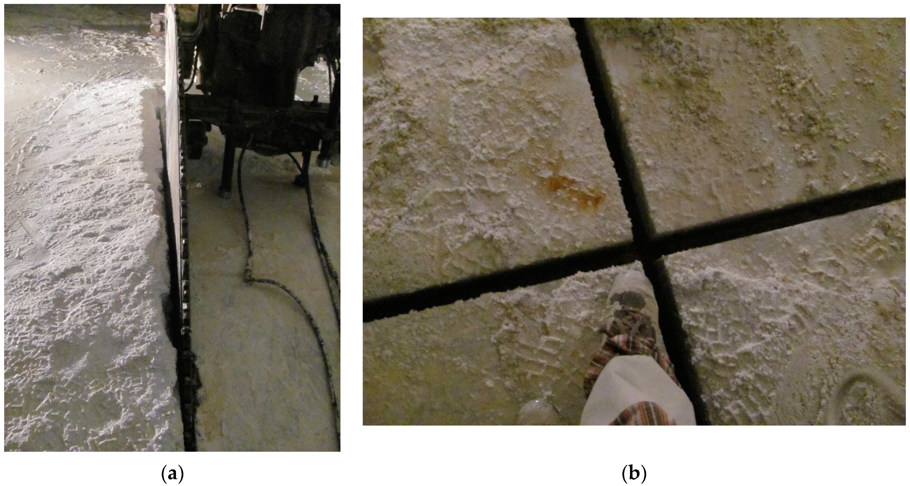
A conceptually similar operation is quite common in the underground exploitation of ornamental stones and, above all, of slates. A room must be created above the bench to be exploited, in the non-exploitable rock of the roof, in which the machines designed to cut and extract the commercial blocks from the underlying layer operate. These chambers are excavated with explosives, but by making a preliminary insulation cut; this cut can be performed by presplitting, but this practice tends to be abandoned, as it does not sufficiently guarantee to exclude the propagation of fractures to the useful bench. The machines currently used are chain cutters, which are also used for rocks harder than ordinary marble (not yet in granite, however) due to the diamond-sintered tools. The gross time required to cut 1 m2 is approximately 8 min, with an average productivity of approximately 7.5 m2/h.
Certainly, presplitting is faster and less expensive than mechanical cutting, but this alternative should be taken into consideration for cases where the perfection of the cut and the regularity of the surface are essential; moreover, although in the field of D&B an optimum has arguably already been achieved, significant progress is still lacking in mechanical cutting:
- The yield of diamond wires—rarely used in granite until the 1990s, as it did not exceed 5 m2/m—has risen to about 13 m2/m;
- The applicability of chain cutters—practically limited to limestone rocks—has been extended to serpentines and sandstones as a result of new materials for tools, while the machines also reach net productivity in these rocks similar to that in marble;
- Longer tool life, in any case, is reflected in higher gross productivity.
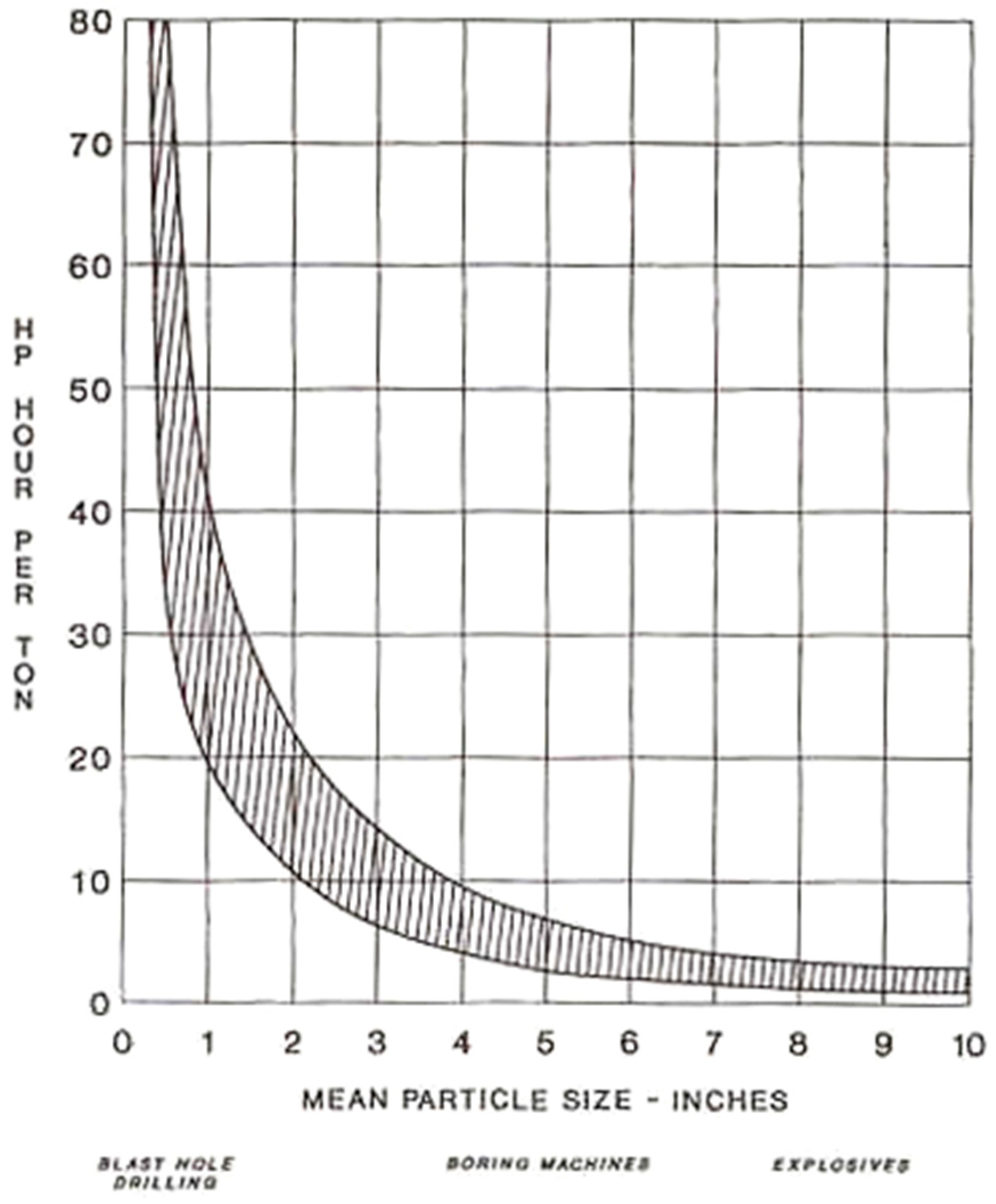
However, it is important to take into account the specific excavation energy derived from drilling (presplitting or line drilling) and from cutting operations. Since this parameter is related to the grain size distribution of the materials after the excavation, a finer fragmentation means a higher energy cost. Drilling, by comparison with mechanical excavation, requires the greatest amount of specific energy (Figure 20), but the cut being made with microtools such as diamond wire or chain saws forces the tools to break up portions of rock with a very small depth of cut (generally, a few tenths of a mm) and, therefore, involves a very high energy cost.
6. Conclusions
In rock excavation, obtaining a final result with contours perfectly in compliance with the project is always a good accomplishment. Commonly, it is good practice to perform the excavation work with the intent of optimizing the specific energy, and this concept should also be applied in the specific case of contour blasting. In this paper, an overview of the most important techniques is reported, with the purpose of providing a smart, easily readable tool as a support for design work.
As for the techniques based on explosives, descriptions of presplitting and smooth blasting are provided by operative schemes and by justifying the order of magnitude of the blasting parameters—fundamental details for better and quickly understanding the philosophies of these methods. Pertaining to mechanical cutting, line drilling, wire diamond saws, and chain saws are described, providing useful information to readers for choosing the best technology for the required quarry application.
Taking into account the specific excavation energy, contour methods based on D&B are far more convenient compared to mechanical cutting techniques but, of course, cannot be applied to every situation. On the other hand, diamond wire saws and chain saws are undoubtedly the most suitable techniques for quarries, since they combine both the extraction and the contour phase, where the shape and integrity of the stone are crucial for the market.
As a final remark, in Table 4, the pros and cons of each technology are provided. This information should not be interpreted in absolute terms, and the comparison is therefore general and indicative. In fact, it is necessary to take into account that the cases examined are very different, and are applicable to very different situations. There is no doubt that the exploitation of ornamental stones (where, at most—for lack of other less expensive techniques, or for the impossibility of their use—line drilling can be adopted to perform a vertical or horizontal cut), for instance, is not comparable with the excavation of tunnels or trenches by D&B (where line drilling is practically never used); the intent is therefore to show the different possibilities and limits of “precision” rock excavation, while remaining aware that the comparison can only be qualitative, and is often impracticable, given the very different circumstances.
In conclusion, the development and success of mixed excavation techniques is expected: the explosive does the brutal work for which it was intended at low cost, while a mechanical cutting system sets the boundaries to its action.
Author Contributions
Conceptualization, M.C. and C.T.; methodology, S.S. and C.T.; formal analysis, M.C. and C.D.; investigation, S.S.; data curation, M.C. and C.T.; writing—original draft preparation, M.C.; writing—review and editing, M.C. and C.T.; visualization, S.S.; supervision, M.C. All authors have read and agreed to the published version of the manuscript.
Funding
This research received no external funding.
Data Availability Statement
Not applicable.
Conflicts of Interest
The authors declare no conflict of interest.
References
- Hermanson, J. Rock Drilling on a vertical Wall: Problem solving at Crazy Horse. J. Explos. Eng. 1996, 13, 12–14. [Google Scholar]
- Muehl, P. Nose blasts present explosives engineering challenges. J. Explos. Eng. 1993, 11, 43–45. [Google Scholar]
- Seccatore, J.; Romero Huerta, J.; Sadao, G.; Cardu, M.; Galvão, F.; Finoti, L.; Rezende, A.; Bettencourt, J.; De Tomi, G. The influence of charge distribution on the grindability of the blasted material. In Proceedings of the 11th International Symposium on Rock Fragmentation by Blasting, FRAGBLAST11, Sydney, Australia, 24–26 August; The Australasian Institute of Mining and Metallurgy: Carlton, Australia, 2015; p. 6. ISBN 9781925100327. [Google Scholar]
- Seccatore, J.; Golin, F.; Cardu, M.; Munaretti, E.; Bettencourt, J.; Koppe, J.C. Evaluating the Effects of Non-coaxial Charges for Contour Blasting. In Proceedings of the 11th International Symposium on Rock Fragmentation by Blasting, FRAGBLAST11, Sydney, Australia, 24–26 August; The Australasian Institute of Mining and Metallurgy: Carlton, Australia, 2015; p. 12. ISBN 9781925100327. [Google Scholar]
- LaMotte, A. Blasters’ Handbook, 175th ed.; E.I. du Pont de Nemours & Co.: Wilmington, DE, USA, 1977; p. 494. [Google Scholar]
- Heiniö, M. Rock Excavation Handbook for Civil Engineering; Sandvik—Tamrock Corp.: Skjetten, Norway, 1999; p. 364. [Google Scholar]
- Haoran, H.; Wenbo, L.; Peng, Y.; Ming, C.; Qidong, G. A vibration-isolating blast technique with shock-reflection device for dam foundation excavation in complicated geological conditions. Shock Vib. 2018, 2018, 8029513. [Google Scholar]
- Primavori, P. Pianeta Pietra; Giorgio Zusi Editore: Verona, Italy, 1999; p. 326. [Google Scholar]
- Hoek, E.; Brown, B.T. Practical Estimates of Rock Mass Strength. Int. J. Rock Mech. Min. Sci. 1997, 34, 1165–1186. [Google Scholar] [CrossRef]
- Chu, H.; Yang, X.; Li, S.; Liang, W. Experimental investigation of the propagation and attenuation rule of blasting vibration wave parameters based on the damage accumulation effect. Shock Vib. 2018, 2018, 2493149. [Google Scholar] [CrossRef]
- International Society of Explosives Engineers. ISEE Blasters’ Handbook, 18th ed.; International Society of Explosives Engineers: Cleveland, OH, USA, 2011; p. 1030. [Google Scholar]
- Cunningham, C.V.B.; Goetzsche, A.F. The Specification of Blast Damage Limitations in Tunnelling Contracts. Tunn. Undergr. Space Technol. 1990, 5, 193–198. [Google Scholar] [CrossRef]
- Zhou, Z.; Cheng, R.; Cai, X.; Jia, J.; Wang, W. Comparison of Presplit and Smooth Blasting Methods for Excavation of Rock Wells. Shock Vib. 2019, 2019, 3743028. [Google Scholar] [CrossRef]
- Singh, P.K.; Roy, M.P.; Paswan, R.K. Controlled blasting for long term stability of pit-walls. Int. J. Rock Mech. Min. Sci. 2014, 70, 388–399. [Google Scholar] [CrossRef]
- Wang, F.; Tu, S.; Yuan, Y.; Feng, Y.; Chen, F.; Tu, H. Deephole pre-split blasting mechanism and its application for controlled roof caving in shallow depth seams. Int. J. Rock Mech. Min. Sci. 2013, 64, 112–121. [Google Scholar] [CrossRef]
- Hagimori, K.; Terada, M.; Ouchterlony, F.; Furukawa, K.; Nakagawa, K. Using slot drilling to reduce vibrations and damage from tunnel blasting in urban areas. In Proceedings of the 4th International Symposium on Rock Fragmentation by Blasting, Vienna, Austria, 5–8 July 1993; pp. 97–104. [Google Scholar]
- Niklasson, B.; Keisu, M. New techniques for tunnelling and drifting. In Proceedings of the 4th International Symposium on Rock Fragmentation by Blasting, Vienna, Austria, 5–8 July 1993; pp. 167–174. [Google Scholar]
- Satici, Ö. Drilling and Blasting as a Tunnel Excavation Method; Middle East Technical University, Department of Geological Engineering: Ankara, Turkey, 2006; p. 24. [Google Scholar] [CrossRef]
- Qiu, X.; Shi, X.; Gou, Y.; Zhou, J.; Chen, H.; Huo, X. Short-delay blasting with single free surface: Results of experimental tests. Tunn. Undergr. Space Technol. 2018, 74, 119–130. [Google Scholar] [CrossRef]
- Langefors, U.; Kihlström, B. The Modern Technique of Rock Blasting, 2nd ed.; Almqvist & Wiksell: Stockolm, Sweden, 1967; p. 405. [Google Scholar]
- Bieniawski, Z.T. Engineering classification of jointed rock masses. Trans. S. Afr. Civ. Eng. 1973, 15, 335–344. [Google Scholar]
- Innaurato, N.; Mancini, R.; Cardu, M. On the Influence of the Rock Mass Quality on the Quality of the Blasting Work in Tunnel Driving. Tunn. Undergr. Space Technol. 1998, 13, 81–89. [Google Scholar] [CrossRef]
- Page, C.H. Controlled blasting for underground mining. In Proceedings of the 13th Conference on Explosives and Blasting Techniques; International Society of Explosives Engineers (ISEE), Miami, FL, USA, 30 January 30–2 February 1987; pp. 33–48. [Google Scholar]
- Holmberg, R.; Larsson, B.; Sjoberg, C. Improved stability through optimized rock blasting. In Proceedings of the 10th Conference on Explosives and Blasting Techniques; International Society of Explosives Engineers (ISEE), Orlando, FL, USA, 29 January–1 February 1984; pp. 166–171. [Google Scholar]
- Mancini, R.; Cardu, M. Scavi in Roccia—Gli Esplosivi; Hevelius Edizioni Srl: Benevento, Italy, 2001; p. 295. [Google Scholar]
Figure 1.
(a) the Crazy Horse Memorial, a Native American monument, carved with explosives in the granite of the Black Hills, South Dakota [1]. (b) dimensions of the face of the “Crazy Horse” sculpture, and detail of the execution phases of the profile’s roughing by explosives. Whole face: height 26.7 m, width 17.7 m; forehead: height 9.7 m; eyebrows: height 6 m, width 2.3 m; eye opening: height 2.4 m, width 1 m; nose: height 8.2 m, width 5.2 m; lips: max height 1.8 m, max width 5.8 m [2].

Figure 2.
(a) Examples of ordinary blasts: above, production blast in a limestone quarry, Brazil [3]; (b) tunnel face after a blast: the poor quality of the contour obtained is noticeable [4].

Figure 3.
Examples of smooth blasting: (a) half cast clearly observable after a blast in tunnel driving; (b) result of a contour blast in open-pit mining [4].
Figure 3.
Examples of smooth blasting: (a) half cast clearly observable after a blast in tunnel driving; (b) result of a contour blast in open-pit mining [4].

Figure 4.
Example of a blasting pattern with indication of the main parameters involved. In particular, the representation of the terms Ec and Vc (referring to Table 1 and Table 2) should be noted [5].

Figure 5.
(a) Drilling of contact holes in granite using the line-drilling technique; (b) a granite quarry face cut with line drilling [8].
Figure 5.
(a) Drilling of contact holes in granite using the line-drilling technique; (b) a granite quarry face cut with line drilling [8].

Figure 6.
(a) Cutting by diamond wire through a traditional “descending loop” configuration; (b) the diamond wire sawing machine, where the main components are shown.
Figure 6.
(a) Cutting by diamond wire through a traditional “descending loop” configuration; (b) the diamond wire sawing machine, where the main components are shown.

Figure 7.
(a) A chain cutter operating on a bench to perform a vertical cut; (b) the version commonly adopted for underground use: the versatility of this machine allows the creation of additional free surfaces in bottom-blinded openings of “weak” stone quarries, for which it is very frequently adopted.

Figure 8.
Comparison between the results achieved with presplitting blasting (left—red dashed line) and normal blasting (right—yellow dashed line) for a surface excavation [9]. If the parallelism of the holes, the correct spacing, and a good decoupling between the diameter of the holes and that of the charge are respected, the result is a profiled wall, where no new fractures are observed in addition to the pre-existing ones.

Figure 9.
Schematic representation of the presplitting theory [11].
Figure 9.
Schematic representation of the presplitting theory [11].

Figure 10.
(a) Typical presplit column load: the decoupling of the charge with respect to the hole diameter is very clearly observed; (b) general air-decked borehole: the bottom charge is triggered by a primer, but most of the hole is unloaded and, in contact with the stemming, at the hole mouth, a plug is inserted with the purpose of “trapping” the air cushion and ensuring a lower impact of the detonation. In both cases, the primer is at the bottom of the hole [11].

Figure 11.
Example (vertical section and plan view) of the application of the presplitting to a production blast close to the final pit slope.
Figure 11.
Example (vertical section and plan view) of the application of the presplitting to a production blast close to the final pit slope.

Figure 12.
(a) Reduced spacing as a result of holes (notched by water jet) able to guide the fracture in the wanted direction; (b) gas pressure necessary for the propagation of the fracture in a blast hole with a diameter of 89 mm, performed in granite, depending on the length of the notch. pc = critical pressure without notch; pcn = critical pressure with notch [17].

Figure 13.
(a) Application of splitting to a granite bench (the progressive subdivision into slices and the overturning on the yard to proceed with the squaring operations is noticeable); (b) result, consisting of two vertical, perpendicular surfaces (the cut is very regular); (c) detail of the holes charged with detonating cord (which assures a decoupling of ~10 between the holes and the charge—very high compared to presplitting).

Figure 14.
(a,b): Scheme of parallel holes cut. Pull: 2.5 m; surface: 30 m2; total charge: 119 kg; detonating cord 40 g/m: 90 m; powder factor: 1.32 kg/m3; holes’ diameter: 45 mm; delay time: 25 ms. (a) The numbers refer to the delay sequence; (b) quotes are expressed in meters [4].
Figure 14.
(a,b): Scheme of parallel holes cut. Pull: 2.5 m; surface: 30 m2; total charge: 119 kg; detonating cord 40 g/m: 90 m; powder factor: 1.32 kg/m3; holes’ diameter: 45 mm; delay time: 25 ms. (a) The numbers refer to the delay sequence; (b) quotes are expressed in meters [4].

Figure 15.
(a,b) Scheme of a V-cut. pull: 3.0 m; surface: 30 m2; total charge: 119 kg; detonating cord 40 g/m: 90 m; powder factor: 1.32 kg/m3; holes’ diameter: 45 mm; delay time: 25 ms. (b) The numbers refer to the delay sequence [4].
Figure 15.
(a,b) Scheme of a V-cut. pull: 3.0 m; surface: 30 m2; total charge: 119 kg; detonating cord 40 g/m: 90 m; powder factor: 1.32 kg/m3; holes’ diameter: 45 mm; delay time: 25 ms. (b) The numbers refer to the delay sequence [4].

Figure 16.
Details of the charges employed in contour holes [4].
Figure 16.
Details of the charges employed in contour holes [4].

Figure 17.
The poor quality of the obtained contour is noticeable [4].
Figure 17.
The poor quality of the obtained contour is noticeable [4].

Figure 18.
(a) Quarry face cut with diamond wire in a Sardinian granite quarry; (b) detail of the cut with a diamond wire saw in Carrara marble.
Figure 18.
(a) Quarry face cut with diamond wire in a Sardinian granite quarry; (b) detail of the cut with a diamond wire saw in Carrara marble.

Figure 19.
(a) A chain saw performing a vertical cut in Carrara marble; (b) very precise result of the isolation of blocks made by vertical cuts, perpendicular to one another, using the same technique. The thickness of the cut is ~40 mm.
Figure 19.
(a) A chain saw performing a vertical cut in Carrara marble; (b) very precise result of the isolation of blocks made by vertical cuts, perpendicular to one another, using the same technique. The thickness of the cut is ~40 mm.

Figure 20.
Correlation between the energetic cost of excavation of the rock, expressed in CV h/t, and the average size of the fragments obtained, expressed in inches. The “ranges” designate: “Blast Hole Drilling”: drilling of blast holes; “Boring Machines”: machines for the mechanical excavation of tunnels or shafts; “Explosives”: blasting. The highest energy cost is linked to the drilling operation, which forces a small volume of rock (equal to the product of the drilling diameter by the length of the hole) to be reduced to a very fine grain size. On the other hand, the explosive is the operation that requires the lowest energy cost compared to all the other techniques of “mechanical excavation”, since the result of the blast generally gives rise to blocks with a rather coarse size [25].


Table 1.
Range of parameters commonly adopted for presplitting.
| Hole’s Diameter øf | Charge Density qc | Spacing Ec | |||
|---|---|---|---|---|---|
| (mm) | (kg/m) | (m) | |||
| Min øf | Max øf | Min qc | Max qc | Min Ec | Max Ec |
| 38 | 44 | 0.07 | 0.17 | 0.30 | 0.45 |
| 51 | 64 | 0.17 | 0.29 | 0.45 | 0.60 |
| 76 | 89 | 0.17 | 0.66 | 0.45 | 0.90 |
| 102 | 102 | 0.29 | 1.17 | 0.60 | 1.20 |
Table 2.
Common parameters adopted to size the smooth blasting.
| Hole Diameter | Charge Diameter | Charge Density | Spacing | Burden | |
|---|---|---|---|---|---|
| (mm) | (mm) | (kg/m) | (m) | (m) | |
| øf | øc | qc | Ec | Vc | |
| Values measured on site | 32 | 17 | 0.22 | 0.40–0.60 | 0.55–0.75 |
| 51 | 25 | 0.50 | 0.65–0.90 | 0.80–1.20 | |
| Values suggested by [5] | 32 | - | 0.18–0.38 | 0.60 | 0.90 |
| 51 | - | 0.18–0.38 | 0.75 | 1.05 |
Table 3.
Comparison of the possible cutting techniques, according to some selected parameters.
| Parameter | Technique | |||||||
|---|---|---|---|---|---|---|---|---|
| Presplitting | Line Drilling | Chain Saw | Diamond Wire Saw | |||||
| Limestone | Granite | Limestone | Granite | Limestone | Granite | Limestone | Granite | |
| a, m3/m2 | 0.005 | 0.005 | 0.05 | 0.05 | 0.05 | 0.05 | 0.005 | 0.005 |
| b, m2/kWh | 0.3 | 0.15 | 0.03 | 0.015 | 0.2 | 0.1 | 0.2 | 0.05 |
| c, kW | 100 | 100 | 100 | 100 | 50 | 50 | 50 | 50 |
| d, m | 8 ∞ | 8 ∞ | 8 ∞ | 8 ∞ | 5 ∞ | 5 ∞ | 10–20 | 10–20 |
| b∙c, m2/h | 30 | 15 | 3 | 1.5 | 10 | 5 | 10 | 2.5 |
Table 4.
Pros and cons of the contour excavation techniques described.
| Technique | Pros | Cons |
|---|---|---|
| Presplitting | Very accurate | High specific drilling |
| Smooth blasting | Simple to perform | Less accuracy |
| Line drilling | Extremely accurate and versatile | Very high specific drilling |
| Chain saw | Extremely versatile | Applicable only in carbonate rocks |
| Diamond wire saw | Small thickness cut | In traditional applications requires at least two free surfaces |
Publisher’s Note: MDPI stays neutral with regard to jurisdictional claims in published maps and institutional affiliations. |
© 2021 by the authors. Licensee MDPI, Basel, Switzerland. This article is an open access article distributed under the terms and conditions of the Creative Commons Attribution (CC BY) license (https://creativecommons.org/licenses/by/4.0/).
Share and Cite
MDPI and ACS Style
Cardu, M.; Saltarin, S.; Todaro, C.; Deangeli, C. Precision Rock Excavation: Beyond Controlled Blasting and Line Drilling. Mining 2021, 1, 192-210. https://0-doi-org.brum.beds.ac.uk/10.3390/mining1020013
AMA Style
Cardu M, Saltarin S, Todaro C, Deangeli C. Precision Rock Excavation: Beyond Controlled Blasting and Line Drilling. Mining. 2021; 1(2):192-210. https://0-doi-org.brum.beds.ac.uk/10.3390/mining1020013
Chicago/Turabian StyleCardu, Marilena, Simone Saltarin, Carmine Todaro, and Chiara Deangeli. 2021. "Precision Rock Excavation: Beyond Controlled Blasting and Line Drilling" Mining 1, no. 2: 192-210. https://0-doi-org.brum.beds.ac.uk/10.3390/mining1020013