1. Introduction
The advances in mobile computing and hardware designs have enabled the deployment of more efficient functionalities on mobile devices while these devices have become smaller and compact. In underground mining environments, the low rate of mobile device usage is mainly caused by strict safety regulations. Currently, several wired [
1,
2] and wireless communication technologies are available that satisfy the minimum required criteria for the data broadcast speed and range to support remote mining operations and advanced monitoring systems.
The main advantage of wireless communications is mobility within a closed space. In underground mines, wireless technologies can be used to support the mobility of humans and machines in dangerous working areas. In those areas, conventional cable communication can be easily damaged by heavy machinery and may not advance quickly enough with the required expansion of working areas.
As a result, wireless sensor networks (WSNs) have become useful for measuring and monitoring important data, such as in situ stress and strain, air quality, and data from machines in underground mines. Long term in situ stress and strain monitoring systems are necessary to observe the rock conditions in mining excavations. While numerical modelling methods can provide a faster approach, actual measurements from sensors installed around the areas of interest can provide more accurate stress and strain measurements of the surrounding rock.
These measurements can be more valuable if an efficient communication system is present at the working areas and can deliver the data over long distances to important decision making locations, such as the central processing office, which is usually located at the surface. Before communication technologies can be deployed in situ in underground mining environments, extensive measurement campaigns in safe test-bed environments are necessary to estimate the performance of such technology under harsh conditions.
The measured data have shown to be useful in applications such as optimized network design, file download efficiency, user and machine localization, and positioning. In order to successfully develop these algorithms, the path loss properties of the wireless signals, such as the received signal strength indicator (RSSI), are collected from test environments and used to train the algorithms offline. The trained models can then be used for actual navigation and the determination of the users’ positions in realistic scenarios using existing algorithms, such as the k-nearest neighbour (KNN) or triangulation.
Such methods can also be adopted in underground mining environments and will require extensive RSSI measurements in order to understand the effects of different geometries on direct WiFi signals. In scenarios where the data are required to be transferred over long distances, such as to a surface office for further processing, the effect of deep fading is mitigated by simply re-transmitting the signal over a distance where the signal can be received, decoded, and re-transmitted reliably. Hence, adequate knowledge of the propagation properties, such as the received signal strength (RSS) can inform the placement and deployment of transmitter-receiver pairs in the mine in order to achieve reliable data hops to the destination.
In this paper, the practical integration of a multi-sensor, cell monitoring system with a low-complexity WiFi communication system is evaluated in a narrow tunnel, narrow-reef stope, and vertical shaft of an underground mining environment. The data from the sensor is transmitted directly to a mobile phone receiver that is in the transmitter’s line-of-sight (LOS) and non line-of-sight (NLOS). The RSSI as well as throughput performances are evaluated with respect to the distance and geometry of the environments. Using the RSSI data, the path loss propagation properties of the different measurement areas of the mine are also derived. By conducting physical experiments to measure the performance of WSNs, we evaluate the performance in underground mining environments. The results have the potential to inform the transfer speed and signal quality that can be achieved in real severe environments.
This paper is organized as follows: in the introduction, the concept of a wireless monitoring system and path loss model is discussed,
Section 3 introduces the proposed in situ stress monitoring system. In
Section 4 and
Section 5, the principle of the experiment, the RSSI Model for WiFi Direct, and the setup of the experiment are described.
Section 6 and
Section 7 conclude the paper, discussing the results and proposing further steps for expanding the experiment.
2. Related Work
2.1. Wireless Sensor Networks
The efficient monitoring of natural events that pose a safety risk to humans in underground mining environments can assist with improving the health and safety conditions in the environment. Such risks can emanate from rock movement due to stress, imbalances in temperature and ventilation, and smoke and air quality issues [
3]. Generally, in situ stresses increase with depth as, in shallow coal mines, the rate of increase in horizontal stresses as the depth increases is greater than the rate of increase of vertical stress.
On the other hand, with increasing depth, the rate of increase in horizontal stresses decreases. Therefore, a considerable scatter in the in situ stress test data may be due to distinct differences in both the strength and deformation moduli of strata located in different geological environments and coal districts [
4].
In monitoring rock masses in deep underground environments, an extra-deep, multiple-point borehole extensometer was investigated in an iron-ore mine in eastern Jinshandian. The extensometer was demonstrated to be applicable for up to 300 m depth. The in situ monitoring results collected over eight years were analyzed [
5].
WSNs in underground environments can assist with measuring events that include, but are not limited to, temperature, dust, smoke, air pressure, air quality, humidity, rock stress, and movements. In [
6], a review of WSN applications was performed in which the impact of wireless technology, such as ZigBee, was discussed and evaluated for mine collapse monitoring, the tracking of miners in underground environments, and the support of robots for the collection and delivery of data from areas that are inaccessible to humans.
A direct application to gas monitoring was performed in [
7] and fire detection was conducted in [
8], where the authors evaluated the fire detection speed in a Bord-and-Pillar coal mine using WSN. Using simulations, the authors proposed a prevention system capable of detecting the location of fire breakouts in seconds as well as the direction of the fire as it spreads.
While the data from sensors in an underground environment can be collected and analyzed locally, the work in [
9] further discussed the potential of integrating an Internet of Things (IoT) system with the data collected from sensors in underground environments.
Trust models of WSNs security have flourished due to the day-to-day attack challenges, which are most popular for the IoT [
10]. Designing a robust IoT network imposes some challenges, such as data trustworthiness (DT) and power management. In [
11], a repeated game model was used to enhance clustered WSN-based IoT security and DT against a selective forwarding (SF) attack. However, WSN trust models are not considered in this paper, and more details can be found in [
10,
12].
Using the IP protocol, the data collected from the sensing layer can be available in real-time and remotely through cloud storage. Security challenges, however, exist in the sensing layer, suggesting the need for robust security protocols to safeguard the end-to-end delivery of the data. The transmission of the collected data to the remote cloud can suffer from high latency when using current communication technology. By bringing the server relatively closer to the miner, mobile edge computing (MEC) is a promising distributed computation architecture to seize the opportunity of enabling low-cost, and low-latency data collection. These issues are covered in detail in [
13,
14].
In the event of a mine disaster, traditional communication networks can potentially be damaged and disrupted, affecting the ability of mine to understand the underground environment’s conditions. This influences the quality and speed of decisions due to the disruption of real-time information required for mitigating the effect of any problems that may occur underground. Therefore, ZigBee and geographic information systems (GIS) technologies have been suggested to provide more effective communication systems [
15,
16].
Moridi et al. investigated various sensor node arrangements of ZigBee networks for underground space monitoring and communication systems [
17]. The proposed system integration considering WSNs enables GIS to better monitor and control underground mining applications from the surface office.
Based on the capabilities of WSNs in the study, the ZigBee network was considered applicable for near real-time monitoring, ventilation system control, and emergency communication in an underground mine. The outcomes of such application provide promising, suitable network performance in such environments. Moreover, experimental measurements of ZigBee radio waves attenuation were validated by simulation results [
18] for underground mines.
The outcome of this work shows that WSN can be reliable in deploying low data rate applications in underground mine environments, such as ventilation fan remote control, text messaging, and temperature and humidity readings and settings. The system functions of the model were tested and verified in an underground mine in Western Australia [
19].
An overview of wired and wireless communication technologies, such as ZigBee, radio frequency (RF), and very low and very high frequency communication in underground mining and tunnel environments, was reviewed in [
20]. In particular, the different modelling techniques of RF in underground mines show the different path loss propagation properties of the wireless signals, such as roughness, refraction, and sidewall tilt loss.
From the derived models, it is evident that signal propagation in underground mines is heavily influenced by the topology of the environment, such as the corners in tunnels, the unevenness, and tilting of the walls. Such channel knowledge was shown to be important in the deployment and implementation of underground mine applications for tracking and transceiver designs. An integration of a WSN with optic fibres in [
21] was used to deliver the data collected from sensors installed in an underground coal mine to a monitoring centre at the mine surface.
Here, Zhang et al. attempted to address the need for safety by proposing a generic, integrated ambient-assisted living system architecture. A mesh network architecture was demonstrated in the WSN such that a cluster head, in the form of a routing node administers connected sensors, played the role of cluster members in the network [
21].
Such architecture ensures that a broken sensor or broken link to the cluster head does not break down the entire system, while the cluster head manages dual communication with the surface control center. WSN was also integrated with WiFi in [
22]. Here, Tao and Xiaoyang’s system showed that WSN-WiFi applications can be used to extend the reach of the WSN system in low to high data rate applications, such as gas monitoring and video surveillance.
2.2. Applications of the Path Loss Model
The path loss model [
23] for wireless signals can assist with evaluating the RSS of WiFi signals over distance. Other properties describing the fading nature of the signal in the environment, such as shadowing or path loss coefficients, can be determined by direct measurements. These properties not only provide understanding of the effect of the environment on wireless signals but also assist with offline analysis and simulations.
Mobile devices are equipped with RSS functionality. Hence, applications, such as user indoor positioning and navigation [
24,
25,
26,
27,
28,
29,
30,
31] and battery resource management [
32], have emerged. In [
24], the localization accuracy based on RSS was improved by using a priori information obtained from measurements. Introducing the local environment parameters to wireless signal networks enabled better calibration of the WSN.
Aside from the RSSI-based method for fingerprinting and position location, the fine timing measurement (FTM), introduced in IEEE 802.11-2016, uses the properties of the received signal between mobile phone sensors, such as the arrival time and delay, for positioning. Hence, in [
25], a comparison of the FTM technology with RSSI-based indoor positioning over a 2.4 GHz wireless system under realistic scenarios was performed.
The IEEE 802.11-2016 introduced FTM, which uses received signal properties, such as the arrival time and delay, for positioning with mobile phone sensors. Using the least squares (LS) method in a given radius, the position of the user in an indoor environment, transmitting over a 2.4 GHz channel is estimated, with the results showing that FTM improves the positioning when compared with the RSSI method. The statistical processing of RSSI measurements can also be used to process RSSI fingerprint data in order to improve the accuracy and reduce the complexity by reducing the amount of data required during offline processing.
In [
27], a comparison of the accuracy of machine learning algorithms, such as KNN, singular value decomposition (SVM), and decision tree models, was used to classify fingerprinting data used for indoor positioning. The classification enabled offline localization using predictive measures during offline processing.
In [
28], a hybrid of a KNN algorithm and particle filtering algorithm [
29] was adopted to improve the positioning accuracy of a robot in an indoor environment. The effect of Bluetooth interference with the wireless signals on the positioning accuracy was also investigated in [
30]. This was performed by comparing the statistical approaches, such as the Weibull distribution and the probability of occurrence of an observed RSSI measurement.
Studies investigating the propagation of wireless signals in the underground tunnel coal mines go as far back as the work in [
33] done in 1975. In this work, the effect of the geometry of the walls and corners were evaluated over high frequency radio waves in the MHz range. Since then, several works have studied the propagation models of wireless signals over higher frequencies.
The propagation properties of 900 MHz radio signals were measured in [
34] for longwall underground coal mines. In [
35], the delay, impulse response, and power profiles of signals received over 2.4 and 5.8 GHz frequencies were reported for an underground mining environment.
The measurements for LOS and NLOS scenarios show the fading characteristics as Rice and Rayleigh distributions, respectively. In underground environments, an adaptive fingerprinting technique, using RSSI data obtained from measurements, was used to improve the localization of users in [
26].
3. In Situ Stress Monitoring System
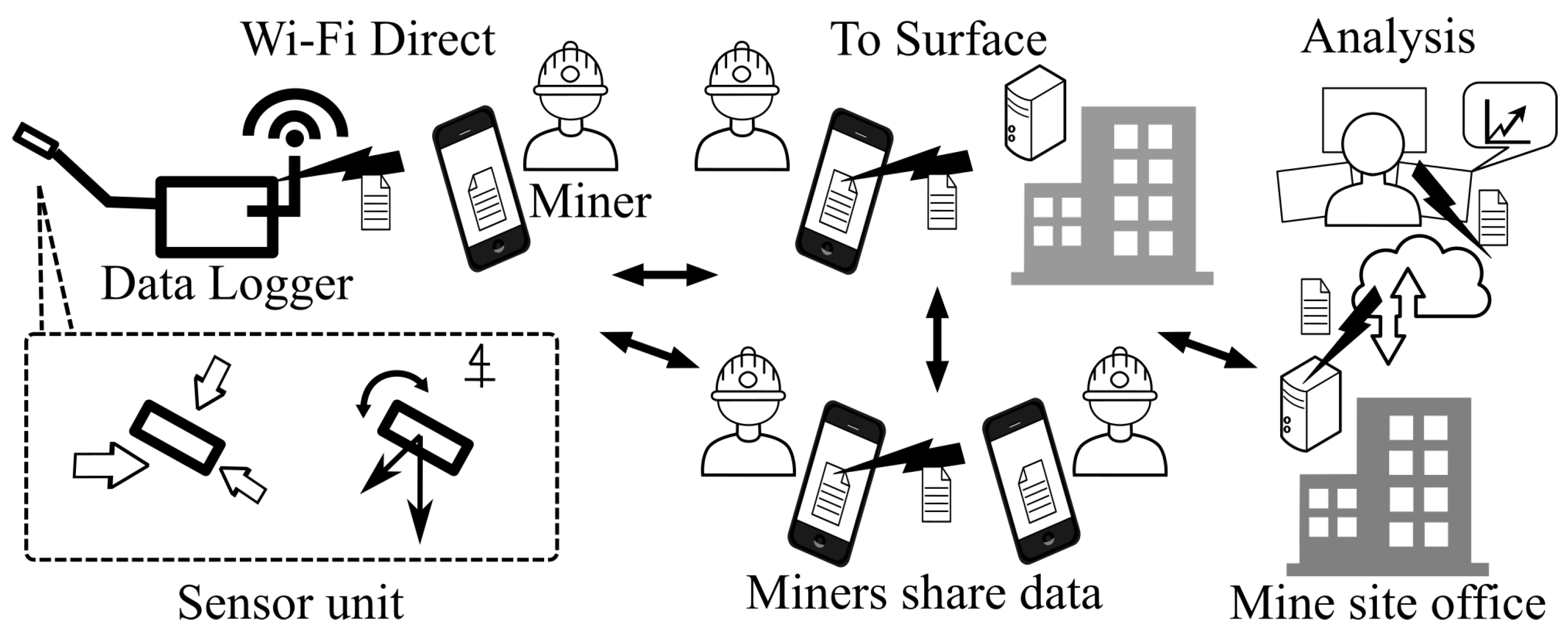
In this study, in situ stress is used as input data. The input data will be sent to the surface and data centre via the proposed communication system, which will be further available in the cloud. The proposed data transfer system design is shown in
Figure 1.
A data logger installed inside an underground mine senses in situ stress, enabling it to be transferred to a mobile device owned by a nearby miner [
36]. Such data can then be sent to another miner’s mobile phone using WiFi Direct. In order to develop a differential in situ stress or strain monitoring system, it is necessary to find a suitable device in the market or to develop a measurement unit (sensing), fulfilling the needs of the experiment, in addition to the communication unit.
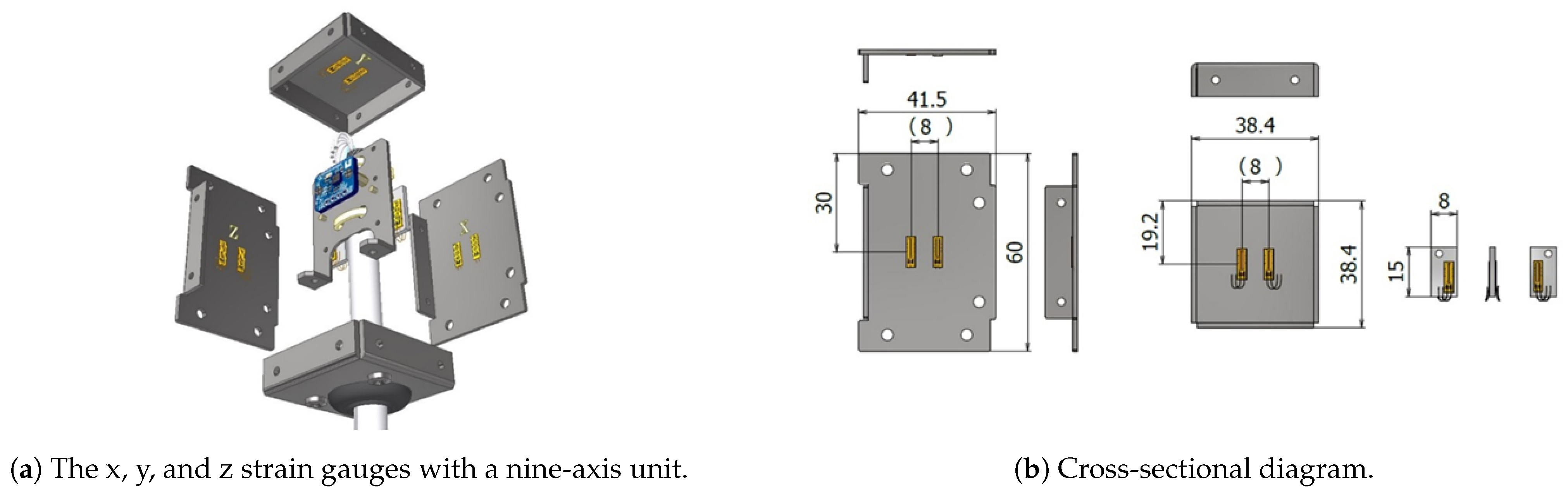
The sensor unit, developed by [
37] can be installed by drilling a hole into the support system of an underground mine with a 60
drill-bit. The computer-aided diagram of the sensor unit is shown in
Figure 2. In
Figure 2a,b the blue-coloured unit, installed close to the centre of the device, is the sensing unit. In addition to a pair of strain gauges attached on the
X,
Y and
Z surface, a nine-axis sensor (LSM9DS1) is installed to detect the orientation of the sensor unit during installation.
Within the sensor unit, each sensor has its advantages and disadvantages. Each sensor’s disadvantages are mutually complemented by its advantages to improve the accuracy of three-dimensional (3D) orientation estimation. Since the stresses measured by the strain gauges are relative to the rock surface, the magnitude and direction of the stresses inside the rock mass are clarified by combining the results of the attitude detection.
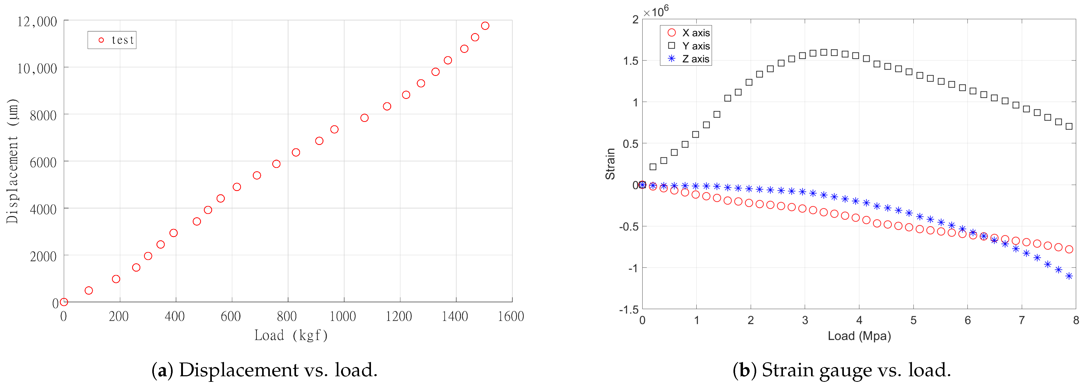
The strain gauges are placed according to the 3D coordinate system (X, Y, Z). The relationship between the strain and stress is determined from the load and displacement of the sensor unit (in situ stress). This can be determined by material testing and the values of the strain gauges. In addition, the in situ differential stress is obtained from the strain applied to the sensor unit in the underground mine.
A load response test was conducted, using Marui’s manual uniaxial compression testing machine (the rated capacity of the load cell is 20 tf) to apply a load to the sensor unit. The load was varied in increments of 50 kgf, and the load-displacement curve (between elastic deformation), the strain, acceleration, angular velocity, and geomagnetism of the sensor unit were collected as the measurement data. The displacements from different load values and strain in the experiments are shown in
Figure 3.
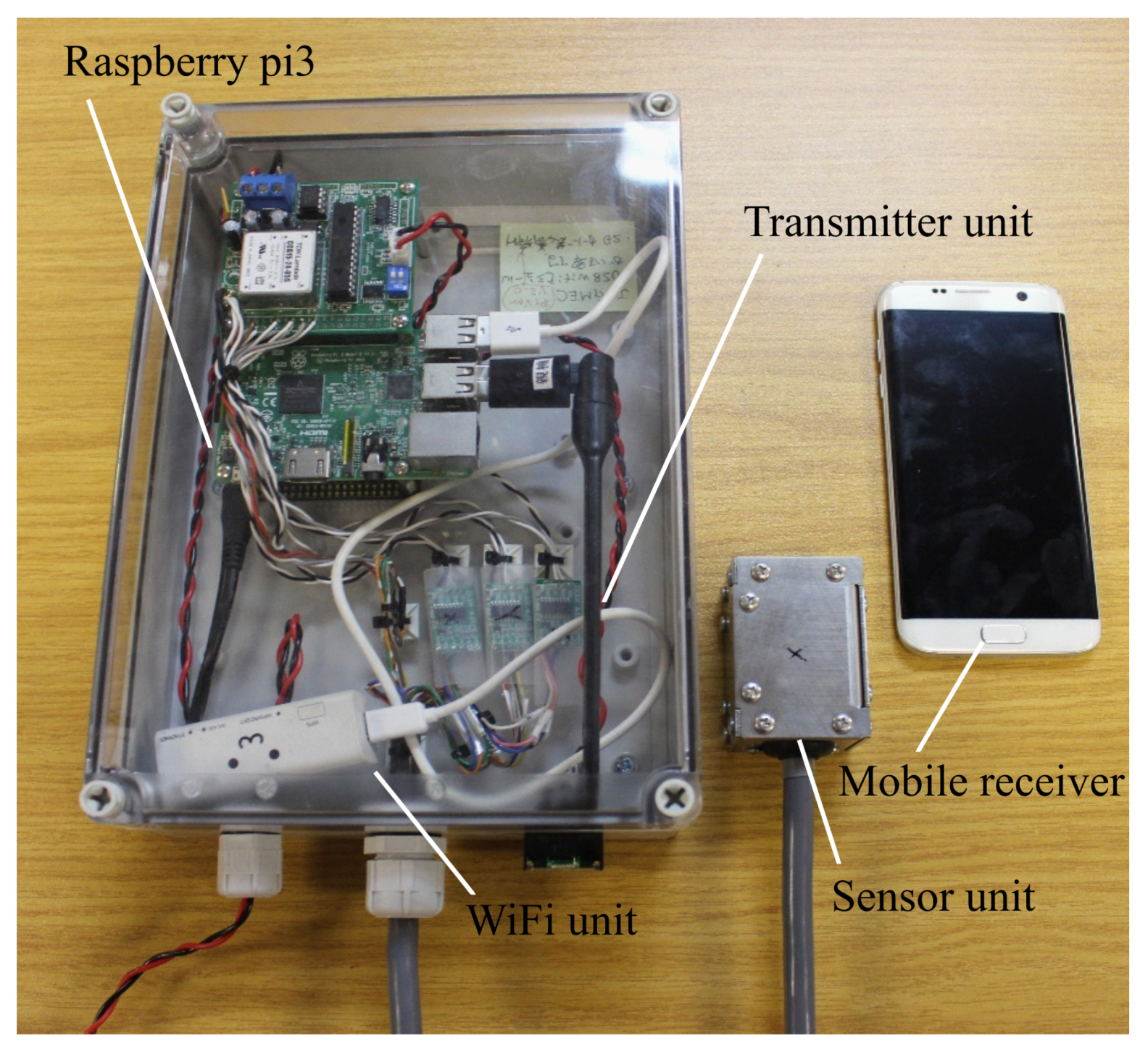
The sampling frequency was set to 1 Hz, and the data were transmitted to the receiver via ad hoc communication (WiFi Direct). In the material test, the load was applied up to 5 MPa in terms of stress. By following the steps above, the possibility of the in situ stress measurement in underground mine via WSN is shown. In situ stress and displacement in the underground mine requires attitude and stress detection of the sensor unit. This enables us to identify the direction and the degree of stress in the underground mine. In
Figure 4, a complete system with integrated the wireless transmitter with the data logger is shown.
4. Received Signal Strength Indicator Model for WiFi Direct
Tunnels in underground mines typically have rough and irregular wall surfaces. The irregularities of the walls influence the scattering, fading, and delay properties of a 2.4 GHz WiFi signal’s propagation. Consider a setup in which a mobile phone is placed at
w meters (m) from a datalogger, placed at a reference position
. The path loss, which follows the normal distribution, is expressed as
in decibels (dB) is used, assuming the antennas used at the transmitter and receiver have unity gain. The average path loss
is measured at the reference position
,
is a constant that describes the path loss exponent, and
N is modelled as Gaussian noise samples having a zero mean and a standard deviation
. From the measured values of
, the values of
and
N can be approximately obtained using the LS regression method for curve-fitting.
5. Experimental Setup
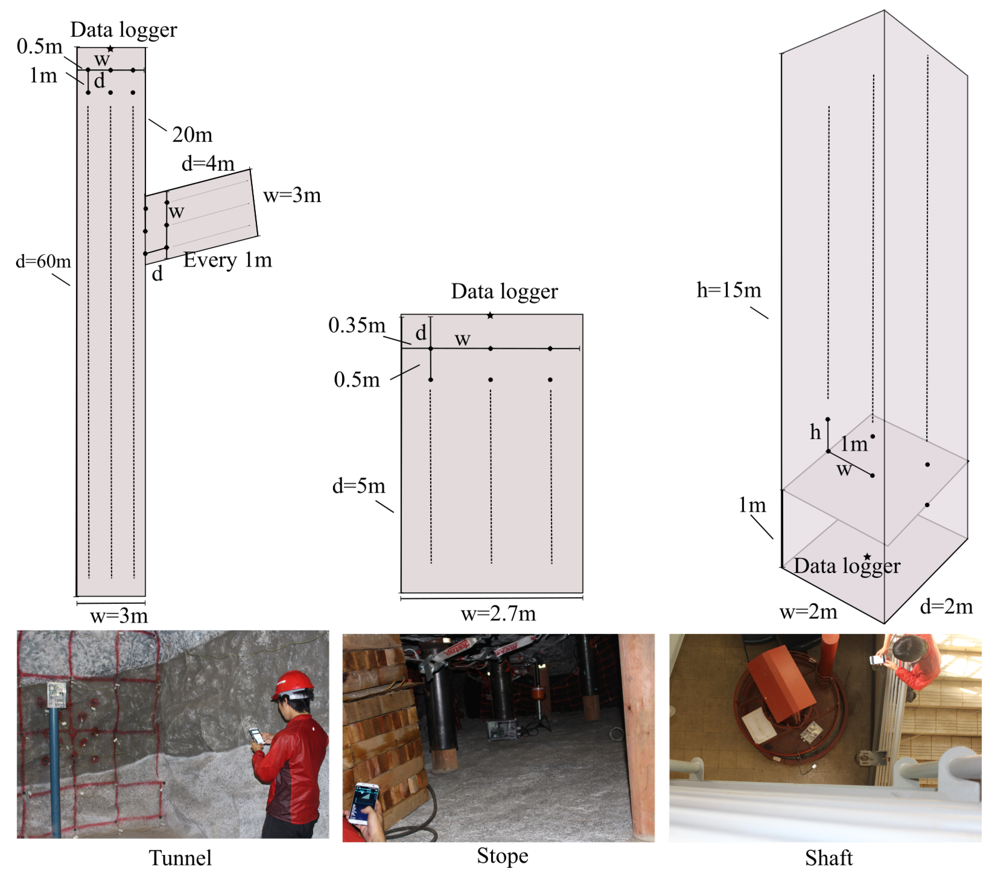
The data collected by the sensor unit is transmitted over a WRH-300WH3-S WiFi module through a Raspberry Pi 3 module. The WRH-300WH3-S unit implements the IEEE 802.11n standard, with a power consumption of 2.4 W. The WiFi receiver is an android operating system mobile device. Measurements are then carried out in a model underground mock mine.
The mine contains a part representing a vertical shaft, tunnel, and narrow-reef stope with the corresponding cross-sections shown in
Figure 5. The dimensions of the measurement areas are defined as (
w,
b,
h), where
w is the width,
b is the length, and
h is the height in meters (m). The position of an object in the measurement areas is described as (
x,
y,
z) in meters, where
x is the horizontal position of the object along the width
w,
y is the horizontal position along the length
b, and
z is the vertical position of the object along the height
h. The dimensions of the tunnel, stope, and shaft are given in
Table 1.
In the tunnel that has a height of 3 m, the sensor along with the transmitter are mounted on a pole and positioned at three different positions, namely (0.5, 0, 1), (1.5, 0, 1), and (2.5, 0, 1). The RSSI is then measured by centering the mobile receiver at position (1.5, y, 1), where m along the tunnel. In the stope, which is 1 m high, the transmitter is positioned at positions (0.35, 0, 0.5), (1.35, 0, 0.5), and (2.35, 0, 0.5), while the transmitter is placed at the floor of the shaft in positions (0, 1, 0), (1, 1, 0), and (2, 1, 0). The receiver is placed at positions (1.35, y, 0.5), m and (1, 1, z), m, respectively.
6. Results and Discussions
Measurements are retrieved in the tunnel, stope and shaft of the mock-up mine test-bed in order to evaluate the RSSI and throughput performance in terms of speed of the WiFi signals over distance. The throughput is the ratio between a size (in megabytes) of a transmitted file and the amount of time (in seconds) that it takes the receiver to download the file. Using the measurements and (
1),
Table 2 shows the path loss coefficients as well as the corresponding variance
of
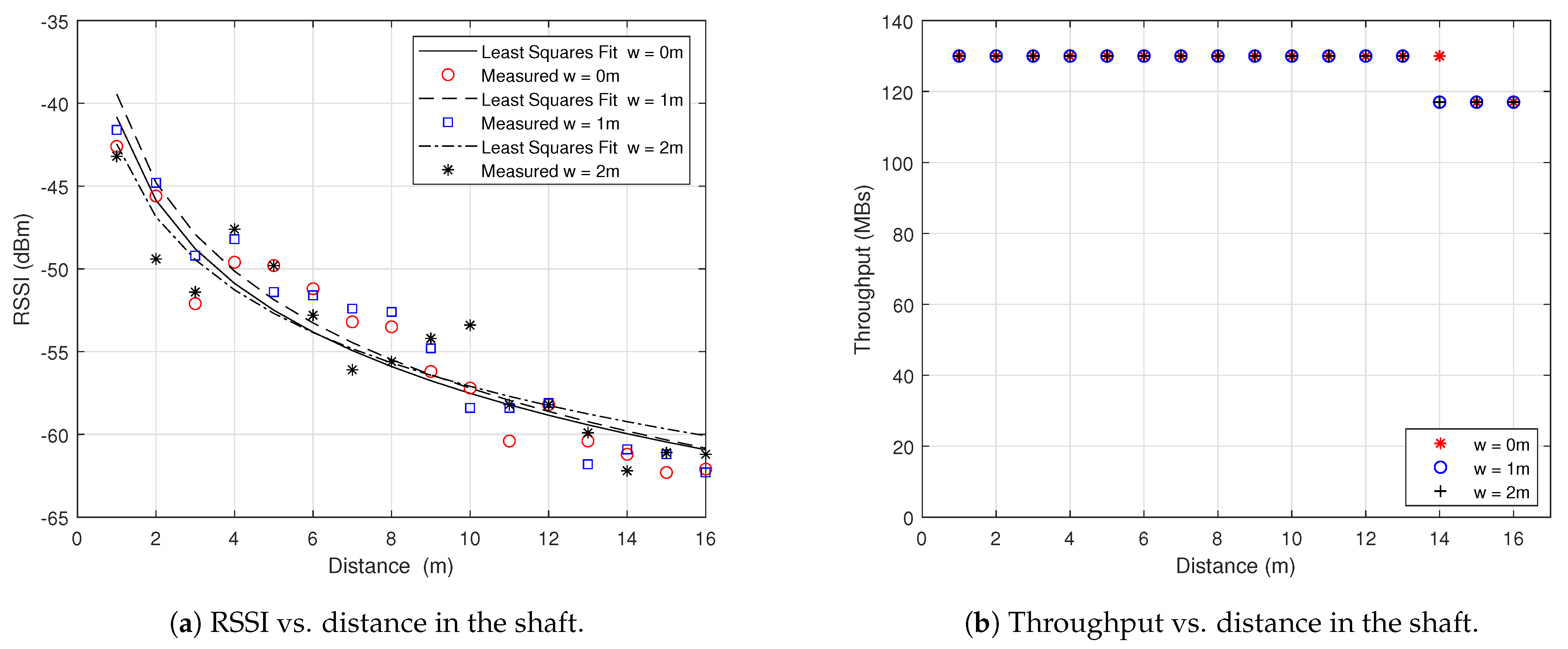
N. The path loss coefficients of the tunnel and shaft are lower than the free space path loss of
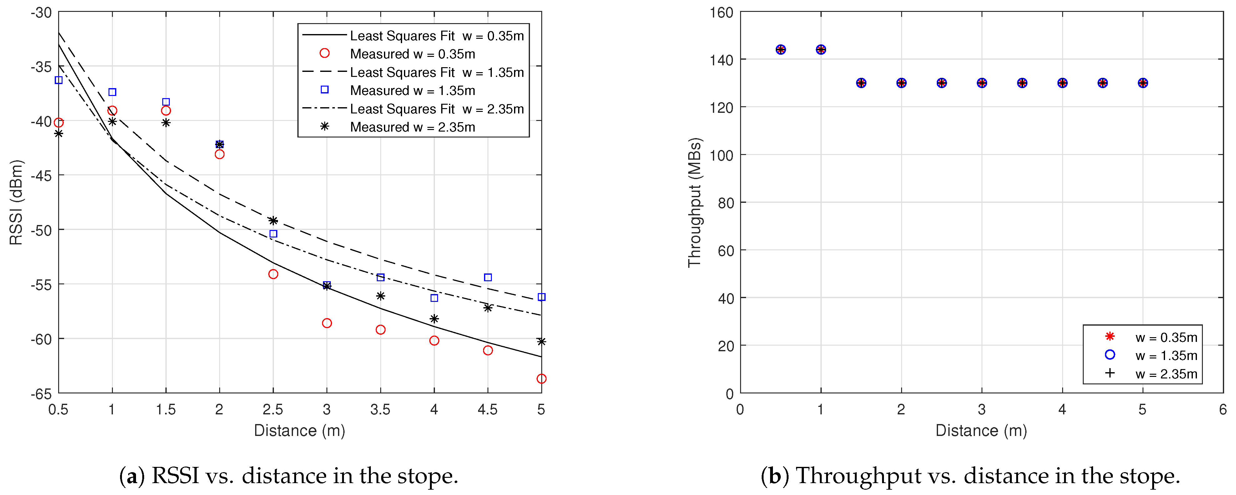
. However, the path loss coefficient of the stope is higher. The stope is narrower and also attenuates signals faster when compared to the tunnel and shaft, according to the
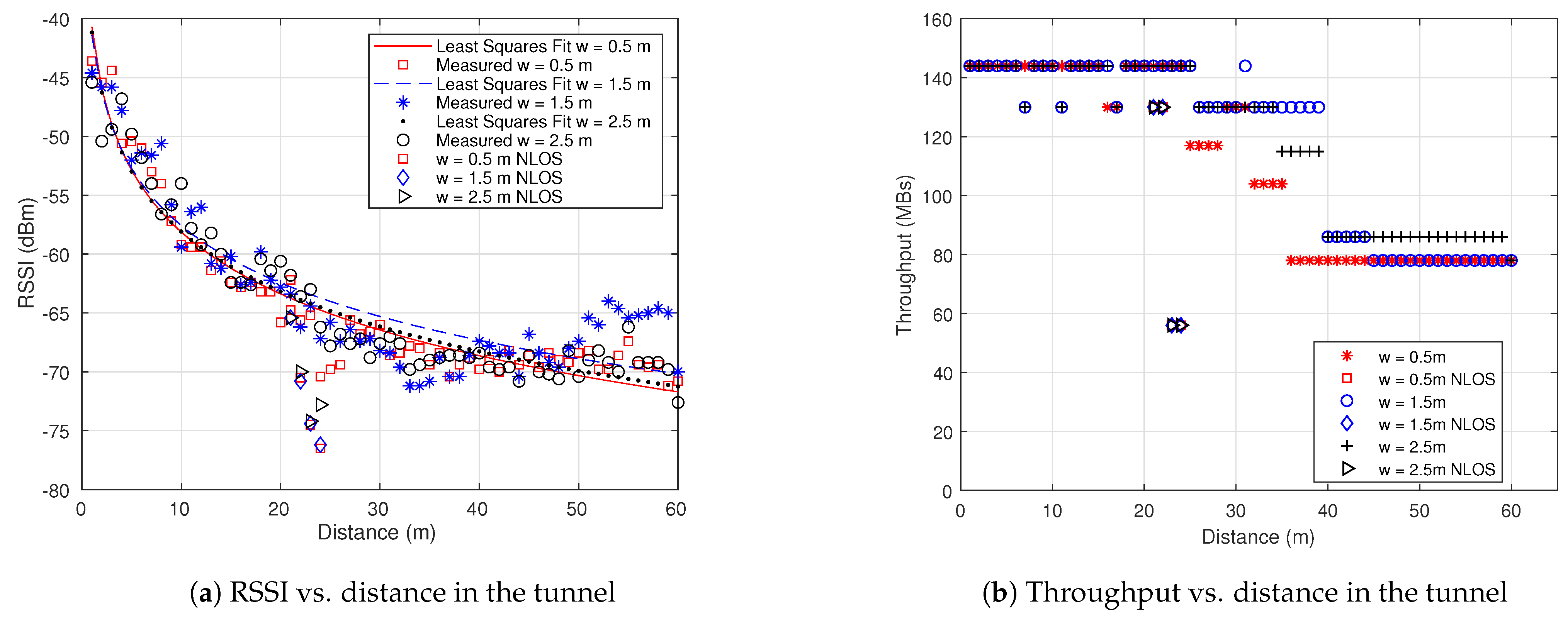
Figure 6a,
Figure 7a and
Figure 8a.
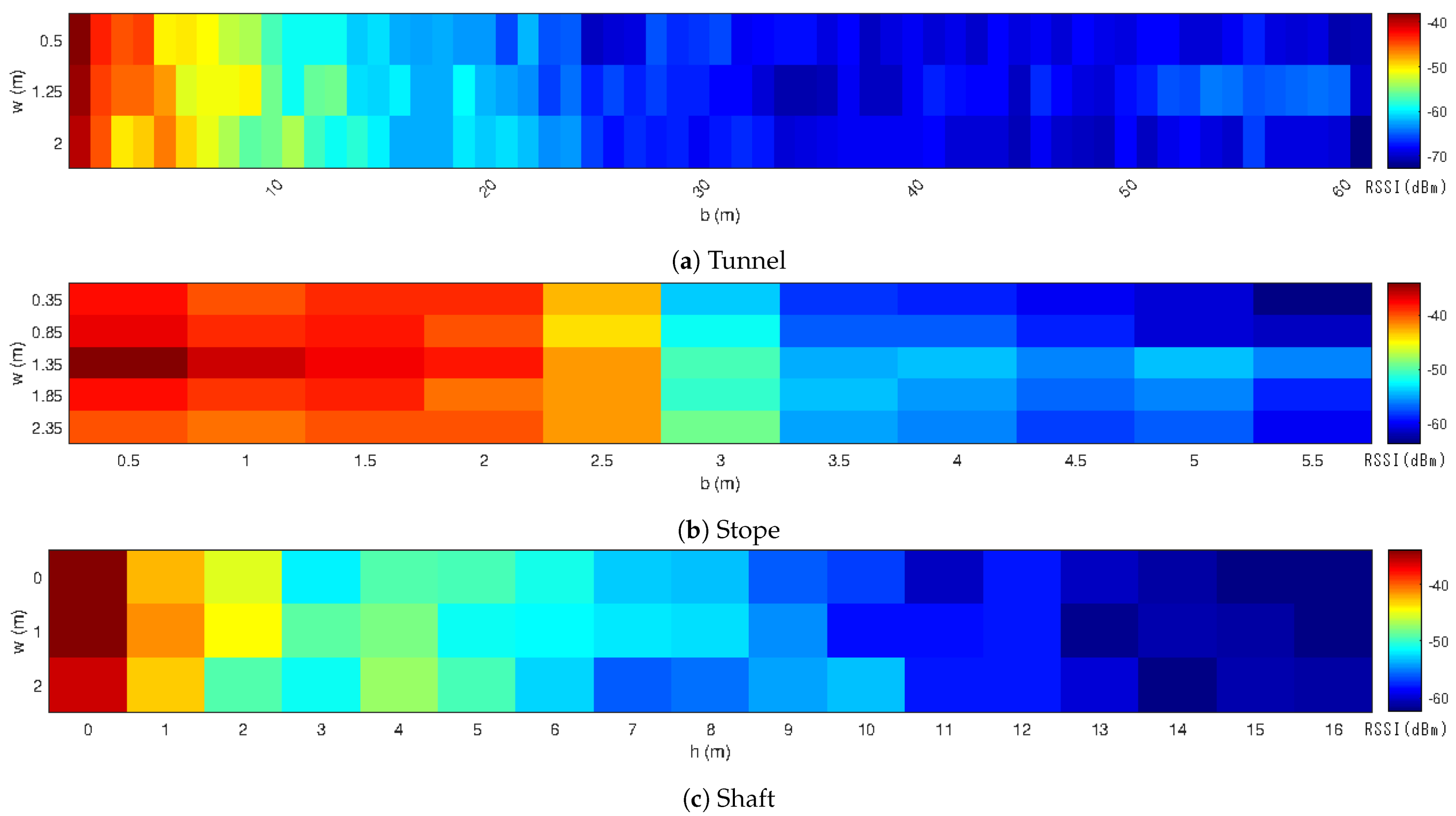
The RSSI over distance is also visualized using heat maps. The colours range from dark blue to dark red, which depicts weak signal strength to strong signal strength, respectively. It is presumed that there is no other radio-emitting equipment in the measurement areas while measurements were taken.
The graph in
Figure 7a shows the sharp decrease in the RSSI values in the stope as compared to the RSSI values in the tunnel and shaft. The stope, however, has stronger RSSI values closer to the transmitter, which can be attributed to constructive reflections due to the more confined area. The tunnel and stope showed different RSSI values at the same distance, and the difference can be attributed to the horizontal measurement of signal propagation in the tunnel and vertical measurements in the shaft.
As observed in
Figure 9a,b, the RSSI values of the transmitter positioned at the edges of the measurement areas show stronger received signal power as the receiver moves away from the transmitter. This is in comparison with the transmitter positioned at the centre of the measurement areas. Furthermore, some regions, such as 54–59 m in the tunnel, show stronger RSSI values compared with the 30–40 m shorter distance. Since the 54–59 m region is closer to the end of the tunnel, which contains steel gates, higher RSSI values in this region may be attributed to multipath reflections in that region.
The heat maps in
Figure 9a–c show more detailed RSSI distributions across the width of the measurement areas. The transmitter was placed in the centre of the width
w of the measurement area, and the RSSI values are obtained along the
w axis every 0.5 m in the tunnel, 1 m in the shaft and 0.35 m in the stope. The throughput was measured in terms of bits transmitted per second or bits per second (bps).
In
Figure 6b,
Figure 7b and
Figure 8b, the throughput drops gradually with distance in most regions, although a sharp drop was observed in some regions in the tunnel. The same throughput of 130 Mbps was observed in all the measurement points in the stope.
Figure 7b showed that high throughput was achievable at lower RSSI values in the stope due to the small area, while the throughput dropped to about half from −63 dBm in the tunnel. Therefore, reliable speed was guaranteed in stope environments to transmit data out of the stope to the next available communication link. Overall, an Mbps communication speed over 60 m was sufficient to communicate important sensor data in real-time. The RSSI values remained above the recommended limit of −80 dBm in all the measurement areas considered.
7. Conclusions
In the near future, underground mines will become deeper and more complex in structure. This necessitates the continuous improvement of worker safety and productivity. One area in which improvements can be made is in communication systems, which are crucial for the safe operation of underground mines, preventing potential accidents and losses from occurring.
Reliable communication is also an important pre-requirement for mechanization and enabler for automation. There is a significant recent body of research on WSN because of its added-value to safety, worker health, improving infrastructure and general efficiency in mining.
In this study, the practical communication of critical sensor data in three underground mining environments was demonstrated and analyzed using the RSS. According to the experimental results, a communication speed of Mbps at a distance of 60 m was sufficient for real-time communication of important sensor data. In addition, the recommended RSSI value to maintain was −80 dBm in all measurement areas. The statistical properties of the path loss associated with the measurement environments were derived. In addition, this communication system does not require a central access point.
Communication is, therefore, possible, not only from the base unit to the mobile terminal but also from the mobile terminal to other mobile terminals. Hence, the signal strength information can influence the placements of the signal repeaters for longer distance transmissions. Furthermore, the communication speed observed from the measurements indicates that high data rate applications can be supported. More than 70 Mbps is possible in LOS environments, while the speed drops to over 50 Mbps in NLOS environments.
Author Contributions
Conceptualization, H.I. and F.T.C.; Data curation, H.I., O.K. and M.A.M.; Funding acquisition, Y.K.; Investigation, H.I. and F.T.C.; Methodology, H.I., O.K. and F.T.C.; Project administration, F.T.C. and Y.K.; Resources, O.K.; Software, H.I., O.K. and M.A.M.; Supervision, Y.K.; Visualization, O.K. and M.A.M.; Writing—original draft, H.I. and F.T.C.; Writing—review & editing, H.I., O.K. and Y.K. All authors have read and agreed to the published version of the manuscript.
Funding
United Nations University provided financial support for this research as a member of the Global Leadership Training Program (GLTP) 2019.
Data Availability Statement
Not applicable.
Acknowledgments
The authors would like to thank and acknowledge the experimental support provided by the Sibanye-Stillwater Digital Mining Laboratory (DigiMine), South Africa, Wits Mining Institute (WMI), South Africa, University of the Witwatersrand, Johannesburg, South Africa. Japan Society for the Promotion of Science (JSPS) provided financial support for this research as a Grant-in-Aid for JSPS Research Fellow; Grant Number JP21J15181.The Ministry of Education, Culture, Sports, Science and Technology (MEXT) provided financial support for this research as an Inter-University Exchange Project “Akita University/Kyushu University An innovative program for development of core human resources for smart mining to lead sustainable resource development in Southern Africa”.
Conflicts of Interest
The authors declare no conflict of interest.
References
- Kolade, O.; Cheng, L. Markov Model Characterization of a Multicarrier Narrowband Powerline Channel With Memory in an Underground Mining Environment. IEEE Access 2021, 9, 59085–59092. [Google Scholar] [CrossRef]
- Kolade, O.; Familua, A.D.; Cheng, L. Channel models for an indoor power line communication system. IET-Commun. Technol. Netw. Smart Cities 2021, 90, 67. [Google Scholar]
- Dohare, Y.S.; Maity, T.; Das, P.S.; Paul, P.S. Wireless communication and environment monitoring in underground coal mines–review. IETE Tech. Rev. 2015, 32, 140–150. [Google Scholar] [CrossRef]
- Singh, A.; Singh, U.K.; Kumar, D. IoT in mining for sensing, monitoring and prediction of underground mines roof support. In Proceedings of the 2018 4th International Conference on Recent Advances in Information Technology (RAIT), Dhanbad, India, 15–17 March 2018; pp. 1–5. [Google Scholar]
- Bhattacharjee, S.; Roy, P.; Ghosh, S.; Misra, S.; Obaidat, M.S. Wireless sensor network-based fire detection, alarming, monitoring and prevention system for Bord-and-Pillar coal mines. J. Syst. Softw. 2012, 85, 571–581. [Google Scholar] [CrossRef]
- Misra, P.; Kanhere, S.; Ostry, D.; Jha, S. Safety assurance and rescue communication systems in high-stress environments: A mining case study. IEEE Commun. Mag. 2010, 48, 66–73. [Google Scholar] [CrossRef]
- Qin, X.; Fu, M.; Shen, B. Coal mine gas wireless monitoring system based on WSNs. In Proceedings of the 2011 Second International Conference on Digital Manufacturing & Automation, Zhangjiajie, China, 5–7 August 2011; pp. 309–312. [Google Scholar]
- Kang, H.; Zhang, X.; Si, L.; Wu, Y.; Gao, F. In-Situ stress measurements and stress distribution characteristics in underground coal mines in China. Eng. Geol. 2010, 116, 333–345. [Google Scholar] [CrossRef]
- Xia, K.; Chen, C.; Deng, Y.; Xiao, G.; Zheng, Y.; Liu, X.; Fu, H.; Song, X.; Chen, L. In Situ monitoring and analysis of the mining-induced deep ground movement in a metal mine. Int. J. Rock Mech. Min. Sci. 2018, 109, 32–51. [Google Scholar] [CrossRef]
- Abdalzaher, M.S.; Samy, L.; Muta, O. Non-zero-sum game-based trust model to enhance wireless sensor networks security for IoT applications. Inst. Eng. Technol. Wirel. Sens. Syst. 2019, 9, 218–226. [Google Scholar] [CrossRef]
- Abdalzaher, M.S.; Muta, O. A Game-Theoretic Approach for Enhancing Security and Data Trustworthiness in IoT Applications. IEEE Internet Things J. 2020, 7, 11250–11261. [Google Scholar] [CrossRef]
- Abdalzaher, M.S.; Seddik, K.; Muta, O. An effective Stackelberg game for high-assurance of data trustworthiness in WSNs. In Proceedings of the 2017 IEEE Symposium on Computers and Communications (ISCC), Heraklion, Greece, 3–6 July 2017; pp. 1257–1262. [Google Scholar]
- Fang, L.; Ge, C.; Zu, G.; Wang, X.; Ding, W.; Xiao, C.; Zhao, L. A Mobile Edge Computing Architecture for Safety in Mining Industry. In Proceedings of the 2019 IEEE SmartWorld, Ubiquitous Intelligence & Computing, Advanced & Trusted Computing, Scalable Computing & Communications, Cloud & Big Data Computing, Internet of People and Smart City Innovation (SmartWorld/SCALCOM/UIC/ATC/CBDCom/IOP/SCI), Leicester, UK, 19–23 August 2019; pp. 1494–1498. [Google Scholar]
- Zhang, Y.; Zhao, L.; Yang, K.; Xu, L. Mobile Edge Computing for Intelligent Mining Safety: A Case Study of Ventilator. In Proceedings of the 2020 IEEE International Conference on Parallel & Distributed Processing with Applications, Big Data & Cloud Computing, Sustainable Computing & Communications, Social Computing & Networking (ISPA/BDCloud/SocialCom/SustainCom), Exeter, UK, 17–19 December 2020; pp. 1300–1305. [Google Scholar]
- Forooshani, A.E.; Bashir, S.; Michelson, D.G.; Noghanian, S. A survey of wireless communications and propagation modeling in underground mines. IEEE Commun. Surv. Tutor. 2013, 15, 1524–1545. [Google Scholar] [CrossRef]
- Zhang, Y.; Yang, W.; Han, D.; Kim, Y. An integrated environment monitoring system for underground coal mines-Wireless Sensor Network subsystem with multi-parameter monitoring. Sensors 2014, 14, 13149–13170. [Google Scholar] [CrossRef] [PubMed] [Green Version]
- Kawamura, Y.; Dewan, A.M.; Veenendaal, B.; Hayashi, M.; Shibuya, T.; Kitahara, I.; Nobuhara, H.; Ishii, K. Using GIS to develop a mobile communications network for disaster-damaged areas. Int. J. Digit. Earth 2014, 7, 279–293. [Google Scholar] [CrossRef]
- Moridi, M.A.; Kawamura, Y.; Sharifzadeh, M.; Chanda, E.K.; Wagner, M.; Okawa, H. Performance analysis of ZigBee network topologies for underground space monitoring and communication systems. Tunneling Undergr. Space Technol. 2018, 71, 201–209. [Google Scholar] [CrossRef]
- Moridi, M.A.; Kawamura, Y.; Sharifzadeh, M.; Chanda, E.K.; Wagner, M.; Jang, H.; Okawa, H. Development of underground mine monitoring and communication system integrated ZigBee and GIS. Int. J. Min. Sci. Technol. 2015, 25, 811–818. [Google Scholar] [CrossRef] [Green Version]
- Moridi, M.A.; Kawamura, Y.; Sharifzadeh, M.; Chanda, E.K.; Jang, H. An investigation of underground monitoring and communication system based on radio waves attenuation using ZigBee. Tunneling Undergr. Space Technol. 2014, 43, 362–369. [Google Scholar] [CrossRef]
- Moridi, M.A.; Sharifzadeh, M.; Kawamura, Y.; Jang, H.D. Development of wireless sensor networks for underground communication and monitoring systems (the cases of underground mine environments). Tunneling Undergr. Space Technol. 2018, 73, 127–138. [Google Scholar] [CrossRef] [Green Version]
- Tao, P.; Xiaoyang, L. Hybrid wireless communication system using ZigBee and WiFi technology in the coal mine tunnels. In Proceedings of the 2011 Third International Conference on Measuring Technology and Mechatronics Automation, Shanghai, China, 6–7 January 2011; Volume 2, pp. 340–343. [Google Scholar]
- Rappaport, T.S. Wireless Communications: Principles and Practice; Prentice Hall PTR: Hoboken, NJ, USA, 1996; Volume 2. [Google Scholar]
- Blumrosen, G.; Hod, B.; Anker, T.; Dolev, D.; Rubinsky, B. Enhanced calibration technique for RSSI-based ranging in body area networks. Ad. Hoc. Netw. 2013, 11, 555–569. [Google Scholar] [CrossRef]
- Bullmann, M.; Fetzer, T.; Ebner, F.; Ebner, M.; Deinzer, F.; Grzegorzek, M. Comparison of 2.4 GHz WiFi FTM-and RSSI-Based indoor positioning methods in realistic scenarios. Sensors 2020, 20, 4515. [Google Scholar] [CrossRef]
- Qian, J.; Song, M. Research and application of underground WLAN adaptive radio fingerprint database. Sensors 2020, 20, 1182. [Google Scholar] [CrossRef] [Green Version]
- Rana, S.P.; Prieto, J.; Dey, M.; Dudley, S.; Corchado, J.M. A self regulating and crowdsourced indoor positioning system through Wi-Fi fingerprinting for multi storey buildings. Sensors 2018, 18, 3766. [Google Scholar] [CrossRef] [Green Version]
- Shi, Y.; Zhang, W.; Yao, Z.; Li, M.; Liang, Z.; Cao, Z.; Zhang, H.; Huang, Q. Design of a hybrid indoor location system based on multi-sensor fusion for robot navigation. Sensors 2018, 18, 3581. [Google Scholar] [CrossRef] [Green Version]
- Ebner, F.; Fetzer, T.; Deinzer, F.; Grzegorzek, M. On Wi-Fi model optimizations for smartphone-based indoor localization. ISPRS Int. J. Geo-Inf. 2017, 6, 233. [Google Scholar] [CrossRef] [Green Version]
- Pei, L.; Liu, J.; Chen, Y.; Chen, R.; Chen, L. Evaluation of fingerprinting-based WiFi indoor localization coexisted with Bluetooth. J. Glob. Position. Syst. 2017, 15, 1–12. [Google Scholar] [CrossRef] [Green Version]
- Bahl, P.; Padmanabhan, V.N. RADAR: An in-building RF-based user location and tracking system. In Proceedings of the Proceedings IEEE INFOCOM 2000. Conference on Computer Communications. Nineteenth Annual Joint Conference of the IEEE Computer and Communications Societies (Cat. No.00CH37064), Tel Aviv, Israel, 26–30 March 2000; Volume 2, pp. 775–784. [Google Scholar]
- Li, H.; Chen, L. RSSI-Aware energy saving for large file downloading on smartphones. IEEE Embed. Syst. Lett. 2015, 7, 63–66. [Google Scholar] [CrossRef]
- Emslie, A.; Lagace, R.; Strong, P. Theory of the propagation of UHF radio waves in coal mine tunnels. IEEE Trans. Antennas Propag. 1975, 23, 192–205. [Google Scholar] [CrossRef] [Green Version]
- Zhang, Y.P.; Zheng, G.X.; Sheng, J.X. Radio propagation at 900 MHz in underground coal mines. Antennas and Propagation. IEEE Trans. Antennas Propag. 2001, 49, 757–762. [Google Scholar] [CrossRef]
- Boutin, M.; Benzakour, A.; Despins, C.L.; Affes, S. Radio wave characterization and modeling in underground mine tunnels. IEEE Trans. Antennas Propag. 2008, 56, 540–549. [Google Scholar] [CrossRef]
- Ikeda, H.; Kawamura, Y.; Tungol, Z.; Moridi, M.A.; Jang, H. Implementation and verification of a Wi-Fi Ad Hoc communication system in an underground mine environment. J. Min. Sci. 2019, 55, 505–514. [Google Scholar] [CrossRef]
- Ikeda, H.; Kawamura, Y.; Jang, H.D.; Mokhtar, N.; Yokokura, J.; Tungol, Z. Development of an underground in situ stress monitoring system for mining safety using multi sensor cell and Wi-Fi Direct technology. In International Symposium on Mine Planning and Equipment Selection; Springer: Cham, Switzerland, 2019; pp. 236–244. [Google Scholar]
| Publisher’s Note: MDPI stays neutral with regard to jurisdictional claims in published maps and institutional affiliations. |
© 2021 by the authors. Licensee MDPI, Basel, Switzerland. This article is an open access article distributed under the terms and conditions of the Creative Commons Attribution (CC BY) license (https://creativecommons.org/licenses/by/4.0/).


 ,
, 


