
DMRB Flexible Road Pavement Design Using Re-Engineered Expansive Road Subgrade Materials with Varying Plasticity Index


Abstract
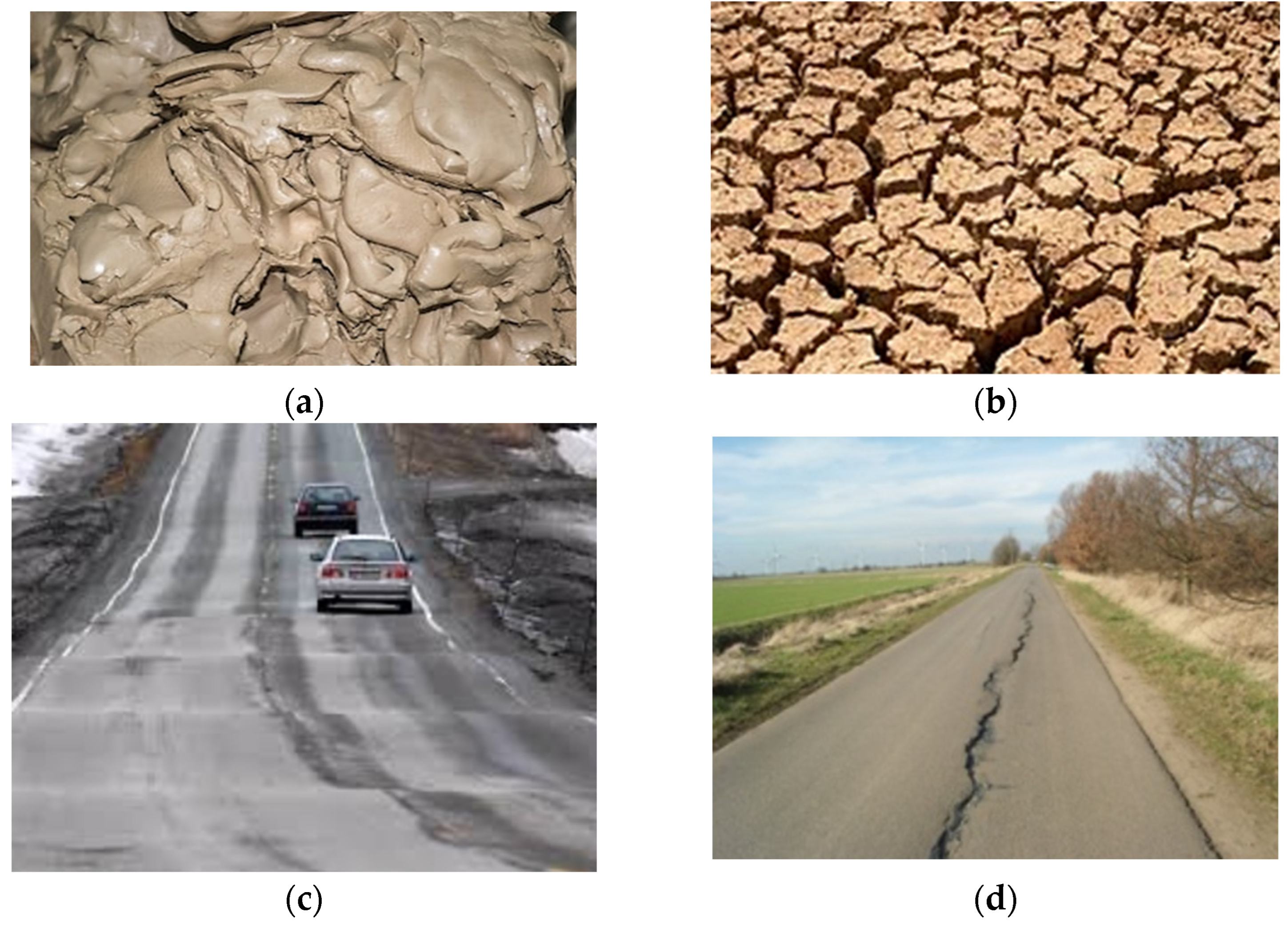
:1. Introduction
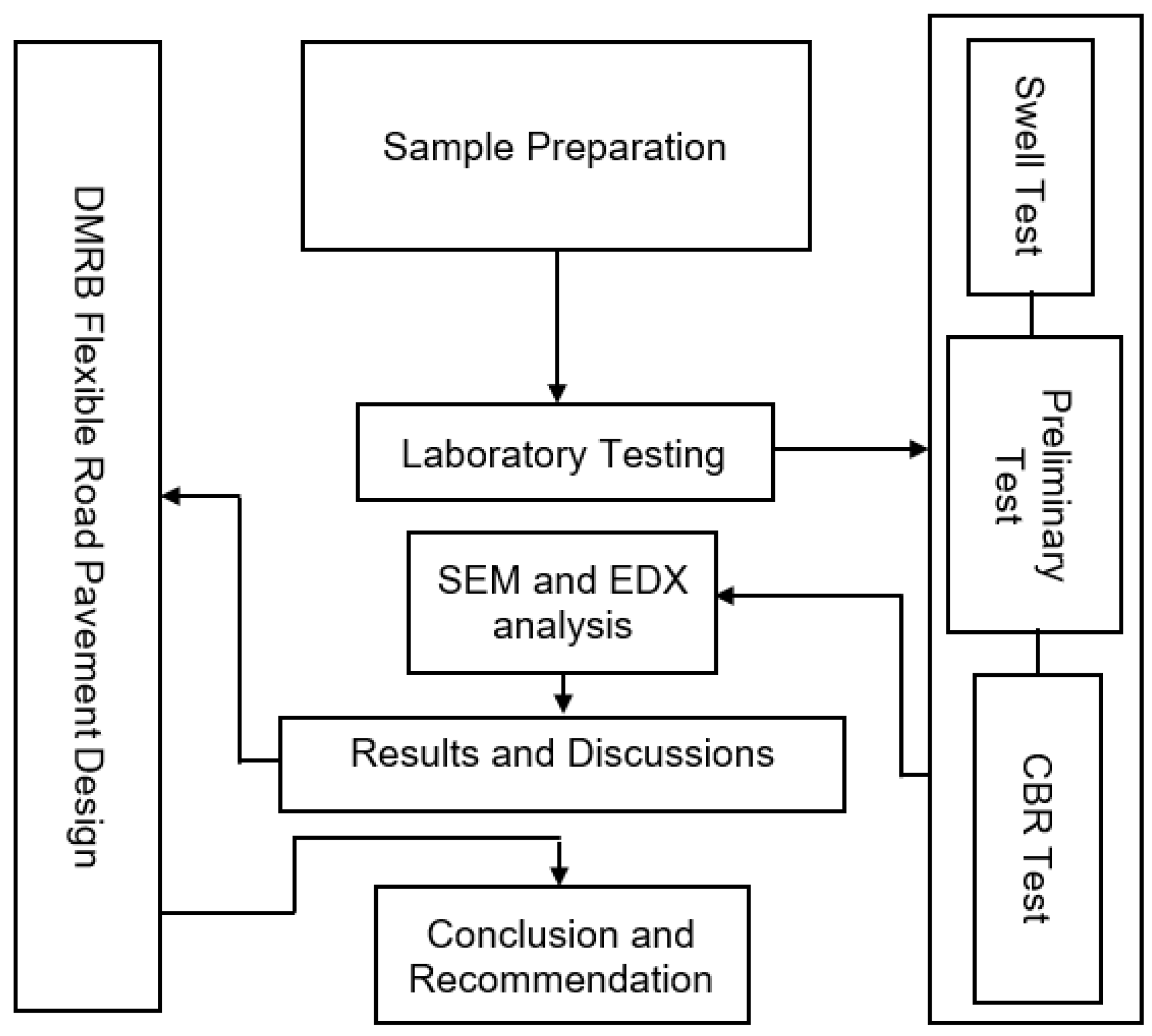
2. Materials and Methods
3. Results and Discussion
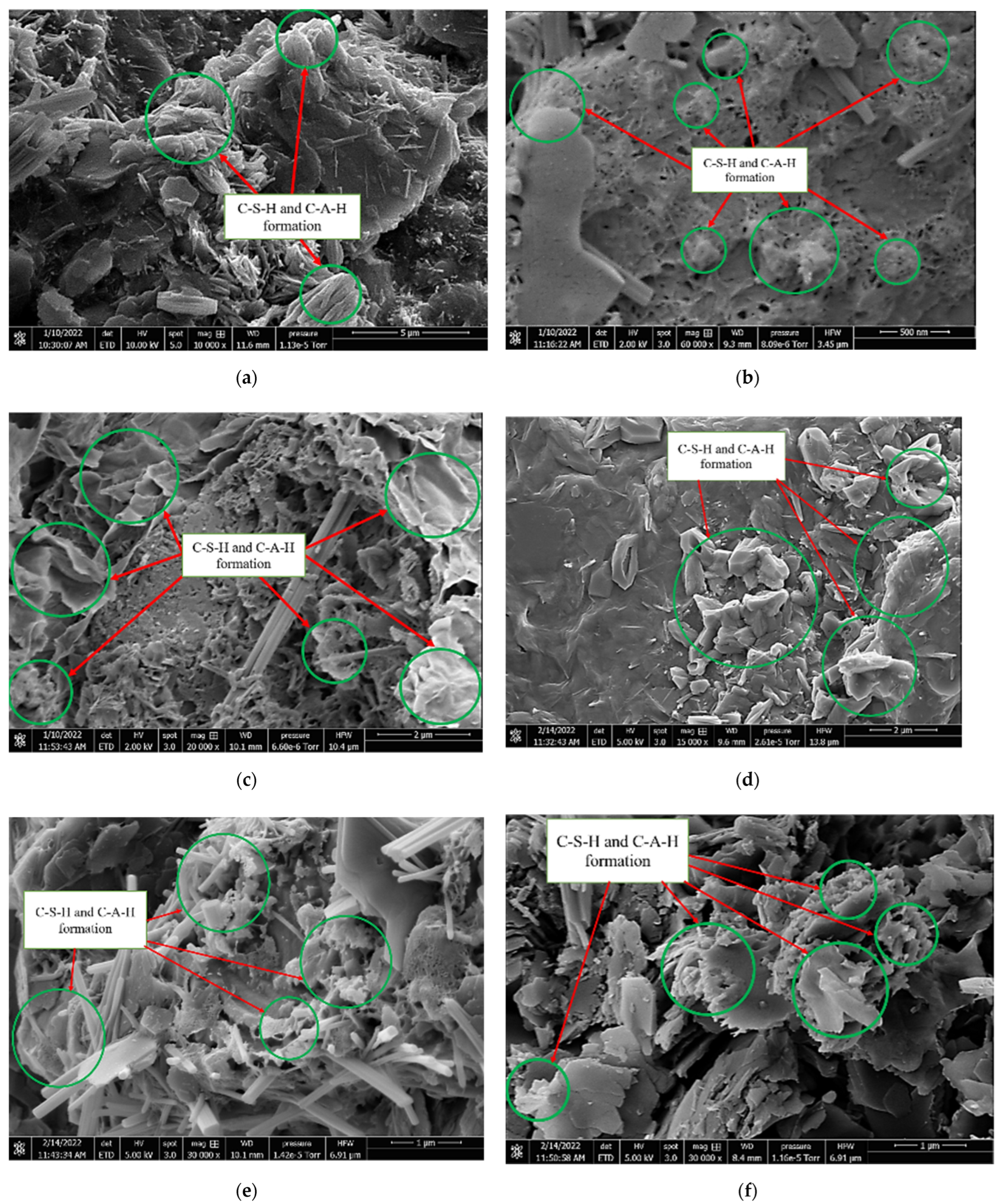
Californa Bearing Ratio (CBR) and Microstructural Characteristics
4. DMRB Road Pavement Design
5. Conclusions
- There was no significant difference in pavement thickness for low and high CBR values when using DMRB in road pavement design. A significant change in pavement thickness can only be observed for subgrade CBR values from 2–5% when using DMRB in road pavement design. CBR values and elastic modulus influenced the overall thickness of road pavement.
- This study would benefit the industry in many ways, as road contractors can quickly refer to this study to determine road pavement layer thickness when they encounter subgrade materials with CBR characteristics similar to what was used in this study.
- ASS samples with high bentonite content recorded a high plasticity index with unacceptable swell values greater than 2.5% and acceptable CBR values below 2%.
- Lime and cement were able to improve the engineering properties of ASS materials and reduce swell to the lowest minimum of 0.04%
- CBR value increased with an increase in bentonite content in treated and untreated ASS samples. This proves that bentonite has a high bearing capacity.
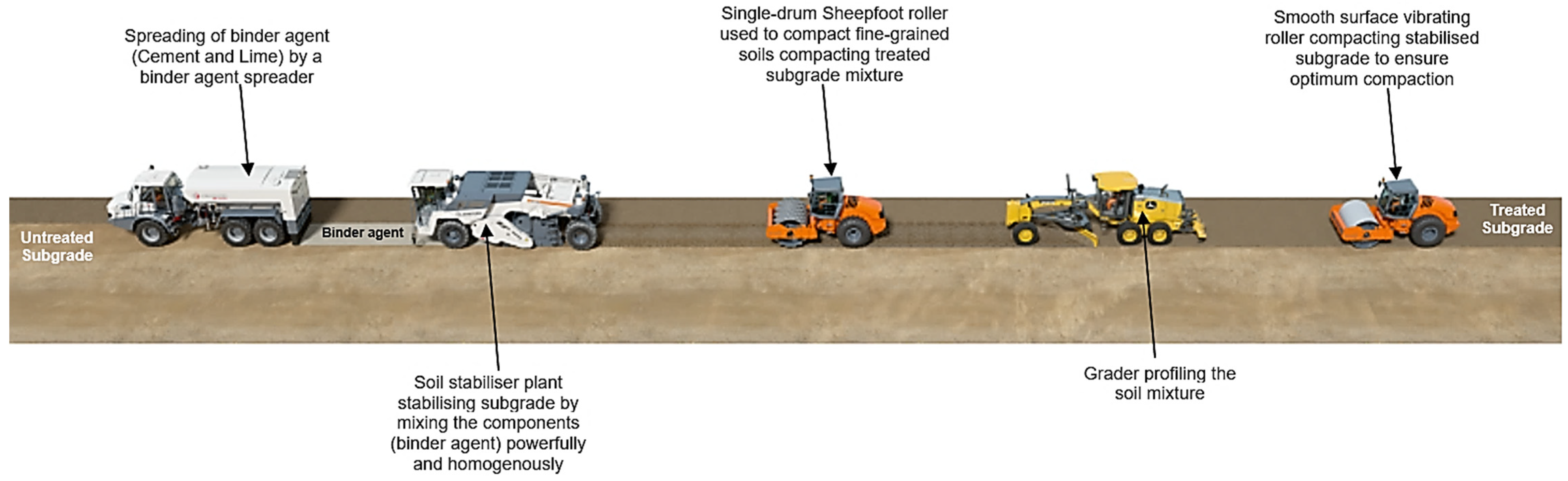
- Based on the finding in this study, it is recommended that subgrade materials are stabilised on-site to reduce the cost of construction instead of removing them and replacing them with imported materials.
Author Contributions
Funding
Institutional Review Board Statement
Informed Consent Statement
Data Availability Statement
Acknowledgments
Conflicts of Interest
References
- Paul, A. Pavement Design in Road Construction—Design Parameters. 2014. Available online: https://civildigital.com/pavement-design-road-construction-design-parameters/ (accessed on 11 March 2022).
- Wilson, S. Whole Life Cycle Cost Analysis for various Pavement and Drainage Options; Interpave—The Precast Concrete Paving and Kerb Association, a Product Association of BPCF Ltd.: Glenfield, UK, 2006. [Google Scholar]
- Amakye, S.Y.; Abbey, S.J. Understanding the performance of expansive subgrade materials treated with non-traditional stabilisers: A Review. Clean. Eng. Technol. 2021, 4, 100159. [Google Scholar] [CrossRef]
- Amakye, S.Y.; Abbey, S.J.; Booth, C.A.; Mahamadu, A. Enhancing the engineering properties of subgrade materials using processed waste: A review. Geotechnics 2021, 1, 0015. [Google Scholar] [CrossRef]
- Li, J.; Cameron, D.A.; Ren, G. Case study and back analysis of a residential building damaged by expansive soils. Comput. Geotech. 2014, 56, 89–99. [Google Scholar] [CrossRef] [Green Version]
- Jones, L.D.; Jefferson, I. Institution of Civil Engineers Manuals Series. 2019. Available online: http://nora.nerc.ac.uk/id/eprint/17002/1/C5_expansive_soils_Oct.pdf (accessed on 29 November 2021).
- López-Lara, T.; Hernández-Zaragoza, J.; Horta-Rangel, J.; Rojas-González, E.; López-Ayala, S.; Castaño, V. Expansion reduction of clayey soils through Surcharge application and Lime Treatment. Case Stud. 2017, 7, 102–109. [Google Scholar] [CrossRef]
- Neville, A.M. Properties of Concrete 5th Edition. New York, NY: Harlow, England. 2011. Available online: https://pdfcoffee.com/properties-of-concrete-fifth-edition-a-m-neville-pdf-pdf-free.html (accessed on 2 October 2021).
- Walker, P. Review and Experimental Comparison of erosion tests or Earth Blocks. In Proceedings of the 8th International Conference on the Study and Conservation of Earthen Architecture, Torquay, UK, May 2000; James & James: London, UK, 2000. [Google Scholar]
- Gooding, D.E.; Thomas, T.H. The Potential of Cement Stabilised or Treated Building Blocks as an Urban Building Material in Developing Countries. DTU Working Paper No.44. 1995. 2021. Available online: https://warwick.ac.uk/fac/sci/eng/research/grouplist/structural/dtu/pubs/wp/wp44/wp44_.pdf (accessed on 18 November 2021).
- Abbey, S.J.; Ngambi, S.; Olubanwo, A.O.; Tetteh, F.K. Strength and Hydraulic Conductivity of Cement and By-Product Cementitious Materials Improved Soil. Int. J. Appl. Eng. Res. 2018, 13, 8684–8694. [Google Scholar]
- Boardman, D.I.; Glendinning, S.; Rogers, C.D.F. Development of stabilisation and solidification in lime-clay mixes. Geotechnique 2001, 51, 533–543. [Google Scholar] [CrossRef]
- Ingles, O.G.; Metcalf, J.B. Soil Stabilisation; Butterworth Pty, Ltd.: Sydney, Australia, 1972. [Google Scholar]
- Ingles, O.H. Soil stabilisation. Chapter 38. In Ground Engineer’s Reference Book; Bell, F.G., Ed.; Butterworths: London, UK, 1987; pp. 38/1–38/26. [Google Scholar]
- Amakye, S.Y.O.; Abbey, S.J.; Booth, C.A.; Oti, J. Road Pavement Thickness and Construction Depth Optimization Using Treated and Untreated Artificially-Synthesized Expansive Road Subgrade Materials with Varying Plasticity Index. Materials 2022, 15, 2773. [Google Scholar] [CrossRef] [PubMed]
- British Standard, BS 1924-1:2018; Stabilised or Treated Materials for Civil Engineering Purposes. Available online: https://0-www-bsigroup-com.brum.beds.ac.uk/en-GB/ (accessed on 7 May 2022).
- Design Manual for Roads and Bridges (DMRB) CD 226; Design for New Pavement Construction. Available online: https://www.standardsforhighways.co.uk/ha/standards/ (accessed on 7 May 2022).
- Design Manual for Roads and Bridges DMRB HD 26/06; Pavement Design. Available online: https://pdf4pro.com/amp/view/hd-26-06-pavement-design-standards-for-highways-3ef7c2.html (accessed on 7 May 2022).
- Interim Advice Note (IAN) 73/06; Design Guidance for Road Pavement Foundations. Available online: http://origin.standardsforhighways.co.uk/ha/standards/ians/pdfs/ian73.pdf (accessed on 7 May 2022).
- British Standard, BS EN 13286-2-2012; Unbound and Hydraulically Bound Mixtures—Test Methods for Laboratory Reference Density and Water Content. Proctor Compaction. Available online: https://www.thenbs.com/PublicationIndex/Documents/Details?DocId=311925 (accessed on 7 May 2022).
- British Standard, BS EN ISO 17892-12-2021; Geotechnical Investigation and Testing. Laboratory Testing of Soil—Determination of Water Content. Available online: https://0-standardsdevelopment-bsigroup-com.brum.beds.ac.uk/projects/2020-00948#/section (accessed on 7 May 2022).
- British Standard, BS 1377- 4:1990; Methods of Test for Soils for Civil Engineering Purposes—Compaction—Related Tests. Available online: https://www.thenbs.com/PublicationIndex/documents/details?Pub=BSI&DocID=261911 (accessed on 7 May 2022).
- AASHTO T265; Standard Method of Test for Laboratory Determination of Moisture Content of Soils. 2015. Available online: https://www.transportation.org/ (accessed on 7 May 2022).
- ASTM D2216-19; 2019. Standard Test Methods for Laboratory Determination of Water (Moisture) Content of Soil and Rock by Mass. Available online: https://www.astm.org/d2216-19.html (accessed on 7 May 2022).
- ASTM D4318-17e1; Standard Test Method for Liquid Limit, Plastic Limit, and Plasticity Index of Soils. 2017. Available online: https://www.astm.org/ (accessed on 9 February 2022).
- AASHTO T90; Standard Method of Test for Determining the Plastic Limit, Liquid Limit and Plasticity Index. 2020. Available online: https://standards.globalspec.com/std/14316709/aashto-t-90 (accessed on 7 May 2022).
- AASHTO T89; Standard Method of Test for Determining the Liquid Limit of Soils. 2013. Available online: https://global.ihs.com/doc_detail.cfm?document_name=AASHTO%20T%2089&item_s_key=00488948 (accessed on 7 May 2022).
- Gratchev, I.; Pitawala, S.; Gurung, N.; Monteiro, E. A Chart to Estimate CBR of Plastic Soils. 2018. Available online: https://www.researchgate.net/publication/324557522_A_CHART_TO_ESTIMATE_CBR_OF_PLASTIC_SOILS (accessed on 9 February 2022).
- Abbey, S.J.; Eyo, E.U.; Jeremiah, J.J. Experimental study on early age characteristics of lime-GGBS-Treated gypseous clays under wet-dry cycles. Geotechnics 2021, 1, 0019. [Google Scholar] [CrossRef]
- Abbey, S.J.; Eyo, E.U.; Ng’ambi, S. Swell and microstructural characteristics of high-plasticity clay blended with cement. Bull. Eng. Geol. Environ. 2019, 79, 2119–2130. [Google Scholar] [CrossRef] [Green Version]
- Parry, A.R.; Phillips, S.J.; Potter, J.F.; Nunn, M.E. Design and performance of flexible composite road pavements. Proc. Inst. Civ. Eng.—Transp. 1999, 135, 9–16. [Google Scholar] [CrossRef]
- Oreto, C.; Veropalumbo, R.; Viscione, N.; Biacardo, A.; Russo, F. Investigating the environmental impacts and engineering performance of road asphalt pavement mixtures made up of jet grouting waste and reclaimed asphalt pavement. Environ. Res. 2021, 198, 111277. [Google Scholar] [CrossRef] [PubMed]
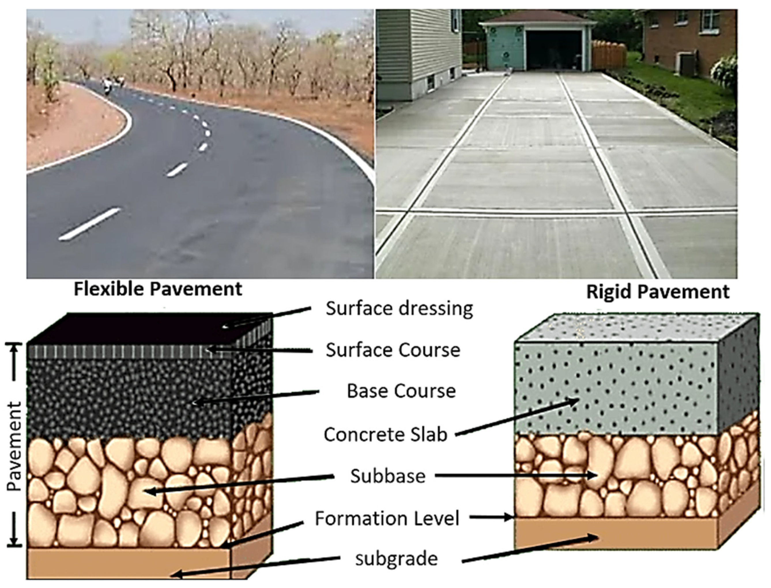
- Allaboutengineering, 2022. Available online: https://allabouteng.com/difference-between-flexible-pavement-and-rigid-pavement/ (accessed on 22 January 2022).
- Road Pavement Design Guide. 2000. Available online: https://www.kent.gov.uk/__data/assets/pdf_file/0012/13035/Making-it-Happen-Road-pavement-design-guide-July-2000.pdf (accessed on 26 February 2022).


| Cement/Lime Treated Subgrade | |
|
|
 | |
| In situ soil stabilisation process (Wirtgen-group.com (accessed on 7 May 2022)) | In situ soil treatment process in mixing chamber |
| Removal and Replacement | |
 |
|
| Removal and replace subgrade | |
| Subgrade Type | Mix Design | Treated | Soaked | Curing Days | CBR Values (%) |
|---|---|---|---|---|---|
| ASS 1 | (25%B + 75%K) | x | x | 0 | 8 |
| ASS 1 | (25%B + 75%K) | x | √ | 0 | 0.9 |
| ASS 2 | (35%B + 65%K) | x | x | 0 | 5 |
| ASS 2 | (35%B + 65%K) | x | √ | 0 | 0.8 |
| ASS 3 | (75%B + 25%K) | x | x | 0 | 9 |
| ASS 3 | (75%B + 25%K) | x | √ | 0 | 2 |
| ASS 1 | (8%L + 20%C) | √ | x | 7 | 80 |
| ASS 1 | (8%L + 20%C) | √ | x | 28 | 90 |
| ASS 1 | (8%L + 20%C) | √ | √ | 0 | 50 |
| ASS 2 | (8%L + 20%C) | √ | x | 7 | 60 |
| ASS 2 | (8%L + 20%C) | √ | x | 28 | 100 |
| ASS 2 | (8%L + 20%C) | √ | √ | 0 | 40 |
| ASS 3 | (8%L + 20%C) | √ | x | 7 | 30 |
| ASS 3 | (8%L + 20%C) | √ | x | 28 | 80 |
| ASS 3 | (8%L + 20%C) | √ | √ | 0 | 30 |
| HBM Category | A | B | C | D |
| Crushed rock coarse aggregate: (using aggregate with a coefficient of thermal expansion < 10 × 10−6 < per °C | - | CBGM B–C8/10 (or T3) SBM B1–C9/12 (or T3) FABM1–C9/12 (or T3) | CBGM B–C12/15 (or T4) SBM B1–C12/16 (or T4) FABM1–C12/16 (or T4) | CBGM B–C16/20 (or T5) SBM B1–C15/20 (or T5) FABM1–C15/20 (or T5) |
| Gravel coarse aggregate: (using aggregate with a coefficient of thermal expansion ≥ 10 × 10−6 per °C) | CBGM B–C8/10 (or T3) SBM B1–C9/12 (or T3) FABM1–C9/12 (or T3) | CBGM B–C12/15 (or T4) SBM B1–C12/16 (or T4) FABM1–C12/16 (or T4) | CBGM B–C16/20 (or T5) SBM B1–C15/20 (or T5) FABM1–C15/120(or T5) | - |
| Pavement layers | Materials Description | |||
| Surface course | Hot Rolled Asphalt (HRA) | |||
| Base course | Hydraulic Bound Mixture (HBM) | |||
| Subbase | Cement Bound Granular Mixture (CBGM) | |||
| (a) | |||||||||||||||||||||||
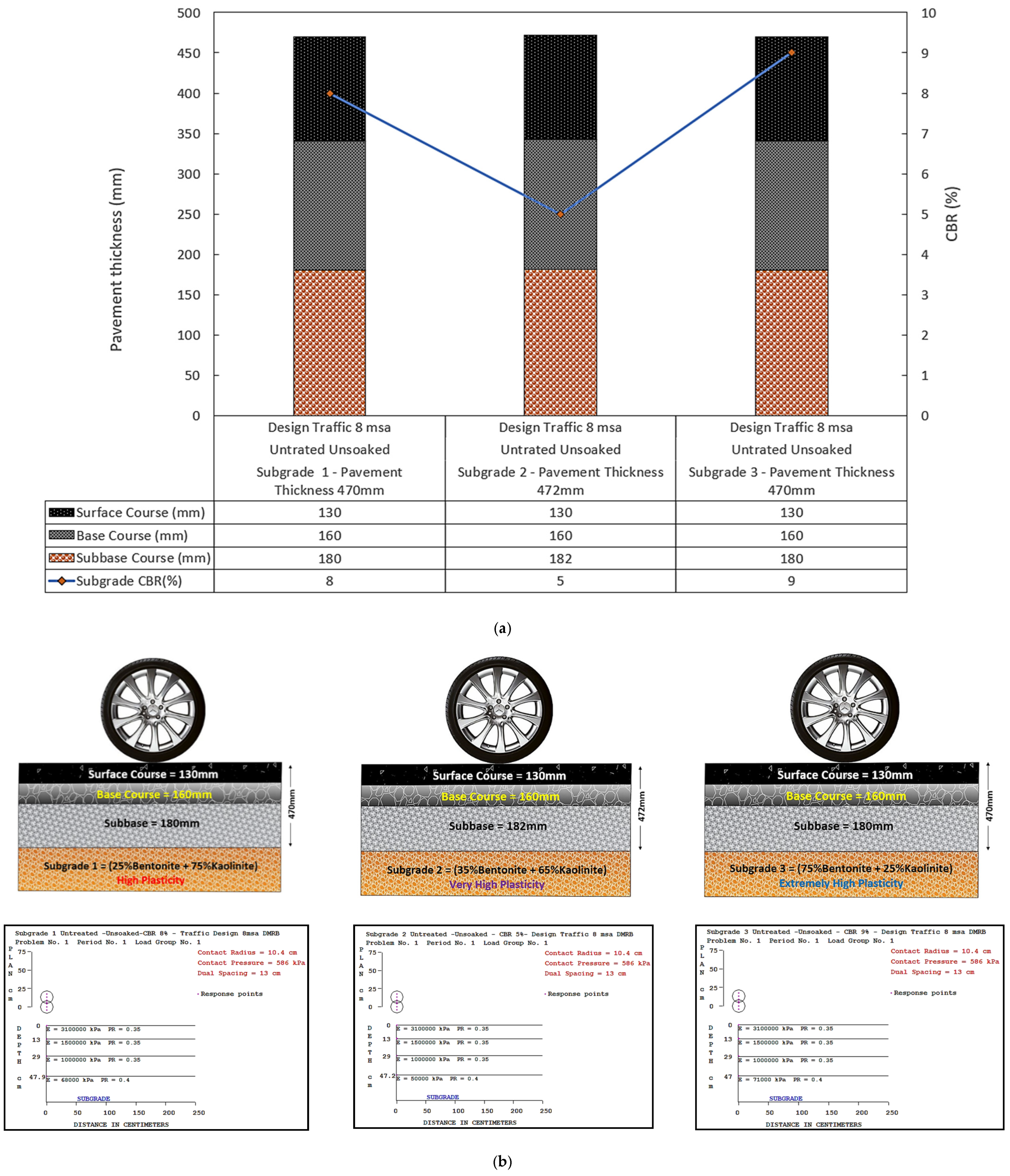
| ASS 1 (25% Bentonite + 75% Kaolinite) High Plasticity | ASS 2 (35% Bentonite + 65% Kaolinite) Very High Plasticity | ASS 3 (75% Bentonite + 25% Kaolinite) Extremely High Plasticity | |||||||||||||||||||||
| Flexible Pavement Layers | Material | Thickness (mm) | Treated | Curing (Days) | Soaked | CBR (%) | Design Traffic (msa) | Flexible Pavement Layers | Material | Thickness (mm) | Treated | Curing (Days) | Soaked | CBR (%) | Design Traffic (msa) | Flexible Pavement Layers | Material | Thickness (mm) | Treated | Curing (Days) | Soaked | CBR (%) | Design Traffic (msa) |
| Surface Course | HRA | 130 | Surface Course | HRA | 130 | Surface Course | HRA | 130 | |||||||||||||||
| Base Course | HBM | 160 | Base Course | HBM | 160 | Base Course | HBM | 160 | |||||||||||||||
| Subbase | CBGM | 180 | Subbase | CBGM | 180 | Subbase | CBGM | 180 | |||||||||||||||
| Subgrade | ASS | ∞ | √ | 7 | × | 80 | 8 | Subgrade | ASS | ∞ | √ | 7 | × | 60 | 8 | Subgrade | ASS | ∞ | √ | 7 | × | 30 | 8 |
| Total pavement thickness | 470 | Total pavement thickness | 470 | Total pavement thickness | 470 | ||||||||||||||||||
| (b) | |||||||||||||||||||||||
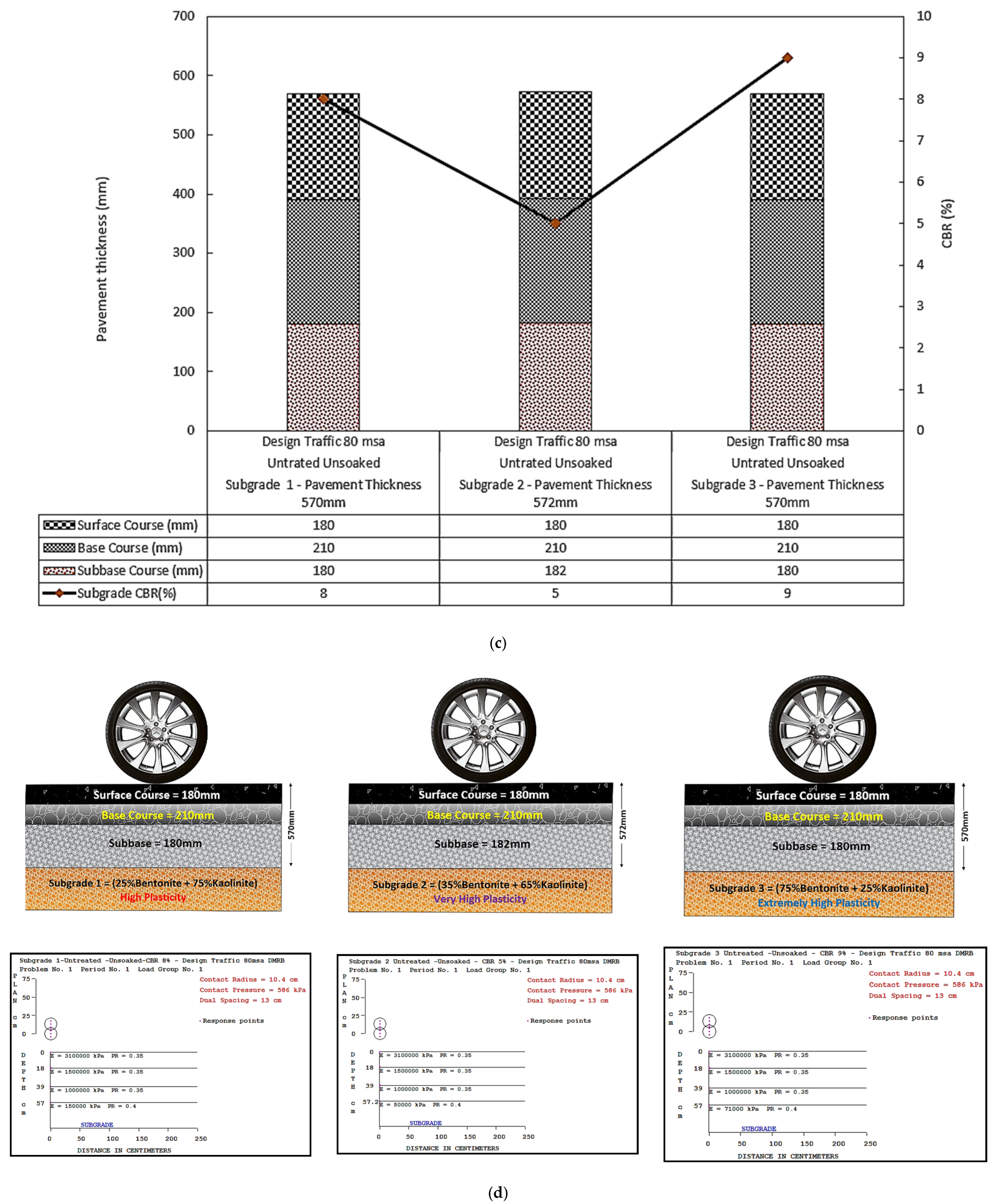
| ASS 1 (25% Bentonite + 75% Kaolinite) High Plasticity | ASS 2 (35% Bentonite + 65% Kaolinite) Very High Plasticity | ASS 3 (75% Bentonite + 25% Kaolinite) Extremely High Plasticity | |||||||||||||||||||||
| Flexible Pavement Layers | Material | Thickness (mm) | Treated | Curing (Days) | Soaked | CBR (%) | Design Traffic (msa) | Flexible Pavement Layers | Material | Thickness (mm) | Treated | Curing (Days) | Soaked | CBR (%) | Design Traffic (msa) | Flexible Pavement Layers | Material | Thickness (mm) | Treated | Curing (Days) | Soaked | CBR (%) | Design Traffic (msa) |
| Surface Course | HRA | 180 | Surface Course | HRA | 180 | Surface Course | HRA | 180 | |||||||||||||||
| Base Course | HBM | 210 | Base Course | HBM | 210 | Base Course | HBM | 210 | |||||||||||||||
| Subbase | CBGM | 180 | Subbase | CBGM | 180 | Subbase | CBGM | 180 | |||||||||||||||
| Subgrade | ASS | ∞ | √ | 7 | × | 80 | 80 | Subgrade | ASS | ∞ | √ | 7 | × | 60 | 80 | Subgrade | ASS | ∞ | √ | 7 | × | 30 | 80 |
| Total pavement thickness | 570 | Total pavement thickness | 570 | Total pavement thickness | 570 | ||||||||||||||||||
| (c) | |||||||||||||||||||||||
| ASS 1 (25% Bentonite + 75% Kaolinite) High Plasticity | ASS 2 (35% Bentonite + 65% Kaolinite) Very High Plasticity | ASS 3 (75% Bentonite + 25% Kaolinite) Extremely High Plasticity | |||||||||||||||||||||
| Flexible Pavement Layers | Material | Thickness (mm) | Treated | Curing (Days) | Soaked | CBR (%) | Design Traffic (msa) | Flexible Pavement Layers | Material | Thickness (mm) | Treated | Curing (Days) | Soaked | CBR (%) | Design Traffic (msa) | Flexible Pavement Layers | Material | Thickness (mm) | Treated | Curing (Days) | Soaked | CBR (%) | Design Traffic (msa) |
| Surface Course | HRA | 130 | Surface Course | HRA | 130 | Surface Course | HRA | 130 | |||||||||||||||
| Base Course | HBM | 160 | Base Course | HBM | 160 | Base Course | HBM | 160 | |||||||||||||||
| Subbase | CBGM | 180 | Subbase | CBGM | 180 | Subbase | CBGM | 180 | |||||||||||||||
| Subgrade | ASS | ∞ | √ | 28 | × | 90 | 8 | Subgrade | ASS | ∞ | √ | 28 | × | 100 | 8 | Subgrade | ASS | ∞ | √ | 28 | × | 80 | 8 |
| Total pavement thickness | 470 | Total pavement thickness | 470 | Total pavement thickness | 470 | ||||||||||||||||||
| (d) | |||||||||||||||||||||||
| ASS 1 (25% Bentonite + 75% Kaolinite) High Plasticity | ASS 2 (35% Bentonite + 65% Kaolinite) Very High Plasticity | ASS 3 (75% Bentonite + 25% Kaolinite) Extremely High Plasticity | |||||||||||||||||||||
| Flexible Pavement Layers | Material | Thickness (mm) | Treated | Curing (Days) | Soaked | CBR (%) | Design Traffic (msa) | Flexible Pavement Layers | Material | Thickness (mm) | Treated | Curing (Days) | Soaked | CBR (%) | Design Traffic (msa) | Flexible Pavement Layers | Material | Thickness (mm) | Treated | Curing (Days) | Soaked | CBR (%) | Design Traffic (msa) |
| Surface Course | HRA | 180 | Surface Course | HRA | 180 | Surface Course | HRA | 180 | |||||||||||||||
| Base Course | HBM | 210 | Base Course | HBM | 210 | Base Course | HBM | 210 | |||||||||||||||
| Subbase | CBGM | 180 | Subbase | CBGM | 180 | Subbase | CBGM | 180 | |||||||||||||||
| Subgrade | ASS | ∞ | √ | 28 | × | 90 | 80 | Subgrade | ASS | ∞ | √ | 28 | × | 100 | 80 | Subgrade | ASS | ∞ | √ | 28 | × | 80 | 80 |
| Total pavement thickness | 570 | Total pavement thickness | 570 | Total pavement thickness | 570 | ||||||||||||||||||
| (e) | |||||||||||||||||||||||
| ASS 1 (25% Bentonite + 75% Kaolinite) High Plasticity | ASS 2 (35% Bentonite + 65% Kaolinite) Very High Plasticity | ASS 3 (75% Bentonite + 25% Kaolinite) Extremely High Plasticity | |||||||||||||||||||||
| Flexible Pavement Layers | Material | Thickness (mm) | Treated | Curing (Days) | Soaked | CBR (%) | Design Traffic (msa) | Flexible Pavement Layers | Material | Thickness (mm) | Treated | Curing (Days) | Soaked | CBR (%) | Design Traffic (msa) | Flexible Pavement Layers | Material | Thickness (mm) | Treated | Curing (Days) | Soaked | CBR (%) | Design Traffic (msa) |
| Surface Course | HRA | 130 | Surface Course | HRA | 130 | Surface Course | HRA | 130 | |||||||||||||||
| Base Course | HBM | 160 | Base Course | HBM | 160 | Base Course | HBM | 160 | |||||||||||||||
| Subbase | CBGM | 180 | Subbase | CBGM | 180 | Subbase | CBGM | 180 | |||||||||||||||
| Subgrade | ASS | ∞ | √ | 3 | √ | 50 | 8 | Subgrade | ASS | ∞ | √ | 3 | √ | 40 | 8 | Subgrade | ASS | ∞ | √ | 3 | √ | 30 | 8 |
| Total pavement thickness | 470 | Total pavement thickness | 470 | Total pavement thickness | 470 | ||||||||||||||||||
| (f) | |||||||||||||||||||||||
| ASS 1 (25% Bentonite + 75% Kaolinite) High Plasticity | ASS 2 (35% Bentonite + 65% Kaolinite) Very High Plasticity | ASS 3 (75% Bentonite + 25% Kaolinite) Extremely High Plasticity | |||||||||||||||||||||
| Flexible Pavement Layers | Material | Thickness (mm) | Treated | Curing (Days) | Soaked | CBR (%) | Design Traffic (msa) | Flexible Pavement Layers | Material | Thickness (mm) | Treated | Curing (Days) | Soaked | CBR (%) | Design Traffic (msa) | Flexible Pavement Layers | Material | Thickness (mm) | Treated | Curing (Days) | Soaked | CBR (%) | Design Traffic (msa) |
| Surface Course | HRA | 180 | Surface Course | HRA | 180 | Surface Course | HRA | 180 | |||||||||||||||
| Base Course | HBM | 210 | Base Course | HBM | 210 | Base Course | HBM | 210 | |||||||||||||||
| Subbase | CBGM | 180 | Subbase | CBGM | 180 | Subbase | CBGM | 180 | |||||||||||||||
| Subgrade | ASS | ∞ | √ | 3 | √ | 50 | 80 | Subgrade | ASS | ∞ | √ | 3 | √ | 40 | 80 | Subgrade | ASS | ∞ | √ | 3 | √ | 30 | 80 |
| Total pavement thickness | 570 | Total pavement thickness | 570 | Total pavement thickness | 570 | ||||||||||||||||||
Publisher’s Note: MDPI stays neutral with regard to jurisdictional claims in published maps and institutional affiliations. |
© 2022 by the authors. Licensee MDPI, Basel, Switzerland. This article is an open access article distributed under the terms and conditions of the Creative Commons Attribution (CC BY) license (https://creativecommons.org/licenses/by/4.0/).
Share and Cite
Amakye, S.Y.O.; Abbey, S.J.; Booth, C.A. DMRB Flexible Road Pavement Design Using Re-Engineered Expansive Road Subgrade Materials with Varying Plasticity Index. Geotechnics 2022, 2, 395-411. https://0-doi-org.brum.beds.ac.uk/10.3390/geotechnics2020018
Amakye SYO, Abbey SJ, Booth CA. DMRB Flexible Road Pavement Design Using Re-Engineered Expansive Road Subgrade Materials with Varying Plasticity Index. Geotechnics. 2022; 2(2):395-411. https://0-doi-org.brum.beds.ac.uk/10.3390/geotechnics2020018
Chicago/Turabian StyleAmakye, Samuel Y. O., Samuel J. Abbey, and Colin A. Booth. 2022. "DMRB Flexible Road Pavement Design Using Re-Engineered Expansive Road Subgrade Materials with Varying Plasticity Index" Geotechnics 2, no. 2: 395-411. https://0-doi-org.brum.beds.ac.uk/10.3390/geotechnics2020018