
A Study of 5G Edge-Central Core Network Split Options


Fraunhofer FOKUS Institute, 10589 Berlin, Germany
*
Author to whom correspondence should be addressed.
Network 2021, 1(3), 354-368; https://0-doi-org.brum.beds.ac.uk/10.3390/network1030020
Submission received: 3 November 2021
/
Revised: 14 December 2021
/
Accepted: 17 December 2021
/
Published: 20 December 2021
(This article belongs to the Special Issue Emerging Networks and Systems for Edge Computing)
Abstract
:With the wide adoption of edge compute infrastructures, an opportunity has arisen to deploy part of the functionality at the edge of the network to enable a localized connectivity service. This development is also supported by the adoption of “on-premises” local 5G networks addressing the needs of different vertical industries and by new standardized infrastructure services such as Mobile Edge Computing (MEC). This article introduces a comprehensive set of deployment options for the 5G network and its network management, complementing MEC with the connectivity service and addressing different classes of use cases and applications. We have also practically implemented and tested the newly introduced options in the form of slices within a standard-based testbed. Our performed validation proved their feasibility and gave a realistic perspective on their impact. The qualitative assessment of the connectivity service gives a comprehensive overview on which solution would be viable to be deployed for each vertical market and for each large-scale operator situation, making a step forward towards automated distributed 5G deployments.
1. Introduction
To be able to meet the requirements of diverse applications coming from the vertical markets, 5G networks need to provide customized functionality and deployment options. For the three service classes defined, enhanced Mobile Broadband (eMBB), Ultra-Reliable and Low Latency Communications (URLLC) and massive Machine Type Communication (mMTC) [1], along with the new functionality, it became important where the network functions are placed in the network as it directly reflects in the connectivity service characteristics. For example, multimedia use cases based on eMBB can use edge network functionality for local content distribution and to relieve the backhaul of extensive communication. Similarly, mMTC applications, such as sensor based smart cities applications, can acquire and process information from many devices locally and transmit only reduced insight to central entities reducing the number of needed connections. The movement of the functionality to the edge provides a privacy-aware, low delay and higher reliability network, two main features in the focus of the URLLC vertical markets like enterprise networks, Industry 4.0 or Public Protection and Disaster Relief (PPDR) [2].
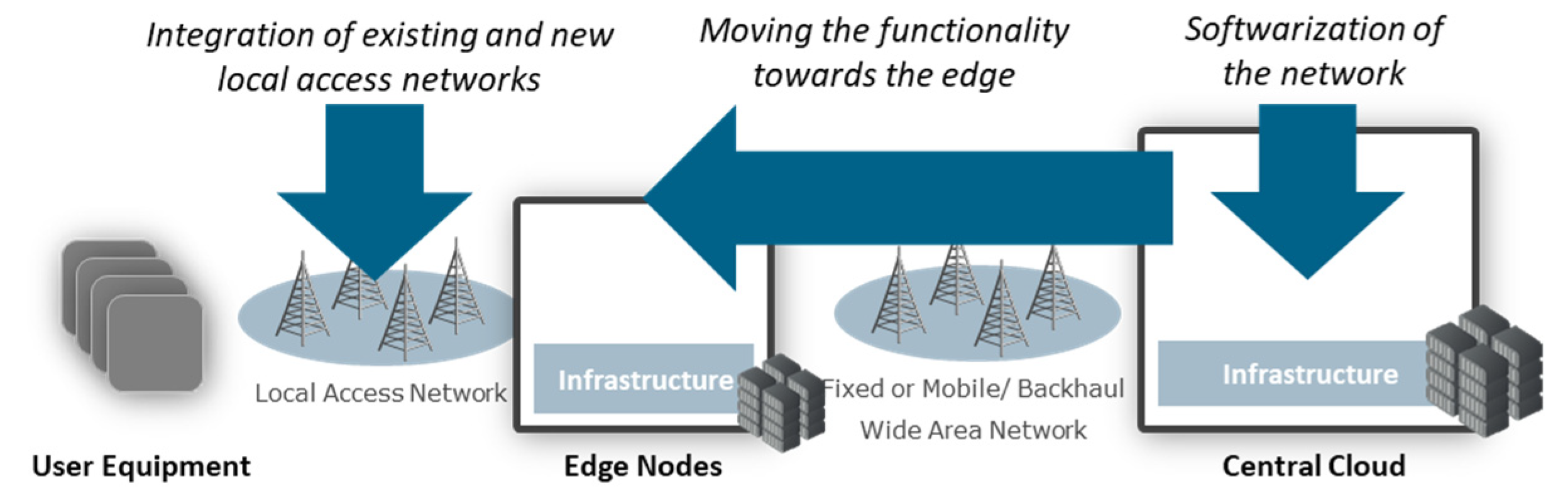
Services on the 4G network were able to offer a ubiquitous and uniform connectivity service to the devices by fully centralizing the core network functionality and binding it with the Radio Access Networks (RAN) through high capacity backhauls. After, 5G proposed a more distributed and localized approach. It presumes that part of the functionality can be moved towards the edge of the network and integrated with a local access network as illustrated in Figure 1. This direction is also enforced by the drastic decrease in infrastructure costs enabling affordable edge cloud deployments and by the softwarization of the network functions, enabling their deployment on any compute node available.
The 3GPP network standards factor the softwareization, providing an optimized Service-Based Architecture (SBA) [3,4] in which the network functions are communicate using highly adaptable and easy to develop interfaces using web service protocols. However, the standard leaves open how the 5G system should be deployed.
This article proposes a comprehensive set of 5G network deployment models and analyzes their benefits for a varied number of infrastructure and backhaul situations. Our main contribution is the analysis of different network function placement models and functional splits as blueprints to deploy the standard 3GPP 5G architecture.
With this, the 5G network architecture can be customized to meet the specific use case requirements while at the same time being aware of the implications of the underneath system. The opportunities brought by each deployment are practically evaluated through a comprehensive 5G testbed implementation, giving an indication on the opportunities of each deployment for the use cases.
Furthermore, a set of considerations followed by a practical evaluation is made on the end-to-end network management for such a distributed infrastructure being a significant feature for the further administration of the deployed 5G networks. The centralized and the distributed network management approaches are assessed as the two major options to handle such an infrastructure.
Through the practical evaluation, it is proven that many of the proposed functional split models are feasible for deployment, each with specific advantages for specific use cases. This provides a reliable basis for the further trials and customizations of the 5G networks in the direction of vertical markets deployments and further beyond-5G standardization.
The rest of this paper is structured as follows. Section 2 provides a concise overview of the 5G system and related work. Section 3 presents the different core split options and assesses their characteristics while Section 4 presents the equivalent for network management. Section 5 provides the testbed description and the evaluation results. Finally, in Section 6 we match the different models with the 5G use cases, outline further work and summarize our contributions.
2. Related Work
In this section, we concisely present the 5G architecture. To present such a complex system, a very large number of functional selections and simplifications are made. The architecture presented (Figure 2) is based on a combination of a minimal 3GPP Packet Core and a simplified network management and orchestration as this presents enough functional diversity.
The 5G system, as standardized by 3GPP ([3,4]), is composed of a User Equipment (UE) representing the mobile device, of a Radio Access Network (RAN), and of the Core Network (CN). The core network enables the connectivity of the subscribers with the following components. The Access and Mobility Function (AMF) includes the functionality for communication with both the UE and the RAN. It performs access and registration procedures, mobility management, and acts as a proxy for other management layers handled by other network functions. For authentication and authorization specific algorithms, the AMF uses the functionality provided by the Authentication User Service Function (AUSF). The Session Management Function (SMF) controls the User Plane Functions (UPF) to execute data path operations and set QoS parameters. Next to the subscriber state maintained in each network function, a centralized subscription profile is maintained in the Unified Data Management (UDM) for synchronization reasons. Much of the state information is replicated and, in many procedures, the UDM must be queried and updated to maintain this synchronization. For the end-to-end data plane, the UE is connected to the RAN over the radio interface and then from the RAN through one or more UPFs to the Data Network (DN).
In general, the UE is executing different procedures with the core network for authentication, authorization and access control including session establishment and mobility management resulting into end-to-end data paths through which the communication is executed.
As illustrated in Figure 2, potentially the core network functionality can be placed either at the edge or at the central infrastructure of the network. Due to resource consumption and synchronization reasons, only one network function should be used for each subscriber, be it at the edge or central. It is generally assumed that the edge infrastructure has significantly less compute resources and thus capacity to deploy applications than the central infrastructure. Additionally, the edge and the central infrastructure are interconnected via a backhaul network which could be based on optic fibers, wireless, satellite or a combination of them, resulting in different capacity and delay levels. The backhaul characteristics are translated directly into the control plane procedures as well as into the data plane delivery, thus mattering where the network functions are placed.
The 5G system has a standardized management system [5]. It is composed of many monitoring probes at different levels from infrastructure, software network components enabling a comprehensive understanding of the system’s performance including resources consumed, failures and reliability limitations, security breaches as well as related to the subscribers. The information from these probes is gathered in a monitoring server where it is further distributed to the network management elements in charge of interpreting the different data and making decisions on how to adapt the system. Based on the decision, the network management communicates with different Element Managers modifying the different network functions. Through its orchestration part, the network management also enables the deployment and the configuration of network functions and their introduction into the system. For these operations the same monitoring system and commands are used, however more oriented to the virtual infrastructure managers then to the network functions themselves.
A specific placement model was proposed by ETSI Mobile Edge Computing (MEC) standardization group [6]. It presumes that a single UPF is placed at the edge of the network to enable a localized data path. Albeit this model provides significant advantages for some of the use cases, other alternatives should be considered as we propose in the next section.
Another option to be considered is inter-operator roaming, where one visited operator offers the access and mobility services based on the home operator authorization and expected session management rules [7]. This can be applied for the edge-central split model considering that the edge network is a separate administrative domain with its own functioning policies.
3. Edge-Central Split Models
In this section, we present our edge-central split models for the 5G core network, and we make an initial assessment of the benefits provided by each of them for the different use cases. As illustrated in Figure 3, we developed three conceptual models of splitting the network each with multiple sub-options depending on the role transferred from the center to the edge of the network.
3.1. Local Offload Split Option
The local offload split option presumes that only one UPF, part of the data path, is present in the edge network, similarly to the architecture proposed by ETSI MEC. The rest of the control plane including decision elements and subscription profile are stored centrally. The UPF may handle only the locally offloaded data traffic or also forward the data traffic to the central side. For both options, a very large amount of the signaling in the control plane is passed over the backhaul, including the complete access and mobility management messages, the complete UE session management as well as the control messages from the SMF to the local offload UPF.
Such a split alternative is viable for network deployments where there is a reduced trust into the edge node as the full control plane is centralized such as edge nodes on premises of subscribers or third parties with no trust relationship. Furthermore, it could be potentially used for use cases where the delay and the capacity of the signaling does not impact the end-to-end services, although the backhaul could have a very large delay such as in-aircraft communication or live content acquisition using nomadic networks.
3.2. Locally Administrated Edge Split Option
The locally administrated edge network split option, presumes that the edge network includes the essential functionality necessary to adopt specific local policies in access control, mobility, and session management. For this, AMF and SMF are deployed locally next to the UPF from the previous option. The central network assists with authentication and authorization based on the subscription profile as well as with additional subscriber related policies from the PCF and with its own SMF for the sessions which have a data path passing through the central node too. The edge SMF may be responsible only for the local offload sessions or may be responsible also for the sessions which are forwarded to the central network. For both options, the amount of signaling between the edge and the central entities is highly reduced, being limited only to the authentication and authorization, respectively to the session management for sessions which pass also through the central node.
In this functional split, we propose to move the mobility and the session management to the edge of the network. In case a UE is moving out of the coverage range of the edge network, then a handover with AMF and SMF reselection must be executed. This procedure was already included in the 3GPP architecture for enabling distributed systems. It involves more network functions and procedure steps. Thus, it should be rarely used. This is possible by proper splitting of the subscribers, specifically by camping at the edge of the network the UEs which are rarely or never mobile. Furthermore, when two devices of separate edges need to communicate, then the session would involve two distinct AMFs and SMFs. However, for the single AMF and SMF case, two distinct sessions must be established, one for each of the UEs.
Such a split alternative is viable for deployments where a local set of policies must be enforced, while at the same time the subscribers are part of larger networks such as in the case of national roaming where the Non-Public Networks (NPNs) are bound to a larger network operator. It is also suitable for distributed enterprise networks with different edge deployments with their own administration and interconnected using own or third party backhauls with a centralized management, for example at the company’s headquarters. Furthermore, it could be potentially used as a roaming model for a large number of NPNs to provide interconnectivity between different entities such as the different parts of a production chain.
3.3. Autonomous Edge Split Option
The autonomous edge node deployment model presumes that the edge network is a complete network including all the specific network functions. It could potentially act as a local network, providing connectivity for the devices in the specific area without having the need of a backhaul. To communicate with outside entities, a data network may be deployed immediately from the backend of the autonomous edge. Through it, the data traffic can be forwarded as IP data traffic to the network. Furthermore, there are no options to support a seamless handover to a central network or to another edge as all the dynamic subscriber information is locally maintained.
However, the scope of such network is limited to the local area. It is not able to provide any sort of continuous mobility for the devices. To continue providing connectivity for same devices that are also in other autonomous edge networks, a new type of subscriber profile synchronization must be considered which is not in the scope of 3GPP standardization. The local user data repository is synchronized with a central one for the target devices using database synchronization mechanisms. This can be done at a prior moment to the deployment or during the deployment time.
Such a split alternative is most appropriate for deployments in which the local communication is most relevant, backhaul availability or capacity are highly limited and the trust in the edge infrastructure is highly increased. This is mostly true for PPDR use cases as well as for other nomadic deployments such as construction sites or logistics networks during public events.
4. Network Management Split Models
From the perspective of the network management, two different alternatives can be conceived: to have a part of the network management at the edge of the network, or to centralize the complete network management on the central entities. These options are illustrated in Figure 4 and presented underneath.
In the centralized network management option, all the operations related to the management of the system are implemented only at the central location. To acquire the required information from the edge as well as from the central part of the network a minimal monitoring server enabling the appropriate storage and pre-processing of monitored data is installed. Furthermore, to transmit commands to the edge and to the central part, different element managers are installed for the different components. When having a centralized network management and orchestration, all the monitored information as well as all the commands will have to be exchanged across the backhaul, occupying a specific level of the backhaul capacity and inducing a certain level of delay on executing the procedures [8].
Such a solution is highly attractive for edge nodes which are inter-connected with low delay and high capacity backhauls as the overhead of the management related communication is reduced while the system can respond to different events in a short time manner.
A second alternative would be to place a local network management on the edge of the network. In this situation, different decisions may be taken locally based on the local monitored information and enforced directly to the local element managers. It is to be noted that such a solution uses a significantly higher level of local compute and storage resources as it must locally process the specific data and make decisions.
Furthermore, an end-to-end orchestrator must be integrated into the system to coordinate the local network management decisions taken at the edge and at the central part of the network. It implies not only the introduction of a new network function able to coordinate the different elements, but also the development of new communication interfaces.
5. Testbed Implementation and Evaluation Results
In this section, we present the implementation in the form of a testbed of the proposed functional split models for the core network and for the network management. As the proposed alternatives are significantly complex in number of components to be deployed, we have implemented only a very limited set of these elements which provided significant results. Furthermore, although most of the implementation elements were executed on top of the same infrastructure, the tests were executed in isolation as not to have side effects from parallel running functionality.
For assessing the network characteristics of the three proposed deployment models, a testbed was developed including an edge and a central node on top of which three slices were deployed, i.e., parallel running software networks with its own configurations using the same hardware and virtualization infrastructure, as illustrated in Figure 5. As the measurements were targeted at the behavior of the system in uncongested situations, the exact performance of the infrastructure elements did not highly impact the overall measurements. As such, the edge and the central nodes were implemented using small capacity PCs.
The edge and the central network were connected using an Ethernet and a satellite backhaul. The Ethernet backhaul represents the potentially shortest and highest capacity path. The satellite network was implemented using a real Over-The-Air (OTA) capacity provided by the space communication company SES on a GEO satellite and ST Engineering satellite equipment [9,10]. The two networks were selected to represent the extreme cases for lowest and highest network delay to underline the effects of the communication between the edge and the central nodes. Other backhaul options such as the connectivity through a wireless or fixed network of a wide area network operator or directional wireless links can be seen as intermediary alternatives in terms of delay and capacity.
The testbed implementation was based on the Fraunhofer FOKUS Open5GCore [11], a reference 3GPP standard-based toolkit, addressing the R&D market and implementing the core network functionality and other network functions in a highly flexible way. Although the Open5GCore was integrated with a large number of commercially available base stations and UEs, for the presented measurements, we have used it with its own UE and gNB software emulations as it was simpler to monitor the status of the testbed and to maintain the RAN related side effects to a minimum. Instead, the link between the UE and the emulated gNB was implemented using an Ethernet connection. Furthermore, as we have used the same testbed setup for multiple demonstrations especially towards showcasing the advantages of the satellite network backhauling, a Data Network (DN) virtual machine with different domain specific applications. To simply change between the satellite and the ethernet backhaul, we added a Gateway (GW) virtual machine acting as a software access router for both the edge and the central infrastructure [12].
For the 5G core networks, the different procedures for the 5G registration, Packet Data Unit (PDU) session establishment and 5G deregistration were measured during functional tests. The measurements are presented for each of the deployment models together with the delay of communication between the SMF and UPF using the Packet Forwarding Control Protocol (PFCP). An additional control column was added including the median RTT across the backhaul as a control element.
For the evaluation of the end-to-end network management, a similar setup with the one used for the control plane split was used having an edge and a central node connected this time with Ethernet and with a simulated satellite link. The satellite link was simulated using the Linux Netem tool which we configured for a relevant delay of 580 ms, as measured for the core network split and with a limited network capacity of 2 Mbps in uplink and 26 Mbps in downlink. These values are consistent with the values measured over the real satellite link as used in the functional split testbed as described above. To have a faster testing process, we have chosen a second testbed with virtual links for this network’s management. Additionally, the normal variations of the backhaul network have a minimal impact on the measurements as the evaluated procedures have a significantly larger measurement scale, as presented in the evaluation section.
The two nodes were based on OpenStrack (Stein release) [13] enabling the dynamic deployment and the scaling of the different components. Virtual machines brought the necessary network dynamicity which was not included within the packet core testbed previously described. As a proof-of concept for the management operations, the deployment of the core network was considered. For the other operations related to fault, performance or security management, similar considerations can be made as most of the steps would be the same, as presented in the assessment below. For the deployment an ETSI Network Functions Virtualization (NFV) Management and Orchestration (MANO) orchestration function [14] was deployed based on the Fraunhofer FOKUS OpenBaton toolkit [15].
To showcase the distributed network management scenario, an additional End-to-End Orchestrator (ETEO) was implemented. As illustrated in Figure 6, for the ETEO a hierarchical approach was taken. It manages the multiple NFV MANO functions which manage different areas of the network, in our case the edge and the central network. From the network administration perspective, it is seen similar to an ETSI MANO exposing the same API for the management of the deployed system. The added value is the underneath API where it communicates commands to the NFV MANO orchestrators and coordinates their responses to provide a unitary system. It was assumed that the ETSI MANO components would not be aware of each other, to use already existing network management functions, without requiring any modifications, simplify the number of interfaces and at the same time to maintain the locality of their management operations.
A second setup was also deployed on top of the testbed described. It establishes a direct management of the edge infrastructure following the current ETSI MANO indications. In this setup, only the OpenBaton Orchestrator located at the central network is used which interacts with the two OpenStack installations as it is expected from the interaction between OpenStack and Virtual Infrastructure Managers (VIMs).
The measurements performed for the evaluation focus on the total deployment time of a Virtual Network Function (VNF). This is the time span from the moment the user starts the deployment process for a network service from a pre-downloaded VNF image up to the point at which the VNF is considered as deployed by the NFV orchestrator. In the distributed setup, the NFV orchestrator, which acts as the start and endpoint of the deployment, is the ETEO and in centralized setup it is Open Baton.
5.1. Local Offload Split Model Measurements
For the local offload split model, the Open5GCore components were split in three virtual machines: one on the edge including the UPF functionality and two on the central server, one including all the components in the control plane and the second one including a UPF for the data traffic connected to the data network.
The measurements were executed first over-the-air satellite network and secondly locally where the edge and the central node were co-located, using a local Ethernet backhaul. Each of the measurements were executed 25 times. A median delay of the different core network procedures is presented in Table 1.
The delay of the registration and of the PDU Establishment procedures was in the expected range, due to the specific delays of the satellite network. As these procedures are rather rare, being practically executed only when the device connects to the network for the first time, their effect is rather limited.
5.2. Locally Administrated Edge Network
For the locally administrated edge networks deployment model, two virtual machines were deployed at the edge, one including the AMF and SMF functionality and one with a UPF for local offloading. Another two virtual machines were deployed at the central location completing the core network, one with the AUSF and UDM functions and one with a second UPF for the centrally bound data traffic. Similarly, to the local offload split options, the measurements were first executed for the satellite backhaul followed by the local measurements with Ethernet backhaul. Each of the measurements were executed 25 times. The median delays of the procedures are presented in Table 2.
For the locally administrated edge networks, the 5G registration has a similar delay as in the local offload model. This is due to the large number of procedure steps which are executed between the AMF and the AUSF for the authentication and authorization of the UE and due to the lack of the other optional update procedures towards previous components which were not implemented in the Open5GCore. The 5G registration procedure had a slightly larger delay for Ethernet than in the case of the local offload as presented in Table 1. This is due to the split of the core network functions on top of two virtual machines instead of one. We will study this area further if such ultra-low delay of the control procedures would be required by the use cases.
As the AMF and the SMF were both located at the edge, the PFCP messages were exchanged only locally, with the local UPF having a 2 ms median. As such, the PDU session establishment was very fast regardless of the backhaul capabilities. It is assumed that a similar result would also be obtained for the other PDU session procedures including the modification, termination or establishment of other bearers. These measurements relate only to the local procedures. For the end-to-end ones where the central UPF is used, the delays should be like the local offload case, this time having the PFCP messages exchange on the other direction.
5.3. Autonomous Edge Network
For the autonomous edge network, the complete system was deployed in a single virtual machine with the network functions running as parallel programs, separated in Linux namespaces. In fact, because the synchronization of the user profiles in the UDM is executed asynchronous and using database specific synchronization tools, no connectivity with the central entities was required. This resulted in the complete communication to be localized at the edge, acting the same as a local campus network, covering only a limited concern area.
As noted in Table 3, such a solution has a minimal delay in all the control plane procedures, due to the much-reduced latency of the communication between the different network functions, practically virtual interfaces within the same virtual machine. In light of the very low delays obtained, it is to be further considered if for such small edge deployments, the current 5G architecture still is the most viable or if a more compact option consuming less resources and with less network management requirements should be used instead.
As all the core network components were co-located within the edge node, such a solution is very good for services which need a very low delay in the control plane as well as for the services which cannot rely on a continuous or resource-stable backhaul. However, it is to be noted that such a solution is not good for large size edge networks, as the grouping of functionality is missing the flexibility capabilities which a system with multiple network functions is offering.
5.4. Data Plane Considerations
For the three deployment models considered, there are also three data path implementations possible. First, a data path may be offloaded at the edge of the network enabling the UE to communicate through an edge UPF with the services which are deployed locally. Such an alternative is sustained by ETSI MEC as well as by other edge computing initiatives in order to reduce the end-to-end communication for critical applications, to maintain the privacy of the localized communication and to relieve the backhaul of part of the data traffic. Complimentary to this are end-to-end data paths which terminate at the central node. These are used for the communication where the centralization within the network operator is desired in order to maintain the privacy of the communication through the network provider or to support seamless handovers between edge nodes. A third alternative represents the termination of the data path also for centralized services at the edge of the network. In this case, the security and the handover capabilities are trade-off for a smaller overhead, as the data packets do not have to be encapsulated anymore.
As shown in Table 4, the delays of the different data paths are directly correlated to the delay of the backhaul with minimal, insignificant differences due to the encapsulation and decapsulation procedures. However, the measurements were executed only for large size packets close to the accepted Maximum Transmission Unit (MTU) for a continuous duration of less than 10 min. It is expected that the behavior would be different if much more smaller data packets are transmitted or could potentially vary for longer time duration experiments.
It is to be noted that the RTTs do not measure the complete data path. The RAN link was simulated and as such has a highly reduced delay than expected for such procedures. A realistic RTT value, considering the current available 3GPP Release 15 base stations, would range between 12 to 16 ms depending on the equipment used and on the communication environment.
5.5. End-to-End Network Management Considerations
For the network management testing, in the testbed illustrated in Figure 6 the deployment of the network service was performed 25 times to get a reasonable number of samples which can be used for calculating statistical properties. The measurement results are shown in Table 5 presenting the average and standard deviation of the total deployment time for both setups and both types of links.
As can be seen from the presented results, the VNF deployment time varies between the two types of network management. In the distributed one where we used the ETEO and OpenBaton orchestrators running near the locations of the managed service, the delay of the simulated satellite link is noticeable by a few seconds. However, looking at the total length of the deployment process, the difference due to the delay is not very significant.
In contrast, the results of the centralized management option, using one Open Baton orchestrator for managing both locations, show that the satellite link introduced a 60 s additional delay compared to the Ethernet procedure. This increase in deployment time is due to the high number of messages exchanged between the OpenBaton orchestrator and the OpenStack installed at the remote location. In the distributed setup, where the OpenBaton orchestrator resides at the same location as the VNFs, the impact of the satellite link is minimal. The only communication impacted by the delay is the one between OpenBaton and the ETEO and they do not require the same number of exchanges as there are between OpenBaton and the distributed setup. However, considering this, it is still surprising to see such an increase in deployment time, and there may be additional reasons why OpenBaton is affected this much by a high delay connection.
Looking at the difference of deployment time, it seems to be better to use the ETEO with OpenBaton deployed at the edge of the network instead of Open Baton alone managing the testbed over the satellite link. However, this only hold true if the satellite link is used. The Ethernet connection without the high delay, yields better results when using Open Baton as the only NFV orchestrator. The VNF deployments with the ETEO take about eight seconds longer. This can be explained with the overhead which is introduced by the ETEO which has to process the deployment itself, and most importantly, has to send requests to the Open Baton API for uploading the created VNF packages, NSDs and deployment requests.
From these results it can be concluded that in the presented scenario the ETEO can offer an advantage regarding deployment time when used with orchestrators at the network edge while only adding a few seconds of overhead compared to a standalone NFV orchestrator used over a fast connection. A similar set of results is expected to be true for other runtime management operations such as fault, configuration, performance, and security management. However, for these types of management, the local operations are even shorter than in cases of the deployment where multiple virtual machines must boot-up, the effect of the backhaul delay would be proportionally greater. It must be considered for each use case separately if this delay is significant enough to motivate the placement of additional functionality at the edge and thus, to consume some from the very limited number of resources available there.
6. Split Models Assessment
In this section, we give a targeted assessment of the core network and of the network management split models as evaluated in Section 5 towards their usability in the current beyond 5G vertical markets deployments. For this to be translated to use cases and to applications, a first intermediary step would be to compare the different solutions in terms of connectivity features they are offering and the trade-offs with the potentially available resources at the edge of the network and of the backhaul capacity.
In Table 6, the major functional elements from which the connectivity service provided by the core network are shortly summarized for the different deployment options.
The three core network split options are differentiated from each other from the way they treat the control and the data plane. For the control plane, the local offload requires all the procedures to be executed synchronously with the central node while the locally administrated edge requires only partially this and the autonomous edge none. Similarly, data paths can be local or end-to-end with the help of central entities. These differences bring variations in the connectivity functionality spanning from central handling in the local offload, partial local handling in the locally administrated edge and completely local in case of the autonomous edge. The variations impact the access control functionality including the authentication and authorization of the subscribers, the way the mobility management decisions are taken and the resource reservations and QoS for the different data sessions. Furthermore, they impact the privacy of the communication.
The inclusion of additional network functions at the edge of the network is dependent on the available compute resources. Previous benchmarks have shown that the 3GPP systems can be considered linearly scalable for a very large number of subscribers due to the almost complete independence of the subscriber procedures [16]. This implies that with more subscribers, more compute resources will have to be allocated to the network functions at the edge and obviously, with more network functions at the edge, even more compute resources are needed. As such, a proper dimensioning of the edge infrastructure should be performed.
The most important aspect when choosing one of these functional splits is the backhaul reliability dependency. It is expected that in situations with very reliable and high capacity backhauls, such as for most of the wide area network operators, a local offload solution is the best. However, in this case, an edge network is not needed, as the complete data traffic can be centralized with a minimal delay. For situations with less reliable backhauls such as best-effort Internet or with dedicated resources through a third-party operator, it would be better to use a locally administrated solution. This includes most of the Non-Public Network (NPN) deployments for example for factory shop floors in Industry 4.0 use cases, hospital networks, construction sites or logistics. The rest of NPNs where the backhaul availability cannot be guaranteed, it is better to use autonomous edge nodes no matter of the extra-resource consumption at the edge. This includes Public Protection and Disaster Relief (PPDR) use cases like ambulances, firefighters, technical support, or police as well as logistics and maritime networks, railway and in-aircraft communication.
Based on the quality of the backhaul, the appropriate network management solution should be chosen. Specifically, for nomadic or mobile use cases where high reliability is needed and autonomous edge nodes are deployed, a distributed solution is highly appropriate. For the other situations, the centralized split of the network management can be considered if the delay of the procedures and the potential loss of communication are considered. However, the distributed network management would be the best alternative in most of the cases as it can immediately and locally respond to the different requirements provided that a properly dimensioned solution is developed addressing such edge network deployments and not directly porting the wide area network operators’ ones.
Furthermore, with the more functionality added at the edge of the network, the network management operations needed to be executed is increased. Each of the edge nodes includes more network functions which must be installed, configured, and upgraded. Additionally, the complexity of the runtime network management is also significantly increased in terms of fault management, performance, optimization management and security management. This increase in complexity should be traded off against the end-to-end communication delay requirements quantified in this article.
7. Conclusions and Further Activities
In the previous sections, we have presented a set of functional split options of the core network. As demonstrated, they provide highly distinct services in terms of operations’ delay and manageability, making the choice of the appropriate option essential for the efficient deployment of the specific use cases. With the provided evaluation, this article underlines the potential to optimally address the different use cases. This potential must be proven towards different realistic deployment environments and further customized towards the use cases. We are currently engaged in such a refinement operation with some verticals including Industry 4.0, multimedia acquisition, and PPDR networks. It is expected that an additional set of communication requirements will be gathered from these activities would need a new stage of assessment of the proposed solutions.
Furthermore, the network management solution presented here needs to be further refined in the direction of system runtime management where the different operations are highly time-constrained. For this, a new solution of optimized communication across the backhaul is need for monitoring for element management as well as for bulk transmissions of administrative policies.
With the advent of 6G networks, it is foreseen that these initial beyond-5G core and network management options will become even more fluid, enabling a high level of dynamic functionality placement as well as a more morphing core network [17]. As the core network connectivity service characteristics as reflected in Table 6 remain the same, it is expected that also the split models will follow the same generic principles. Regardless, they will still have to be adapted to the fore coming 6G architecture as well as to the expected increase in the infrastructure capacity at the edge and the even more heterogeneous backhaul variation.
Author Contributions
Conceptualization, M.C. and T.M.; methodology, M.C. and P.C.; validation, M.C. and P.C.; formal analysis, P.C.; investigation, M.C.; writing—original draft preparation, M.C. and P.C.; writing—review and editing, M.C. and T.M.; visualization, M.C.; supervision, T.M. All authors have read and agreed to the published version of the manuscript.
Funding
This work was partially funded by ESA ARTES AT project “SATis5” (Demonstrator for Satellite Terrestrial Integration in the 5G Context)—ESA/ESTEC Contract No.: 4000120663/17/NL/CLP and by EC H2020 5G-PPP ICT-17 5G-VINNI project.
Data Availability Statement
Data can be provided by authors upon request. Data can be verified using a Fraunhofer FOKUS Open5GCore testbed.
Acknowledgments
The authors would like to thank Maria Guta from ESA/ESTEC for her valuable technical support in the SATis5 project. Furthermore, the authors would like to thank Konstantinos Liolis (SES), Joe Cahill (iDirect), and our colleagues Eric Troudt, Björn Riemer and Thomas Briedigkeit for their support in the testbed development and assessment.
Conflicts of Interest
The views expressed herein can in no way be taken to reflect the official opinion of the European Space Agency or of the European Commission.
References
- Popovski, P.; Trillingsgaard, K.F.; Simeone, O.; Durisi, G. 5G Wireless Network Slicing for eMBB, URLLC, and mMTC: A Communication-Theoretic View. IEEE Access 2018, 6, 55765–55779. [Google Scholar] [CrossRef]
- Li, Z.; Uusitalo, M.A.; Shariatmadari, H.; Singh, B. 5G URLLC: Design challenges and system concepts. In Proceedings of the 2018 15th International Symposium on Wireless Communication Systems (ISWCS), Lisbon, Portugal, 28–31 August 2018; pp. 1–6. [Google Scholar]
- 3GPP TS 23.501. System Architecture for the 5G System (5GS), v17.0.0. Available online: www.3gpp.org (accessed on 30 March 2021).
- 3GPP TS 23.502. Procedures for the 5G System (5GS), v17.0.0. Available online: www.3gpp.org (accessed on 31 March 2021).
- 3GPP TS 28.533. Management and Orchestration; Architecture Framework, v17.0.0.0. Available online: www.3gpp.org (accessed on 23 September 2021).
- Kekki, S.; Featherstone, W.; Fang, Y.; Kuure, P.; Li, A.; Ranjan, A.; Purkayastha, D.; Jiangping, F.; Frydman, D.; Verin, G.; et al. MEC in 5G Networks; ETSI White Paper, 28; ETSI: Sophia Antipolis, France, 2018; pp. 1–28. ISBN 979-10-92620-22-1. [Google Scholar]
- Corici, M.; Chakraborty, P.; Magedanz, T.; Gomes, A.; Cordeiro, L.; Mahmood, K. 5G Non-Public-Networks (NPN) Roaming Architecture. In Proceedings of the 12th International Conference on Network of the Future, Coimbra, Portugal, 6–8 October 2021. [Google Scholar]
- Corici, M.; Magedanz, T. One Layer to Rule Them All: Data Layer-oriented 6G Networks. In Shaping Future 6G Networks: Needs, Impacts and Technologies; Wiley: New York, NY, USA, 2021. [Google Scholar]
- Liolis, K.; Cahill, J.; Higgins, E.; Corici, M.; Troudt, E.; Sutton, P. Over-the-air demonstration of satellite integration with 5G core network and multi-access edge computing use case. In Proceedings of the 2019 IEEE 2nd 5G World Forum (5GWF), Dresden, Germany, 30 September–2 October 2019; pp. 1–5. [Google Scholar]
- Corici, M.; Liolis, K.; Burkhardt, F.; Gheorghe-Pop, I.; Covaci, S.; Politis, C.; Geurtz, A.; Koernicke, J.; Völk, F.; Kapovits, A. SATis5: A 5G Testbed Integrating Satellite and Terrestrial Infrastructures. In Proceedings of the Advanced Satellite Multimedia Systems Conference (ASMS), Berlin, Germany, 10–12 September 2018. [Google Scholar]
- Corici, M.; Emmelmann, M.; Hauswirth, M.; Magedanz, T. Paving the Way for Local and Industrial 5G Networks and testbeds. ERCIM News, 12 April 2019; p. 7. Available online: https://ercim-news.ercim.eu/en117/special/paving-the-way-for-local-and-industrial-5g-networks-and-testbeds (accessed on 3 November 2021).
- Krentz, K.F.; Corici, M.I. Poster: Multipath Extensions for WireGuard. In Proceedings of the 2021 IFIP Networking Conference (IFIP Networking), Espoo and Helsinki, Finland, 21–24 June 2021; pp. 1–3. [Google Scholar]
- OpenStack Software. Available online: https://www.openstack.org/ (accessed on 3 November 2021).
- ETSI. GS NFV 002 Network Functions Virtualisation (NFV). Architectural Framework, V1.2.1. 2014. Available online: https://www.etsi.org/deliver/etsi_gs/nfv/001_099/002/01.02.01_60/gs_nfv002v010201p.pdf (accessed on 3 November 2021).
- OpenBaton Toolkit. Available online: https://openbaton.github.io/ (accessed on 3 November 2021).
- Corici, M.; Gheorghe-Pop, I.; Cau, E.; Corici, A.A.; Magedanz, T. A benchmarking methodology for virtualized packet core implementations. In Proceedings of the 2016 IEEE Conference on Standards for Communications and Networking (CSCN), Berlin, Germany, 31 October–2 November 2016; pp. 1–6. [Google Scholar]
- Corici, M.; Troudt, E.; Chakraborty, P. An Ultra-Flexible Software Architecture Concept for 6G Core Networks. In Proceedings of the 2021 IEEE 4th 5G World Forum (5GWF), Montreal, QC, Canada, 13–15 October 2021; pp. 1–5. [Google Scholar]
Figure 1.
Major Trends in 5G Networks.

Figure 2.
Simplified 5G Architecture. The core network functions are depicted twice at edge and at central to illustrate that they can be placed at either location.
Figure 2.
Simplified 5G Architecture. The core network functions are depicted twice at edge and at central to illustrate that they can be placed at either location.

Figure 3.
The 5G core network split options.

Figure 4.
Network management and orchestration split options.

Figure 5.
Testbed implementation.

Figure 6.
Network management testbed implementation.


Table 1.
Median delay of local offload 5G core network functionality split control plane procedures.
Table 1.
Median delay of local offload 5G core network functionality split control plane procedures.
| Procedure | 5G Registration | PDU Session Establishment | PFCP Messages | 5G Deregister | Control: Backhaul RTT |
|---|---|---|---|---|---|
| With satellite backhaul (ms) | 1369 | 1415 | 630 | 1320 | 582 |
| With Ethernet backhaul/locally measured (ms) | 16.7 | 42.8 | 2.6 | 14 | 2 |
Table 2.
Median delay of locally administrated edge network deployment option control plane procedures.
Table 2.
Median delay of locally administrated edge network deployment option control plane procedures.
| Procedure | 5G Registration | PDU Session Establishment | PFCP Messages | 5G Deregister | Control: Backhaul RTT |
|---|---|---|---|---|---|
| With satellite backhaul (ms) | 1380 | 40 | 2 | 1342 | 581 |
| With Ethernet backhaul/locally measured (ms) | 20.7 | 38.8 | 2 | 14.2 | 2 |
Table 3.
Median delay of the autonomous edge node deployment option.
| Procedure | 5G Registration | PDU Session Establishment | PFCP Messages | 5G Deregister | Control: Backhaul RTT |
|---|---|---|---|---|---|
| With satellite backhaul (ms) | 20.70 | 9.34 | 1.22 | 14.90 | N/A |
Table 4.
Average data path delays.
| Data Path | RTT Delay | Control: Backhaul RTT |
|---|---|---|
| Edge offloading | 2 | N/A |
| Central with edge offloading | 585 | 582 |
| Central—satellite backhaul | 584 | 582 |
| Central—Ethernet backhaul | 4 | 2.6 |
Table 5.
Average data path delays.
| Setup | Backhaul Type | Duration (s) | Deviation (s) |
|---|---|---|---|
| Distributed Management | Satellite | 106.051 | 4.24 |
| Ethernet | 102.823 | 3.562 | |
| Centralized Management | Satellite | 161.287 | 4.039 |
| Ethernet | 94.879 | 3.256 |
Table 6.
Core network split models assessment.
| Feature | Local Offload | Locally Administrated Edge | Autonomous Edge |
|---|---|---|---|
| Control Plane | Centralized | Half-distributed | Distributed |
| Data Plane | Split | Split | Local only |
| Access Control | Centralized | Assisted by central | Local |
| Mobility | Full network transparent | Coherent changes in network zones | Only local support |
| QoS | Centrally defined | Mixed between local and central | Local |
| Privacy at the edge | Local data paths | Local control and data paths | All communication |
| Backhaul reliability dependency | Large | Partial | Limited |
| Number of interactions | Same as in a 5G system with multiple UPFs | ||
| Number of components to be managed (with available edge compute resources) | +UPFs at each edge | +AMF, SMF and UPF at each edge | +complete core at each edge |
| Suitable network management | Centralized | Distributed | Distributed |
Publisher’s Note: MDPI stays neutral with regard to jurisdictional claims in published maps and institutional affiliations. |
© 2021 by the authors. Licensee MDPI, Basel, Switzerland. This article is an open access article distributed under the terms and conditions of the Creative Commons Attribution (CC BY) license (https://creativecommons.org/licenses/by/4.0/).
Share and Cite
MDPI and ACS Style
Corici, M.; Chakraborty, P.; Magedanz, T. A Study of 5G Edge-Central Core Network Split Options. Network 2021, 1, 354-368. https://0-doi-org.brum.beds.ac.uk/10.3390/network1030020
AMA Style
Corici M, Chakraborty P, Magedanz T. A Study of 5G Edge-Central Core Network Split Options. Network. 2021; 1(3):354-368. https://0-doi-org.brum.beds.ac.uk/10.3390/network1030020
Chicago/Turabian StyleCorici, Marius, Pousali Chakraborty, and Thomas Magedanz. 2021. "A Study of 5G Edge-Central Core Network Split Options" Network 1, no. 3: 354-368. https://0-doi-org.brum.beds.ac.uk/10.3390/network1030020