Article

Low-Voltage Ride through Capability Augmentation of DFIG-Based Wind Farms Using Series-Parallel Resonance-Type Fault Current Limiter

1
Department of Electrical & Electronic Engineering, Rajshahi University of Engineering & Technology, Rajshahi 6204, Bangladesh
2
School of Electrical, Computer and Telecommunications Engineering, University of Wollongong, Wollongong, NSW 2522, Australia
*
Author to whom correspondence should be addressed.
Submission received: 17 September 2021 / Revised: 20 October 2021 / Accepted: 27 October 2021 / Published: 1 November 2021

Abstract

:
The introduction of doubly fed induction generators (DFIGs) has facilitated the utilization of wind energy to a great extent and constituted distributed generation (DG) systems in remote places. Therefore, long transmission lines are required to interconnect with the utility grid and, consequently, different short-circuit faults interrupt this transmission. Use of different fault current limiters (FCLs) minimizes the effect of faults and allows normal operation with minimum interruption in power flow. In this study, a series-parallel resonance-type fault current limiter (SPRFCL) is presented for enhancing the low-voltage ride-through (LVRT) capability of DFIG-based wind farms. The SPRFCL preserves the nominal voltage and power quality within the permissible limit during normal operation and during disturbances irrespective of the type of fault. The effectiveness of the proposed SPRFCL is validated by simulating both symmetrical and asymmetrical faults. Alongside the SPRFCL, two state-of-the-art FCLs—the parallel resonance-type fault current limiter (PRFCL) and the capacitive bridge-type fault current limiter (CBFCL)—are considered to investigate and compare the relative performances. Several graphical and numerical studies assure the efficacy of the proposed SPRFCL in wind farm application in multiple aspect. Moreover, the stunning total harmonic distortion (THD) values with the proposed technique signifies the excellency over its competitors. Additionally, the sub-synchronous resonance (SSR) analysis confirms the supremacy of SPRFCL for series compensated lines.

1. Introduction

Fossil energies like natural gas, coal and oil are the main sources of vast power generation in today’s world. However, the reserves of these fuels are declining rapidly with the pace of time. Besides, they are responsible for producing bulk amount of CO 2 that pollutes the environment gradually [1]. By contrast, renewable energy sources (RESs) offer some distinctive advantages over fossil energy, for instance, low-cost, sufficiency, cleanliness, etc. [2]. Wind energy solely contributes to the largest part of this green energy, as it possesses improved efficiency than rest of the RESs [3]. Moreover, the wind power generation system has become more efficient than ever with the addition of doubly fed induction generator (DFIG) [4]. Some remarkable features that make the DFIG stand out are its reduced cost, compact size, energy efficiency, voltage controllability, as well as active and reactive power regulation system. Most importantly, while rotational speed of wind turbine changes, the stator voltage and frequency can be made constant by regulating the frequency of rotor winding [5]. To utilize the electrical power in every corner of the world, widespread transmission systems are built. As a result, climatic disorder and miscellaneous problems occur short circuit in the power system very often. As the stators of the DFIG are coupled to the utility grid directly, any disturbance in grid eventually affects the wind turbine performance. Therefore, to ensure stable operation of DFIG based wind farms (WFs), low-voltage ride through (LVRT) capability improvement is needed.
In order to enhance the LVRT capability, different approaches incorporating software and hardware-based solutions have been proposed in different literature [6,7,8,9]. Some noticeable software approaches that are introduced by the modification of rotor side converter (RSC) control system are virtual damping flux-based control, robust control, inductance emulating control, scaled current tracking control, etc. [7,8,9]. These solutions are feasible for systems with lower voltage sag, but fail to satisfy the LVRT requirements when the voltage sag is severe. Hardware-based solutions solve the problems with software solutions and fulfill the LVRT requirements for both small and large voltage sags [10,11,12]. Therefore, hardware-based solutions are crucial to enhance the LVRT capability for modern power systems.
From the early stage, researchers have documented numerous hardware approaches like crowbars [13], DC choppers [14], energy storage system (ESS) [15], static synchronous series compensator (SSSC) [16], static dynamic resistors (SDR) [17], static synchronous compensator (STATCOM) [18], unified inter-phase power controllers (UIPC) [19], fault current limiters (FCLs), and so on. The applications of crowbars are a fairly old LVRT scheme that installs resistance between the rotor and RSC [13]. Although the crowbars can improve the rotor current response to some extent, they have the problem that they absorb reactive power from the grid during faults [20]. DC choppers are another popular LVRT scheme that can improve the DC link voltage response in a fair margin [14]. However, controlling the switching of DC choppers is complicated and also their performances are somewhat inferior to the crowbars. Then a combining strategy including both the crowbars and DC choppers is proposed in [21] and later, a comparative study is carried out in [20]. The SSSC, SDR, STATCOM, UIPC, and ESS provide an effective series interface to fulfill the requirement of LVRT. However, their applications in DFIG are not feasible in most of the cases, as they become bulky in higher rated wind farms and increase the overall installation and maintenance cost. Furthermore, they comprise costly power converters that add to the overall cost. Therefore, FCLs are the most appropriate solution to improve the LVRT capability of DFIG-based wind farms regarding the application feasibility and cost [17,22,23,24].
The FCLs must be capable of showing zero impedance during normal operation, and they must switch to an impedance during fault so that the fault current can be reduced [22]. Amendment of transient stability, power quality, and reliability are some other key features of FCLs. Among different FCLs, one of the most commonly used ones are superconducting fault current limiters (SFCLs) [25,26,27]. Based on their structure, they are broadly categorized into quench type and non-quench type SFCLs. Quench type SFCLs are of various types such as resistive, inductive, magnetic shielding, etc. [28,29], and non-quench types include the bridge, saturated core, as well as active types [30]. Although the SFCLs consume no power during normal operation, their implementation is complicated due to the requirement of superconducting material and a cryogenic cooling system. Additionally, their usage is limited, owing to high implementation and maintenance cost in DFIG-based WF.
Solid-state fault current limiters (SSFCLs) are another popular type of FCL that consist of semiconductor devices like insulated gate bipolar transistor (IGBT), gate turn off (GTO), integrated gate-commutated thyristor (IGCT), silicon controlled rectifier (SCR), and so on [31]. These SSFCLs are free from mechanical contact and electric arc, and so it has a long life span and reduced noise output. In [32], application of bridge-type FCL is introduced to improve the power quality and transient stability. They are proved to be better than the SDBRs that was proposed a few years earlier [33]. BFCLs with multiple topology have been proposed over the years, namely, inductive BFCL [34] and resistive BFCL [35], to augment the LVRT capability. However, they were unable to maintain the reactive power flow after the fault, which is required for fast voltage stability in DFIG system. To resolve this problem, a capacitive BFCL (CBFCL) was proposed in [10,36], which is more efficient in transient stability enhancement. Moreover, it provides the required reactive power support after fault clearance. However, there are still some scope of improvement as the CBFCL generates high transient spike over-voltage during fault, and high rated diodes are required for normal operation.
In recent years, several resonance-type FCLs incorporating switching elements have been documented and used in DFIG-based WF to limit the excess fault current. Series resonance FCL (SRFCL) is one of the resonant-type FCLs that can aid the LVRT requirements of DFIG-based WFs [37]. The SRFCL is simple in construction and requires no additional switching scheme like traditional FCLs. However, the SRFCL is subjected to substantial voltage dip during fault that can have adverse affect to the rest of the healthy system [38]. In [39], a parallel resonance scheme along with conventional BFCL has been proposed to improve LVRT performance, which is then further explored to improve the LVRT performance of DFIG-based WFs [5,12,40]. Under normal operation, the bridge circuit of the BFCL carries the line current and switches to the parallel resonant circuit during fault to provide high impedance path to minimize the fault current [5,12,40]. The bridge circuit comprises four power diodes, switching elements, and a DC reactor. Therefore, a significant power loss at normal state is unavoidable, and it further causes voltage sag or swelling during fault transients. As a consequence, normal operation of wind turbine is affected and reactive power support during faults also weakens [24].
The series-parallel resonance-type FCL (SPRFCL) [41] is a new technique which is applied in this paper to enhance the LVRT capability of DFIG based WFs. To the best of our knowledge, this SPRFCL has never been applied in a DFIG-based system to improve its transient performance. This SPRFCL uses the technique of series resonance as well as parallel resonance incorporating switching devices. During normal operation, series resonance is employed, and in fault condition parallel resonance is activated to limit the fault current by controlling the solid-state switching devices. To check the efficacy of this SPRFCL, its performance is compared with well-established CBFCL [10,36] and PRFCL [5,12,40]. MATLAB/Simulink platform is used to model those FCLs and the system for analyzing their performances.
The remainder of the paper is structured as follows. Section 2 describes the configuration of the proposed SPRFCL. Section 3 provides a brief description about existing FCLs that we are comparing the SPRFCL with. The proposed system configuration is discussed in Section 4. Performances of the FCLs are evaluated in Section 5, and Section 6 concludes the paper.

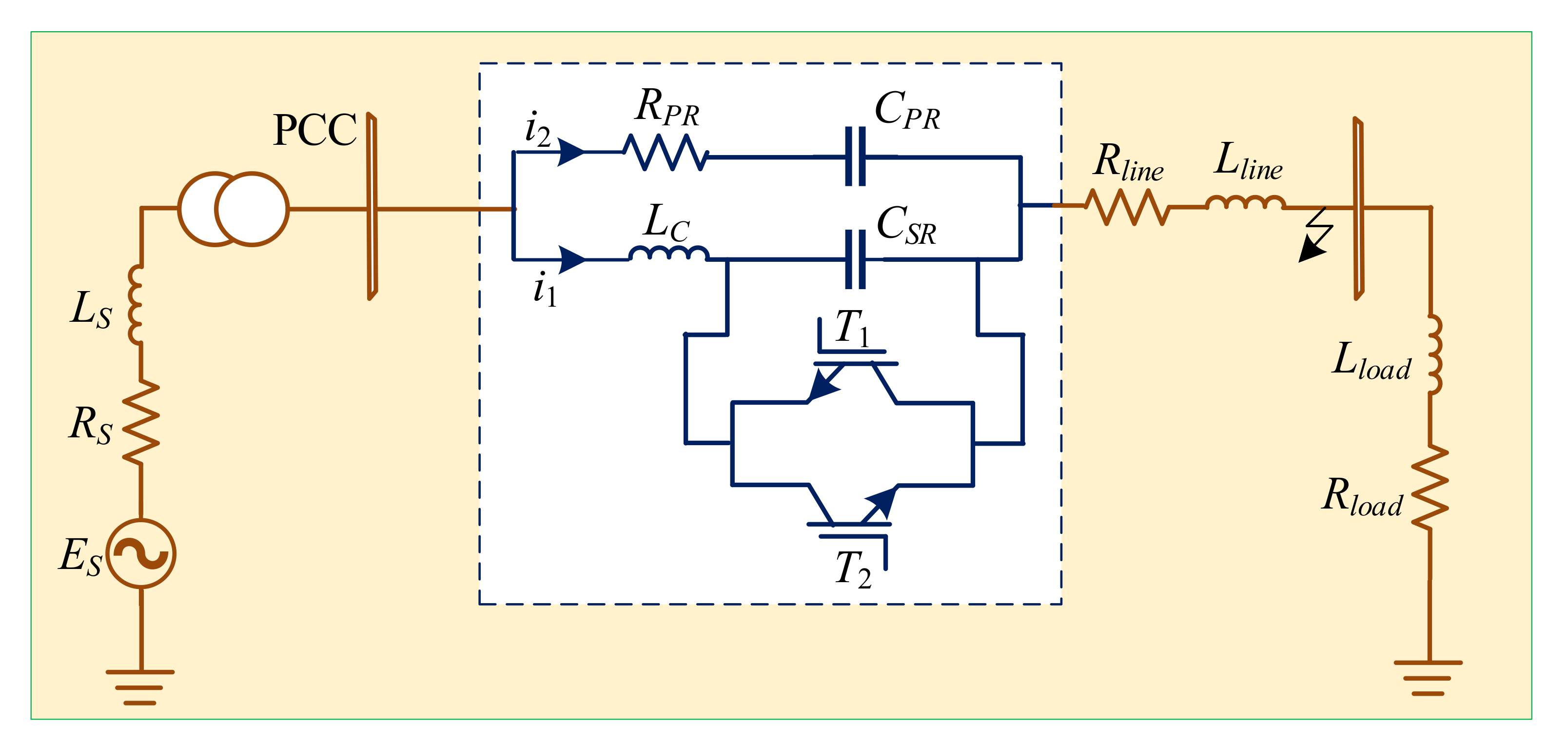
2. Series-Parallel Resonance-Type Fault Current Limiter (SPRFCL)
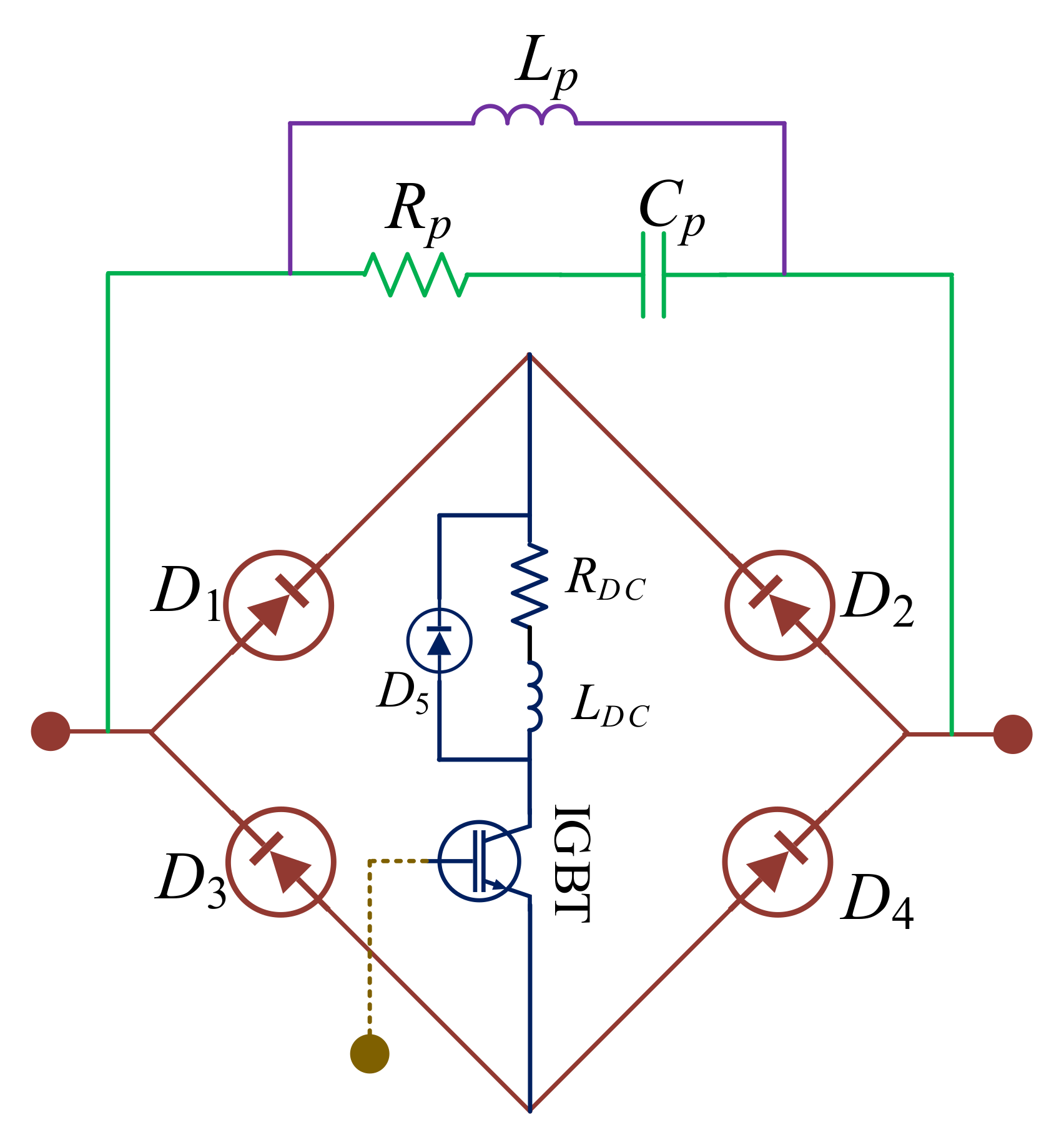
2.1. Architecture

The proposed SPRFCL architecture is depicted in Figure 1, where a couple of parallel branches are used to form a series-parallel resonance circuit [41]. The upper branch comprises the capacitor C P R and the resistor R P R , while the lower branch includes the capacitor C S R , inductor L C , and two IGBTs as an anti-parallel semiconductor switch.
In normal operation, both the T 1 and T 2 IGBT switches are turned off, and therefore series resonance takes place at power frequency keeping the L C and C S R in series with the transmission line. Theoretically, this series resonance condition offers zero impedance along the line, keeping the voltage at the point of common coupling (PCC) unaffected. During the normal period, almost all the line current passes along the L C and C S R except some leakage current across the high impedance path containing C P R and R P R . Therefore, normal period current is hardly hampered by the proposed SPRFCL as it maintains a smooth flow of current without affecting the LVRT performance.
Meanwhile, during a fault, both the T 1 and T 2 IGBT switches are turned on, and thus the C S R is short-circuited. The elements of the upper branch consisting of C P R and R P R , and the elements of lower branch consisting of L C , form parallel resonance. Thus, the high impedance path formed as the result of parallel resonance and the resistor R P R suppress the surge of fault current simultaneously. The resistor effectively improves the transient stability during fault condition and helps in fast recovery of voltage and line current [41].

2.2. Mathematical Model

The mathematical model of the SPRFCL is dependent on whether it is in series resonance or parallel resonance condition. To understand the differences between the two modes, the theoretical analysis is segmented into two states.
Normal state: During normal operation, L C and C S R carry the line current. Therefore, the equivalent resistance can be defined as R T = R S + R l i n e + R l o a d , and the equivalent inductance is thus L T = L S + L l i n e + L l o a d . Here, R S , R l i n e , and R l o a d are associated to source, transmission line, and load resistances, respectively. L S , L l i n e , and L l o a d refer to the inductances of the source, transmission line, and load, respectively. Applying Kirchhoff’s voltage law (KVL) in the circuit that is depicted in Figure 1, we get the following differential equation [41]:
R T i L ( t ) + L T d i L ( t ) d t + L C d i 1 ( t ) d t + 1 C S R i 1 ( t ) d t = V m s i n ( ω t )
solving (1), we get
i L ( t ) = A e R T L T + L C ( t t 0 ) + B ( t )
where B and A are defined as
B ( t ) = V m sin ( ω t δ T ) Z T
A = I L ( t 0 ) V m s i n ( ω t 0 δ T ) Z T
where Z T = R T 2 + ω 2 L T 2 and δ T = tan 1 ( ω ( L T + L C ) / R T ) . I L ( t 0 ) refers to the line current at t = t 0 .
Fault state: Let a short-circuit fault occur at time t = t 1 near the load bus, as shown in Figure 1. The magnitude of the fault current without any FCL can be expressed as
i L ( t ) = I L ( t 0 ) V m s i n ( ω t 0 δ F ) R F 2 + ω 2 L F 2 e R F L F ( t t 0 ) + V m s i n ( ω t δ F ) R F 2 + ω 2 L F 2
where δ F , R F and L F can be defined as
δ F = tan 1 ( ω L F / R F )
R F = R S + R l i n e + R n
L F = L S + L l i n e ,
and R n is the fraction of the resistance during fault.
Now, when a fault occurs whilst the SPRFCL is connected to the system, the parallel resonance employs to suppress the high current. The mathematics behind this fault suppression can be expressed as
i L ( t ) = A 1 e s 1 t + A 2 e s 2 t + I L , m s i n ( ω t + φ )
where s 1 , 2 = α ± α 2 + ω d 2
α = 1 2 R F L F + L C + 1 R P R C P R
ω d 2 = R F R F + R P R 1 ( L F + L C ) C P R
The expression of I L , m that is used to calculate the forced response, can be expressed as
I L , m φ = V m Z F Z a Z a + Z b
where Z F = R F + j ω L F + Z a / Z b
Z a = R P R j / ω C P R
Z b = j ω L C
Any fault near the load bus is responsible for fluctuations in PCC voltage waveform. In addition to that, sag or swell in PCC voltage occurs during fault, and a large fault current flows. To address the aforementioned difficulties, many analysis has been performed to find out suitable combination of capacitor as well as inductor of SPRFCL. Therefore, appropriate values are considered to cause both series and parallel resonance at power system frequency considering nominal PCC voltage and lowest fault current. Moreover, in order to get fast recovery after fault and to damp the fluctuations effectively, considerable value of resistor is chosen. Considering all the criterion and obeying the design procedure discussed in [41], the values of the parameters of the SPRFCL that are used throughout the analysis for C S R , L C , C P R , and R P R are 78.18 μ F, 90 mH, 78.18 μ F, and 18 Ω , respectively.

2.3. Working Principle and Control Strategy

Operation of the SPRFCL depends on the voltage available at the PCC. The SPRFCL is designed to offer approximately zero impedance at series resonance and high impedance at parallel resonance. Therefore, the PCC voltage is continuously monitored to determine whether it is higher or lower than the threshold voltage level. Literature suggests that, instead of tracking the three phase voltage at the PCC directly, converting the three phase quantity into direct (d-axis) and quadrature (q-axis) counterparts yields better tracking results and precise detection of faults [12,26]. In the conversion process, the three-phase PCC voltage is first converted into d & q-axis quantities, denoted as V d , ϕ and V q , ϕ in Figure 2. The V d , ϕ and V q , ϕ are then individually squared and added together. The square root of the sum is denoted as V d q , ϕ , it is the quantity that is used to compare with a threshold level ( V t h ) of 0.9 pu to detect faults. Depending on the measured voltage level, the operating mode of the SPRFCL is decided.
As long as the PCC voltage stays above the threshold level, i.e., when there is no fault, the normal operation of the SPRFCL is executed. In this state, control signal or gate pulse of two anti-parallel IGBT switches is determined to make sure the circuit is in series resonance condition. Therefore, the control signal turns off the T 1 and T 2 switches and the C S R constitutes series resonance with L C . During this period, a negligible amount of current passes through the upper parallel branch owing to its high impedance.
Whenever the PCC voltage goes below the threshold voltage due to any short circuit fault, the fault state mode of the SPRFCL is activated. Therefore, the switches T 1 and T 2 are turned on by providing appropriate control signal, and the C S R is thus short circuited. As a result, parallel resonance is formed, which provides high impedance path to subside the fault current properly.

3. Comparison with Existing FCLs

The efficacy of the SPRFCL in DFIG-based WF system is compared with some well-known high performance existing FCLs, i.e., capacitive bridge-type FCL (CBFCL) [10,36] and parallel resonance-type FCL (PRFCL) [5,12,40]. Short description of these FCLs are discussed in the following subsections.

3.1. Capacitive Bridge-Type Fault Current Limiter (CBFCL)

The topology of the CBFCL is outlined in Figure 3. The CBFCL is placed at the exact same position as the proposed SPRFCL. It possesses a couple of elementary parts: the bridge circuit and the shunt path [10,36]. The diode bridge is generally made up of four power diodes ( D 1 D 4 ) , a DC reactor, and a semiconductor switch. A free-wheeling diode ( D 5 ) and an internal resistance are connected across the DC reactor to protect it. The DC reactor smooths the ripple current as it charges up to the rated line current in the same direction for both negative and positive half cycle. However, high impedance is offered by shunt path that contains a capacitor C s h in series with a resistor R s h . During normal operation, the IGBT switch is kept on, and the line current passes through the diodes and DC reactor, which have negligible effect on normal PCC voltage. In the fault condition, the IGBT switch is turned off and the line current is forced to flow through the shunt path. The shunt path is designed in such a way that it can provide a high-impedance path that is able to suppress the fault current and improves the transient performance of the overall system. Considering this and following the design procedure discussed in [10,36], the values of C s h and R s h are chosen as 50 μ F and 18 Ω , respectively. Furthermore, the value of the DC reactor is taken as 10   m H , which is enough for the system. The IGBT gate control of the CBFCL is also same as Figure 2 to get the fair comparison with SPRFCL.

3.2. Parallel Resonance-Type Fault Current Limiter (PRFCL)

Simple schematic diagram of the PRFCL is demonstrated in Figure 4. Its topology is somewhat similar to that of the CBFCL as it has the same diode bridge and a shunt path. The difference is that the shunt path of the PRFCL consists of a parallel configuration of a series RC branch and an inductor [5,12,40]. This unique combination of the shunt path form parallel resonance and used to suppress the high current in fault condition. During normal operation, entire line current is carried out by the bridge circuit except a little amount of leakage current through the shunt path. During fault, the IGBT in bridge circuit turns off and routes the current over the parallel branch. The IGBT gate control logic can be found at Figure 2. The parameters’ value of shunt path are selected so as to conform parallel resonance at power frequency. As parallel resonance offers high impedance at resonant frequency, this property is used to suppress the fault current smoothly whenever fault occurs. The values of L p , C p , and R p are chosen as 78.18 m H , 90 μ F, and 18 Ω , respectively. For a fair comparison with the proposed SPRFCL, those values of the PRFCL to offer resonance at power frequency are chosen the same as the SPRFCL’s parallel resonance part during fault.

4. Study System Configuration

The system modeled in Figure 5 has been exploited to study the performance of the SPRFCL. It comprises an aggregated 20 MW WF with ten DFIGs, each of them rated at 2 MW. The individual ratings of each DFIG is enlisted in the Appendix A. The WF gets connected to the utility grid through a step-up transformer and a double circuit transmission line, one of which holds the SPRFCL. The grid is represented by an equivalent voltage source incorporating infinitesimal internal impedance. To spare the analysis about excessive transients for the negative sequence components due to the phase jump of the supply voltage during unbalanced voltage sag during fault, we considered the grid connection to be strong as the issues relating to the phase voltage jump do not occur with strong connection between the wind farm and the grid [42]. The PCC acts as the medium between the single- and double-circuit lines. The control signal from the PCC ensures whether the system is in fault or normal condition, and actuates the SPRFCL to perform its operation corresponding to the signal. The DC link capacitor joins the rotor-side converter (RSC) together with the grid side converter (GSC). The RSC involves an IGBT-based six-pulse two-level full-bridge power converter as well as a control device. The active and reactive power of the DFIG are mainly controlled by RSC, specifically by controlling the pulse width of the converter switches. On the other hand, GSC regulates the DC link voltage by controlling the gate pulse of the IGBT-based six-pulse two-level power converter. The control parameters of the RSC and GSC control circuits are modeled by the discussion carried out in [33]. Symmetrical as well as asymmetrical faults are applied in the transmission line to investigate the LVRT capability of the SPRFCL. The entire system is modeled and the outcomes are analyzed in the MATLAB/Simulink platform. Different system parameters are listed in Table A1 in the Appendix A.

4.1. Modeling of the Wind Turbine

The wind turbine (WT) converts the kinetic energy of the wind into mechanical energy. The mechanical power ( P m ) harnessed from wind power can be expressed as [23,43]
P m = 1 2 ρ A ω C p V ω 3
where ρ is the air density, V ω is the wind speed, A ω = Π R 2 is the area of the rotor blade with radius R, and C p is the coefficient of power. C p is a function of the tip speed ratio λ and the blade pitch angle β , which can be written as
C p ( λ , β ) = 0.22 ( 116 λ c 0.4 β 5 ) e 12.5 λ c
where
λ c = 1 1 λ + 0.08 β 0.035 β 3 1

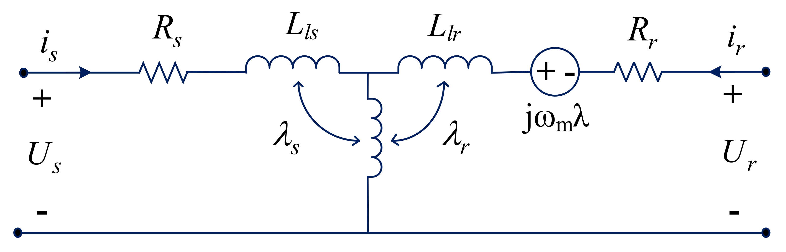
4.2. Modeling of the DFIG

The equivalent model of the DFIG can be derived following Park’s model, as shown in the equivalent circuit of Figure 6 [44]. The fifth-order two-axis representation of Park’s transformation model is used to model the DFIG [45]. A d q reference frame that is rotating synchronously, is used with its d-axis aligned with the stator flux. The rotor excitation current and the electrical torque comprise a decoupled control and therefore, the reference frame rotates at the same speed as the stator flux. As per the synchronous reference frame of this model, the stator and rotor voltages and the fluxes are expressed as [22,23]
u s = R s i s + d d t λ s
u r = R r i r + d d t λ r j ω m λ r
λ s = L s i s + L m i r
λ r = L r i r + L m i s
where u s and u r denote the space vector of the stator and rotor voltages, respectively; i s and i r denote the space vector of the stator and rotor currents, respectively; the stator resistances are denoted by R s and R r ; L m is the magnetizing inductance; λ s and λ r are the space vector of the stator and rotor fluxes, respectively; and ω m denotes the slip angular frequency. Neglecting the stator and rotor resistances and combining (11) and (12), we get
L m L s u s = σ d i r d t j σ L r ( ω s ω r ) i r + j ω r L m L s λ s
where
σ = 1 L m 2 L s L r
During the normal operation, d i r d t = 0 and u s is almost equal to j ω r λ s . Therefore, (15) can be rewritten as
L m L s u s = j σ L r ( ω s ω r ) i r + u r
After a fault occurs in the system, the magnetic flux and the inductor current are continuous at the fault instant. Therefore, the values of stator flux and rotor current remains unchanged. Thus, the change in stator voltage during fault can be derived from (Equation (17)) as
L m L s Δ u s = σ d i r d t + Δ u r
As the voltage capacity of the RSC ( Δ u r ) is limited, there will be a surge of high fault current if the voltage dip is severe (i.e., Δ u s ).

5. Performance Evaluation of the Proposed SPRFCL

This section extensively demonstrates and interprets the simulation results of proposed SPRFCL in DFIG-based WF. Both symmetrical three-line-to-ground (3LG) and asymmetrical double line to ground (2LG) faults are simulated in the transmission line section of the model system to compare the relative performances of the FCLs in improving the LVRT capability. The faults are initiated at t = 2.1 s and withdrawn at t = 2.2 s. The wind speed is considered constant at 15 ms 1 , as the time span of fault is too short for the variable wind speed to cause any effect on transient performance. In order to investigate the relative performance among proposed and other mentioned FCLs, following cases are considered for both symmetrical and asymmetrical faults:
Case 1: System with no FCL
Case 2: System with the CBFCL
Case 3: System with the PRFCL
Case 4: System with the proposed SPRFCL
Findings for both graphical and computational analyses are discussed in the subsequent subsections.

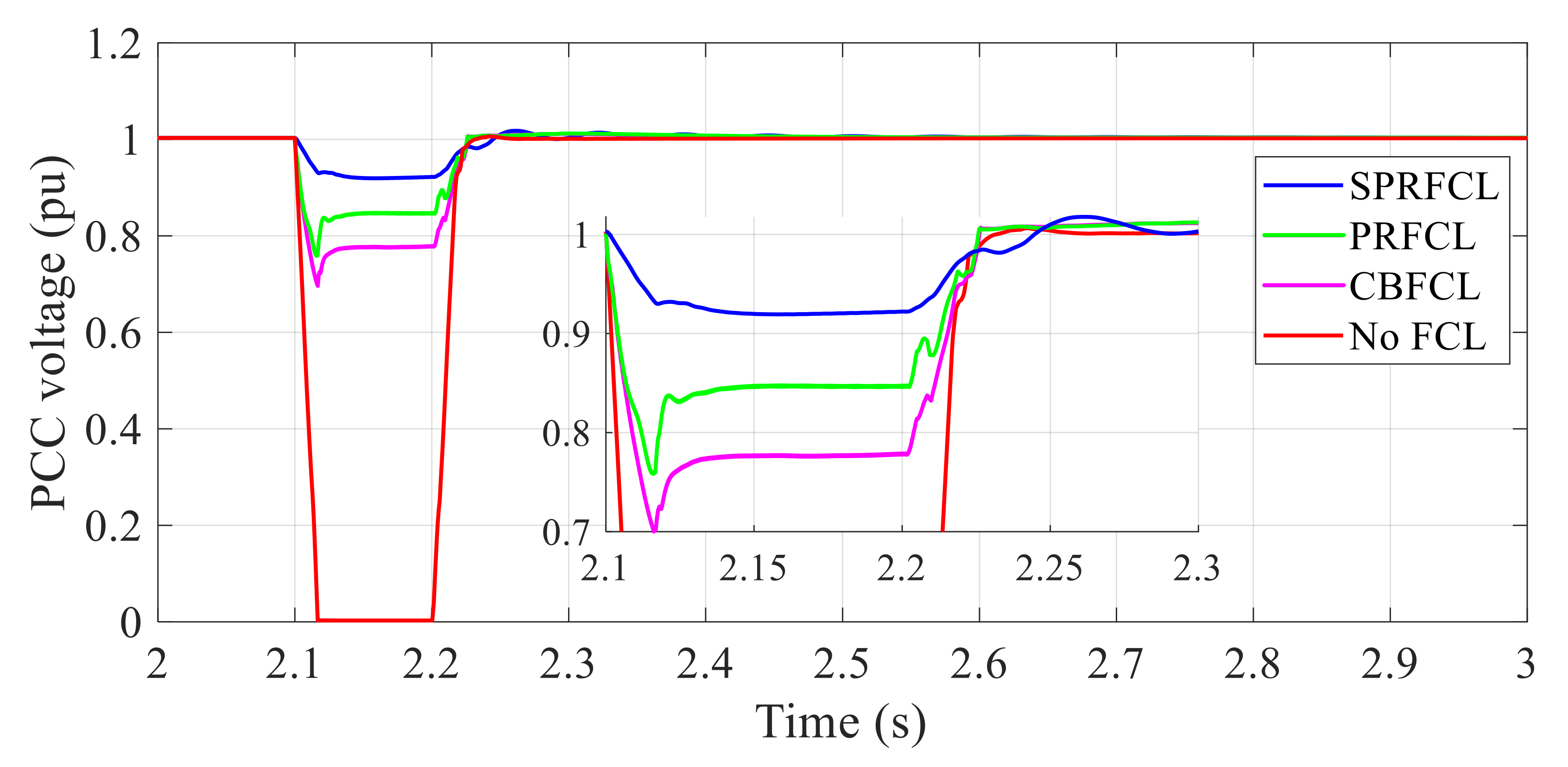
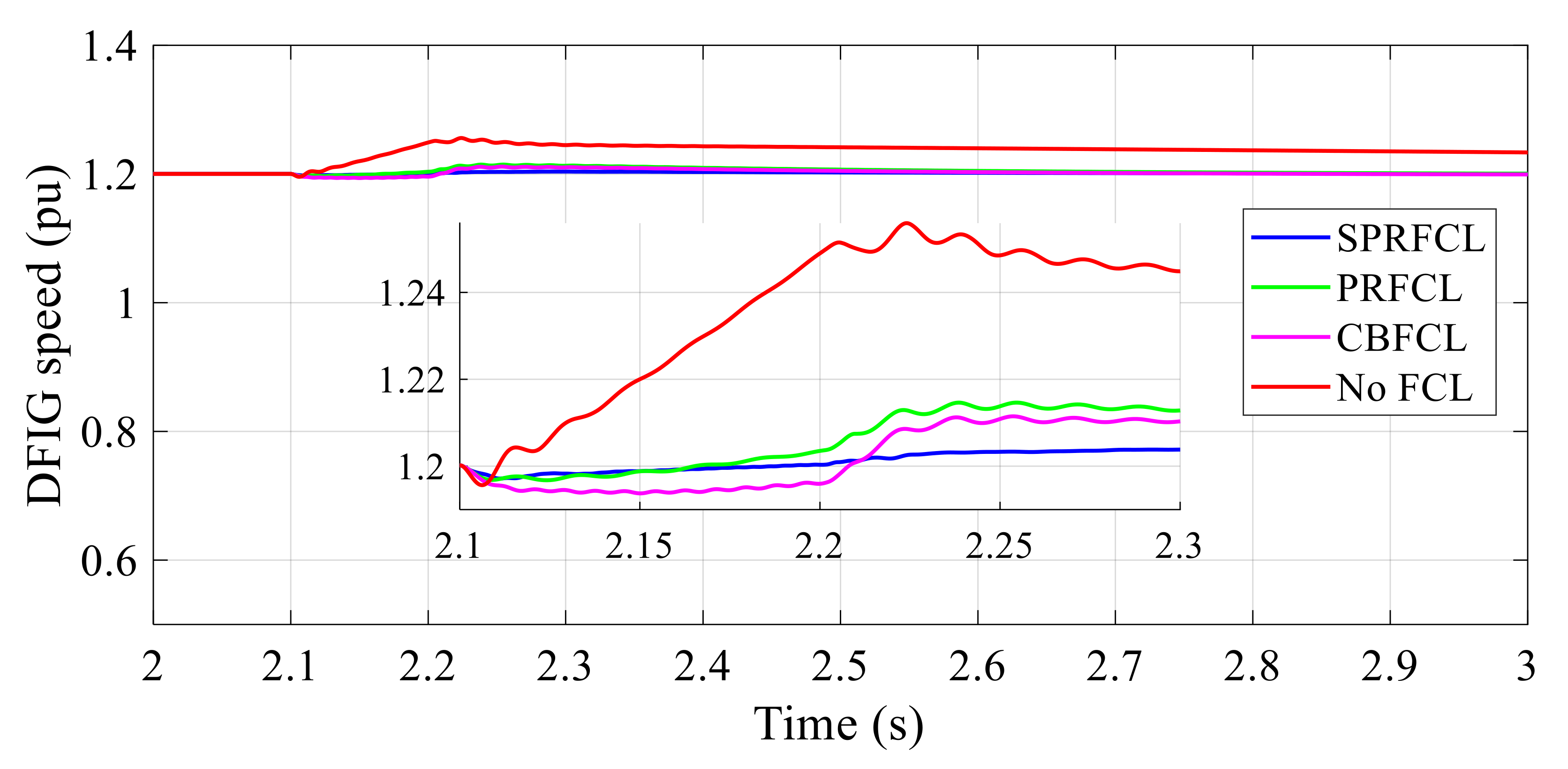
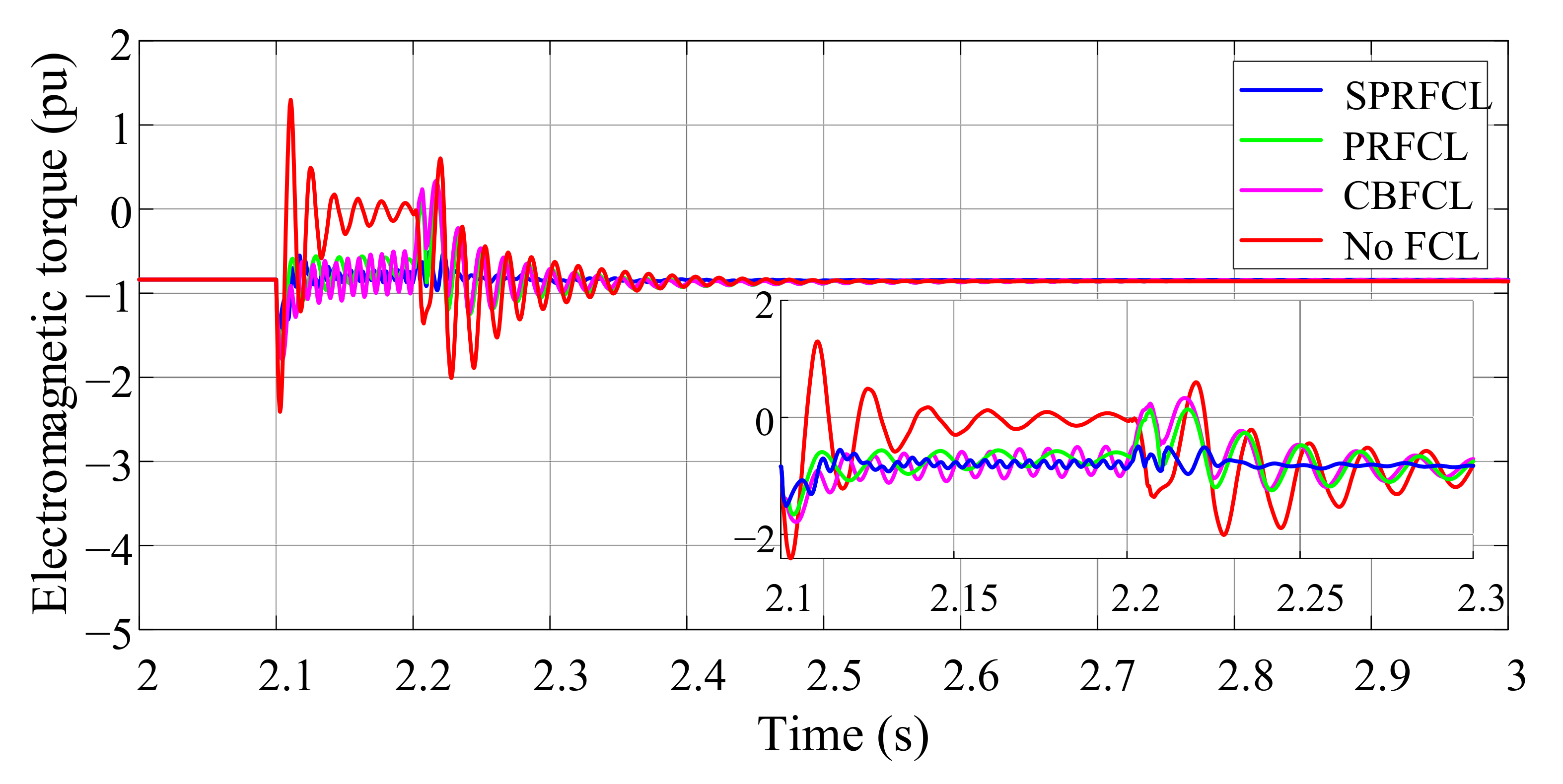
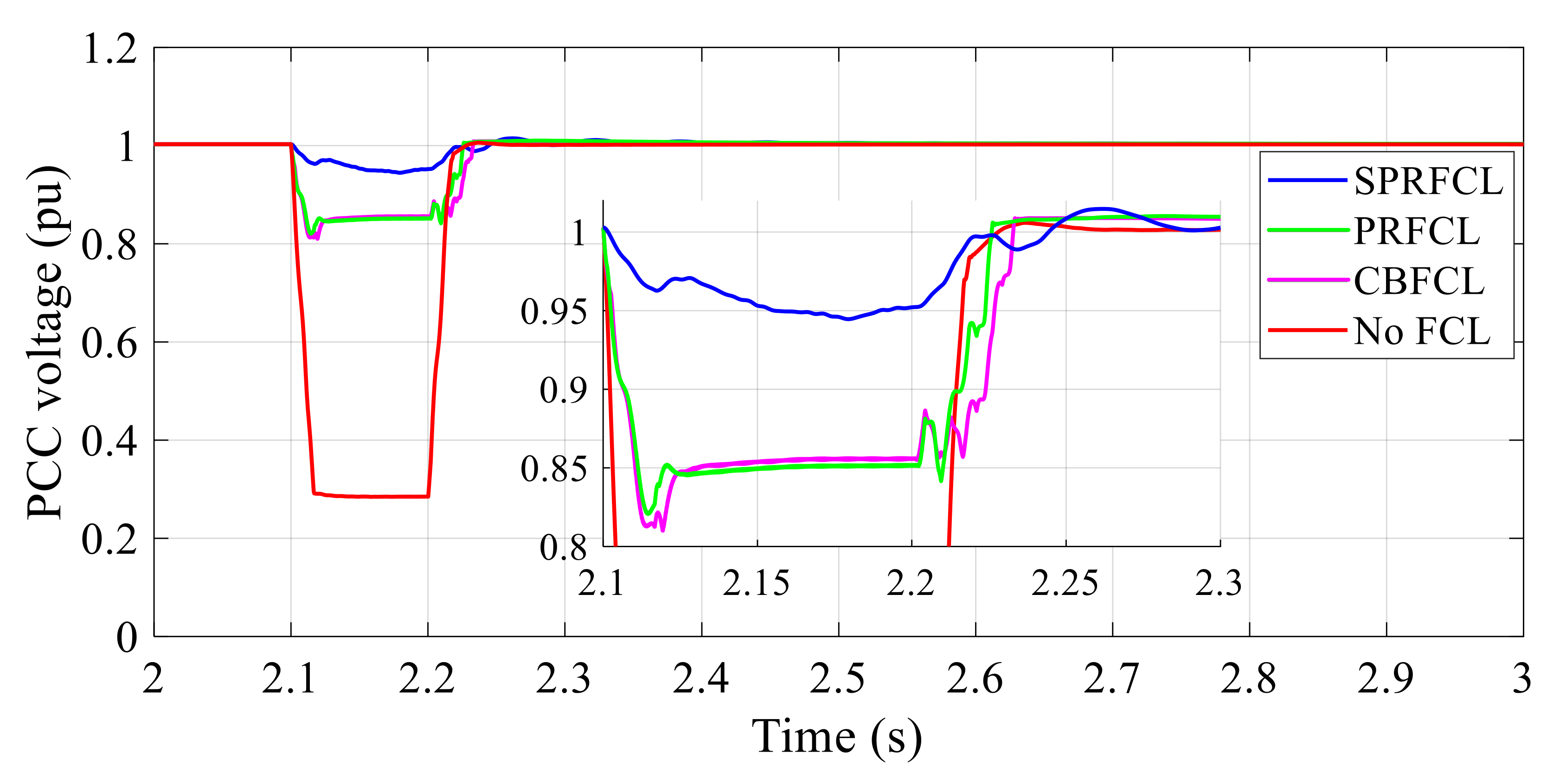
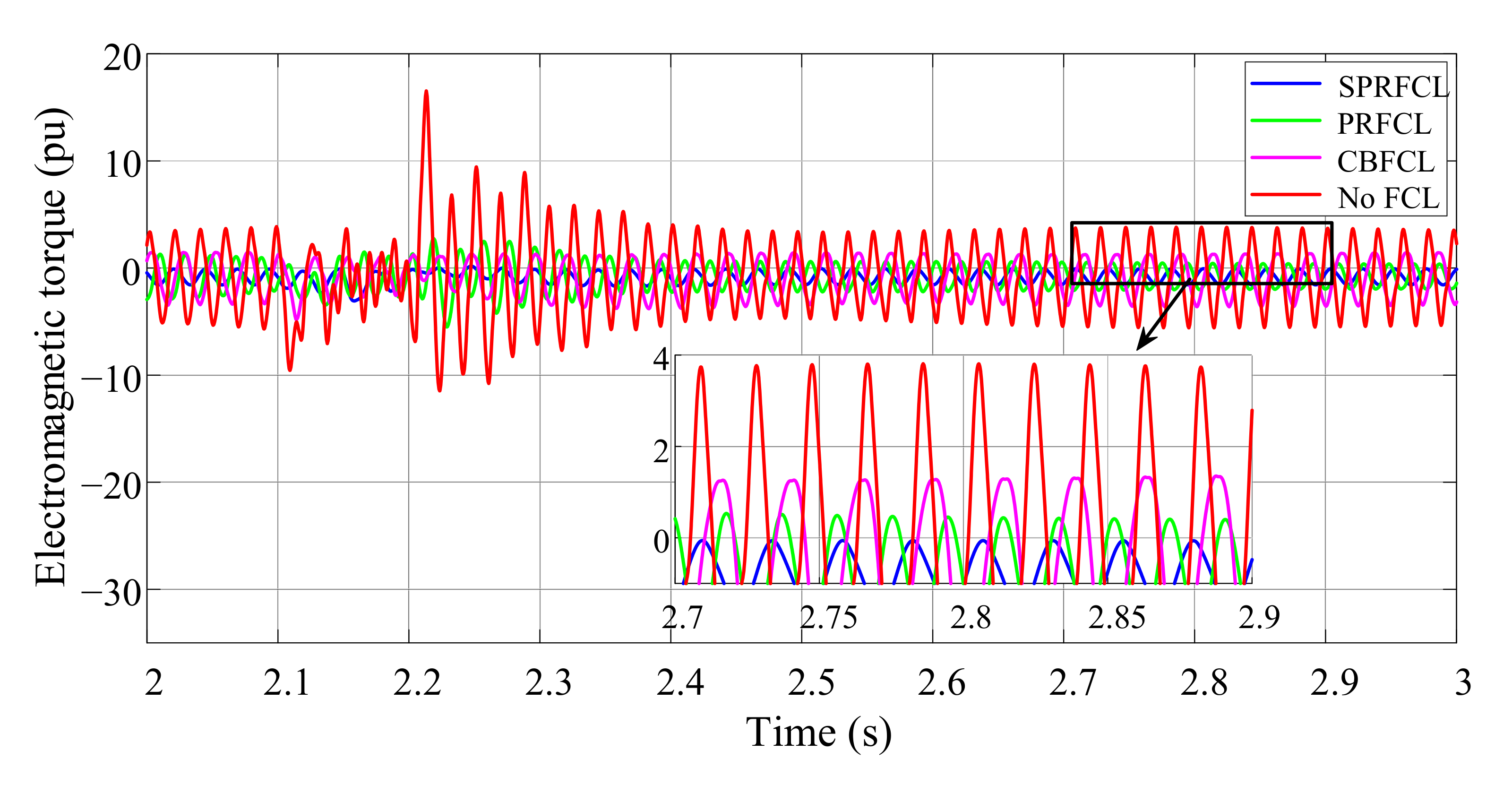
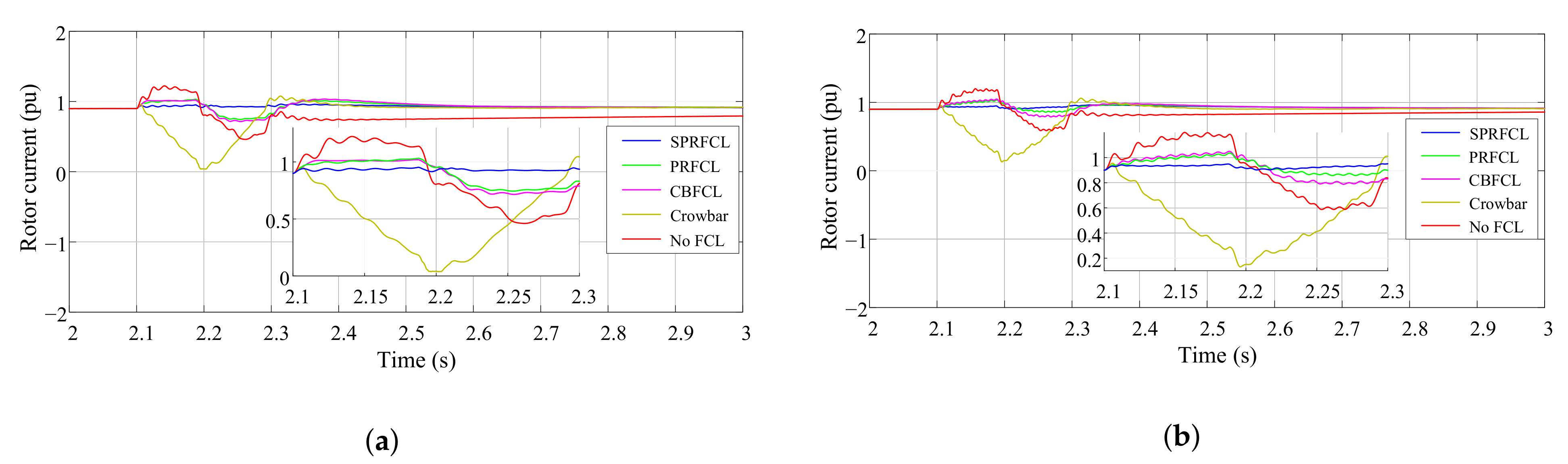
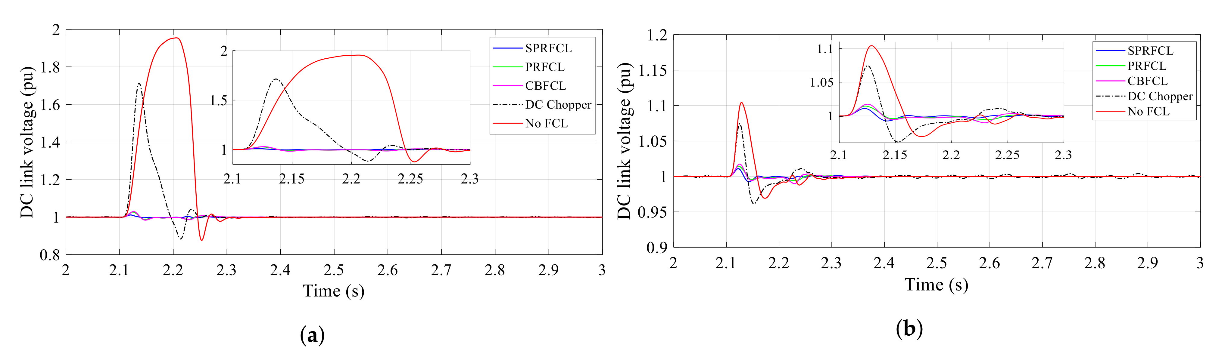
5.1. Graphical Analysis: Symmetrical Fault

From Figure 7, Figure 8, Figure 9, Figure 10, Figure 11, Figure 12 and Figure 13, the system responses for a symmetrical fault are demonstrated. The PCC voltage response suffers the worst consequences in case of no FCL as the voltage dips to zero and violates the grid code. The CBFCL and the PRFCL reduce this voltage sag to a considerable amount, and maintains the grid code properly as shown in Figure 7. However, the SPRFCL exhibits the best performance as it assures lower voltage sag during fault than the rests.
The active power response of the DFIG is illustrated in Figure 8. The active power reaches almost zero during fault without any FCL and maintains the per unit value higher than 1 pu even after clearing the fault. Although the CBFCL and the PRFCL guarantee overall lower sag and deviation in active power profile, they exhibit significant swell and dip just after the beginning and clearance of the fault. However, improved performance is achieved using SPRFCL, which minimizes the fluctuations and sag notably in the active power response.
In Figure 9, the DC link voltage profile of the DFIG is shown, where maximum deviation is observed without any FCL. Although both the CBFCL and PRFCL can keep the fluctuations within the permissible range, a greater reduction in oscillations is obtained by the utilization of SPRFCL. During the occurrence of fault, DFIG speed, as shown in Figure 10, deviates from the desired level and returns to the normal state a while after withdrawing the fault. Although the CBFCL and PRFCL do a great job in lowering the speed deviation, the SPRFCL sustains almost constant speed during the fault time span.
The rotor and stator current responses of DFIG are illustrated in Figure 11 and Figure 12, respectively. Without any FCL there emerges lots of spikes, and the current also diverges from the desired value. The overcurrent and spikes are responsible for the overheating of the DFIG and necessary power equipments. Therefore, proper protection is required to suppress these spikes. Application of the CBFCL and PRFCL has a great impact on reduction of these surges in both rotor and stator currents. They diminish the over current and unwanted spikes in current responses to some extent. However, the proposed SPRFCL outperforms its competitors by making the current responses smoother. The current responses are approximately identical during and after the fault owing to utilization of the SPRFCL. The electromagnetic torque spectrum is depicted in Figure 13. It is observed that the torque fluctuates much more without any FCL, whereas it is significantly lower for the case of CBFCL and PRFCL. However, the proposed SPRFCL mitigates these fluctuations remarkably and preserves almost constant electromagnetic torque during and after the fault.

5.2. Graphical Analysis: Asymmetrical Fault

Figure 14, Figure 15, Figure 16, Figure 17, Figure 18 and Figure 19 present several responses for an asymmetrical fault. Quite similar to the symmetrical fault, the PCC voltage profile is best preserved by the SPRFCL, followed by the CBFCL and the PRFCL, as shown in Figure 14. Similarly, the active power response, as shown in Figure 15, has the lowest amount of fluctuations with the SPRFCL. Although the CBFCL and PRFCL provide a far better active power response than that without any FCL, the SPRFCL exhibits overall better performance.
The SPRFCL reins over the CBFCL and PRFCL for other responses as well. The SPRFCL assures comparatively smoother DC link voltage profile, a more constant DFIG speed response, better rotor and stator current profiles, and overall improved electromagnetic torque response, as observed in Figure 16, Figure 17, Figure 18, Figure 19 and Figure 20.

5.3. Index-Based Analysis

In order to justify the performance of all the FCLs numerically, an index-based analysis of the major responses are carried out. Several indices, denoted as v l t ( p u . s ) , p o w ( p u . s ) , d c l i n k ( p u . s ) , s p d ( p u . s ) , r t r ( p u . s ) , s t r ( p u . s ) , and t o r q u e ( p u . s ) , are calculated with the help of the following mathematical expressions [12,43]:
v l t ( p u . s ) = 0 T Δ V d t
p o w ( p u . s ) = 0 T Δ P d t
d c l i n k ( p u . s ) = 0 T Δ V d c d t
s p d ( p u . s ) = 0 T Δ ω d t
r t r ( p u . s ) = 0 T Δ I r d t
s t r ( p u . s ) = 0 T Δ I s d t
t o r q u e ( p u . s ) = 0 T Δ T e m d t
where Δ V , Δ P , Δ V d c , Δ ω , Δ I r , Δ I s , and Δ T e m are the deviations of PCC voltage, active power, DC link voltage, DFIG speed, rotor current, stator current, and electromagnetic torque, respectively. The smaller the value of indices, the better the LVRT capability enhancement of the system, as they indicate deviations from the anticipated value. Table 1 and Table 2 show the computed indices for symmetrical and asymmetrical faults for all of the mentioned FCLs. In both types of faults, the SPRFCL scored the lowest for each type of indices compared to the PRFCL and the CBFCL, indicating its superiority numerically too.

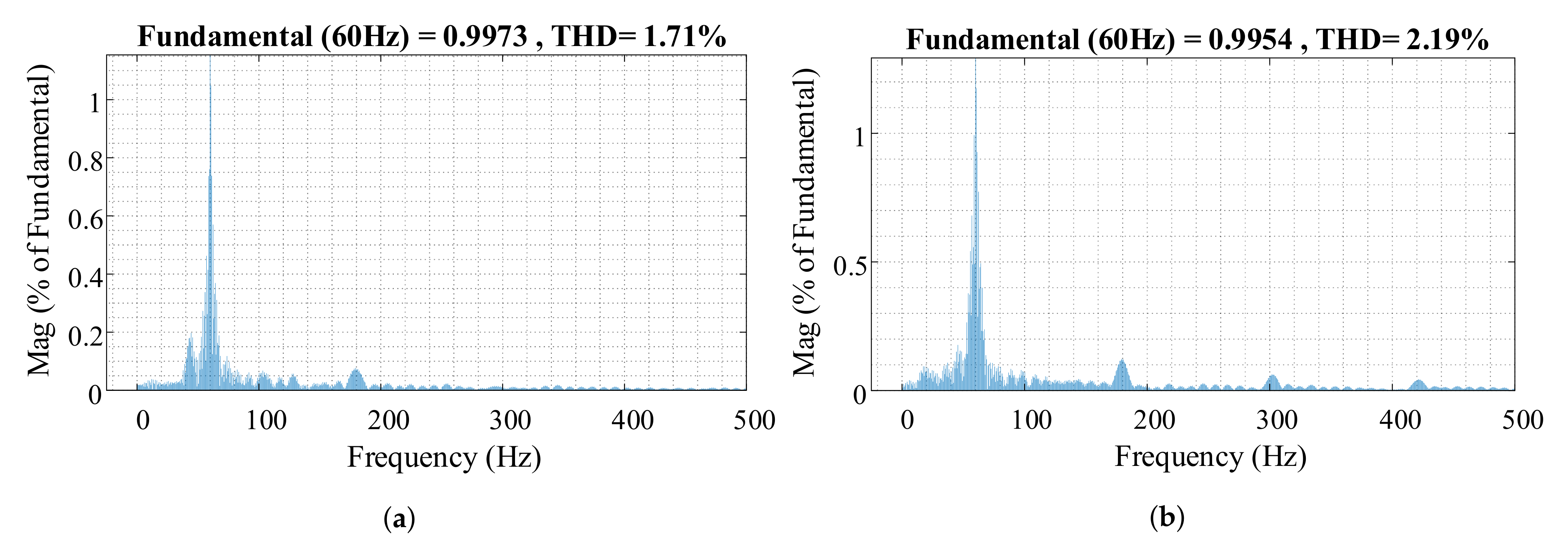
5.4. Total Harmonic Distortion (THD) Analysis

This subsection emphasizes the amount of THD present on the PCC voltage for each type of FCLs. Different nonlinearities emerge owing to grid disturbances, which result in harmonics and inter-harmonics in the current. Though series compensations are employed to mitigate the consequence of faults in the power system, different levels and orders of inter-harmonics remain in the spectrum. The IEEE 519-2014 standard sets a limitation on THD, that the percentage of THD must be within 5% before the injection of current to the utility grid. Therefore, a proper THD analysis is a prerequisite before installing the FCLs into the live grid.
The THD profiles of PCC voltages for both symmetrical and asymmetrical faults are displayed in Figure 21 and Figure 22, respectively. Among different FCLs, minimum THD is observed for the SPRFCL, that is 3.46% for symmetrical fault, complying with the IEEE standard by some margin. In the case of PRFCL and CBFCL, the percentage THD is lower than no FCL’s 17.93% to some extent. Their scores are 4.0% and 4.93% for the same symmetrical fault, higher than that of the SPRFCL. Therefore, both the CBFCL and PRFCL proved to be inferior to the SPRFCL for the overall health of the PCC voltage. Similar scenarios are observed for the asymmetrical fault as well, as shown in Figure 22. The SPRFCL kept the lowest THD profile compared to its counterparts by a significant margin.

5.5. Subsynchronous Resonance (SSR) Analysis

As the worldwide consumption of electrical energy is increasing every day, a large number of distributed generators (DGs) are being integrated to the grid. To support this the increased amount of power, the power transfer capability of existing transmission lines needed to be upgraded. Series compensation is a reliable way for expanding the power transfer capability of transmission lines, and it is accomplished by installing capacitor banks in series with the transmission line. This capacitive compensation not only increases power transfer capability, but also enhances transient voltage stability and controllability [23]. However, the expansion of power transfer capability comes at a cost as it gives rise to a phenomenon called subsynchronous resonance (SSR). This SSR results in torsional stress on the shaft of the turbine generator, which may damage the turbine in extreme case [46]. The risk of damage due to SSR becomes higher with the increase in the percentage of series capacitive compensation [46]. In this study, different compensation levels, for instance, 20%, 50%, 70%, and 90%, are considered for system without any FCL to study the spectrum of electromagnetic torque. Normally, the compensation is kept within 75%, but to observe the behaviour of electromagnetic torque in an extreme scenario, we considered 90% compensation in a symmetrical fault [47]. From Figure 23, it is observed that the torque oscillates more severely whenever the compensation level is 90%. Conversely, when the compensation is lower than 20%, the oscillations are at a minimum. In order to investigate the performance of different FCLs against transient SSR, 90% compensation is considered, and their outcomes are depicted in Figure 24. The SPRFCL shows the superior result as it damps the oscillations more precisely than its counterparts. Although the PRFCL performs better than the CBFCL and without any FCL in keeping the transient SSR minimum, their responses are still inferior to that of the SPRFCL.

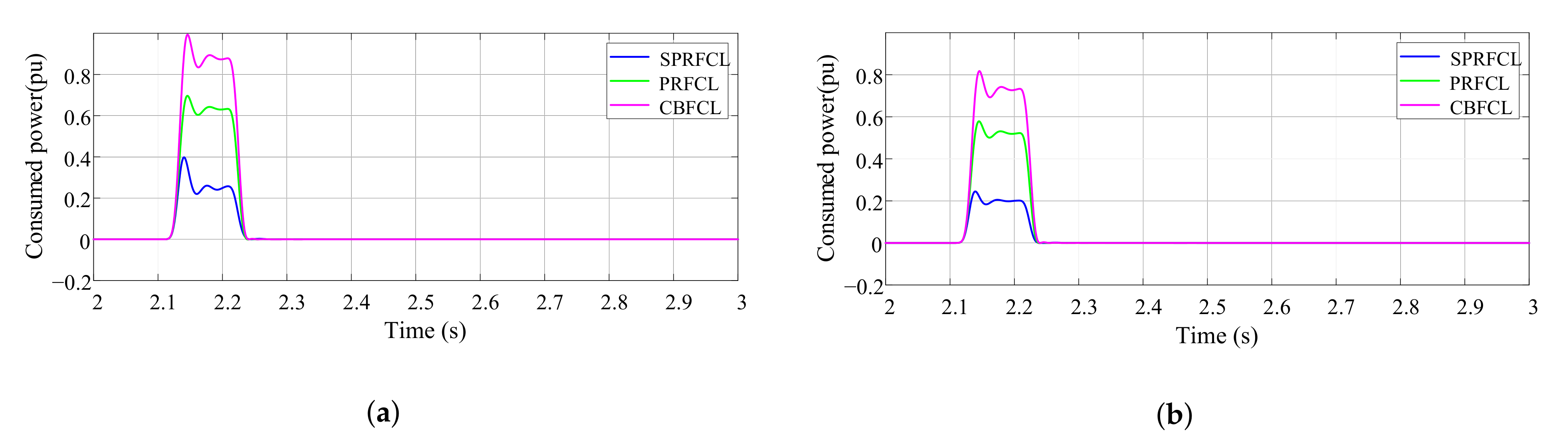
5.6. Power Consumption across the FCLs

Keeping the power consumption low across the FCLs under fault condition while maintaining overall good output responses is a challenging task. If more power dissipates through FCL, the system will get heated and will need larger power rated equipment. In Figure 25a, the absorbed power across the FCLs for symmetrical fault are presented. Explicitly, the SPRFCL consumes less power than the others. Under asymmetrical fault in Figure 25b, the same scenario is observed as the SPRFCL consumes the lowest power. Therefore, it is undoubtedly proved that the SPRFCL requires lower power ratings at any circumstance, which makes it more efficient in LVRT application.

5.7. Performance Comparison with Conventional LVRT Techniques

This section deals with comparison of some high-performance FCLs with conventional LVRT techniques. Conventional techniques like crowbar DC link choppers were studied decades ago and used for distinctive purposes. For instance, crowbar was proposed mainly to protect the RSC from overcurrent during fault [13,20]. It hardly improves the other DFIG responses except the rotor current. Similarly, a DC link chopper [14,48] was introduced for a specific purpose, that is, to keep the DC link voltage across the DC link capacitor at a permittable level. Therefore, the applications of these conventional schemes are confined to some specific objectives, and they only provide partial protection [36]. However, the various FCLs enhance the LVRT capability along with better output profiles of different responses providing complete protection against fault transients. Here, in Figure 26a,b, rotor current responses are shown for symmetrical and asymmetrical faults, respectively. These figures admit that crowbar diminishes the fault current properly and shows better response than the system without any FCL, whereas SPRFCL shows outstanding performances among all FCLs and crowbar systems. A similar observation is found for DC link chopper which restricts the DC link voltage increasing further during a fault and shows better output than the systems without any FCL, which are depicted in Figure 27a,b, respectively, for symmetrical and asymmetrical fault. However, this case also supports the superiority of the SPRFCL as it outweighs all its counterparts and DC chopper.

6. Economic Viewpoint of the Application of the SPRFCL

Apart from the SPRFCL, almost all FCLs in the current literature are of bridge type, which comprises a diode bridge circuit and inherent IGBT switch. The dynamic configuration of the SPRFCL does not need any bridge circuit for proper switching and thus it saves the cost of a bridge circuit. Furthermore, the bridge circuits incur power loss in the diodes. The SPRFCL is free from these losses too. If we observe the structure of the SPRFCL properly, we can find that the same inductor L C is being used to form series and parallel resonance, and so maximum utilization of existing components is achieved without increasing any cost. If we compare the SPRFCL circuit with that of the PRFCL and CBFCL, we notice that the cost of an additional capacitor in the SPRFCL is neutralized by the savings of not having any diode bridge circuit. Therefore, the SPRFCL can provide richer system responses than the PRFCL and CBFCL at lower cost.

7. Conclusions

In this paper, a high-performance series-parallel resonance-type fault current limiter (SPRFCL) is proposed for augmenting the LVRT capability of DFIG-based WF. The overall outcomes are investigated applying both symmetrical and asymmetrical faults, where the proposed SPRFCL shows the best result in every case. Several performance evaluation techniques like index-based analysis, percentage THD, and SSR analysis support the theoretical claims and proves the supremacy of the SPRFCL over the documented PRFCL and CBFCL. Going through all the simulation results as well as computational analysis, the following points are summarized.
  • The SPRFCL assures better overall voltage, current, power, speed, and torque profiles of the DFIG for both symmetrical and asymmetrical faults. The SPRFCL assures less perturbations in every response and provided better damping so as to make the settling time of each responses the lowest.
  • The SPRFCL scores the lowest in index-based analysis, indicating lower deviation in system responses. The SPRFCL has improved the PCC voltage by 87.79%, when compared to the voltage profile without any FCL during a symmetrical fault. The PRFCL and CBFCL have improvements of 78.36% and 71.47%, respectively, which are much lower than that of the SPRFCL. Similarly, the SPRFCL guarantees the highest improvement in PCC voltage during an asymmetrical fault as well, scoring 16.74% more than the PRFCL and 17.54% more than the CBFCL.
  • Better THD profiles and more reliable transient SSR responses are observed with the SPRFCL.
In future, the SPRFCL will be implemented for a larger power system to test its efficacy. Further, a nonlinear controller will be implemented to model adaptive impedance based on fault severity.

Author Contributions

Conceptualization, M.Y.-Y.U.H., J.H., and M.R.I. (Md. Rashidul Islam); methodology, M.R.I. (Md. Rashidul Islam); software, M.Y.-Y.U.H. and J.H.; validation, M.R.I. (Md. Rashidul Islam) and M.R.I. (Md. Rabiul Islam); formal analysis, M.Y.-Y.U.H., J.H., and M.R.I. (Md. Rashidul Islam); writing—original draft preparation, M.Y.-Y.U.H. and J.H.; writing—review and editing, M.R.I. (Md. Rashidul Islam) and M.R.I. (Md. Rabiul Islam); supervision, M.R.I. (Md. Rabiul Islam). All authors have read and agreed to the published version of the manuscript.

Funding

This research received no external funding.

Institutional Review Board Statement

Not applicable.

Informed Consent Statement

Not applicable.

Data Availability Statement

This publication is supported by multiple data sets, which are available at locations cited in the References section.

Conflicts of Interest

The authors declare no conflict of interest.

Abbreviations

The following abbreviations are used in this manuscript:
DFIG  Doubly fed induction generator
FCL  Fault current limiter
LVRT  Low-voltage ride-through capability
WF  Wind farm
DG  Distributed generator
PCC  Point of common coupling
RSC  Rotor side converter
GSC  Grid side converter
THD  Total harmonic distortion
SSR  Subsynchronous resonance
CBFCL  Capacitive bridge-type fault current limiter
PRFCL  Parallel resonance-type fault current limiter

Appendix A

The parameters of the DFIG and the drive train data are provided in Table A1.
Table A1. Each DFIG and drive train data.
ParameterValue
Rated power2 MW
Rated voltage575 V
DC-link nominal voltage1150 V
DC-link capacitance value10,000 μ F
Wind speed15 ms 1
Frequency60 Hz
Resistance of stator0.023 pu
Magnetizing inductance2.9 pu
Leakage inductance of stator0.18 pu
Inertia constant0.685
Leakage inductance of wound rotor0.16 pu
Wound rotor resistance0.016 pu
Friction factor0.01

References

  1. Haque, M.Y.Y.U.; Islam, M.R.; Hasan, J.; Sheikh, M.R.I. Negative Imaginary Theory-Based Proportional Resonant Controller for Voltage Control of Three-Phase Islanded Microgrid. J. Control Autom. Electr. Syst. 2021, 32, 214–226. [Google Scholar] [CrossRef]
  2. Owusu, P.A.; Asumadu-Sarkodie, S. A review of renewable energy sources, sustainability issues and climate change mitigation. Cogent Eng. 2016, 3, 1167990. [Google Scholar] [CrossRef]
  3. Fernández-Guillamón, A.; Das, K.; Cutululis, N.A.; Molina-García, Á. Offshore wind power integration into future power systems: Overview and trends. J. Mar. Sci. Eng. 2019, 7, 399. [Google Scholar] [CrossRef] [Green Version]
  4. Cardenas, R.; Peña, R.; Alepuz, S.; Asher, G. Overview of control systems for the operation of DFIGs in wind energy applications. IEEE Trans. Ind. Electron. 2013, 60, 2776–2798. [Google Scholar] [CrossRef]
  5. Islam, M.R.; Hasan, J.; Shipon, M.R.R.; Sadi, M.A.H.; Abuhussein, A.; Roy, T.K. Neuro Fuzzy Logic Controlled Parallel Resonance Type Fault Current Limiter to Improve the Fault Ride Through Capability of DFIG Based Wind Farm. IEEE Access 2020, 8, 115314–115334. [Google Scholar] [CrossRef]
  6. Uddin, W.; Zeb, K.; Tanoli, A.; Haider, A. Hardware-based hybrid scheme to improve the fault ride through capability of doubly fed induction generator under symmetrical and asymmetrical fault. IET Gener. Transm. Distrib. 2017, 12, 200–206. [Google Scholar] [CrossRef]
  7. Zhu, R.; Chen, Z.; Wu, X.; Deng, F. Virtual damping flux-based LVRT control for DFIG-based wind turbine. IEEE Trans. Energy Convers. 2015, 30, 714–725. [Google Scholar] [CrossRef]
  8. Mahdianpoor, M.; Kiyoumarsi, A.; Ataei, M.; Hooshmand, R.A. Robust implementation of distribution static compensator along with bridge type fault current limiter for fault ride through enhancement of fixed speed wind turbines. IEEE Access 2017, 5, 14490–14501. [Google Scholar] [CrossRef]
  9. Zhu, D.; Zou, X.; Deng, L.; Huang, Q.; Zhou, S.; Kang, Y. Inductance-emulating control for DFIG-based wind turbine to ride-through grid faults. IEEE Trans. Power Electron. 2016, 32, 8514–8525. [Google Scholar] [CrossRef]
  10. Firouzi, M.; Gharehpetian, G.B. LVRT performance enhancement of DFIG-based wind farms by capacitive bridge-type fault current limiter. IEEE Trans. Sustain. Energy 2017, 9, 1118–1125. [Google Scholar] [CrossRef]
  11. Islam, M.R.; Upadhay, A.D.; Roy, T.K.; Hasan, J.; Mahmud, M.A. Nonlinear backstepping controller design for bridge-type fault current limiter to enhance the transient performance of hybrid power systems. Int. Trans. Electr. Energy Syst. 2021, e13097. [Google Scholar] [CrossRef]
  12. Rashid, G.; Ali, M.H. Fault ride through capability improvement of DFIG based wind farm by fuzzy logic controlled parallel resonance fault current limiter. Electr. Power Syst. Res. 2017, 146, 1–8. [Google Scholar] [CrossRef]
  13. Morren, J.; De Haan, S.W. Ridethrough of wind turbines with doubly-fed induction generator during a voltage dip. IEEE Trans. Energy Convers. 2005, 20, 435–441. [Google Scholar] [CrossRef] [Green Version]
  14. Pannell, G.; Zahawi, B.; Atkinson, D.J.; Missailidis, P. Evaluation of the performance of a DC-link brake chopper as a DFIG low-voltage fault-ride-through device. IEEE Trans. Energy Convers. 2013, 28, 535–542. [Google Scholar] [CrossRef]
  15. Moon, W.S.; Won, J.N.; Huh, J.S.; Kim, J.C. A study on the application of a superconducting fault current limiter for energy storage protection in a power distribution system. IEEE Trans. Appl. Supercond. 2013, 23, 5603404. [Google Scholar] [CrossRef]
  16. Truong, D.N.; Ngo, V.T. Designed damping controller for SSSC to improve stability of a hybrid offshore wind farms considering time delay. Int. J. Electr. Power Energy Syst. 2015, 65, 425–431. [Google Scholar] [CrossRef]
  17. Yang, J.; Fletcher, J.E.; O’Reilly, J. A series-dynamic-resistor-based converter protection scheme for doubly-fed induction generator during various fault conditions. IEEE Trans. Energy Convers. 2010, 25, 422–432. [Google Scholar] [CrossRef] [Green Version]
  18. Wang, L.; Truong, D.N. Stability Enhancement of DFIG-Based Offshore Wind Farm Fed to a Multi-Machine System Using a STATCOM. IEEE Trans. Power Syst. 2013, 28, 2882–2889. [Google Scholar] [CrossRef]
  19. Firouzi, M.; Gharehpetian, G.B.; Mozafari, B. Power-flow control and short-circuit current limitation of wind farms using unified interphase power controller. IEEE Trans. Power Deliv. 2016, 32, 62–71. [Google Scholar] [CrossRef]
  20. Okedu, K.; Muyeen, S.; Takahashi, R.; Tamura, J. Comparative study between two protection schemes for DFIG-based wind generator. In Proceedings of the 2010 International Conference on Electrical Machines and Systems, IEEE, Incheon, Korea, 10–13 October 2010; pp. 62–67. [Google Scholar]
  21. Salles, M.; Cardoso, J.; Grilo, A.; Rahmann, C.; Hameyer, K. Control strategies of doubly fed induction generators to support grid voltage. In Proceedings of the 2009 IEEE International Electric Machines and Drives Conference, IEEE, Miami, FL, USA, 3–6 May 2009; pp. 1551–1556. [Google Scholar]
  22. Islam, M.; Huda, M.; Hasan, J.; Sadi, M.A.H.; AbuHussein, A.; Roy, T.K.; Mahmud, M. Fault Ride Through Capability Improvement of DFIG Based Wind Farm Using Nonlinear Controller Based Bridge-Type Flux Coupling Non-Superconducting Fault Current Limiter. Energies 2020, 13, 1696. [Google Scholar] [CrossRef] [Green Version]
  23. Islam, M.R.; Hasan, J.; Hasan, M.M.; Huda, M.N.; Sadi, M.A.H.; AbuHussein, A. Performance improvement of DFIG-based wind farms using NARMA-L2 controlled bridge-type flux coupling non-superconducting fault current limiter. IET Gener. Transm. Distrib. 2021, 14, 6580–6593. [Google Scholar] [CrossRef]
  24. Asghar, R. Fault current limiters types, operations and its limitations. Int. J. Sci. Eng. Res. 2018, 9, 1020–1027. [Google Scholar]
  25. Hasan, J.; Islam, M.R.; Islam, M.R.; Kouzani, A.Z.; Mahmud, M.P. A Capacitive Bridge-Type Superconducting Fault Current Limiter to Improve the Transient Performance of DFIG/PV/SG-Based Hybrid Power System. IEEE Trans. Appl. Supercond. 2021, 31, 1–5. [Google Scholar] [CrossRef]
  26. Islam, M.R.; Hasan, J.; Islam, M.R.; Kouzani, A.Z.; Mahmud, M.P. Transient Performance Augmentation of DFIG Based Wind Farms by Nonlinear Control of Flux-Coupling-Type Superconducting Fault Current Limiter. IEEE Trans. Appl. Supercond. 2021, 31, 1–5. [Google Scholar] [CrossRef]
  27. Chen, L.; Chen, H.; Yang, J.; Yu, Y.; Zhen, K.; Liu, Y.; Ren, L. Coordinated control of superconducting fault current limiter and superconducting magnetic energy storage for transient performance enhancement of grid-connected photovoltaic generation system. Energies 2017, 10, 56. [Google Scholar] [CrossRef] [Green Version]
  28. Kim, C.; Lee, K.; Ryu, K. A numerical study on temperature increase in the resistive SFCL element due to the quench condition. IEEE Trans. Appl. Supercond. 2006, 16, 636–641. [Google Scholar] [CrossRef]
  29. Chen, L.; He, H.; Li, G.; Chen, H.; Wang, L.; Chen, X.; Tian, X.; Xu, Y.; Ren, L.; Tang, Y. Study of resistive-type superconducting fault current limiters for a hybrid high voltage direct current system. Materials 2019, 12, 26. [Google Scholar] [CrossRef] [Green Version]
  30. Islam, M.R.; Abir, D.D.; Islam, M.R.; Hasan, J.; Huda, M.N.; Muttaqi, K.M.; Sutanto, D. Enhancement of FRT Capability of DFIG Based Wind Farm by a Hybrid Superconducting Fault Current Limiter With Bias Magnetic Field. In Proceedings of the 2020 IEEE International Conference on Power Electronics, Smart Grid and Renewable Energy (PESGRE2020), Kerala, India, 2–4 January 2020; pp. 1–6. [Google Scholar]
  31. Safaei, A.; Zolfaghari, M.; Gilvanejad, M.; Gharehpetian, G.B. A survey on fault current limiters: Development and technical aspects. Int. J. Electr. Power Energy Syst. 2020, 118, 105729. [Google Scholar] [CrossRef]
  32. Firouzi, M.; Gharehpetian, G. Improving fault ride-through capability of fixed-speed wind turbine by using bridge-type fault current limiter. IEEE Trans. Energy Convers. 2013, 28, 361–369. [Google Scholar] [CrossRef]
  33. Okedu, K.E.; Muyeen, S.; Takahashi, R.; Tamura, J. Wind farms fault ride through using DFIG with new protection scheme. IEEE Trans. Sustain. Energy 2012, 3, 242–254. [Google Scholar] [CrossRef] [Green Version]
  34. Ghanbari, T.; Farjah, E.; Zandnia, A. Development of a high-performance bridge-type fault current limiter. IET Gener. Transm. Distrib. 2013, 8, 486–494. [Google Scholar] [CrossRef]
  35. Rashid, G.; Ali, M.H. A modified bridge-type fault current limiter for fault ride-through capacity enhancement of fixed speed wind generator. IEEE Trans. Energy Convers. 2014, 29, 527–534. [Google Scholar]
  36. Padmaja, A.; Shanmukh, A.; Mendu, S.S.; Devarapalli, R.; Serrano González, J.; García Márquez, F.P. Design of Capacitive Bridge Fault Current Limiter for Low-Voltage Ride-Through Capacity Enrichment of Doubly Fed Induction Generator-Based Wind Farm. Sustainability 2021, 13, 6656. [Google Scholar] [CrossRef]
  37. Moghimian, M.M.; Radmehr, M.; Firouzi, M. Series resonance fault current limiter (SRFCL) with MOV for LVRT enhancement in DFIG-based wind farms. Electr. Power Compon. Syst. 2019, 47, 1814–1825. [Google Scholar] [CrossRef]
  38. Rezaee, M.; Harley, R.G. Resonance-based fault current limiters: Theory, applications, and assessment. IEEE Trans. Ind. Appl. 2018, 54, 3066–3076. [Google Scholar] [CrossRef]
  39. Naderi, S.B.; Jafari, M.; Hagh, M.T. Parallel-resonance-type fault current limiter. IEEE Trans. Ind. Electron. 2012, 60, 2538–2546. [Google Scholar] [CrossRef] [Green Version]
  40. Hossain, M.K.; Ali, M.H. Transient stability augmentation of PV/DFIG/SG-based hybrid power system by parallel-resonance bridge fault current limiter. Electr. Power Syst. Res. 2016, 130, 89–102. [Google Scholar] [CrossRef]
  41. Arikan, O.; Kucukaydin, B. A new approach to limit fault current with series–parallel resonance strategy. Electr. Eng. 2020, 102, 1287–1296. [Google Scholar] [CrossRef]
  42. Tian, X.; Li, G.; Chi, Y.; Wang, W.; Tang, H.; Li, X. Voltage phase angle jump characteristic of DFIGs in case of weak grid connection and grid fault. J. Mod. Power Syst. Clean Energy 2016, 4, 256–264. [Google Scholar] [CrossRef] [Green Version]
  43. Rashid, G.; Ali, M.H. Transient stability enhancement of doubly fed induction machine-based wind generator by bridge-type fault current limiter. IEEE Trans. Energy Convers. 2015, 30, 939–947. [Google Scholar] [CrossRef]
  44. Chapman, S.J. Electric Machinery and Power System Fundamentals; McGraw-Hill Science Engineering: New York, NY, USA, 2002. [Google Scholar]
  45. Morren, J.; De Haan, S.; Bauer, P.; Pierik, J.; Bozelie, J. Comparison of complete and reduced models of a wind turbine with doubly-fed induction generator. In Proceedings of the 10th European Conference on Power Electronics and Applications, EPE, Toulouse, France, 2–4 September 2003; pp. 1–10. [Google Scholar]
  46. Virulkar, V.; Gotmare, G. Sub-synchronous resonance in series compensated wind farm: A review. Renew. Sustain. Energy Rev. 2016, 55, 1010–1029. [Google Scholar] [CrossRef]
  47. Golshannavaz, S.; Aminifar, F.; Nazarpour, D. Application of UPFC to enhancing oscillatory response of series-compensated wind farm integrations. IEEE Trans. Smart Grid 2014, 5, 1961–1968. [Google Scholar] [CrossRef]
  48. Islam, M.R.; Ajom, M.G.; Sheikh, M. Application of DC chopper to augment fault ride through of DFIG based wind turbine. In Proceedings of the 2017 2nd International Conference on Electrical & Electronic Engineering (ICEEE), Rajshahi, Bangladesh, 27–29 December 2017; pp. 1–4. [Google Scholar]
Figure 1. General circuit for series-parallel resonance-type fault current limiter.
Wind 01 00002 g001
Figure 2. Control circuit for the SPRFCL, CBFCL, and PRFCL.
Wind 01 00002 g002
Figure 3. Architecture of the CBFCL.
Wind 01 00002 g003
Figure 4. Architecture of the PRFCL.
Wind 01 00002 g004
Figure 5. Schematic diagram of the complete DFIG-based wind farm.
Wind 01 00002 g005
Figure 6. DFIG-equivalent circuit.
Wind 01 00002 g006
Figure 7. PCC voltage response for symmetrical fault.
Wind 01 00002 g007
Figure 8. Active power response for symmetrical fault.
Wind 01 00002 g008
Figure 9. DC link voltage response for symmetrical fault.
Wind 01 00002 g009
Figure 10. DFIG speed response for symmetrical fault.
Wind 01 00002 g010
Figure 11. Rotor current response for symmetrical fault.
Wind 01 00002 g011
Figure 12. Stator current response for symmetrical fault.
Wind 01 00002 g012
Figure 13. Electromagnetic torque response for symmetrical fault.
Wind 01 00002 g013
Figure 14. PCC voltage response for asymmetrical fault.
Wind 01 00002 g014
Figure 15. Active power response for asymmetrical fault.
Wind 01 00002 g015
Figure 16. DC link voltage response for asymmetrical fault.
Wind 01 00002 g016
Figure 17. DFIG speed response for asymmetrical fault.
Wind 01 00002 g017
Figure 18. Rotor current response for asymmetrical fault.
Wind 01 00002 g018
Figure 19. Electromagnetic torque response for asymmetrical fault.
Wind 01 00002 g019
Figure 20. Stator current response for asymmetrical fault.
Wind 01 00002 g020
Figure 21. Percentage THD of the PCC voltage during symmetrical fault for the (a) SPRFCL, (b) PRFCL, (c) CBFCL, and (d) No FCL.
Wind 01 00002 g021
Figure 22. Percentage THD of the PCC voltage during asymmetrical fault for the (a) SPRFCL and (b) PRFCL.
Wind 01 00002 g022
Figure 23. Electromagnetic torque responses for different level of series compensation.
Wind 01 00002 g023
Figure 24. Electromagnetic torque responses of different FCLs for 90% series compensation.
Wind 01 00002 g024
Figure 25. Consumed power across the FCLs for the (a) symmetrical fault and (b) asymmetrical fault.
Wind 01 00002 g025
Figure 26. Rotor current profile for (a) symmetrical fault and (b) asymmetrical fault.
Wind 01 00002 g026
Figure 27. DC link voltage profile for (a) symmetrical fault and (b) asymmetrical fault.
Wind 01 00002 g027
Table 1. Performance indices for symmetrical fault.
Index Parameters (%)No FCLCBFCLPRFCLSPRFCL
vlt(pu.s)10.3302.9472.2351.313
pow(pu.s)15.8335.7172.7382.085
dclink(pu.s)9.0230.1490.1200.053
spd(pu.s)0.3102.8760.4060.140
rtr(pu.s)10.8077.2306.1883.375
str(pu.s)8.5916.8025.5791.377
torque(pu.s)17.7628.3977.7792.439
Table 2. Performance indices for asymmetrical fault.
Index Parameters (%)No FCLCBFCLPRFCLSPRFCL
vlt(pu.s)7.3772.1992.1410.906
pow(pu.s)10.7354.1313.2331.591
dclink(pu.s)0.3930.0850.0620.044
spd(pu.s)1.7570.2570.2490.085
rtr(pu.s)5.8815.0364.2922.189
str(pu.s)7.3764.3713.6231.468
torque(pu.s)15.1297.5476.3872.894
Publisher’s Note: MDPI stays neutral with regard to jurisdictional claims in published maps and institutional affiliations.

