
The Stibium Bond or the Antimony-Centered Pnictogen Bond: The Covalently Bound Antimony Atom in Molecular Entities in Crystal Lattices as a Pnictogen Bond Donor


Abstract
:1. Introduction
2. Antimony in Molecular Entities, Materials Design and Discovery
3. Inter- or Intramolecular Bond Distance and Less Than the Sum of the van der Waals Radii Concept
4. Directionality of Inter-/Intra-Molecular Interactions
5. The σ-Hole and π-Hole Concepts, and Their Relationship with Pnictogen Bonds
6. Model Systems and Computational Approaches
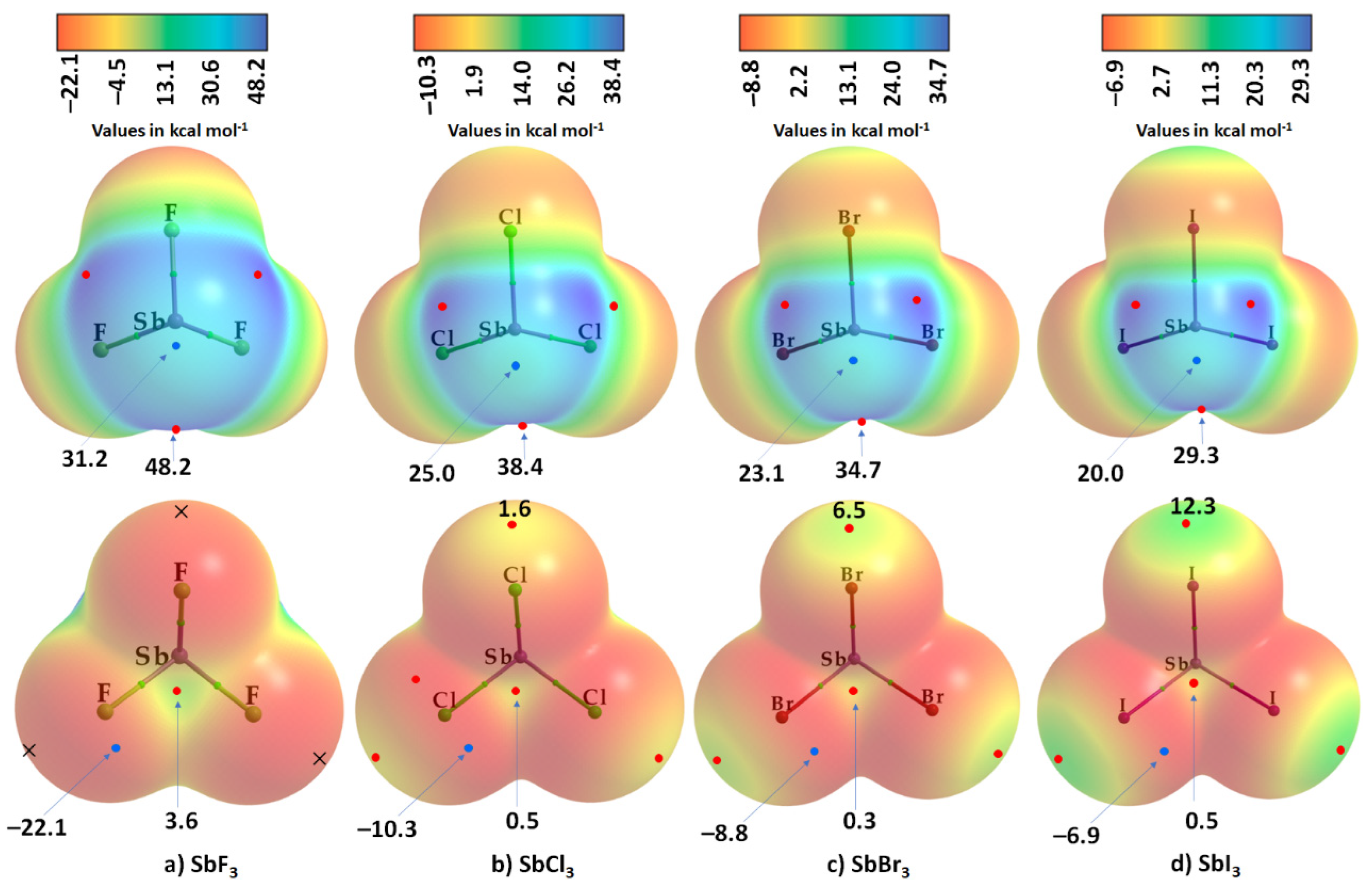
7. The Molecular Electrostatic Potential and Characterization of σ- and π-Holes in Molecular Entities
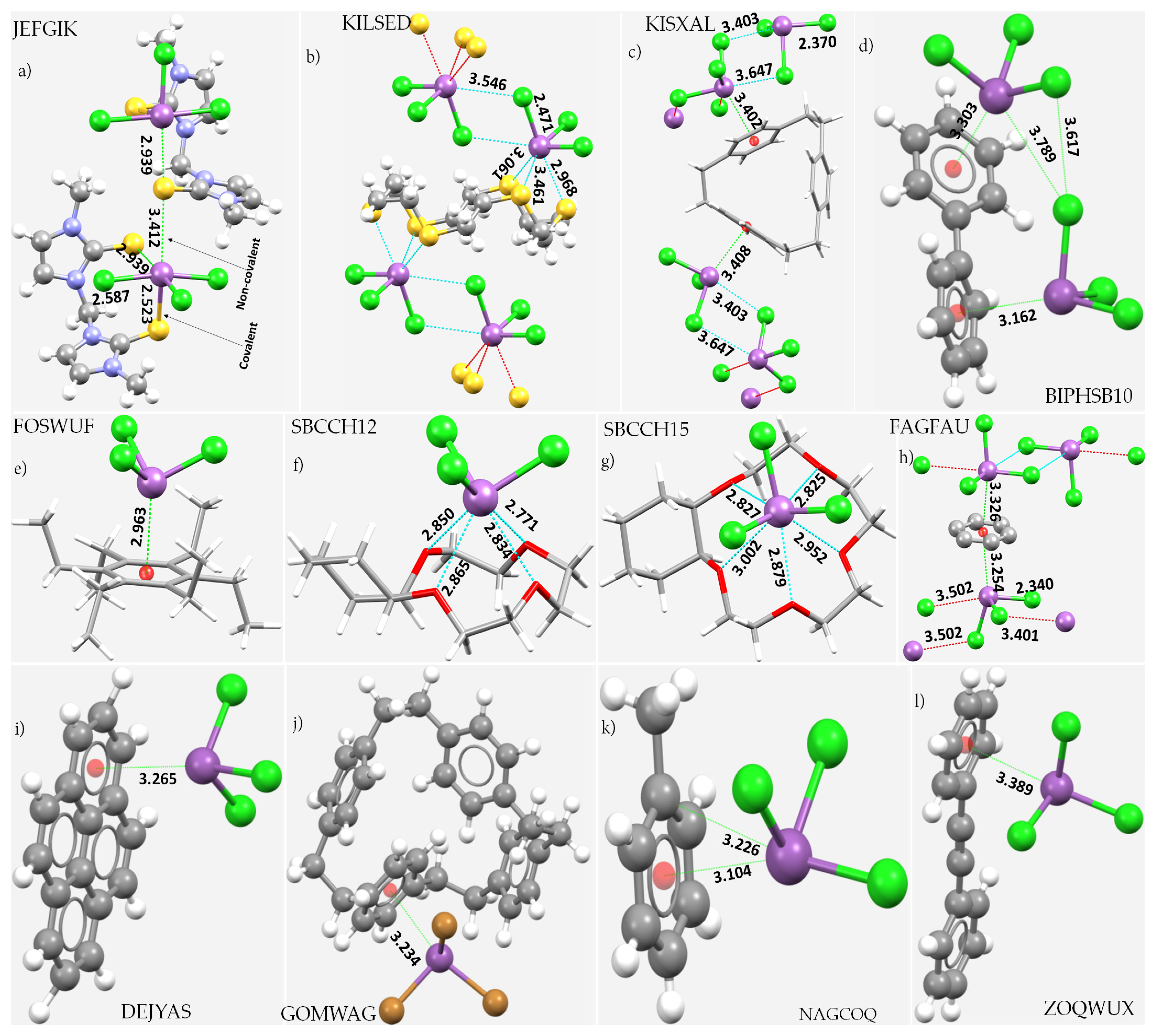
8. Illustrative Crystal Systems
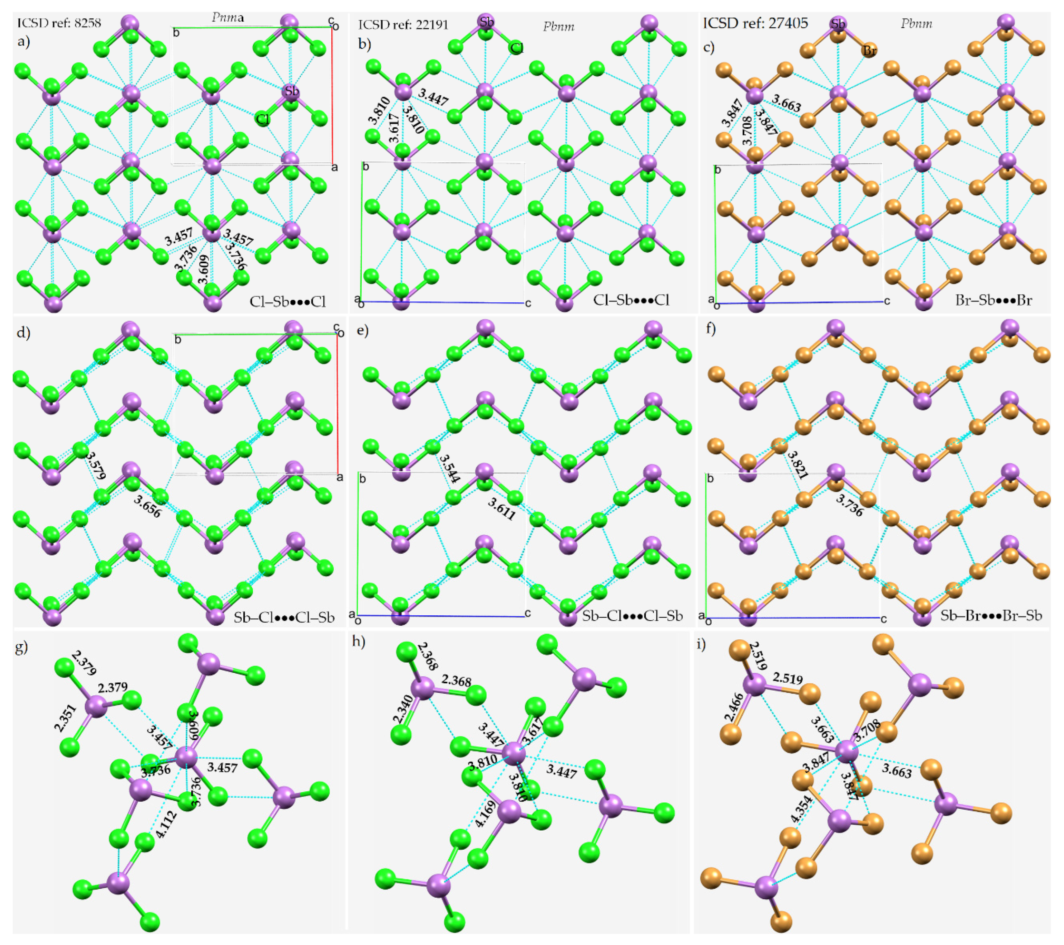
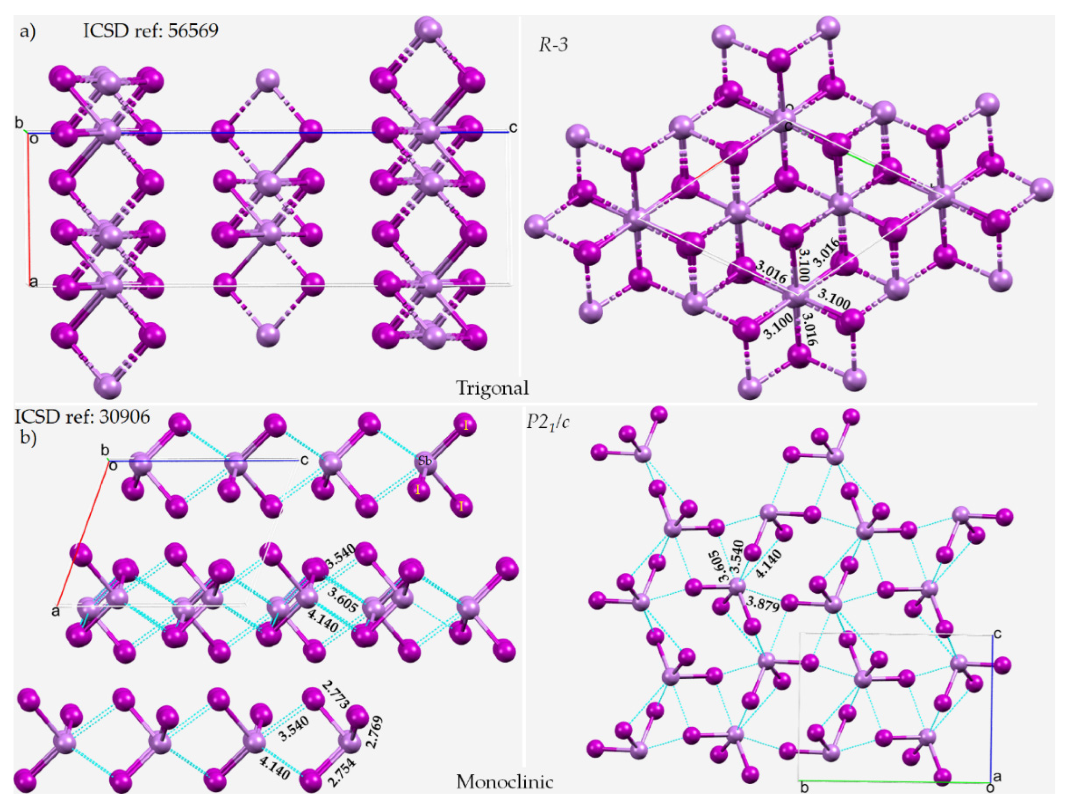
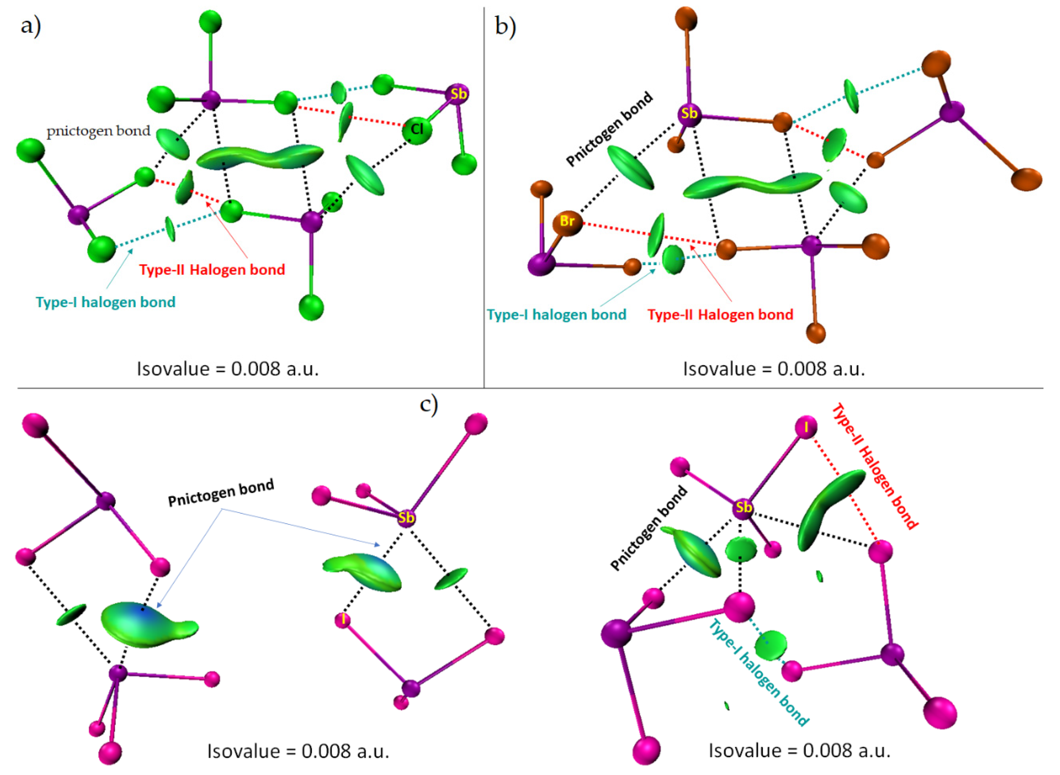
8.1. Antimony Trihalides
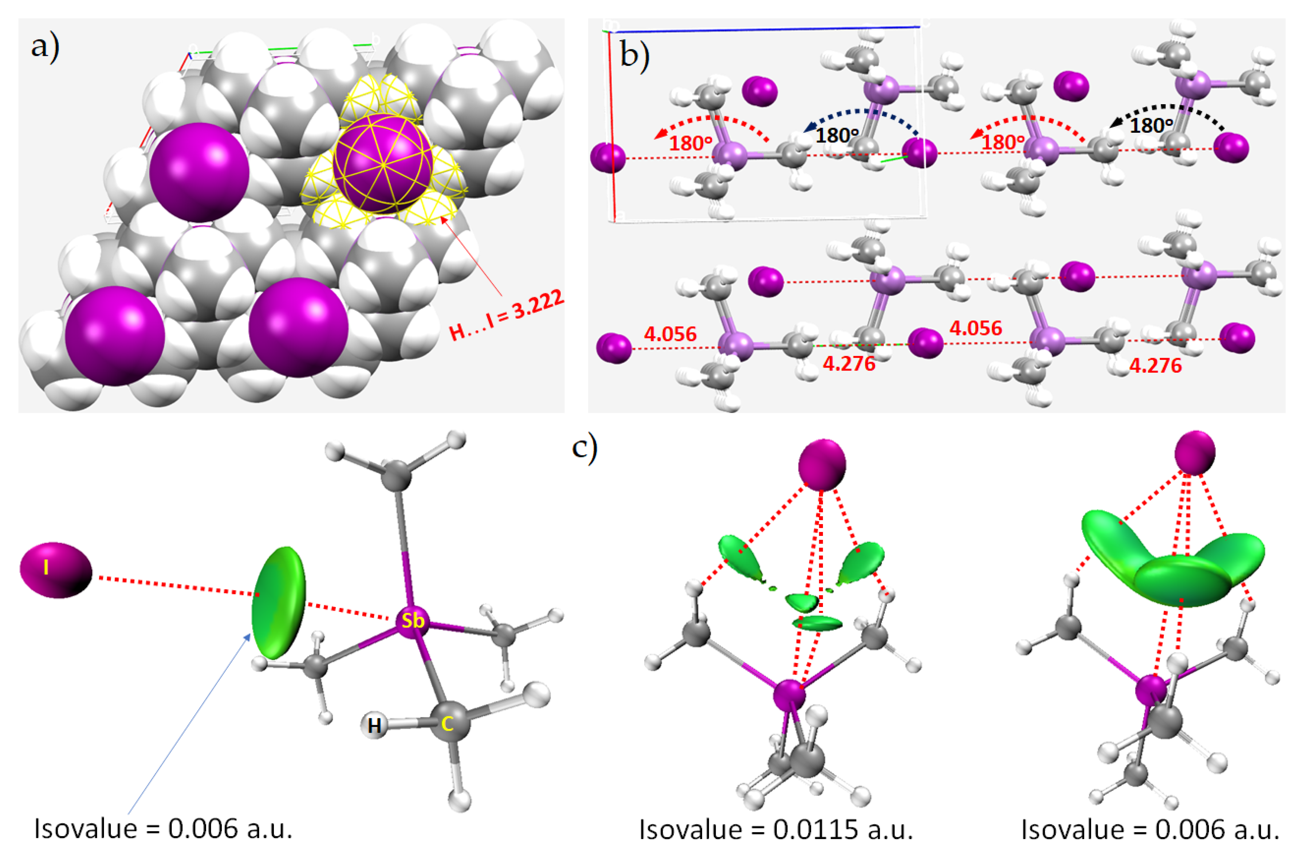
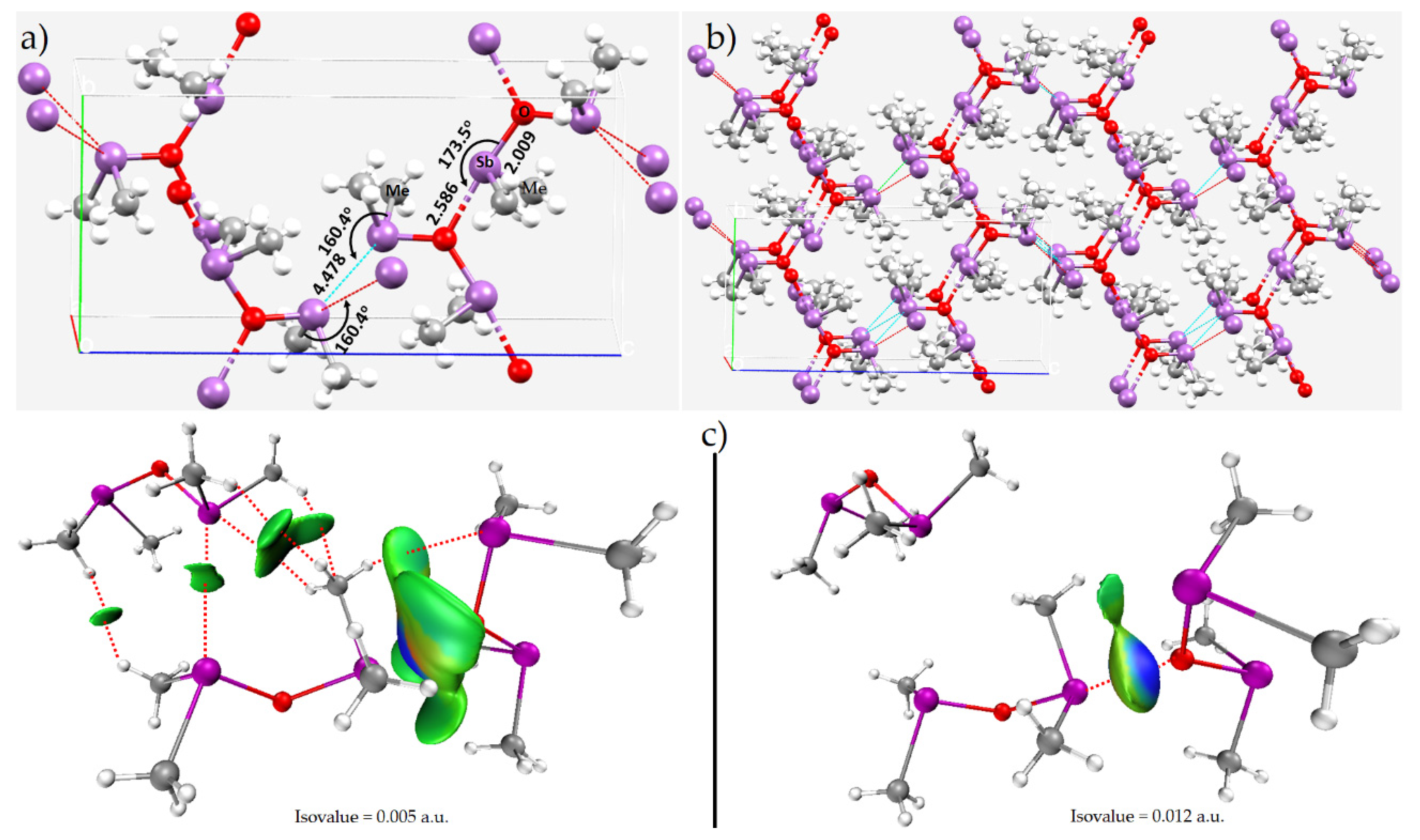
8.2. Tetramethyl-Antimony Iodide
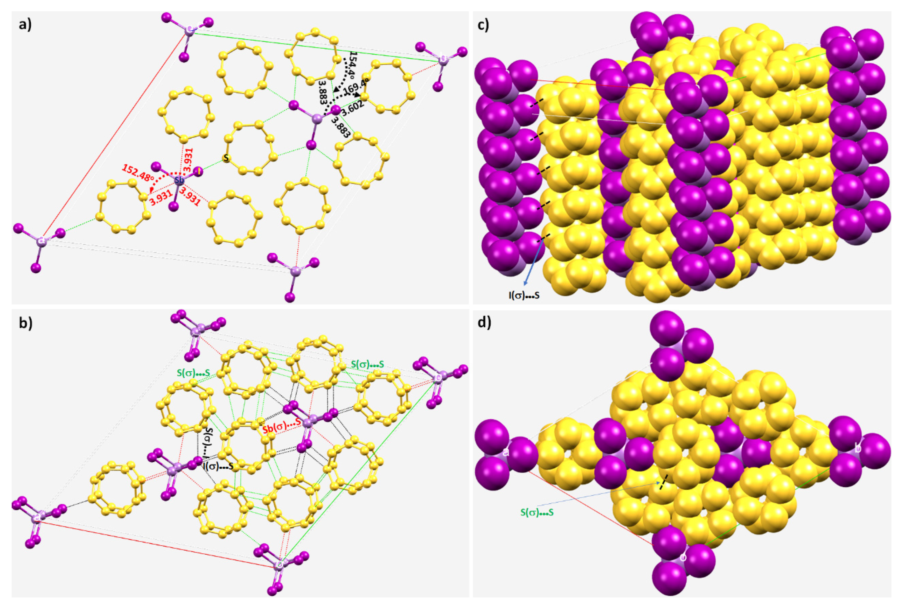
8.3. The Co-Crystal of Antimony Trihalide and Molecular Sulfur
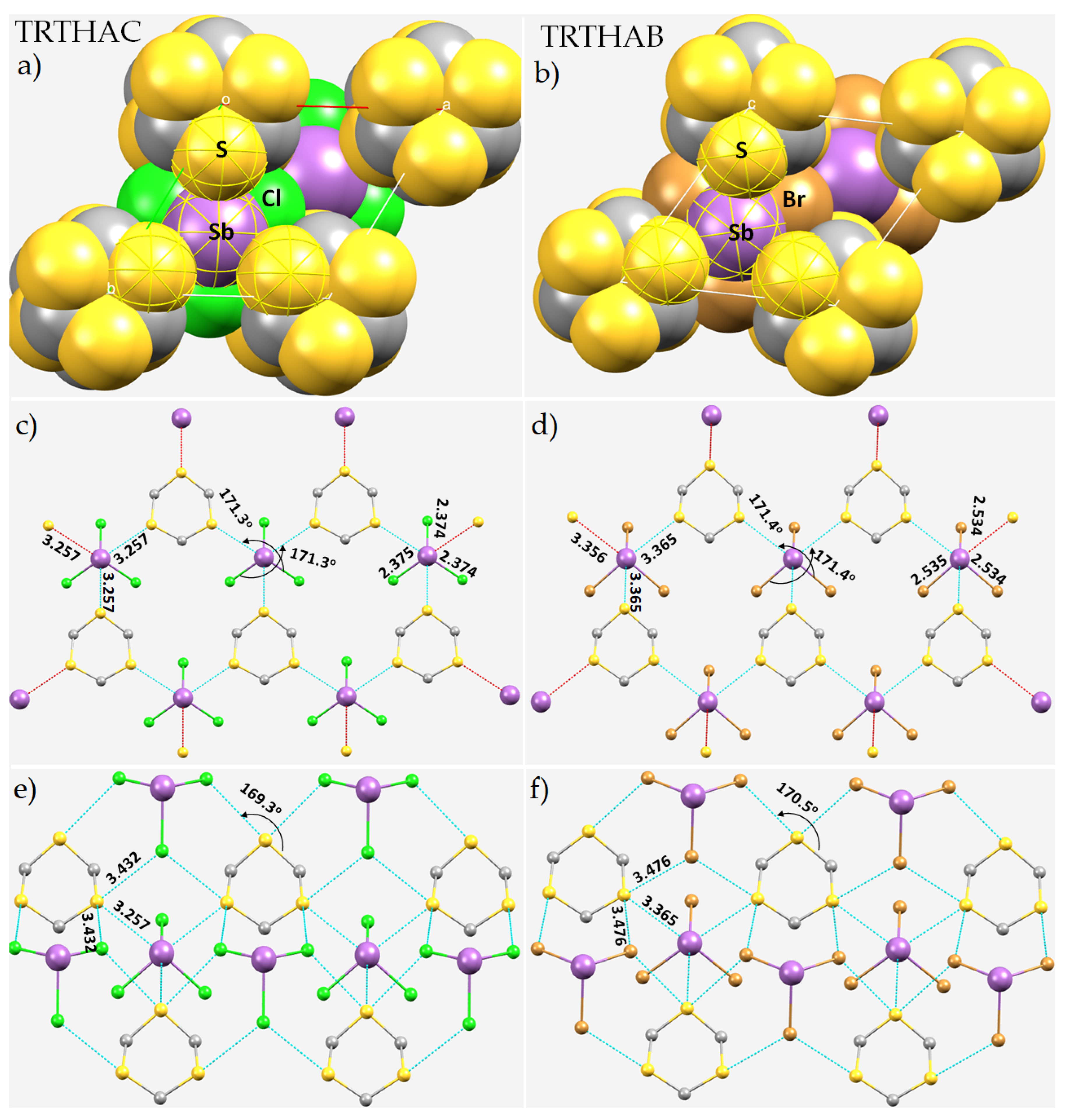
8.4. Antimony Trihalide Crystals
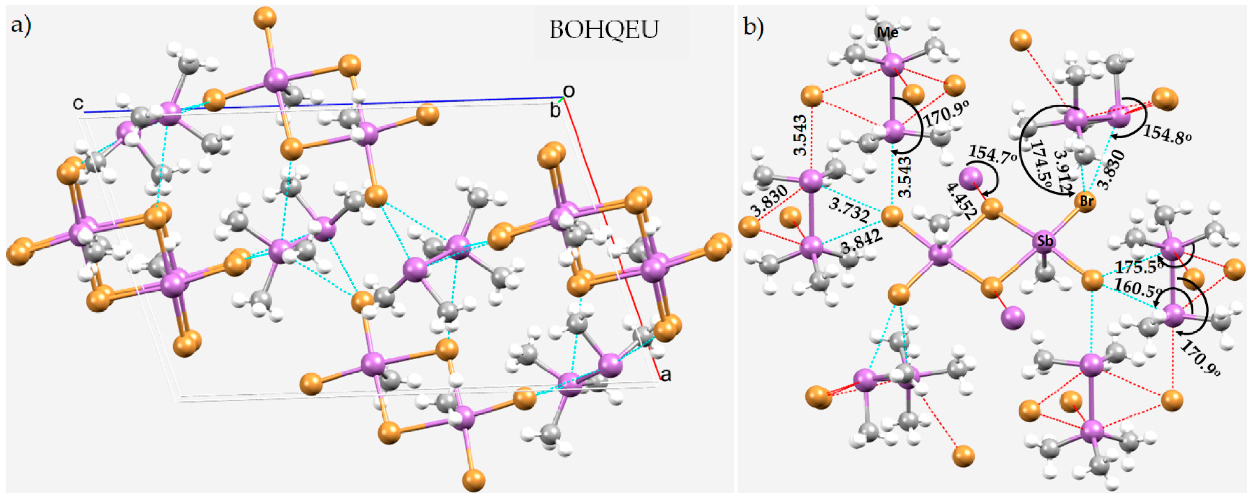
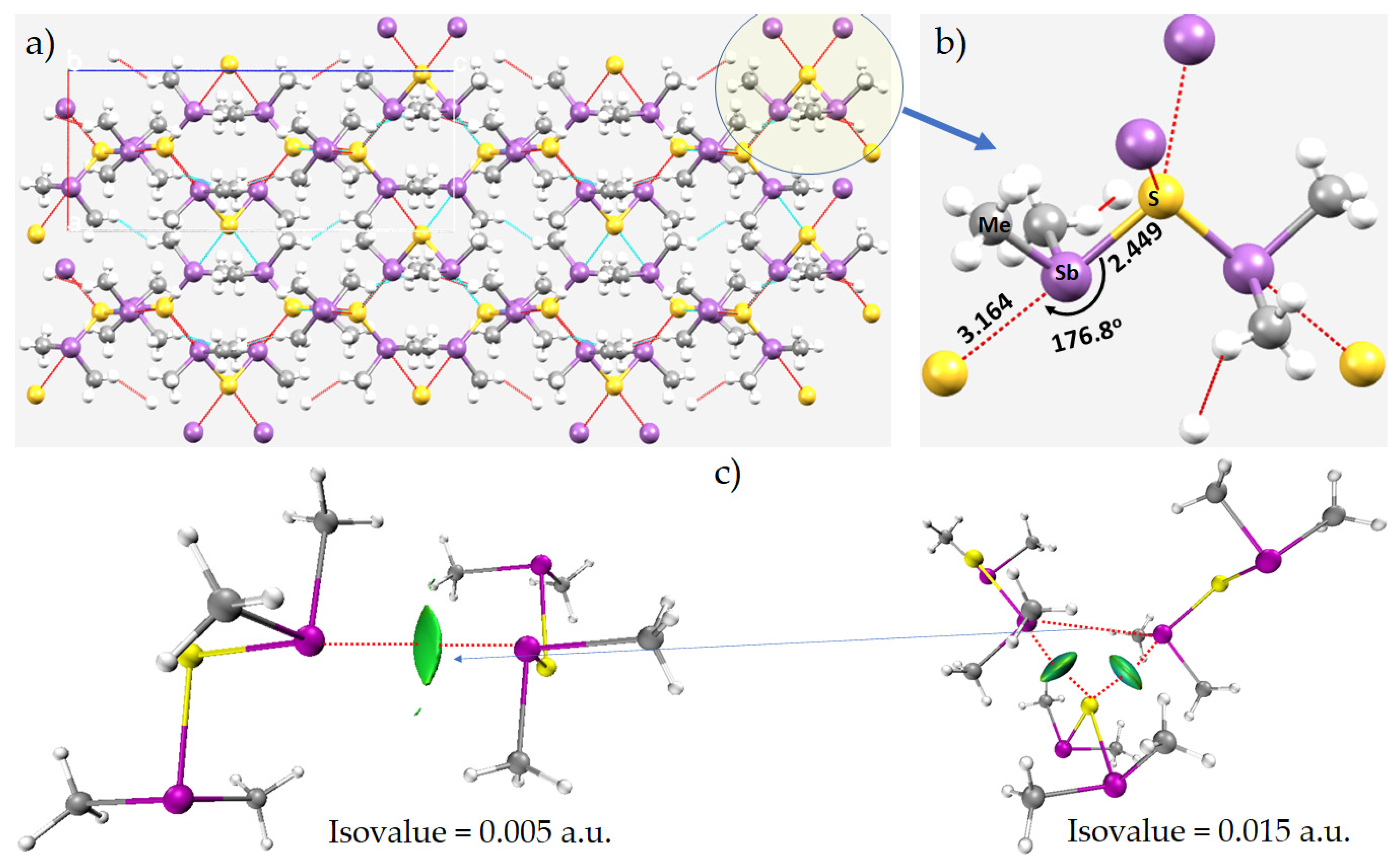
8.5. The Crystal Structures of [(CH3)3Sb–Sb(CH3)2]2[(CH3SbBr3)2], (CH3)2Sb)2O and (CH3)2Sb)2S
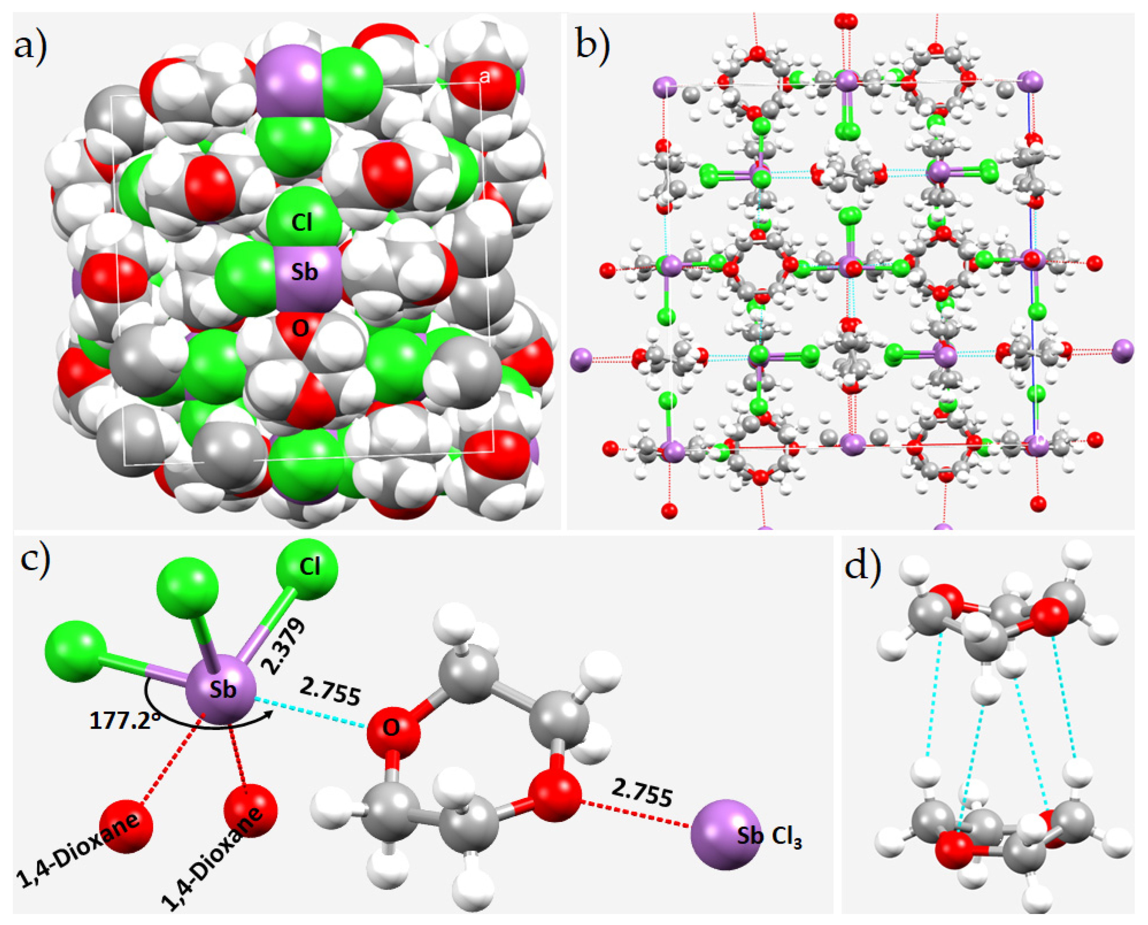
8.6. The Crystal Structure of Catena-(tris(μ2-1,4-dioxane-O,O’)-bis(trichloro-antimony(III))
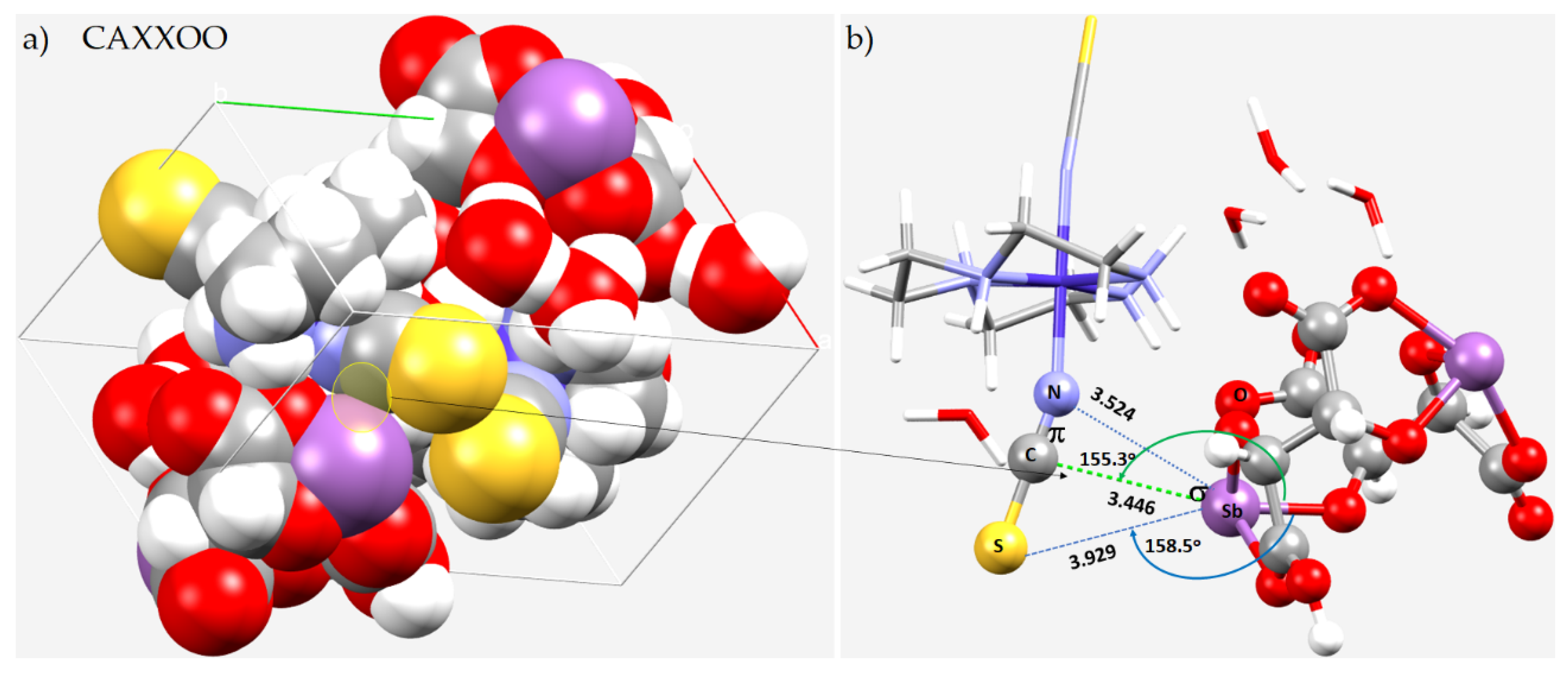
8.7. The Crystal Structure of [Co(trien)(NSC)2][Sb2(tart)(Htart)]
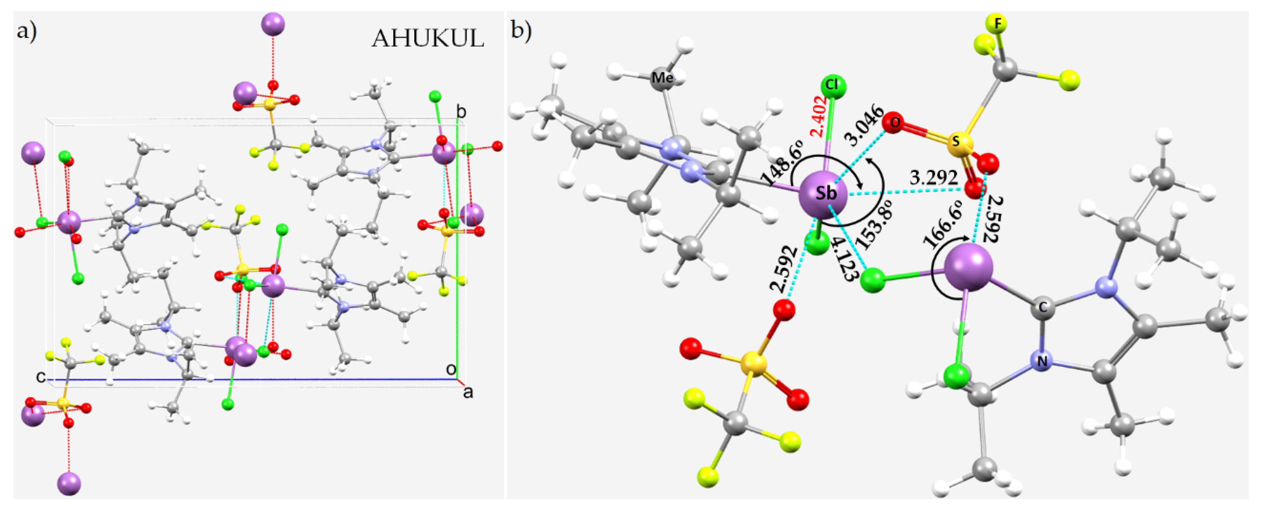
8.8. The Crystal of [SbCl2imR2R’2][OTf]
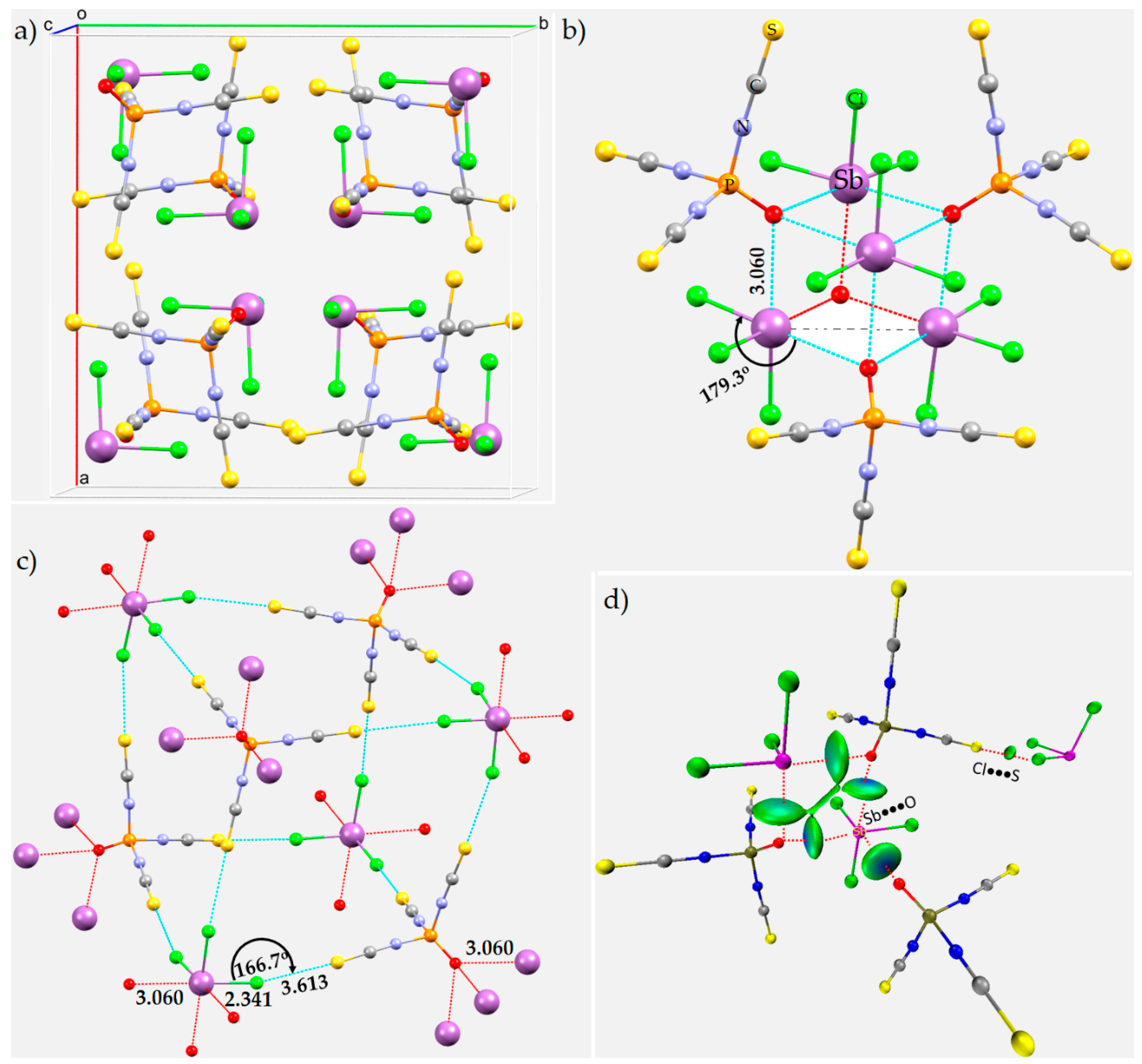
8.9. The Crystal Structures of Phosphoryl Isothiocyanate
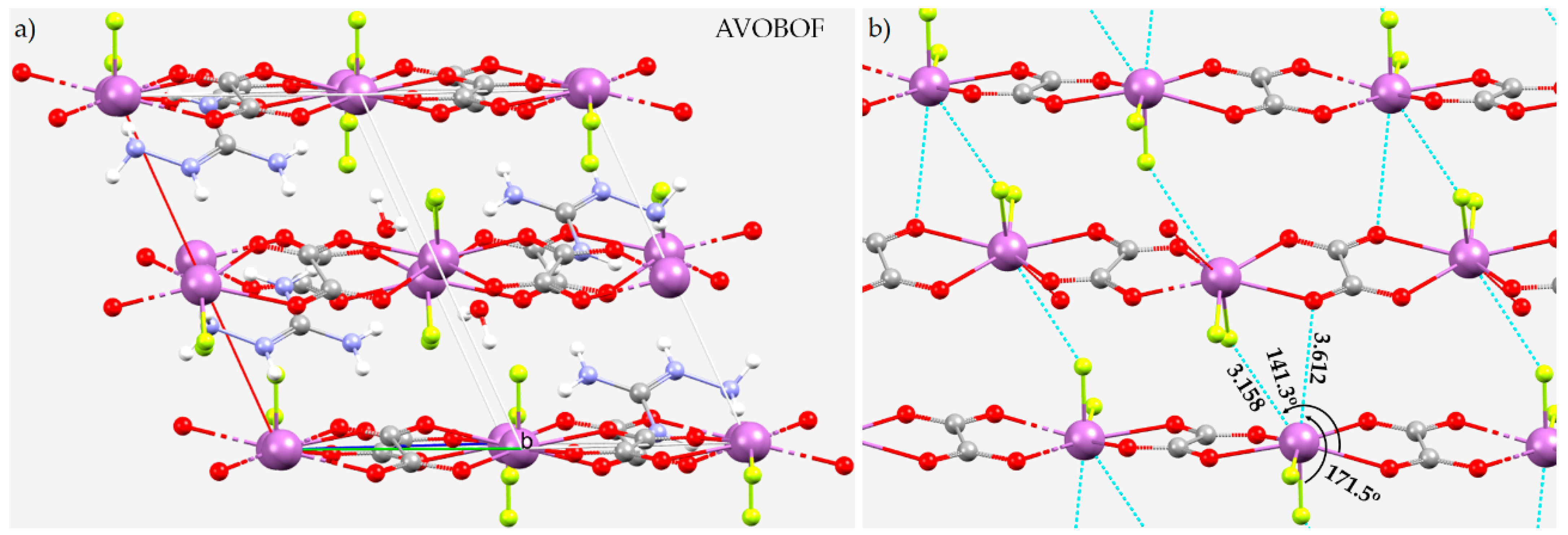
8.10. The Crystal Structure of (CN4H7)SbC2O4F2(H2O)0.5
8.11. Stibium Bonds Formed with Arene Moieties and Other Cyclic and Non-Cyclic Systems
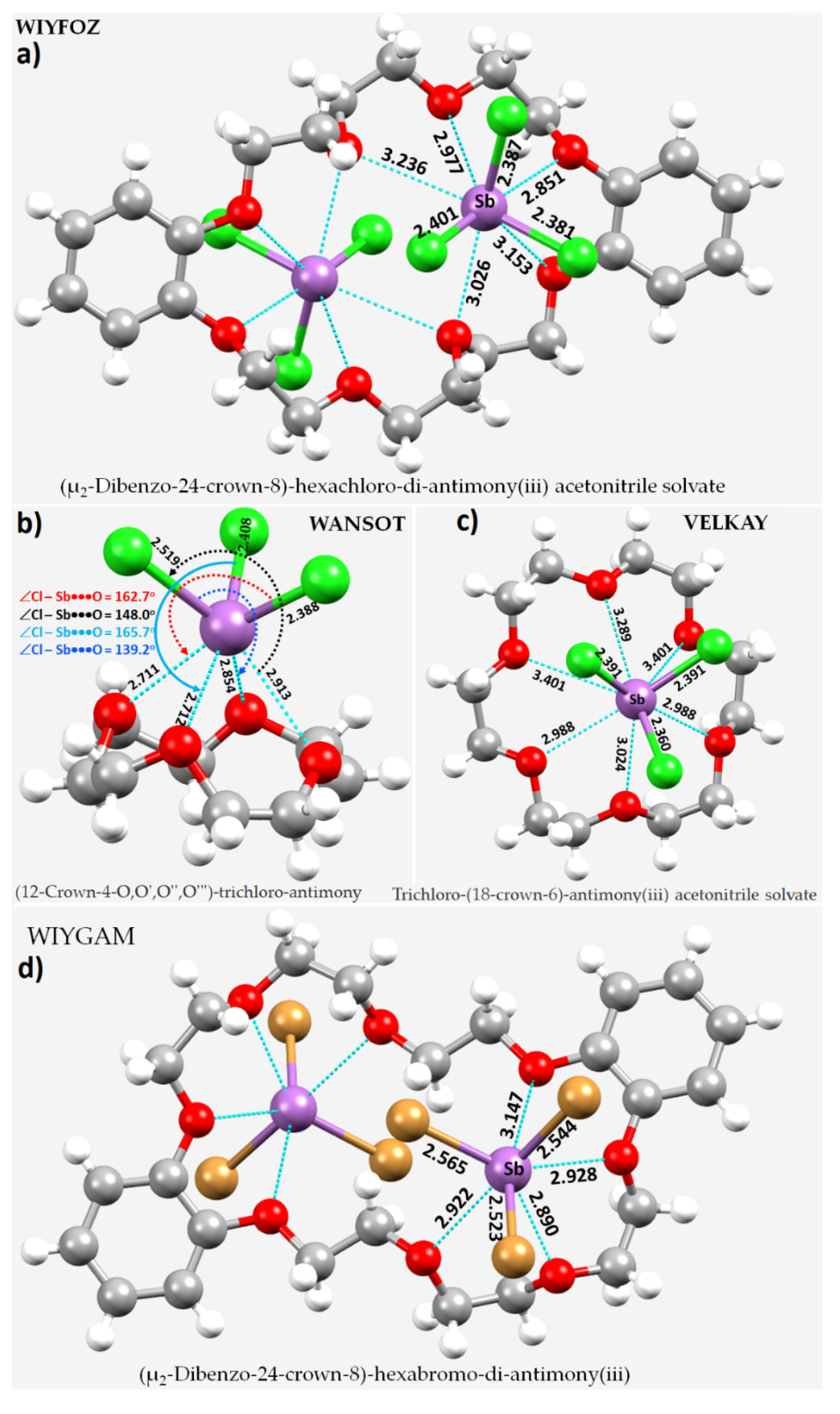
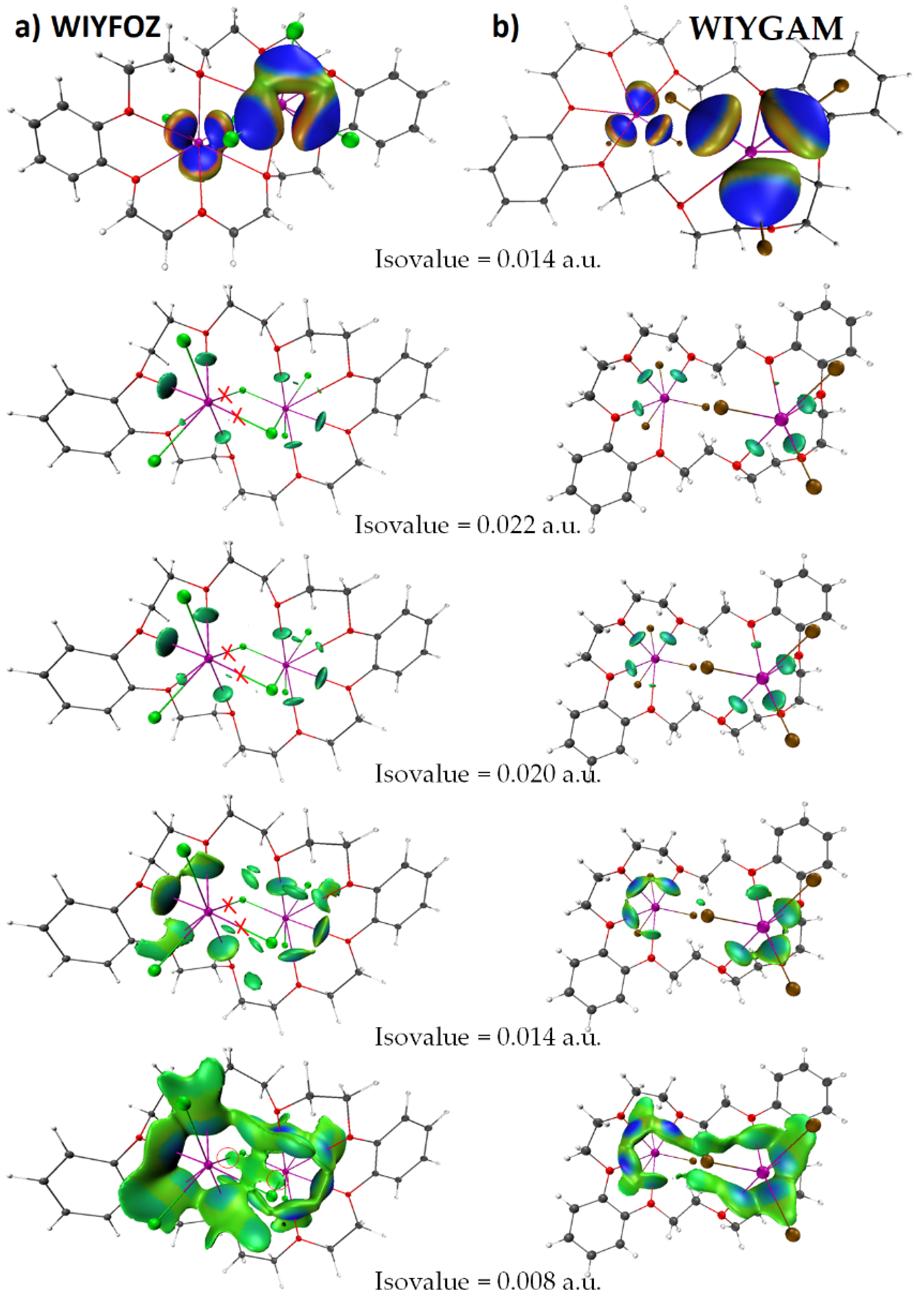
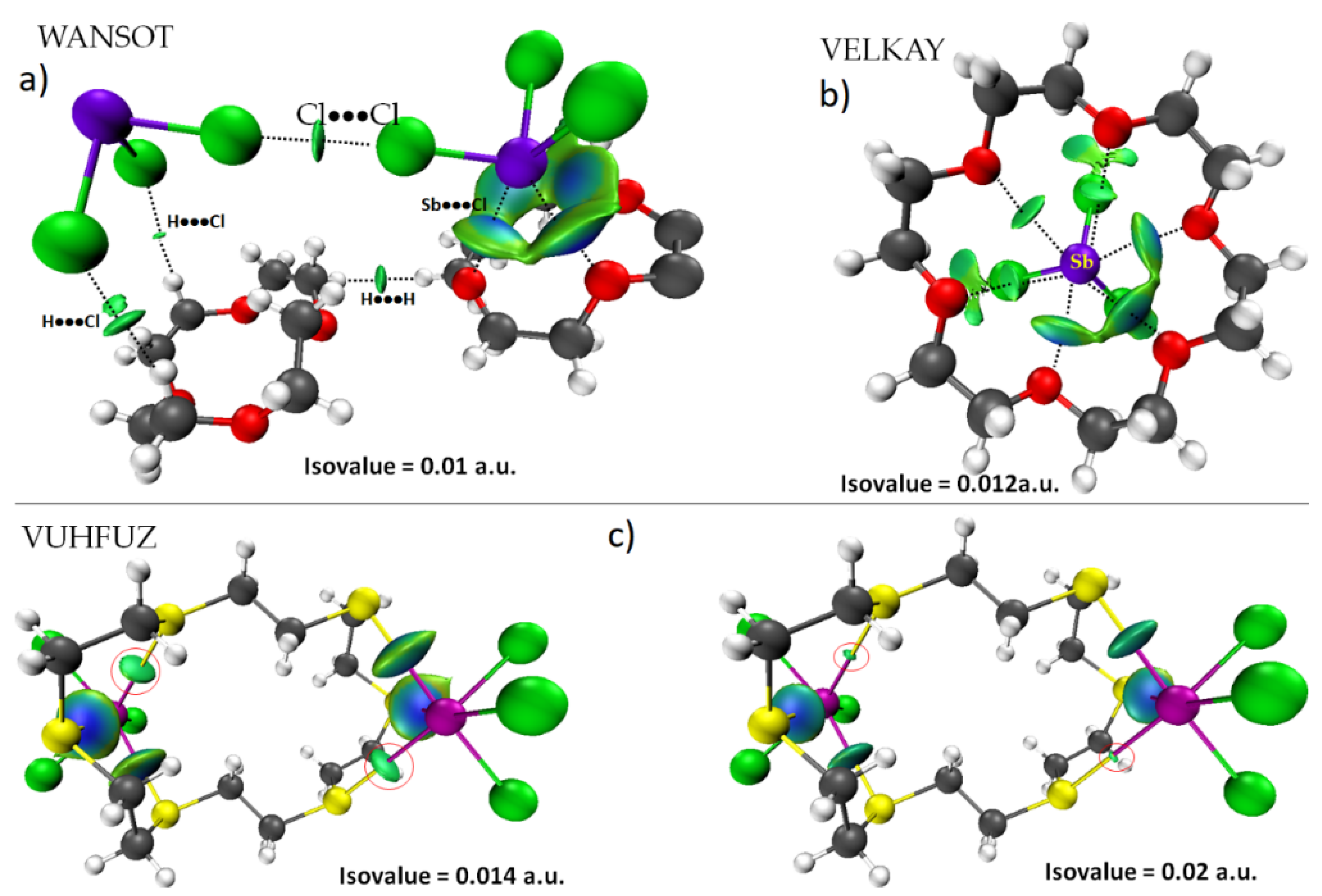
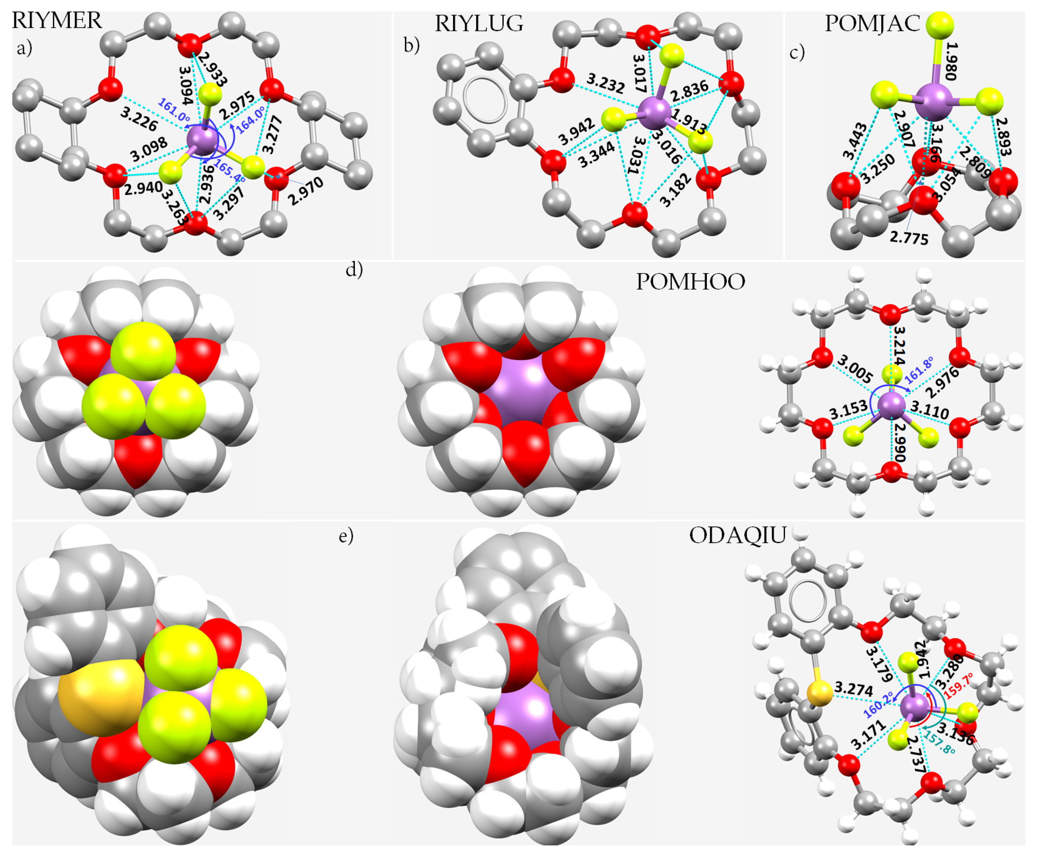
8.12. Crown Ethers as Pnictogen Bond Acceptor Hosts for the Formation of Stibium Bonds
9. Conclusions
Author Contributions
Funding
Institutional Review Board Statement
Informed Consent Statement
Data Availability Statement
Acknowledgments
Conflicts of Interest
References
- Martin, T.W.; Derewenda, Z.S. The name is bond—H bond. Nat. Struct. Mol. Biol. 1999, 6, 403–406. [Google Scholar] [CrossRef] [PubMed]
- Desiraju, G.R. A Bond by Any Other Name. Angew. Chem. Int. Ed. 2011, 50, 52–59. [Google Scholar] [CrossRef] [PubMed]
- Arunan, E. Definitions of a Hydrogen Bond (and References Therein). Available online: https://ipc.iisc.ac.in/~ea/iupac/iupac/Definition_of_HydrogenBond.pdf (accessed on 22 March 2022).
- Werner, A. Ueber Haupt- und Nebenvalenzen und die Constitution der Ammoniumverbindungen. Justus Liebigs Annal. Chem. 1902, 322, 261–296. [Google Scholar] [CrossRef]
- Hantzsch, A. Über die Isomerie-Gleichgewichte des Acetessigesters und die sogen. Isorrhopesis seiner Salze. Chem. Ber. 1910, 43, 3049–3076. [Google Scholar] [CrossRef]
- Pfeiffer, P.; Fischer, P.; Kuntner, J.; Monti, P.; Pros, Z. Zur Theorie der Farblacke, II. Justus Liebigs Annal. Chem. 1913, 398, 137–196. [Google Scholar] [CrossRef] [Green Version]
- Arunan, E.; Desiraju, G.R.; Klein, R.A.; Sadlej, J.; Scheiner, S.; Alkorta, I.; Clary, D.C.; Crabtree, R.H.; Dannenberg, J.J.; Hobza, P.; et al. Definition of the hydrogen bond (IUPAC Recommendations 2011). Pure Appl. Chem. 2011, 83, 1637–1641. [Google Scholar] [CrossRef]
- Hartree, D.R. The Wave Mechanics of an Atom with a Non-Coulomb Central Field. Part II. Some Results and Discussion. Math. Proc. Camb. Phil. Soc. 1928, 24, 111–132. [Google Scholar] [CrossRef]
- Slater, J.C. The Self Consistent Field and the Structure of Atoms. Phys. Rev. 1928, 32, 339–348. [Google Scholar] [CrossRef]
- Slater, J.C. Note on Hartree’s Method. Phys. Rev. 1930, 35, 210–211. [Google Scholar] [CrossRef]
- Fock, V. Näherungsmethode zur Lösung des quantenmechanischen Mehrkörperproblems. Zeit. Physik 1930, 61, 126–148. [Google Scholar] [CrossRef]
- Møller, C.; Plesset, M.S. Note on an Approximation Treatment for Many-Electron Systems. Phys. Rev. 1934, 46, 618–622. [Google Scholar] [CrossRef] [Green Version]
- Hohenberg, P.; Kohn, W. Inhomogeneous Electron Gas. Phys. Rev. 1964, 136, B864–B871. [Google Scholar] [CrossRef] [Green Version]
- Levy, M. Universal variational functionals of electron densities, first-order density matrices, and natural spin-orbitals and solution of the v-representability problem. Proc. Natl. Acad. Sci. USA 1979, 76, 6062–6065. [Google Scholar] [CrossRef] [PubMed] [Green Version]
- Hanaor, D.A.H.; Assadi, M.H.N.; Li, S.; Yu, A.; Sorrell, C.C. Ab initio study of phase stability in doped TiO2. Comput. Mech. 2012, 50, 185–194. [Google Scholar] [CrossRef] [Green Version]
- Desiraju, G.R.; Shing Ho, P.; Kloo, L.; Legon, A.C.; Marquardt, R.; Metrangolo, P.; Politzer, P.; Resnati, G.; Rissanen, K. Definition of the halogen bond (IUPAC Recommendations 2013). Pure Appl. Chem. 2013, 85, 1711–1713. [Google Scholar] [CrossRef]
- Aakeroy, C.B.; Bryce, D.L.; Desiraju, R.G.; Frontera, A.; Legon, A.C.; Nicotra, F.; Rissanen, K.; Scheiner, S.; Terraneo, G.; Metrangolo, P.; et al. Definition of the chalcogen bond (IUPAC Recommendations 2019). Pure Appl. Chem. 2019, 91, 1889–1892. [Google Scholar] [CrossRef]
- Thirumoorthi, R.; Chivers, T.; Vargas-Baca, I. S,C,S-Pnictogen bonding in pincer complexes of the methanediide [C(Ph2PS)2]2−. Dalton Trans. 2011, 40, 8086–8088. [Google Scholar] [CrossRef] [PubMed]
- Legon, A.C. Tetrel, pnictogen and chalcogen bonds identified in the gas phase before they had names: A systematic look at non-covalent interactions. Phys. Chem. Chem. Phys. 2017, 19, 14884–14896. [Google Scholar] [CrossRef] [PubMed]
- Cavallo, G.; Metrangolo, P.; Milani, R.; Pilati, T.; Priimagi, A.; Resnati, G.; Terraneo, G. The halogen bond. Chem. Rev. 2016, 116, 2478–2601. [Google Scholar] [CrossRef] [Green Version]
- Varadwaj, A.; Varadwaj, P.R.; Yamashita, K. Do surfaces of positive electrostatic potential on different halogen derivatives in molecules attract? like attracting like! J. Comput. Chem. 2018, 39, 343–350. [Google Scholar] [CrossRef]
- Varadwaj, P.R.; Varadwaj, A.; Marques, H.M. Halogen Bonding: A Halogen-Centered Noncovalent Interaction Yet to Be Understood. Inorganics 2019, 7, 40. [Google Scholar] [CrossRef] [Green Version]
- Varadwaj, A.; Marques, H.M.; Varadwaj, P.R. Is the Fluorine in Molecules Dispersive? Is Molecular Electrostatic Potential a Valid Property to Explore Fluorine-Centered Non-Covalent Interactions? Molecules 2019, 24, 379. [Google Scholar] [CrossRef] [Green Version]
- Mahmudov, K.T.; Kopylovich, M.N.; Guedes da Silva, M.F.C.; Pombeiro, A.J.L. Chalcogen bonding in synthesis, catalysis and design of materials. Dalton Trans. 2017, 46, 10121–10138. [Google Scholar] [CrossRef] [Green Version]
- Pascoe, D.J.; Ling, K.B.; Cockroft, S.L. The Origin of Chalcogen-Bonding Interactions. J. Am. Chem. Soc. 2017, 139, 15160–15167. [Google Scholar] [CrossRef] [Green Version]
- Varadwaj, P.R.; Varadwaj, A.; Marques, H.M.; MacDougall, P.J. The chalcogen bond: Can it be formed by oxygen? Phys. Chem. Chem. Phys. 2019, 21, 19969–19986. [Google Scholar] [CrossRef]
- Varadwaj, P.R. Does Oxygen Feature Chalcogen Bonding? Molecules 2019, 24, 3166. [Google Scholar] [CrossRef] [Green Version]
- Varadwaj, P.R.; Varadwaj, A.; Marques, H.M.; Yamashita, K. Chalcogen Bonding in the Molecular Dimers of WCh2 (Ch = S, Se, Te): On the Basic Understanding of the Local Interfacial and Interlayer Bonding Environment in 2D Layered Tungsten Dichalcogenides. Int. J. Mol. Sci. 2022, 23, 1263. [Google Scholar] [CrossRef]
- Varadwaj, P.R.; Marques, H.M.; Varadwaj, A.; Yamashita, K. Chalcogen···Chalcogen Bonding in Molybdenum Disulfide, Molybdenum Diselenide and Molybdenum Ditelluride Dimers as Prototypes for a Basic Understanding of the Local Interfacial Chemical Bonding Environment in 2D Layered Transition Metal Dichalcogenides. Inorganics 2022, 10, 11. [Google Scholar] [CrossRef]
- Varadwaj, P.R.; Varadwaj, A.; Marques, H.M. Very strong chalcogen bonding: Is oxygen in molecule capable of forming it? A First Princiles Perspective. Authorea 2020. [Google Scholar] [CrossRef]
- Zahn, S.; Frank, R.; Hey-Hawkins, E.; Kirchner, B. Pnicogen Bonds: A New Molecular Linker? Chem. Eur. J. 2011, 17, 6034–6038. [Google Scholar] [CrossRef]
- Scheiner, S. A new noncovalent force: Comparison of P···N interaction with hydrogen and halogen bonds. J. Chem. Phys. 2011, 134, 094315. [Google Scholar] [CrossRef] [Green Version]
- Del Bene, J.E.; Alkorta, I.; Sanchez-Sanz, G.; Elguero, J. 31P–31P spin–spin coupling constants for pnicogen homodimers. Chem. Phys. Lett. 2011, 512, 184–187. [Google Scholar] [CrossRef]
- Gini, A.; Paraja, M.; Galmés, B.; Besnard, C.; Poblador-Bahamonde, A.I.; Sakai, N.; Frontera, A.; Matile, S. Pnictogen-bonding catalysis: Brevetoxin-type polyether cyclizations. Chem. Sci. 2020, 11, 7086–7091. [Google Scholar] [CrossRef]
- Humeniuk, H.V.; Gini, A.; Hao, X.; Coelho, F.; Sakai, N.; Matile, S. Pnictogen-Bonding Catalysis and Transport Combined: Polyether Transporters Made In Situ. JACS Au 2021, 1, 1588–1593. [Google Scholar] [CrossRef]
- Paraja, M.; Gini, A.; Sakai, N.; Matile, S. Pnictogen-Bonding Catalysis: An Interactive Tool to Uncover Unorthodox Mechanisms in Polyether Cascade Cyclizations. Chem. Eur. J. 2020, 26, 15471–15476. [Google Scholar] [CrossRef]
- Benz, S.; Poblador-Bahamonde, A.I.; Low-Ders, N.; Matile, S. Catalysis with Pnictogen, Chalcogen, and Halogen Bonds. Angew. Chem. Int. Ed. 2018, 57, 5408–5412. [Google Scholar] [CrossRef]
- Taylor, M.S. Anion recognition based on halogen, chalcogen, pnictogen and tetrel bonding. Coord. Chem. Rev. 2020, 413, 213270. [Google Scholar] [CrossRef]
- Qiu, J.; Song, B.; Li, X.; Cozzolino, A.F. Solution and gas phase evidence of anion binding through the secondary bonding interactions of a bidentate bis-antimony(iii) anion receptor. Phys. Chem. Chem. Phys. 2018, 20, 46–50. [Google Scholar] [CrossRef]
- Lee, L.M.; Tsemperouli, M.; Poblador-Bahamonde, A.I.; Benz, S.; Sakai, N.; Sugihara, K.; Matile, S. Anion Transport with Pnictogen Bonds in Direct Comparison with Chalcogen and Halogen Bonds. J. Am. Chem. Soc. 2019, 141, 810–814. [Google Scholar] [CrossRef]
- Moaven, S.; Andrews, M.C.; Polaske, T.J.; Karl, B.M.; Unruh, D.K.; Bosch, E.; Bowling, N.P.; Cozzolino, A.F. Triple-Pnictogen Bonding as a Tool for Supramolecular Assembly. Inorg. Chem. 2019, 58, 16227–16235. [Google Scholar] [CrossRef]
- Mahmudov, K.T.; Gurbanov, A.V.; Aliyeva, V.A.; Resnati, G.; Pombeiro, A.J.L. Pnictogen bonding in coordination chemistry. Coord. Chem. Rev. 2020, 418, 213381. [Google Scholar] [CrossRef]
- Mahmudov, K.T.; Huseynov, F.E.; Aliyeva, V.A.; Guedes da Silva, M.F.C.; Pombeiro, A.J.L. Noncovalent Interactions at Lanthanide Complexes. Chem. Eur. J. 2021, 27, 14370–14389. [Google Scholar] [CrossRef]
- Liu, C.; Shin, J.; Son, S.; Choe, Y.; Farokhzad, N.; Tang, Z.; Xiao, Y.; Kong, N.; Xie, T.; Kim, J.S.; et al. Pnictogens in medicinal chemistry: Evolution from erstwhile drugs to emerging layered photonic nanomedicine. Chem. Soc. Rev. 2021, 50, 2260–2279. [Google Scholar] [CrossRef]
- Fanfrlík, J.; Hnyk, D. Dihalogen and Pnictogen Bonding in Crystalline Icosahedral Phosphaboranes. Crystals 2018, 8, 390. [Google Scholar] [CrossRef] [Green Version]
- Sobalev, S.; Matveychuk, Y.; Bartashevich, E. Features of the Pnictogen Bonds Formed by Neighboring Nitro Groups in Crystals. Bull. South Ural. State Univ. Chem. 2019, 11, 66–75. [Google Scholar] [CrossRef] [Green Version]
- Frontera, A.; Bauzá, A. On the Importance of σ–Hole Interactions in Crystal Structures. Crystals 2021, 11, 1205. [Google Scholar] [CrossRef]
- Shukla, R.; Chopra, D. Chalcogen and pnictogen bonds: Insights and relevance. Curr. Sci. 2021, 120, 1848–1853. [Google Scholar] [CrossRef]
- Varadwaj, P.R.; Varadwaj, A.; Marques, H.M.; Yamashita, K. The Nitrogen Bond, or the Nitrogen-centered Pnictogen Bond: The Covalently Bound Nitrogen Atom in Molecular Entities and Crystals as a Pnictogen Bond Donor. Compounds 2022, 2, 80–110. [Google Scholar] [CrossRef]
- Varadwaj, P.R.; Varadwaj, A.; Marques, H.M.; Yamashita, K. The Phosphorous Bond, or the Phosphorous-Centered Pnictogen Bond: The Covalently Bound Phosphorous Atom in Molecular Entities and Crystals as a Pnictogen Bond Donor. Molecules 2022, 27, 1487. [Google Scholar] [CrossRef]
- Trubenstein, H.J.; Moaven, S.; Vega, M.; Unruh, D.K.; Cozzolino, A.F. Pnictogen bonding with alkoxide cages: Which pnictogen is best? New J. Chem. 2019, 43, 14305–14312. [Google Scholar] [CrossRef]
- Rodrigues, R.R.; Gabbaï, F.P. Structural Evidence for Pnictogen-Centered Lewis Acidity in Cationic Platinum-Stibine Complexes Featuring Pendent Amino or Ammonium Groups. Molecules 2021, 26, 1985. [Google Scholar] [CrossRef] [PubMed]
- Frontera, A.; Bauza, A. On the Importance of Pnictogen and Chalcogen Bonding Interactions in Supramolecular Catalysis. Int. J. Mol. Sci. 2021, 22, 12550. [Google Scholar] [CrossRef] [PubMed]
- International Chemistryl Structure Database (ICSD). Available online: https://icsd.products.fiz-karlsruhe.de/en (accessed on 25 January 2022).
- Belsky, A.; Hellenbrandt, M.; Karen, V.L.; Luksch, P. New developments in the Inorganic Crystal Structure Database (ICSD): Accessibility in support of materials research and design. Acta Crystallogr. B 2002, 58, 364–369. [Google Scholar] [CrossRef] [PubMed] [Green Version]
- Groom, C.R.; Bruno, I.J.; Lightfoot, M.P.; Ward, S.C. The Cambridge Structural Database. Acta Cryst. 2016, B72, 171–179. [Google Scholar] [CrossRef] [PubMed]
- Yang, Y.; Liu, C.; Cai, M.; Liao, Y.; Ding, Y.; Ma, S.; Liu, X.; Guli, M.; Dai, S.; Nazeeruddin, M.K. Dimension-Controlled Growth of Antimony-Based Perovskite-like Halides for Lead-Free and Semitransparent Photovoltaics. ACS Appl. Mater. Interfaces 2020, 12, 17062–17069. [Google Scholar] [CrossRef]
- Tuohey, H.; Della Gaspera, E.; van Embden, J. Perovskite-Inspired High Stability Organometal Antimony(V) Halide Thin Films by Post-Deposition Bromination. ACS Mater. Lett. 2020, 2, 1203–1210. [Google Scholar] [CrossRef]
- Jin, Z.; Zhang, Z.; Xiu, J.; Song, H.; Gatti, T.; He, Z. A critical review on bismuth and antimony halide based perovskites and their derivatives for photovoltaic applications: Recent advances and challenges. J. Mater. Chem. A 2020, 8, 16166–16188. [Google Scholar] [CrossRef]
- Guo, P.; Sarangan, A.M.; Agha, I. A Review of Germanium-Antimony-Telluride Phase Change Materials for Non-Volatile Memories and Optical Modulators. Appl. Sci. 2019, 9, 530. [Google Scholar] [CrossRef] [Green Version]
- Kao, K.-F.; Chang, C.-C.; Chen, F.T.; Tsai, M.-J.; Chin, T.-S. Antimony alloys for phase-change memory with high thermal stability. Scr. Mater. 2010, 63, 855–858. [Google Scholar] [CrossRef]
- Turkevych, I.; Kazaoui, S.; Ito, E.; Urano, T.; Yamada, K.; Tomiyasu, H.; Yamagishi, H.; Kondo, M.; Aramaki, S. Photovoltaic Rudorffites: Lead-Free Silver Bismuth Halides Alternative to Hybrid Lead Halide Perovskites. ChemSusChem 2017, 10, 3754–3759. [Google Scholar] [CrossRef]
- Jia, X.; Ding, L. A low-temperature solution-processed copper antimony iodide rudorffite for solar cells. Sci. China Mater. 2019, 62, 54–58. [Google Scholar] [CrossRef] [Green Version]
- Lv, K.; Qi, S.; Liu, G.; Lou, Y.; Chen, J.; Zhao, Y. Lead-free silver-antimony halide double perovskite quantum dots with superior blue photoluminescence. Chem. Commun. 2019, 55, 14741–14744. [Google Scholar] [CrossRef] [PubMed]
- Vargas, B.; Ramos, E.; Pérez-Gutiérrez, E.; Alonso, J.C.; Solis-Ibarra, D. A Direct Bandgap Copper–Antimony Halide Perovskite. J. Am. Chem. Soc. 2017, 139, 9116–9119. [Google Scholar] [CrossRef] [PubMed]
- Politzer, P.; Murray, J.S. The use and misuse of van der Waals radii. Struct. Chem. 2021, 32, 623–629. [Google Scholar] [CrossRef]
- Dance, I. Distance criteria for crystal packing analysis of supramolecular motifs. New J. Chem. 2003, 27, 22–27. [Google Scholar] [CrossRef]
- Alvarez, S. A cartography of the van der Waals territories. Dalton Trans. 2013, 42, 8617–8636. [Google Scholar] [CrossRef] [PubMed] [Green Version]
- Bondi, A. Van Der Waals Volumes and Radii. J. Phys. Chem 1964, 68, 441–451. [Google Scholar] [CrossRef]
- Batsanov, S.S. Van der Waals Radii of Elements. Inorg. Mater. 2001, 37, 871–885. [Google Scholar] [CrossRef]
- Mantina, M.; Chamberlin, A.C.; Valero, R.; Cramer, C.J.; Truhlar, D.G. Consistent van der Waals Radii for the Whole Main Group. J. Phys. Chem. A 2009, 113, 5806–5812. [Google Scholar] [CrossRef] [PubMed] [Green Version]
- Ibrahim, M.A.A.; Moussa, N.A.M. Unconventional Type III Halogen···Halogen Interactions: A Quantum Mechanical Elucidation of σ-Hole···σ-Hole and Di-σ-Hole Interactions. ACS Omega 2020, 5, 21824–21835. [Google Scholar] [CrossRef] [PubMed]
- Clark, T.; Hennemann, M.; Murray, J.S.; Politzer, P. Halogen bonding: The σ-hole. J. Mol. Model. 2007, 13, 291–296. [Google Scholar] [CrossRef] [PubMed]
- Murray, J.S.; Lane, P.; Politzer, P. Expansion of the σ-hole concept. J. Mol. Model. 2009, 15, 723–729. [Google Scholar] [CrossRef]
- Varadwaj, A.; Varadwaj, P.R.; Jin, B.-Y. Can an entirely negative fluorine in a molecule, viz. perfluorobenzene, interact attractively with the entirely negative site(s) on another molecule(s)? Like liking like! RSC Adv. 2016, 6, 19098–19110. [Google Scholar] [CrossRef]
- Varadwaj, A.; Varadwaj, P.R.; Jin, B.-Y. Fluorines in tetrafluoromethane as halogen bond donors: Revisiting address the nature of the fluorine’s σ-hole. Int. J. Quantum Chem. 2015, 115, 453–470. [Google Scholar] [CrossRef]
- Varadwaj, P.R.; Varadwaj, A.; Marques, H.M. Does Chlorine in CH3Cl Behave as a Genuine Halogen Bond Donor? Crystals 2020, 10, 146. [Google Scholar] [CrossRef] [Green Version]
- Ibrahim, M.A.A.; Hasb, A.A.M. Polarization plays the key role in halogen bonding: A point-of-charge-based quantum mechanical study. Theor. Chem. Acc. 2018, 138, 2. [Google Scholar] [CrossRef]
- Varadwaj, P.R.; Varadwaj, A.; Jin, B.-Y. Significant evidence of C···O and C···C long-range contacts in several heterodimeric complexes of CO with CH3-X, should one refer to them as carbon and dicarbon bonds! Phys. Chem. Chem. Phys. 2014, 16, 17238–17252. [Google Scholar] [CrossRef] [PubMed]
- Frisch, M.J.; Trucks, G.W.; Schlegel, H.B.; Scuseria, G.E.; Robb, M.A.; Cheeseman, J.R.; Scalmani, G.; Barone, V.; Mennucci, B.; Petersson, G.A.; et al. Gaussian 09, Rev. C.01; Gaussian, Inc.: Wallinford, CT, USA, 2016. [Google Scholar]
- Chai, J.-D.; Head-Gordon, M. Long-range corrected hybrid density functionals with damped atom–atom dispersion corrections. Phys. Chem. Chem. Phys. 2008, 10, 6615–6620. [Google Scholar] [CrossRef] [PubMed] [Green Version]
- Frisch, M.J.; Head-Gordon, M.; Pople, J.A. A direct MP2 gradient method. Chem. Phys. Lett. 1990, 166, 275–280. [Google Scholar] [CrossRef]
- Pritchard, B.P.; Altarawy, D.; Didier, B.; Gibson, T.D.; Windus, T.L. New Basis Set Exchange: An Open, Up-to-Date Resource for the Molecular Sciences Community. J. Chem. Inf. Model. 2019, 59, 4814–4820. [Google Scholar] [CrossRef] [PubMed]
- Schuchardt, K.L.; Didier, B.T.; Elsethagen, T.; Sun, L.; Gurumoorthi, V.; Chase, J.; Li, J.; Windus, T.L. Basis Set Exchange: A Community Database for Computational Sciences. J. Chem. Inf. Model. 2007, 47, 1045–1052. [Google Scholar] [CrossRef] [PubMed] [Green Version]
- Murray, J.S.; Politzer, P. The electrostatic potential: An overview. WIREs Comput. Mol. Sci. 2011, 1, 153–163. [Google Scholar] [CrossRef]
- Keith, T.A. AIMAll (V. 19.10.12); TK Gristmill Software: Overland Park, KS, USA, 2019; Available online: https://aim.tkgristmill.com (accessed on 22 March 2022).
- Lu, T.; Chen, F. Multiwfn: A multifunctional wavefunction analyzer. J. Comp. Chem. 2012, 33, 580–592. [Google Scholar] [CrossRef] [PubMed]
- Macrae, C.F.; Bruno, I.J.; Chisholm, J.A.; Edgington, P.R.; McCabe, P.; Pidcock, E.; Rodriguez-Monge, L.; Taylor, R.; van de Streek, J.; Wood, P.A. Mercury 4.0: From visualization to analysis, design and prediction. J. Appl. Cryst. 2008, 41, 466–470. [Google Scholar] [CrossRef]
- Dennington, R.; Keith, T.; Millam, J. GaussView, V. 5, 5.0.9; Semichem, Inc.: Shawnee Mission, KS, USA, 2009. [Google Scholar]
- Humphrey, W.; Dalke, A.; Schulten, K. VMD—Visual Molecular Dynamics. J. Mol. Graph. 1996, 14, 33–38. [Google Scholar] [CrossRef]
- Varadwaj, A.; Varadwaj, P.R.; Marques, H.M.; Yamashita, K. Revealing Factors Influencing the Fluorine-Centered Non-Covalent Interactions in Some Fluorine-substituted Molecular Complexes: Insights from First-Principles Studies. ChemPhysChem 2018, 19, 1486–1499. [Google Scholar] [CrossRef] [PubMed]
- Murray, J.S.; Politzer, P. Molecular Surfaces, van der Waals Radii and Electrostatic Potentials in Relation to Noncovalent Interactions. Croat. Chem. Acta 2009, 82, 267–275. [Google Scholar]
- Varadwaj, P.R.; Varadwaj, A.; Jin, B.-Y. Unusual bonding modes of perfluorobenzene in its polymeric (dimeric, trimeric and tetrameric) forms: Entirely negative fluorine interacting cooperatively with entirely negative fluorine. Phys. Chem. Chem. Phys. 2015, 17, 31624–31645. [Google Scholar] [CrossRef]
- Bader, R.F.W.; Henneker, W.H.; Cade, P.E. Molecular Charge Distributions and Chemical Binding. J. Chem. Phys. 1967, 46, 3341–3363. [Google Scholar] [CrossRef]
- Bader, R.F.W.; Preston, H.J.T. Determination of the charge distribution of methane by a method of density constraints. Theor. Chim. Acta 1970, 17, 384–395. [Google Scholar] [CrossRef]
- Kahn, S.D.; Pau, C.F.; Hehre, W.J. Models for chemical reactivity: Mapping of intermolecular potentials onto electron density surfaces. Int. J. Quant. Chem. 1988, 34, 575–591. [Google Scholar] [CrossRef]
- Lefebvre, C.; Rubez, G.; Khartabil, H.; Boisson, J.-C.; Contreras-García, J.; Hénon, E. Accurately extracting the signature of intermolecular interactions present in the NCI plot of the reduced density gradient versus electron density. Phys. Chem. Chem. Phys. 2017, 19, 17928–17936. [Google Scholar] [CrossRef] [PubMed]
- Lefebvre, C.; Khartabil, H.; Boisson, J.-C.; Contreras-García, J.; Piquemal, J.-P.; Hénon, E. The Independent Gradient Model: A New Approach for Probing Strong and Weak Interactions in Molecules from Wave Function Calculations. ChemPhysChem 2018, 19, 724–735. [Google Scholar] [CrossRef] [PubMed]
- Pathak, R.K.; Gadre, S.R. Maximal and minimal characteristics of molecular electrostatic potentials. J. Chem. Phys. 1990, 93, 1770–1773. [Google Scholar] [CrossRef]
- Politzer, P.; Truhlar, D.G. (Eds.) Chemical Applications of Atomic and Molecular Electrostatic Potentials; Plenum Press: New York, NY, USA, 1981. [Google Scholar]
- Kumar, V.; Scilabra, P.; Politzer, P.; Terraneo, G.; Daolio, A.; Fernandez-Palacio, F.; Murray, J.S.; Resnati, G. Tetrel and Pnictogen Bonds Complement Hydrogen and Halogen Bonds in Framing the Interactional Landscape of Barbituric Acids. Cryst. Growth Des. 2021, 21, 642–652. [Google Scholar] [CrossRef]
- Gomila, R.M.; Frontera, A. Charge assisted halogen and pnictogen bonds: Insights from the Cambridge Structural Database and DFT calculations. CrystEngComm 2020, 22, 7162–7169. [Google Scholar] [CrossRef]
- Fanfrlík, J.; Zierkiewicz, W.; Švec, P.; Růžičková, Z.; Řezáč, J.; Michalczyk, M.; Růžička, A.; Michalska, D.; Hobza, P. Pnictogen bonding in pyrazine•PnX5 (Pn = P, As, Sb and X = F, Cl, Br) complexes. J. Mol. Model. 2017, 23, 328. [Google Scholar] [CrossRef]
- Lindquist-Kleissler, B.; Wenger, J.S.; Johnstone, T.C. Analysis of Oxygen–Pnictogen Bonding with Full Bond Path Topological Analysis of the Electron Density. Inorg. Chem. 2021, 60, 1846–1856. [Google Scholar] [CrossRef]
- Mokrai, R.; Barrett, J.; Apperley, D.C.; Batsanov, A.S.; Benkő, Z.; Heift, D. Weak Pnictogen Bond with Bismuth: Experimental Evidence Based on Bi−P Through-Space Coupling. Chem. Eur. J. 2019, 25, 4017–4024. [Google Scholar] [CrossRef] [Green Version]
- Politzer, P.; Murray, J.S.; Janjić, G.V.; Zarić, S.D. σ-Hole interactions of covalently-bonded nitrogen, phosphorus and arsenic: A survey of crystal structures. Crystals 2014, 4, 12–31. [Google Scholar] [CrossRef] [Green Version]
- de Azevedo Santos, L.; van der Lubbe, S.C.C.; Hamlin, T.A.; Ramalho, T.C.; Matthias Bickelhaupt, F. A Quantitative Molecular Orbital Perspective of the Chalcogen Bond. ChemistryOpen 2021, 10, 391–401. [Google Scholar] [CrossRef] [PubMed]
- Williams, D.J.; Vanderveer, D.; Jones, R.L.; Menaldino, D.S. Main group metal halide complexes with sterically hindered thioureas XI. Complexes of antimony(III) and bismuth(III) chlorides with a new bidentate thiourea—1,1′-methylenebis(3-methyl-2H-imidazole-2-thione). Inorg. Chim. Acta 1989, 165, 173–178. [Google Scholar] [CrossRef]
- Willey, G.R.; Lakin, M.T.; Ravindran, M.; Alcock, N.W. Crown thioether complexes of p-block elements: Crystal and molecular structures of SbCl3·9s3 (9s3 = 1,4,7-trithiacyclononane) and 2SbCl3·18S6 (18S6 = 1,4,7,10,13,16-hexathiacyclooctadecane). J. Chem. Soc. Chem. Commun. 1991, 271–272. [Google Scholar] [CrossRef]
- Probst, T.; Steigelmann, O.; Riede, J.; Schmidbaur, H. Arsen(III)-, Antimon(III)- und Bismuth(III)-halogenid-Komplexe des [2.2.2]Paracyclophans: Vom lockeren van-der-Waals-Addukt zu stark gerichteten π-Komplexen mit zwei- und dreifacher externer η6-Koordination. Chem. Bericht. 2006, 124, 1089–1093. [Google Scholar] [CrossRef]
- Lipka, A.; Mootz, D. Die kristallstruktur des 2;1-Adduktes zwischen Antimontrichlorid und Diphenyl, 2SbCl3·(C6H5)2. Zeit. Anorg. Allg. Chem. 1978, 440, 217–223. [Google Scholar] [CrossRef]
- Schmidbaur, H.; Nowak, R.; Huber, B.; Mueller, G. Hexaethylbenzene-trichloroantimony: A Menshutkin complex with a centroid antimony-arene coordination. Organometallics 1987, 6, 2266–2267. [Google Scholar] [CrossRef]
- Rogers, R.D. CCDC 1588517: Experimental Crystal Structure Determination. Available online: https://0-doi-org.brum.beds.ac.uk/10.5517/ccdc.csd.cc1q9zhh (accessed on 22 March 2022).
- Rogers, R.D. CCDC 1588527: Experimental Crystal Structure Determination. Available online: https://0-doi-org.brum.beds.ac.uk/10.5517/ccdc.csd.cc1q9zt (accessed on 22 March 2022).
- Mootz, D.; Händler, V. Crystal Structure of the Menshutkin Complex Benzene · 2SbCl3. Z. Anorg. Allg. Chem. 1986, 533, 23–29. [Google Scholar] [CrossRef]
- Mootz, D.; Händler, V. Die Komplexe Pyren 2SbCl3 und Phenanthren—2 SbBr3 Phasenverhalten, Präparation und Kristallstrukturen. Zeit. Anorg. Allg. Chem. 1985, 521, 122–134. [Google Scholar] [CrossRef]
- Ferrari, M.B.; Cramarossa, M.R.; Iarossi, D.; Pelosi, G. Larger Cyclophanes: Synthesis and Structural Characterization of [2.2.2.2]Paracyclophane Compounds with SbBr3 and BiBr3. Inorg. Chem. 1998, 37, 5681–5685. [Google Scholar] [CrossRef]
- Lo, R.; Švec, P.; Růžičková, Z.; Růžička, A.; Hobza, P. On the nature of the stabilisation of the E⋯π pnicogen bond in the SbCl3⋯toluene complex. Chem. Commun. 2016, 52, 3500–3503. [Google Scholar] [CrossRef] [Green Version]
- Burford, N.; Clyburne, J.A.C.; Wiles, J.A.; Cameron, T.S.; Robertson, K.N. Tethered Diarenes as Four-Site Donors to SbCl3. Organometallics 1996, 15, 361–364. [Google Scholar] [CrossRef]
- Konaka, S.; Kimura, M. The Molecular Structure of Antimony Trichloride Determined by Gas-electron Diffraction. Bull. Chem. Soc. Japan 1973, 46, 404–407. [Google Scholar] [CrossRef] [Green Version]
- Kisliuk, P.; Townes, C.H. Molecular Microwave Spectra Tables; Circular 518; National Bureau of Standards: Washington, DC, USA, 1952; Volume 518. [Google Scholar]
- Ballard, J.G.; Birchall, T.; Milne, J.B.; Moffett, W.D. 121Sb Mössbauer Spectroscopy: Stereochemical Activity of the 5s Electrons in some Sb(III) Halide Complexes. Can. J. Chem. 1974, 52, 2375–2379. [Google Scholar] [CrossRef]
- Ballard, J.C. Spectroscopic Studies of Antimony III and V Halide Complexes. PhD Thesis, McMaster University, Hamilton, ON, Canada, 1977. [Google Scholar]
- Serezhkin, V.N.; Buslaev, Y.A. Stereochemical Effect of Lone Pair Electrons in Antimony Fluorides. Russ. J. Inorg. Chem. 1997, 42, 1064–1071. [Google Scholar]
- Gibb, T.C.; Greatrex, R.; Greenwood, N.N.; Sarma, A.C. Mössbauer spectra of some tellurium complexes. J. Chem. Soc. A 1970, 212–217. [Google Scholar] [CrossRef]
- Capel, V.L.; Dillon, K.B.; Goeta, A.E.; Howard, J.A.K.; Monks, P.K.; Probert, M.R.; Shepherd, H.J.; Zorina, N.V. Stereochemically inactive lone pairs in phosphorus(III) compounds: The characterisation of some derivatives with the 2,5-(CF3)2C6H3 (Ar) substituent and their complexation behaviour towards Pt(II) species. Dalton Trans. 2011, 40, 1808–1816. [Google Scholar] [CrossRef]
- Breunig, H.J.; Ebert, K.H.; Gülec, S.; Dräger, M.; Sowerby, D.B.; Begley, M.J.; Behrens, U. Strukturen von [Me4Sb]2[MeSbI4]MeSbI2, und [Me4Sb]I. Darstellung von Me3Sb·MeSbI2 und farbwechsel bei Me4Sb2·Me2SbBr. J. Organomet. Chem. 1992, 427, 39–48. [Google Scholar] [CrossRef]
- Bjorvatten, T.; Hassel, O.; Lindheim, A. Crystal Structure of the Addition Compound SbI3:3S8. Acta Chem. Scand. 1963, 689–702. [Google Scholar] [CrossRef]
- Müller, U.; Mohammed, A.T. Die Kristallstruktur und das Raman-Spektrum von SbCl3 S8. Z. Anorg. Allg. Chem. 1983, 506, 110–114. [Google Scholar] [CrossRef]
- Persson, K. The Materials Project. Materials Data on SbS8Cl3 by Materials Project. Report No. mp-28064. Available online: https://www.osti.gov/biblio/1202185 (accessed on 22 March 2022).
- Edwards, A.J. Fluoride crystal structures. Part XIV. Antimony trifluoride: A redetermination. J. Chem. Soc. A 1970, 2751–2753. [Google Scholar] [CrossRef]
- Zhang, G.; Liu, T.; Zhu, T.; Qin, J.; Wu, Y.; Chen, C. SbF3: A new second-order nonlinear optical material. Opt. Mater. 2008, 31, 110–113. [Google Scholar] [CrossRef]
- Kang, L.; Ramo, D.M.; Lin, Z.; Bristowe, P.D.; Qin, J.; Chen, C. First principles selection and design of mid-IR nonlinear optical halide crystals. J. Mater. Chem. C 2013, 1, 7363–7370. [Google Scholar] [CrossRef]
- Lipka, A. An X-ray structure redetermination of antimony trichloride. Acta Cryst. B 1979, 35, 3020–3022. [Google Scholar] [CrossRef]
- Lindqvist, I.; Niggli, A. The crystal structure of antimony trichloride. J. Inorg. Nucl. Chem. 1956, 2, 345–347. [Google Scholar] [CrossRef]
- Cushen, D.W.; Hulme, R. 427. The crystal and molecular structure of antimony tribromide: β-antimony tribromide. J. Chem. Soc. 1962, 2218–2222. [Google Scholar] [CrossRef]
- Jain, A.; Ong, S.P.; Hautier, G.; Chen, W.; Richards, W.D.; Dacek, S.; Gunter, D.; Skinner, D.; Ceder, G.; Persson, K. The Materials Project. Materials Data on SbBr3. Report mp-570005. Available online: https://materialsproject.org/materials/mp-570005/ (accessed on 22 March 2022).
- Jain, A.; Ong, S.P.; Hautier, G.; Chen, W.; Richards, W.D.; Dacek, S.; Cholia, S.; Gunter, D.; Skinner, D.; Ceder, G.; et al. The Materials Project. Materials Data on SbCl3. Report mp-22872. Available online: https://materialsproject.org/materials/mp-22872/ (accessed on 22 March 2022).
- Pohl, S.; Saak, W. Zur Polymorphie von Antimontriiodid. Die Kristallstruktur von monoklinem SbI3. Z. Kristall. Cryst. Mater. 1984, 169, 177–184. [Google Scholar] [CrossRef]
- Onodera, T.; Baba, K.; Hitomi, K. Evaluation of Antimony Tri-Iodide Crystals for Radiation Detectors. Sci. Tech. Nucl. Instal. 2018, 2018, 1532742. [Google Scholar] [CrossRef] [Green Version]
- Althaus, H.; Breunig, H.J.; Lork, E. Crystal structure of [Me3Sb–SbMe2]2[(MeSbBr3)2], a trimethylstibine adduct of the dimethylstibenium ion or a stibinostibonium salt? Chem. Commun. 1999, 1971–1972. [Google Scholar] [CrossRef]
- Breunig, H.J.; Lork, E.; Rösler, R.; Becker, G.; Mundt, O.; Schwarz, W. Common Features in the Crystal Structures of the Compounds Bis(dimethylstibanyl)oxane and -sulfane, and the Minerals Valentinite and Stibnite (Grauspießglanz). Z. Anorg. Allg. Chem. 2000, 626, 1595–1607. [Google Scholar] [CrossRef]
- Kellett, C.W.; Kennepohl, P.; Berlinguette, C.P. π covalency in the halogen bond. Nature Commun. 2020, 11, 3310. [Google Scholar] [CrossRef] [PubMed]
- Varadwaj, P.R.; Varadwaj, A.; Marques, H.M. DFT-B3LYP, NPA-, and QTAIM-based study of the physical properties of [M(II)(H2O)2(15-crown-5)](M= Mn, Fe, Co, Ni, Cu, Zn) complexes. J. Phys. Chem. A 2011, 115, 5592–5601. [Google Scholar] [CrossRef]
- Varadwaj, P.R.; Varadwaj, A.; Peslherbe, G.H.; Marques, H.M. Conformational Analysis of 18-Azacrown-6 and Its Bonding with Late First Transition Series Divalent Metals: Insight from DFT Combined with NPA and QTAIM Analyses. J. Phys. Chem. A 2011, 115, 13180–13190. [Google Scholar] [CrossRef] [PubMed]
- Rheingold, A.L. BEKHUV01: Catena-[tris(μ-1,4-dioxane)-hexachloro-di-antimony(III)]. Deposition No. 735005. Available online: https://www.ccdc.cam.ac.uk (accessed on 20 December 2021).
- Zang, X.-S.; Chen, Y.-R.; Luan, S.-R.; Zhong, G.-Q.; Guo, Y.-C. Synthesis and Crystal Structure of the Complex of Antimony Trichloride and Dioxane. Wuji Huaxue Xuebao (Chin. J. Inorg. Chem.) 2001, 17, 901–904. [Google Scholar]
- Yoshihiko, K.; Masahiro, K.; Shunji, U.; Hayami, Y. Structural Study of Optical Resolution. XII. The Crystal and Molecular Structure of (−)589-trans-SS-Bis(isothiocyanato)(triethylenetetramine)cobalt(III) μ-(+)-Tartrato(4−)-μ-(+)-hydrogentartrato(3−)diantimonate(III) Tetrahydrate. Bull. Chem. Soc. Jpn. 1983, 56, 2742–2747. [Google Scholar] [CrossRef] [Green Version]
- Henne, F.D.; Dickschat, A.T.; Hennersdorf, F.; Feldmann, K.O.; Weigand, J.J. Synthesis of Selected Cationic Pnictanes [LnPnX3–n]n+ (L = Imidazolium-2-yl; Pn = P, As; n = 1–3) and Replacement Reactions with Pseudohalogens. Inorg. Chem. 2015, 54, 6849–6861. [Google Scholar] [CrossRef] [PubMed]
- Sienkiewicz, A.V.; Kapshuk, A.A. The Crystal Structure of the Tetrameric Adduct of Antimony Trichloride and Phosphoryl Isothiocyanate, [SbCl3.OP(NCS)3]4. Zeit. Naturforsch. B 1994, 49, 441–444. [Google Scholar] [CrossRef]
- Lindemann, W.; Wögerbauer, R.; Berger, P. Die Kristallstrukturen von SbCl3 (CH2S)3 und SbBr3 (CH2S)3. Z. Anorg. Allg. Chem. 1977, 437, 155–158. [Google Scholar] [CrossRef]
- Chen, Y.; Zhu, T.; Xiong, Z.; Zhou, Y.; Li, Y.; Ding, Q.; Liu, Y.; Chen, X.; Zhao, S.; Luo, J. An organic–inorganic hybrid birefringent material with diverse functional groups. Chem. Commun. 2021, 57, 6668–6671. [Google Scholar] [CrossRef] [PubMed]
- Bombieri, G.; Peyronel, G.; Vezzosi, I.M. The crystal structure of the 2:1 complex between antimony tribromide and pyrene. Inorg. Chim. Acta 1972, 6, 349–354. [Google Scholar] [CrossRef]
- Bamford, K.L.; Robertson, A.P.M.; Jenkins, H.A.; Patrick, B.O.; Burford, N. Phosphine chalcogenide complexes of antimony(III) halides. Can. J. Chem. 2015, 93, 375–379. [Google Scholar] [CrossRef]
- Benjamin, S.L.; Karagiannidis, L.; Levason, W.; Reid, G.; Rogers, M.C. Hybrid Dibismuthines and Distibines: Preparation and Properties of Antimony and Bismuth Oxygen, Sulfur, and Nitrogen Donor Ligands. Organometallics 2011, 30, 895–904. [Google Scholar] [CrossRef]
- Ozturk, I.I.; Yarar, S.; Banti, C.N.; Kourkoumelis, N.; Chrysouli, M.P.; Manoli, M.; Tasiopoulos, A.J.; Hadjikakou, S.K. QSAR studies on antimony(III) halide complexes with N-substituted thiourea derivatives. Polyhedron 2017, 123, 152–161. [Google Scholar] [CrossRef]
- Pedersen, C.J. Cyclic polyethers and their complexes with metal salts. J. Am. Chem. Soc. 1967, 89, 2495–2496. [Google Scholar] [CrossRef]
- Pedersen, C.J. Cyclic polyethers and their complexes with metal salts. J. AM. Chem. Soc. 1967, 89, 7017–7036. [Google Scholar] [CrossRef]
- Pedersen, C.J. The Discovery of Crown Ethers. Science 1988, 241, 536–540. [Google Scholar] [CrossRef] [PubMed]
- Willey, G.R.; Aris, D.R.; Errington, W. Crown ether complexation of p-block metal halides: Synthesis and structural characterisation of [InI2(dibenzo-24-crown-8)(H2O)][InI4], [(SnBr4)2(dibenzo-24-crown-8)]·MeCN, [(SbCl3)2(dibenzo-24-crown-8)]·MeCN, [(BiCl3)2(dibenzo-24-crown-8)]·MeCN and [(SbBr3)2(dibenzo-24-crown-8)]. Inorg. Chim. Acta 2000, 300–302, 1004–1013. [Google Scholar] [CrossRef]
- Alcock, N.W.; Ravindran, M.; Roe, S.M.; Willey, G.R. Synthesis and structure of antimony(III)chloride-1,4,7,10,13,16-hexaoxocyclooctadecane-(18-crown-6)-acetonitrile (1/1/1). Inorg. Chim. Acta 1990, 167, 115–118. [Google Scholar] [CrossRef]
- Alcock, N.W.; Ravindran, M.; Willey, G.R. Preparations and Structural Correlations for the Complexes if MIII Halides (M = As, Sb, Bi) with Crown Ethers: Structures of AsCl3.12-Crown-4, AsCl3.15-Crown-5, SbCl3.12-Crown-4, and BiCl3.15-Crown-5 an an Evaluation of Relative Binding Strengths for Crown Ligands. Acta Crystallogr. B 1993, 49, 507–514. [Google Scholar]
- Tagne Kuate, A.C.; Schx rmann, M.; Schollmeyer, D.; Hiller, W.; Jurkschat, K. The first examples of a crown ether intramolecularly encapsulating mono- and diorganotin dications: Synthesis and structures of [PhSnCH2([16]crown-5)][ClO4]2 and [HOSnCH2([16]crown-5)][Y]2 (Y=ClO4, CF3SO3). Chemistry 2010, 16 27, 8140–8146. [Google Scholar] [CrossRef]
- Hector, A.L.; Levason, W.; Reid, G.; Webster, M.; Zhang, W. Supramolecular assemblies of germanium(II) halides with O-, S- and Se-donor macrocycles—The effects of donor atom type upon structure. Dalton Trans. 2011, 40, 694–700. [Google Scholar] [CrossRef]
- Schilde, U.; Erk, Ç.l.; Kleinpeter, E. The crystal and molecular structures of sodium and barium complexes of dibenzo-24-crown-8 ether. Z. Krist. Cryst. Mater. 2006, 221, 231–235. [Google Scholar] [CrossRef]
- Swidan, A.; Macdonald, C.L.B. Polyether complexes of groups 13 and 14. Chem. Soc. Rev. 2016, 45, 3883–3915. [Google Scholar] [CrossRef] [PubMed]
- Rupar, P.A.; Bandyopadhyay, R.; Cooper, B.F.; Stinchcombe, M.R.; Ragogna, P.J.; Macdonald, C.L.B.; Baines, K.M. Cationic crown ether complexes of germanium(II). Angew. Chem. 2009, 48, 5155–5158. [Google Scholar] [CrossRef] [PubMed]
- Lipkowski, J.; Fonari, M.S.; Kravtsov, V.C.; Simonov, Y.A.; Ganin, E.V.; Gelmboldt, V.O. Antimony(III) fluoride: Inclusion complexes with crown ethers. J. Chem. Cryst. 1996, 26, 823–833. [Google Scholar] [CrossRef]
- Becker, I.; Windhaus, M.; Mattes, R. Synthesen, 121Sb-Mößbauer-Spektren und Strukturen von [SbF3(18-Krone-6)], [SbF3(18-Krone-6)].CH3CN und [(SbF3)2(12-Krone-4)]. Z. Naturforsch. B: Chem. Sci. 1994, 49, 8700–8876. [Google Scholar] [CrossRef] [Green Version]
- Fonari, M.S.; Ganin, E.V.; Gelmboldt, V.O.; Lipkowski, J.; Kotlyar, S.A.; Kamalov, G.L. The 1:1 adduct of antimony trifluoride with [1.5]dibenzothia-18-crown-6. Acta Crystallogr. Sect. E Struct. Rep. Online 2006, 62, m1021–m1023. [Google Scholar] [CrossRef]
- Ozturk, I.I.; Urgut, O.S.; Banti, C.N.; Kourkoumelis, N.; Owczarzak, A.M.; Kubicki, M.; Hadjikakou, S.K. Synthesis, structural characterization and cytostatic properties of N,N-dicyclohexyldithiooxamide complexes of antimony(III) halides (SbX3, X: Br or I). Polyhedron 2014, 70, 172–179. [Google Scholar] [CrossRef]
- Pohl, S.; Haase, D.; Peters, M. Kristall- und Molekülstruktur von SbI3 · 9S3 (9S3 = 1,4,7-Trithiacyclononan). Z. Anorg. Allg. Chem. 1993, 619, 727–730. [Google Scholar] [CrossRef]
- Konchenko, S.N.; Pushkarevsky, N.A.; Scheer, M. First Examples of Electrophilic Addition to a Fe2Q Face of [Fe3(μ3-Q)(CO)9]2− (Q = Se, Te)—Synthesis and Characterisation of [MFe3(μ4-Q)(CO)9Cp*] and [IrFe2(μ3-Q)(CO)7Cp*] (M = Rh, Ir; Cp* = η5-C5(CH3)5). J. Clust. Sci. 2003, 14, 299–312. [Google Scholar] [CrossRef]


| Atom Number Z | Atom Symbol | Bondi [69] | Batsanov [70] | Alvarez [68] | Mantina et al. [71] |
|---|---|---|---|---|---|
| 1 | H | 1.20 | --- | 1.20 | 1.10 |
| 6 | C | 1.70 | 1.70 | 1.77 | 1.70 |
| 7 | N | 1.55 | 1.60 | 1.66 | 1.55 |
| 8 | O | 1.52 | 1.55 | 1.50 | 1.52 |
| 9 | F | 1.47 | 1.50 | 1.46 | 1.47 |
| 15 | P | 1.80 | 1.95 | 1.90 | 1.80 |
| 16 | S | 1.80 | 1.80 | 1.89 | 1.80 |
| 17 | Cl | 1.75 | 1.80 | 1.82 | 1.75 |
| 33 | As | 1.85 | 2.05 | 1.88 | 1.85 |
| 35 | Br | 1.83 | 1.90 | 1.86 | 1.83 |
| 51 | Sb | --- | 2.20 | 2.47 | 2.06 |
| 53 | I | 1.98 | 2.10 | 2.04 | 1.98 |
| 83 | Bi | --- | 2.30 | 2.54 | 2.07 |
| Local Most Extrema on the Surface of Specific Atom/Bond | SbF3 | SbCl3 | SbBr3 | SbI3 | ||||
|---|---|---|---|---|---|---|---|---|
| MP2(Full) | ωB97XD | MP2(Full) | ωB97XD | MP2(Full) | ωB97XD | MP2(Full) | ωB97XD | |
| Vs,min on X (lateral portions) | −22.1 | −21.9 | −10.3 | −10.5 | −8.8 | −9.0 | −6.9 | −7.1 |
| Vs,min on Sb (opposite to the triangular face formed by three X atoms) | 31.2 | 30.7 | 25.0 | 24.9 | 23.1 | 22.9 | 20.0 | 19.2 |
| VS,max (on Sb–X bond extensions) | --- | --- | 1.6 | 1.8 | 6.5 | 7.2 | 12.3 | 14.3 |
| VS,max (on X–Sb bond extensions) | 48.2 | 48.6 | 38.4 | 39.7 | 34.7 | 36.3 | 29.3 | 31.1 |
| VS,max (on the centroid of the triangular face formed by three X atoms) | 3.6 | 5.7 | 0.5 | 2.4 | 0.3 | 2.4 | 0.5 | 2.5 |
Publisher’s Note: MDPI stays neutral with regard to jurisdictional claims in published maps and institutional affiliations. |
© 2022 by the authors. Licensee MDPI, Basel, Switzerland. This article is an open access article distributed under the terms and conditions of the Creative Commons Attribution (CC BY) license (https://creativecommons.org/licenses/by/4.0/).
Share and Cite
Varadwaj, A.; Varadwaj, P.R.; Marques, H.M.; Yamashita, K. The Stibium Bond or the Antimony-Centered Pnictogen Bond: The Covalently Bound Antimony Atom in Molecular Entities in Crystal Lattices as a Pnictogen Bond Donor. Int. J. Mol. Sci. 2022, 23, 4674. https://0-doi-org.brum.beds.ac.uk/10.3390/ijms23094674
Varadwaj A, Varadwaj PR, Marques HM, Yamashita K. The Stibium Bond or the Antimony-Centered Pnictogen Bond: The Covalently Bound Antimony Atom in Molecular Entities in Crystal Lattices as a Pnictogen Bond Donor. International Journal of Molecular Sciences. 2022; 23(9):4674. https://0-doi-org.brum.beds.ac.uk/10.3390/ijms23094674
Chicago/Turabian StyleVaradwaj, Arpita, Pradeep R. Varadwaj, Helder M. Marques, and Koichi Yamashita. 2022. "The Stibium Bond or the Antimony-Centered Pnictogen Bond: The Covalently Bound Antimony Atom in Molecular Entities in Crystal Lattices as a Pnictogen Bond Donor" International Journal of Molecular Sciences 23, no. 9: 4674. https://0-doi-org.brum.beds.ac.uk/10.3390/ijms23094674