Inertial Sensor-Based Lower Limb Joint Kinematics: A Methodological Systematic Review


1
KU Leuven Campus Bruges, Department of Rehabilitation Sciences, 8200 Bruges, Belgium
2
TU Delft, Department of Mechanical and Materials Engineering, 2628 CD Delft, The Netherlands
3
KU Leuven Campus Bruges, Department of Computer Science, Mechatronics Research Group, 8200 Bruges, Belgium
*
Author to whom correspondence should be addressed.
Sensors 2020, 20(3), 673; https://0-doi-org.brum.beds.ac.uk/10.3390/s20030673
Submission received: 21 December 2019
/
Revised: 16 January 2020
/
Accepted: 23 January 2020
/
Published: 26 January 2020
(This article belongs to the Special Issue Inertial Sensors)
Abstract
:The use of inertial measurement units (IMUs) has gained popularity for the estimation of lower limb kinematics. However, implementations in clinical practice are still lacking. The aim of this review is twofold—to evaluate the methodological requirements for IMU-based joint kinematic estimation to be applicable in a clinical setting, and to suggest future research directions. Studies within the PubMed, Web Of Science and EMBASE databases were screened for eligibility, based on the following inclusion criteria: (1) studies must include a methodological description of how kinematic variables were obtained for the lower limb, (2) kinematic data must have been acquired by means of IMUs, (3) studies must have validated the implemented method against a golden standard reference system. Information on study characteristics, signal processing characteristics and study results was assessed and discussed. This review shows that methods for lower limb joint kinematics are inherently application dependent. Sensor restrictions are generally compensated with biomechanically inspired assumptions and prior information. Awareness of the possible adaptations in the IMU-based kinematic estimates by incorporating such prior information and assumptions is necessary, before drawing clinical decisions. Future research should focus on alternative validation methods, subject-specific IMU-based biomechanical joint models and disturbed movement patterns in real-world settings.
1. Introduction
Evaluating kinematical characteristics is crucial for a correct clinical understanding of complex functional movements such as gait [1], a forward lunge and other tasks requiring optimal motor control [2]. Studying kinematics can help in the assessment of the patients’ functionality and progression in their rehabilitation period. Different lab-based methods are currently available for researchers to obtain kinematical parameters.
A 3D optical motion capture system is currently the gold standard and the most commonly used technique to study lower limb movement [3]. However, optical motion capture systems require a rather expensive set-up of infrared cameras that track reflective markers attached to the body of a subject. This type of movement analysis is therefore only applicable in a dedicated laboratory environment and thus is restricted in physical space. Furthermore, the accuracy in the obtained joint kinematics directly relates to a correct placement of markers [4,5] and soft tissue artifacts [3].
To overcome these restrictions, the use of wearable devices to monitor human movements has been studied extensively [6,7]. Recent reviews concerning kinematic analysis with inertial measurement units (IMUs) are typically conducted either by engineering experts [7,8,9] or by clinicians [10,11,12], who focus on technical aspects or clinical relevance. Previously conducted reviews highlighted the growing interest for inertial sensors in clinical practice [13]. Benson et al. [1] reported the need for gait analysis over longer time periods, with larger number of participants, in natural environments. O’Reilly et al. [14] pointed towards the use of machine learning techniques for lower limb exercise detection and classification with IMUs. Moreover, Picerno [12] presented a history of methodologies for IMU-based joint kinematic estimation of the past 25 years in gait analysis.
However, when applying IMU-based joint kinematics to specific applications in a clinical setting, a good understanding of the methodological requirements is still lacking. The aim of this review is twofold—to evaluate the methodological requirements for IMU-based, lower limb joint kinematic estimation to be applicable in a clinical setting, and to suggest future research directions.
2. Methods
2.1. Eligibility Criteria
This review focused on peer-reviewed articles and conference papers published in English which included a description of the methodology used to obtain kinematic variables of the lower limb by means of IMUs. To be included in the review, a validation against a reference system e.g., an optical motion capture system, should be reported. Also, studies of which the methodology was extended with measurement modalities other than these available within IMUs, i.e., a pressure sensor, were included. A journal paper was preferred over a conference paper when similar content was covered.
Review papers and book chapters were excluded. Studies related to upper quadrant movements were not considered for this review. Studies of which the methodology was not applicable for outside-laboratory usage were left out. Articles lacking a description of a reproducible algorithm to obtain joint kinematics were also excluded.
2.2. Search Strategy and Study Selection
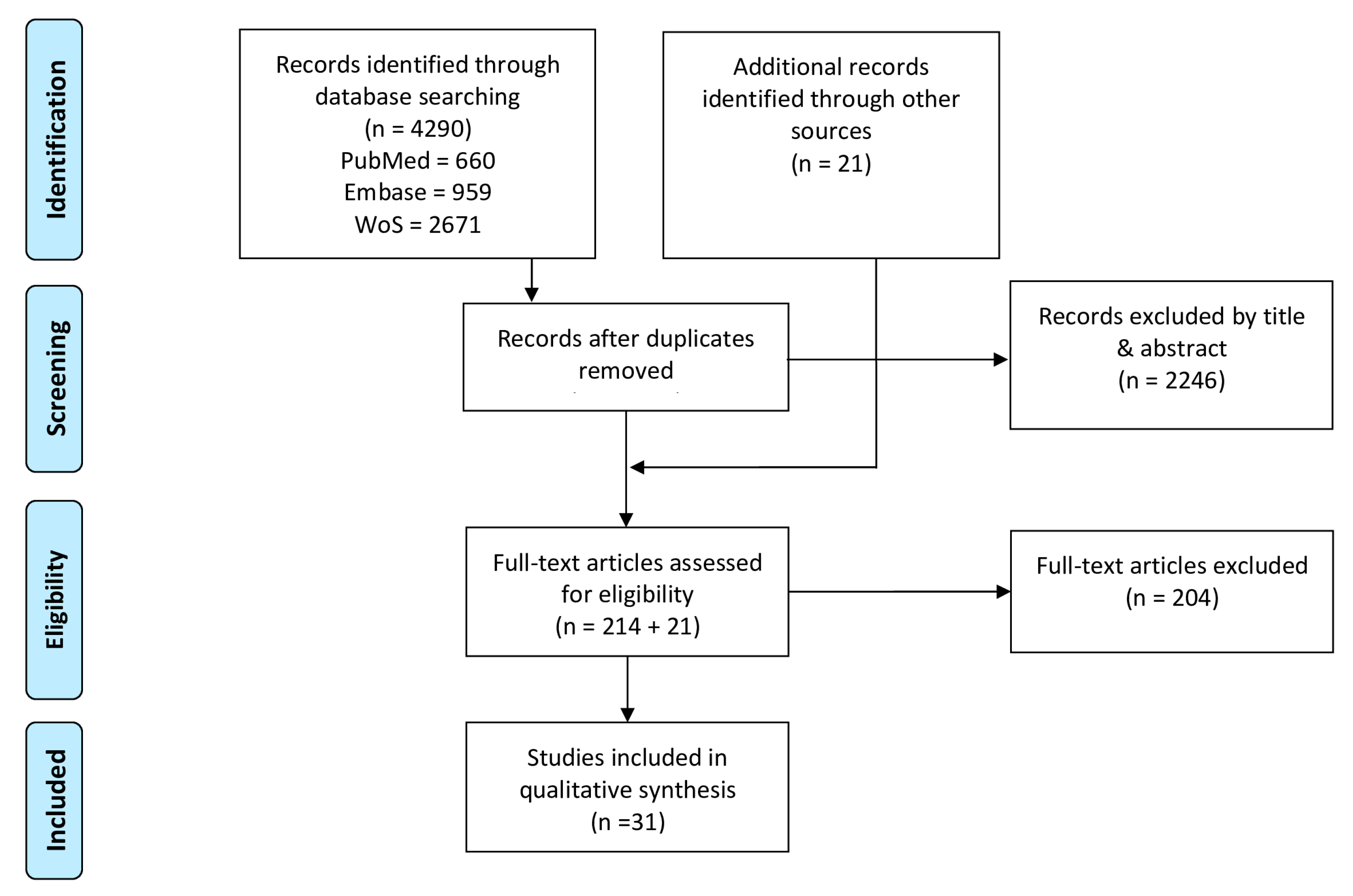
The available literature was searched in a systematic way through a personalized four step PRISMA method (Preferred Reporting Items for Systematic review and Meta-Analyses). These four steps are summarized in Figure 1. A systematic literature search in three databases (PubMed, Web of Science, EMBASE) covering a broad range of both medical and engineering studies was conducted. The literature was updated on a monthly basis until the end of September 2019. The search strategy and combinations of keywords for the different databases are described in Appendix A. After the removal of duplicates, the remaining records were screened on title and abstract and assessed for eligibility. Additionally, references of included articles were screened to ensure inclusion of all relevant studies.
2.3. Data Extraction
Data from all selected articles were extracted and are structured in Table 1, Table 2 and Table 3. The following information was extracted: (1) study characteristics (Table 1) covering participant information, the activity assessed, activity duration and the joints of interest with their investigated degrees of freedom (DoF). Additionally, sensor placement and the used sensor modalities contribute to the study characteristics, where sensor modalities refers to the raw sensor data that are used in the algorithm. Later in the article, IMU will be used for inertial measurement units which can measure specific force, angular velocity and sometimes magnetic field strength. (2) Signal processing characteristics (Table 2) describing the process to obtain meaningful kinematic measures from measured sensor data. This process is divided into pre-processing, the additional assumptions that have been made and the signal processing techniques that are used to extract the kinematic measures. The pre-processing is related both to sensor calibration as well as to filtering of the raw sensor signals. Later in the article, priors and assumptions will be defined as follows—prior information relates to information acquired by ether auxiliary apparatus or estimated by IMU measurements, while assumptions relate to a certain hypothesis made. Signal processing techniques describe how to cope with sensor to segment calibration, orientation initialization, sensor fusion and drift compensation. (3) The study results (Table 3) summarize the accuracy of the proposed methods against a reference system.
3. Results
The results of our systematic literature search initially identified 4290 articles of which thirty-one articles were ultimately included. Extracted information of included studies on study characteristics (Table 1), signal processing characteristics (Table 2) and study results (Table 3) are covered in respectively Section 3.1, Section 3.2 and Section 3.3.
3.1. Study Characteristics
The study characteristics summarized in Table 1 cover participant information, protocol of the conducted study and sensor set-up. Only four out of the thirty-one included studies involved more than ten participants [16,17,18,19]. Furthermore, a predominantly healthy population was recruited, except for identified populations with ankle osteoarthritis [17], transfemoral amputation [20], incomplete spinal cord injury [21], children with cerebral palsy (CP) [19] and stroke patients [22].
Among the thirty-one studies included in this review, gait was the most commonly evaluated activity, which was assessed either on a treadmill [16,17,23,24] or a walkway [20,21,22,25,26,27,28,29,30,31,32,33,34,35,36,37,38]. Functional movements (i.e., sit-to-stand, squat) are the next most common activities [18,19,32,39,40,41]. Furthermore, seven studies focused on more dynamic types of locomotion such as common daily activities [24] and sports, including ski racing [42], running [38,43,44], standing long jump [45] and cycling [46]. Only nine studies reported kinematic analysis beyond 30s of recording [17,21,22,24,29,42,43,44,46].
Most articles did not study the full 3D kinematics of the entire lower quadrant. Sagittal knee joint movements were most extensively studied [21,23,36,40,43,44]. Furthermore, three studies extended such a hinge joint model to three DoF knee joint movements [25,26,29]. Two studies solely assessed the hip joint in two DoF [28] and three DoF [46]. Two studies solely focused on the ankle complex in three DoF [17,32]. Studies that incorporated multiple joints, also predominantly restrict movement analysis to the sagittal plane. To this end, most commonly assessed was the combination of the full sagittal lower limb (hip, knee, ankle) [24,30,31,34,38,41,45]. Second most common combination was the assessment of the sagittal knee and ankle joint movement [16,19,20,27].
Nearly all the studies made use of sensors placed on adjacent segments surrounding the joint of interest. Four studies opted for a more distal placement on the segments [18,22,35,37]. Only three out of thirty-one studies were able to provide a reproducible description of sensor placement based on anatomical landmarks [19,38,42]. Most of the studies only used three-axes gyroscopes and three-axes accelerometers [17,18,19,20,22,25,26,30,31,33,34,37,38,39,42,44]. Six studies additionally incorporated a magnetometer [24,29,32,43,45,46]. Moreover, four studies complemented IMU measurements with other modalities, such as a pressure sensor [21,24,36,45].
3.2. Signal Processing Characteristics
Signal processing characteristics (Table 2) were split up into three components. The first component covered pre-processing and the use of prior information and assumptions. Sensor readings are typically corrupted by measurement noise and bias. These noise and bias affected measures require a compensation in the form of pre-processing steps. The incorporation of prior knowledge and assumptions will further ease the calculation of kinematics. A second component summarized methods to combine pre-processed measurements from different sensor modalities with priors and assumptions, called information fusion. The third component described compensation mechanisms to account for integration drift, to initialize joint angles, and to cope with a natural misplacement of a sensor with respect to the boney landmarks.
3.2.1. Pre-Processing, Prior Information and Assumptions
Eight studies compensated for gyroscope bias [18,21,22,32,33,34,37,42]. Seven studies described a method for accelerometer calibration [16,18,22,32,33,38,42]. More extensive calibration procedures for inertial measurement units [47,48] were subsequently used in [18,22,32,38,42]. Raw inertial sensor measurements were often filtered. Most commonly, a Butterworth filter [19,21,32,34,39,46] was used. The filter orderwas chosen between 2 and 4. Cut-off frequencies differed between 2Hz and 20Hz, with the exception of [42], where information above 100 Hz was neglected.
The analysis of human motion yields biomechanically related prior information such as joint range of motion (RoM) [18,39,41], segment lengths [18,24,33,34,37,38,40,41,45] and spatiotemporal gait parameters [21,37]. Additionally, the indirect way of measuring kinematics with IMUs placed on the body segments required prior knowledge about the sensor position with respect to the joint center [23,24,29,40,46], sensor to segment alignment [17,29,34,37,40,44,46] and an initial sensor orientation or kinematic estimate [39,44]. Furthermore, three studies described a method to learn a fully subject-specific model [30,31,43].
Besides prior knowledge, specific assumptions were also exploited to ease the estimation of joint kinematics. Both a single description of joint acceleration in a common reference frame (up to a time-variant rotation matrix) and segment rigidity were often used as assumptions [20,23,28,29,33,35,36,38,42]. Furthermore, human motion was assumed to coincide with kinematic chain conventions [49,50] that describe how connected segments behave [18,22,37,39]. Seven studies assumed periodicity in the motion [16,17,22,30,38,39,41,45]. Moreover, three studies assumed symmetry between the right and left side of the subject [35,41,45].
3.2.2. Information Fusion
A set of common approaches for information fusion were identified in the thirty-one studies considered in this review. Strap-down integration was used [17,19,25,26,32,34,35,42,45] and characterized by Sabatini et al. [51] as “The attitude of the rigid body and its non-gravitational accelerations are sensed by gyroscopes and accelerometers strapped to the body.” Two studies followed a complementary filtering approach which acts in the frequency domain, to simultaneously filter high-frequency noise on the accelerometer inclination estimates and low-frequency noise on the integrated angular velocity relative orientation estimates [20,46]. Estimating sensor orientations is an inherently nonlinear problem. Five studies made use of nonlinear filtering techniques, such as an extended Kalman filter, to optimally fuse sensor measurements [18,22,24,37,44] or nonlinear numerical optimization [29,38,39] which makes use of all data samples to obtain a kinematic estimate.
Different from conventional information fusion methods, other methods were proposed for the application of joint kinematic estimation. For example, three studies used regression techniques to map raw sensor data to known kinematic parameters [30,31,43]. Furthermore in [33,40], motions were modeled as a moving pendulum to implicitly handle the fusion. Inverse kinematics were aided with accelerometer displacement estimates in [29,41,45]. Furthermore, Dejnabadi et al. [23] described joint angles at the joint center, based on the assumption of a common joint acceleration for one physical point. In contrast with information fusion, the use of only one sensor modality was exploited in six studies to overcome the need for fusion in accelerometer-only [16,27,28,36,40] and gyroscope-only methods [21].
3.2.3. Drift Compensation, Initialization and Calibration
Integration drift originates as an artifact by integration of noise- and bias-affected gyroscope measures. In this article, global and relative drift are defined as drift with respect to a global or an adjacent segment reference frame, respectively. Drift in the vertical plane was compensated by tilt estimates from accelerometer readings, which are dominated by gravity during characteristic samples [17,19,20,24,25,26,27,32,34,35,42]. Further drift compensation in the horizontal plane was achieved by utilizing magnetometer readings [32,46]. Two studies reported a resetting approach for azimuth angles in a cycle-by-cycle manner during mid-stance in gait [17,45]. Regardless of the movement plane, relative drift between segments is compensated by the incorporation of priors and assumptions. For example, imposing segments to be connected at all times [29] by imposing joint DoF boundaries [44] or RoM constraints [18]. Also, the incorporation of time periods when segments were connected to the ground [18,21,24,37,38] were used to reset to the known absolute inclinations at given time instances. Furthermore, distinguishing gravity from linear acceleration by modeling motion as a pendulum was used to prevent drift [46]. One study reported on the reduction of drift solely by means of filtering raw sensor measurements in a pre-processing step [34]. Furthermore, four studies reported the use of a periodicity [22,38,39,41] assumption to compensate for drift.
The information fusion techniques from Section 3.2.2 require the kinematics at the first instance to be initialized. A reasonable initialization can be obtained using prior knowledge. Six studies described the need for a static upright pose to obtain an initial orientation [16,25,26,27,29,42,45]. Three studies extended the latter by means of two different static poses [23,33,34]. Furthermore, magnetometer data were used to initialize the azimuth angle [29]. The initial difference between segments around the vertical was identified by means of ab/adduction movement [25,26]. Furthermore, two studies utilized auxiliary apparatus such as photogrammetric devices to initialize the sensor orientation [39,44].
To overcome misalignment between sensor and segments, different approaches were identified. Two studies aligned the sensor and segment with active [26] or passive [32] sagittal and frontal shank movements. One study extended calibration movements to application-dependent movements [42,52]. Five studies exploited prior knowledge to overcome sensor to segment misalignments [29,34,37,40,44,46]. In contrast to the aforementioned calibration methods, two studies assumed a perfect alignment between sensor and anatomical axis [21,23].
3.3. Study Evaluation and Results
Study validity with respect to a reference system is reported in Table 3. For the reader’s convenience, the least accurate results were considered in all studies that report multiple results for different activities or methodological parameters. When available, the results for healthy and pathological subjects were reported separately. Accuracy by means of root mean squared errors, mean absolute error or correlation coefficients of the estimated angles was reported with respect to a reference system. References systems other than an optical motion capture system consisted of an ultra-sound system [23], magnetic tracking device [25,26], flexible goniometer [16] and high definition cameras [42]. Two studies showed a disagreement in degrees of freedom in (Table 1) and the validated degrees of freedom [37,42]. Inconsistent accuracy results were reported for all joints of the lower limb. Sagittal plane motions for all studies were reported with mean RMSE values ranging between 1.3–11.22 degrees while frontal and transversal RMSE values ranged between 1–6.7 and 1.4–6.5 degrees, respectively.
4. Discussion
This review systematically evaluated the methodological requirements for IMU-based lower limb joint kinematic estimation. Human motion analysis with inertial sensors has the potential to increase understanding in movement patterns in trusted well-known environments [10]. However, from an engineering point of view, it is an ambitious goal that is currently the subject of research [1,12]. A general inconsistency in accuracy of the study results (Table 3) indicates that the signal processing characteristics summarized in Section 3.2 (Table 2) highly depend on the application (Table 1) of interest.
In summary, lower limb kinematic estimation from inertial sensors requires a well-defined application and study characteristics. The study characteristics define which sensor modalities will be measured and processed to compensate for the following sensor restrictions: (1) due to their microelectromechanical architecture, raw sensor measurements are prone to noise and non-zero biases; (2) an integration step of measurements is typically necessary to obtain joint kinematics, resulting in drifting estimates of sensor orientations and joint kinematics; (3) inertial sensors are usually not aligned with the bone, which implies that misalignment with respect to anatomical coordinate frames needs to be identified; (4) initial sensor orientations need to be determined.
In order to overcome these sensor restrictions, all of the included articles were required to rely in some way on application-specific prior information and assumptions. However, by including this additional information in the methodology, the resulting kinematic estimates need to be interpreted carefully, taking into consideration a number of factors, before drawing any clinical decision.
First, the biomechanical system yields usable prior information, but this information can be violated in practical applications. For example, assumptions on the range of motion can restrict the kinematic solution to be within a given interval of normal physical ability. However, RoM boundaries are not generalizable across patient populations who might be hypermobile or hypomobile, exceeding or not reaching normal RoM respectively. Also, segment lengths are relevant priors that can be obtained, as described by Crabolu et al. [56]. Multiple studies make use of an estimated vector that describes the position of the center of the joint in the sensor’s coordinate frame [57]. Such joint center position vectors implicitly assume that segments are rigid and connected at one common fixed point. However, possible small joint-translational movements and soft tissue artifacts will violate this model [58,59]. In reality, soft tissue artifacts are present when patients move [60]. Frick et al. [58,59] recently proposed a method that identifies the time variations of a joint center position vector due to soft skin movement, but lacks a proper validation. Ideally, prior knowledge is estimated from sensor measurements [20,46,56] rather than measured in a movement laboratory or obtained from anthropometric tables.
Second, assuming periodicity in motion dates back to Morris et al. [61], to solve for integration drift by making the beginning and ending of a gait trial equal [62]. Still, a more relaxed assumption on periodicity, instead of resetting, is more convenient [17]. Two studies compensate for integration drift in azimuth angles on a cycle-by-cycle manner during mid-stance in gait [17,45]. Nevertheless, the latter is not a measure of absolute heading and might lead to accumulating errors on the foot progression angle [63]. Along the same lines, symmetry assumptions can help to allow for reducing the number of sensors on the body [35,41], but might over-constrain the system. For example, Bonnet et al. [41] analyzed the execution of a squat movement with a symmetry assumption on the legs. The method intends to only use one sensor, placed at the lower back. However, by applying a symmetry assumption, frontal hip, knee, and pelvis motion are not assessed, while still very relevant in such transitional movements [64]. Multiple studies utilized a zero-acceleration assumption at the contact point of the foot with the ground and therefore expected one foot to be on to the ground on a regular basis. Note that such an assumption might become invalid when applied to movements that lack a regular mid-stance phase such as running or other arbitrary movements.
Moreover, calibration movements are typically required to obtain a misalignment matrix between the sensor and anatomical reference frames. However, predefined calibration movement with a fully extended leg can be difficult within certain patient populations or during post-op periods [25,42]. As a result, the precision of the calibration depends on the accuracy with which the subject or instructor performs the calibration movements. A trend towards calibration-free methods with arbitrary placement of sensors and the avoidance of calibration movements is visible [20,65,66].
The incorporation of additional information such as assumptions and prior information can easily be done in an optimization-based smoothing approach for applications that demand high accuracy [29,39]. Solving such problem in a smoothing way, implicitly uses all available data [29,38] instead of a one-way filtering approach with only samples of the past. On the other hand, biofeedback applications ask for computationally less expensive fusion methods that can provide real-time estimates such as complementary filters [54,67,68].
5. Future Research
This review highlights the application dependency and inherent connection of methodological characteristics for lower limb IMU-based kinematic estimation. Assumptions and prior information are typically used to compensate for sensor limitations and to enhance the quality of kinematic estimates. Because of this, IMU-based kinematic estimates have to be interpreted carefully, before drawing any clinical decision. We identified a number of directions and pieces of advice for future research for the estimation of clinically relevant lower limb kinematics.
5.1. Reporting Joint Kinematics
For the clinical interpretability of the joint kinematics, the general reporting standards from the International Society of Biomechanics (ISB) [69,70] need to be followed. Only seven out of thirty-one of the included articles mentioned these standards. Joint kinematics are described as the movement of a distal segment with respect to its proximal segment, following a joint coordinate system [71]. The following movements are clinically relevant: (1) flexion/extension movements in the sagittal plane that occurs around the proximal segment-fixed frontal axis; (2) internal/external movements around the body-fixed longitudinal axis of the distal joint describing movements in the transversal plane; (3) abduction and adduction movements around the floating axis perpendicular to the two previously mentioned axes, describing frontal plane movement.
5.2. Biomechanical Joint Modeling
Gait predominantly occurs in the sagittal plane, and therefore the knee is often modeled as a hinge joint. A hinge joint axis can be estimated from IMU readings [20,66] to compensate for the misalignment between sensor and bone, which allows for an arbitrary placement of the sensing units. However, smaller joint movement in frontal and transversal planes also occurs and plays a critical role in for example ligament injuries [72,73,74]. Investigation in more complex and even subject-specific tibiofemoral joint models with inertial sensors, may provide highly valuable inside in these secondary joint kinematics for outside laboratory applications [75].
Furthermore, a recent trend is visible towards the inclusion of multiple joints and segments, rather than estimating kinematics for separate joints [29,38,42]. When multiple sensors are exploited, common information can be used to improve kinematic estimates. In this case, an appropriate joint model needs to be chosen for each individual joint [76].
5.3. Validation with Respect to a Golden Standard Reference
Optical motion capture systems are the most commonly used technique to study lower limb movement. They are therefore also most often used as a reference to evaluate IMU-based joint kinematic estimation methods. However, due to manual marker placement errors [77] and soft tissue artifacts [5,78], a conventional 3D gait analysis system will introduce biases that are predominantly present in smaller frontal and transversal movements. These secondary joint kinematics yield valuable insight into ligament loading and ACL injury [72]. Stagni et al. [5] concluded that flexion/extension at the knee by means of optical external markers can be considered acceptably reliable. However, internal/external rotations and ab/adduction at the knee are critically affected by soft-tissue artifacts. In order to validate internal/external rotations and ab/adduction kinematic estimated by means of IMUs, alternative validation methods (i.e., biplanar radiographic imaging systems [79,80]) that might be superior in tracking underlying bone movements need to be examined.
5.4. Measurement Duration and Environment
Whilst IMUs are proposed for long term observations, there are still few studies tackling measurements beyond 30 s. With respect to long, in-the-wild studies, measurement duration must be increased [81,82,83]. Resolving this problem could potentially bring the use of IMUs closer to applications in which subjects can be monitored for hours or days, with bursts of activity in-between long in-activity periods [81,82,83]. To meet this requirement, a clear trend is visible towards magnetometer-free methods, only acquiring accelerometer and gyroscope readings. The authors of this review believe that this idea is important, specifically for outside-lab applicability (i.e., hospital environment, sports field), without the need for assumptions on magnetic field homogeneity.
5.5. Disturbed Movement Patterns
Most of the published work recruited young, healthy participants. However, in clinics, most attention must go to the investigation of different patient populations with disturbed daily functional movement such as gait, sit-to-stand, stand-to-sit or climbing stairs [64]. One of the crucial aspects here is the inability of the patient (e.g., patients with neuromotor disorders or people with severe limb disorders) to perform pre-defined calibration movements, often necessary for the evaluation of functional movements with IMUs. The eligibility criteria in Section 2.1 demand a reproducible description of the algorithm. This might have resulted in studies that lack extensive validation on disturbed movement patterns, which is often done in a later phase, e.g., [84]. Investigating disturbed movement patterns and calibration-free methods to cope with sensor-to-segment misalignment in different patient populations will be an important avenue of research.
6. Conclusions
This review systematically evaluated the methodological requirements for IMU-based lower limb joint kinematic estimation. Where are we now? Despite the ongoing research regarding the computation of joint kinematics by means of IMUs, there still appear to be difficulties which prevent their use in daily clinical practice. It is reasonable to assume that the complexity in obtaining meaningful kinematic measures from noisy and biased measured sensor data and sensor restrictions regarding integration drift, sensor-to-segment alignment and initial sensor orientation explain these study restrictions. What can already be measured with sufficient accuracy? Most often, biomechanically inspired assumptions and prior information are used to compensate for sensor limitations. Both clinicians and engineers have to be aware of the possible adaptations in the IMU-based kinematic estimates by incorporating such prior information and assumptions, before drawing clinical decisions. What needs to be tackled with high priority? Investigating the appropriate validation methods that might be superior in tracking underlying bone movement and can overcome the restrictions of optical motion capture systems as a reference. What might yield novel results? Subject-specific IMU-based biomechanical joint models applied to populations with disturbed movement patterns in real-world settings. Combined efforts of engineers and clinical experts can result in application- and patient-specific implementations that will be valuable to clinicians.
Author Contributions
Conceptualization, K.C. and I.W.; Methodology, I.W.; Formal Analysis, I.W.; Data Curation, I.W.; Writing—Original Draft Preparation, I.W., K.C., M.K. (Manon Kok); Writing—Review and Editing, M.K. (Marco Konings), M.K. (Manon Kok), H.D.V., H.H., K.C.; Supervision, K.C., M.K. (Manon Kok); Funding Acquisition, K.C. All authors have read and agreed to the published version of the manuscript.
Funding
This research was funded by the European Regional Development Fund (We-Lab for Health, Technology and Movement, project number 1047).
Conflicts of Interest
The authors declare no conflict of interest.
Appendix A
Combination of keywords:
Web Of Science
TS = (inertial measurement unit OR imu OR accelerometer OR magnetometer OR gyroscope OR inertial sensor*) AND TS = (kinematic* OR joint angle*OR joint angle velocity OR joint angle acceleration)
PubMed
‘((kinematic*[tiab] OR joint angle*[tiab] OR “joint angle velocity”[tiab])) AND (“inertial measurement unit”[tiab] OR imu[tiab] OR accelerometer[tiab] OR magnetometer[tiab] OR gyroscope[tiab] OR inertial sensor*[tiab])’
Embase
(‘kinematics’/exp OR ‘kinematic*’:ti,ab OR ‘joint angle*’:ti,ab OR ‘joint angle velocity’:ti,ab OR ‘joint angle acceleration’:ti,ab OR ‘joint angle’/exp) AND (‘inertial measurement unit’/exp OR ‘inertial measurement unit’:ti,ab OR ‘imu’:ti,ab OR ‘accelerometer’:ti,ab OR ‘magnetometer’:ti,ab OR ‘gyroscope’:ti,ab OR ‘inertial sensor*’:ti,ab OR ‘accelerometer’/exp OR ‘magnetometer’/exp OR ‘gyroscope’/exp)
References
- Benson, L.C.; Clermont, C.A.; Bošnjak, E.; Ferber, R. The use of wearable devices for walking and running gait analysis outside of the lab: A systematic review. Gait & Posture 2018, 63, 124–138. [Google Scholar] [CrossRef]
- Hosseini Nasab, S.H.; List, R.; Oberhofer, K.; Fucentese, S.F.; Snedeker, J.G.; Taylor, W.R. Loading Patterns of the Posterior Cruciate Ligament in the Healthy Knee: A Systematic Review. PLoS ONE 2016, 11, e0167106. [Google Scholar] [CrossRef] [PubMed]
- Camomilla, V.; Cappozzo, A.; Vannozzi, G. Three-Dimensional Reconstruction of the Human Skeleton in Motion. In Handbook of Human Motion; Springer International Publishing: Cham, Switzerland, 2018; pp. 17–45. [Google Scholar] [CrossRef]
- McGinley, J.L.; Baker, R.; Wolfe, R.; Morris, M.E. The reliability of three-dimensional kinematic gait measurements: A systematic review. Gait & Posture 2009, 29, 360–369. [Google Scholar] [CrossRef]
- Stagni, R.; Fantozzi, S.; Cappello, A.; Leardini, A. Quantification of soft tissue artefact in motion analysis by combining 3D fluoroscopy and stereophotogrammetry: A study on two subjects. Clin. Biomech. 2005, 20, 320–329. [Google Scholar] [CrossRef]
- Camomilla, V.; Bergamini, E.; Fantozzi, S.; Vannozzi, G. Trends Supporting the In-Field Use of Wearable Inertial Sensors for Sport Performance Evaluation: A Systematic Review. Sensors 2018, 18, 873. [Google Scholar] [CrossRef] [Green Version]
- Wagner, J.F. About Motion Measurement in Sports Based on Gyroscopes and Accelerometers - an Engineering Point of View. Gyroscopy Navig. 2018, 9, 1–18. [Google Scholar] [CrossRef]
- Filippeschi, A.; Schmitz, N.; Miezal, M.; Bleser, G.; Ruffaldi, E.; Stricker, D. Survey of Motion Tracking Methods Based on Inertial Sensors: A Focus on Upper Limb Human Motion. Sensors 2017, 17, 40. [Google Scholar] [CrossRef] [Green Version]
- Lopez-Nava, I.H.; Munoz-Melendez, A. Wearable Inertial Sensors for Human Motion Analysis: A Review. IEEE Sens. J. 2016, 16, 7821–7834. [Google Scholar] [CrossRef]
- van der Straaten, R.; De Baets, L.; Jonkers, I.; Timmermans, A. Mobile assessment of the lower limb kinematics in healthy persons and in persons with degenerative knee disorders: A systematic review. Gait & Posture 2018, 59, 229–241. [Google Scholar] [CrossRef]
- Fong, D.T.; Chan, Y.Y. The use of wearable inertial motion sensors in human lower limb biomechanics studies: A systematic review. Sensors 2010, 10, 11556–11565. [Google Scholar] [CrossRef] [PubMed] [Green Version]
- Picerno, P. 25 years of lower limb joint kinematics by using inertial and magnetic sensors: A review of methodological approaches. Gait & Posture 2017, 51, 239–246. [Google Scholar] [CrossRef]
- Iosa, M.; Picerno, P.; Paolucci, S.; Morone, G. Wearable inertial sensors for human movement analysis. Expert Rev. Med. Devices 2016, 13, 641–659. [Google Scholar] [CrossRef] [PubMed]
- O’Reilly, M.; Caulfield, B.; Ward, T.; Johnston, W.; Doherty, C. Wearable Inertial Sensor Systems for Lower Limb Exercise Detection and Evaluation: A Systematic Review. Sports Med. 2018, 48, 1221–1246. [Google Scholar] [CrossRef] [Green Version]
- Moher, D.; Liberati, A.; Tetzlaff, J.; Altman, D.G.; The, P.G. Preferred Reporting Items for Systematic Reviews and Meta-Analyses: The PRISMA Statement. PLOS Med. 2009, 6, e1000097. [Google Scholar] [CrossRef] [Green Version]
- Djuric-Jovicic, M.D.; Jovicic, N.S.; Popovic, D.B. Kinematics of Gait: New Method for Angle Estimation Based on Accelerometers. Sensors 2011, 11, 10571–10585. [Google Scholar] [CrossRef] [Green Version]
- Rouhani, H.; Favre, J.; Crevoisier, X.; Aminian, K. Measurement of multi-segment foot joint angles during gait using a wearable system. J. Biomech. Eng. 2012, 134, 061006. [Google Scholar] [CrossRef]
- Lin, J.F.S.; Kulić, D. Human pose recovery using wireless inertial measurement units. Physiol. Meas. 2012, 33, 2099–2115. [Google Scholar] [CrossRef]
- Choi, S.; Shin, Y.B.; Kim, S.Y.; Kim, J. A novel sensor-based assessment of lower limb spasticity in children with cerebral palsy. J. NeuroEng. Rehabil. 2018, 15, 16. [Google Scholar] [CrossRef] [Green Version]
- Seel, T.; Raisch, J.; Schauer, T. IMU-Based Joint Angle Measurement for Gait Analysis. Sensors 2014, 14, 6891–6909. [Google Scholar] [CrossRef] [Green Version]
- Tong, K.; Granat, M.H. A practical gait analysis system using gyroscopes. Med Eng. Phys. 1999, 21, 87–94. [Google Scholar] [CrossRef]
- Joukov, V.; Bonnet, V.; Karg, M.; Venture, G.; Kulic, D. Rhythmic Extended Kalman Filter for Gait Rehabilitation Motion Estimation and Segmentation. IEEE Trans. Neural Syst. Rehabil. Eng. 2018, 26, 407–418. [Google Scholar] [CrossRef]
- Dejnabadi, H.; Jolles, B.M.; Aminian, K. A new approach to accurate measurement of uniaxial joint angles based on a combination of accelerometers and gyroscopes. IEEE Trans. Biomed. Eng. 2005, 52, 1478–1484. [Google Scholar] [CrossRef]
- Slajpah, S.; Kamnik, R.; Munih, M. Kinematics based sensory fusion for wearable motion assessment in human walking. Comput. Methods Programs Biomed. 2014, 116, 131–144. [Google Scholar] [CrossRef]
- Favre, J.; Jolles, B.M.; Aissaoui, R.; Aminian, K. Ambulatory measurement of 3D knee joint angle. J. Biomech. 2008, 41, 1029–1035. [Google Scholar] [CrossRef]
- Favre, J.; Aissaoui, R.; Jolles, B.M.; de Guise, J.A.; Aminian, K. Functional calibration procedure for 3D knee joint angle description using inertial sensors. J. Biomech. 2009, 42, 2330–2335. [Google Scholar] [CrossRef]
- Djuric-Jovicic, M.D.; Jovicic, N.S.; Popovic, D.B.; Djordjevic, A.R. Nonlinear optimization for drift removal in estimation of gait kinematics based on accelerometers. J. Biomech. 2012, 45, 2849–2854. [Google Scholar] [CrossRef]
- Liu, K.; Liu, T.; Shibata, K.; Inoue, Y.; Zheng, R. Novel approach to ambulatory assessment of human segmental orientation on a wearable sensor system. J. Biomech. 2009, 42, 2747–2752. [Google Scholar] [CrossRef]
- Kok, M.; Hol, J.D.; Schon, T.B. An optimization-based approach to human body motion capture using inertial sensors. IFAC-PapersOnLine 2014, 47, 79–85. [Google Scholar] [CrossRef] [Green Version]
- Goulermas, J.Y.; Findlow, A.H.; Nester, C.J.; Liatsis, P.; Zeng, X.J.; Kenney, L.P.J.; Tresadern, P.; Thies, S.B.; Howard, D. An instance-based algorithm with Auxiliary Similarity Information for the estimation of gait kinematics from wearable sensors. IEEE Trans. Neural Netw. 2008, 19, 1574–1582. [Google Scholar] [CrossRef] [Green Version]
- Findlow, A.; Goulermas, J.Y.; Nester, C.; Howard, D.; Kenney, L.P.J. Predicting lower limb joint kinematics using wearable motion sensors. Gait & Posture 2008, 28, 120–126. [Google Scholar] [CrossRef]
- O’Donovan, K.J.; Kamnik, R.; O’Keeffe, D.T.; Lyons, G.M. An inertial and magnetic sensor based technique for joint angle measurement. J. Biomech. 2007, 40, 2604–2611. [Google Scholar] [CrossRef]
- Takeda, R.; Tadano, S.; Natorigawa, A.; Todoh, M.; Yoshinari, S. Gait posture estimation using wearable acceleration and gyro sensors. J. Biomech. 2009, 42, 2486–2494. [Google Scholar] [CrossRef] [PubMed] [Green Version]
- Tadano, S.; Takeda, R.; Miyagawa, H. Three Dimensional Gait Analysis Using Wearable Acceleration and Gyro Sensors Based on Quaternion Calculations. Sensors 2013, 13, 9321–9343. [Google Scholar] [CrossRef] [PubMed]
- Ohtaki, Y.; Sagawa, K.; Inooka, H. A method for gait analysis in a daily living environment by body-mounted instruments. JSME Int. J. Ser. C-Mech. Syst. Mach. Elem. Manuf. 2001, 44, 1125–1132. [Google Scholar] [CrossRef] [Green Version]
- Liu, T.; Inoue, Y.; Shibata, K. Measurement of Muscle Motion for Improving Accuracy of Body-mounted Motion Sensor. In Proceedings of the IEEE International Conference on Advanced Intelligent Mechatronics, Xi’an, China, 2–5 July 2008; IEEE: New York, NY, USA; pp. 1325–1330. [Google Scholar]
- Joukov, V.; Karg, M.; Kulic, D. Online Tracking of the Lower Body Joint Angles using IMUs for Gait Rehabilitation. In Proceedings of the IEEE International Conference on Engineering in Medicine and Biology Society; IEEE: New York, NY, USA, 2014; pp. 2310–2313. [Google Scholar]
- Dorschky, E.; Nitschke, M.; Seifer, A.K.; van den Bogert, A.J.; Eskofier, B.M. Estimation of gait kinematics and kinetics from inertial sensor data using optimal control of musculoskeletal models. J. Biomech. 2019. [Google Scholar] [CrossRef] [PubMed]
- Bonnet, V.; Joukov, V.; Kulic, D.; Fraisse, P.; Ramdani, N.; Venture, G. Monitoring of Hip and Knee Joint Angles Using a Single Inertial Measurement Unit During Lower Limb Rehabilitation. IEEE Sens. J. 2016, 16, 1557–1564. [Google Scholar] [CrossRef] [Green Version]
- Caroselli, A.; Bagala, F.; Cappello, A. Quasi-real time estimation of angular kinematics using single-axis accelerometers. Sensors 2013, 13, 918–937. [Google Scholar] [CrossRef]
- Bonnet, V.; Mazza, C.; Fraisse, P.; Cappozzo, A. Real-time estimate of body kinematics during a planar squat task using a single inertial measurement unit. IEEE Trans. Biomed. Eng. 2013, 60, 1920–1926. [Google Scholar] [CrossRef]
- Fasel, B.; Sporri, J.; Chardonnens, J.; Kroll, J.; Muller, E.; Aminian, K. Joint Inertial Sensor Orientation Drift Reduction for Highly Dynamic Movements. IEEE J. Biomed. Health Inform. 2017. [Google Scholar] [CrossRef]
- Frank, J.W.; Matteo, G.; Giovanni, B.; Erik, M.; Jasper, R.; Bert-Jan, F.v.B.; Peter, H.V. Estimation of Vertical Ground Reaction Forces and Sagittal Knee Kinematics During Running Using Three Inertial Sensors. Front. Physiol. 2018, 9. [Google Scholar] [CrossRef]
- Cooper, G.; Sheret, I.; McMillian, L.; Siliverdis, K.; Sha, N.; Hodgins, D.; Kenney, L.; Howard, D. Inertial sensor-based knee flexion/extension angle estimation. J. Biomech. 2009, 42, 2678–2685. [Google Scholar] [CrossRef] [PubMed] [Green Version]
- Ibata, Y.; Kitamura, S.; Motoi, K.; Sagawa, K. Measurement of three-dimensional posture and trajectory of lower body during standing long jumping utilizing body-mounted sensors. In Proceedings of the IEEE International Conference on Engineering in Medicine and Biology Society, Osaka, Japan, 3–7 July 2013; pp. 4891–4894. [Google Scholar] [CrossRef]
- Cockcroft, J.; Muller, J.H.; Scheffer, C. A Novel Complimentary Filter for Tracking Hip Angles During Cycling Using Wireless Inertial Sensors and Dynamic Acceleration Estimation. IEEE Sens. J. 2014, 14, 8. [Google Scholar] [CrossRef]
- Ferraris, F.; Grimaldi, U.; Parvis, M. Procedure for effortless in-field calibration of three-axis rate gyros and accelerometers. Sens. Mater. 1995. [Google Scholar]
- Tedaldi, D.; Pretto, A.; Menegatti, E. A robust and easy to implement method for IMU calibration without external equipments. In Proceedings of the Conference proceedings of IEEE International conference on Robotics and Automation, Hong Kong, China, 31 May–7 June 2014; pp. 3042–3049. [Google Scholar]
- Bruyninckx, H.; De Schutter, J. Symbolic differentiation of the velocity mapping for a serial kinematic chain. Mech. Mach. Theory 1996, 31, 135–148. [Google Scholar] [CrossRef]
- Uicker, J.J.J.; Denavit, J.; Hartenberg, R.S. An Iterative Method for the Displacement Analysis of Spatial Mechanisms. J. Appl. Mech. 1964, 31, 309–314. [Google Scholar] [CrossRef]
- Sabatini, A.M. Quaternion-based strap-down integration method for applications of inertial sensing to gait analysis. Med. Biol. Eng. Comput. 2005, 43, 94–101. [Google Scholar] [CrossRef]
- Fasel, B.; Sporri, J.; Schutz, P.; Lorenzetti, S.; Aminian, K. Validation of functional calibration and strap-down joint drift correction for computing 3D joint angles of knee, hip, and trunk in alpine skiing. PLoS ONE 2017, 12, e0181446. [Google Scholar] [CrossRef]
- Favre, J.; Jolles, B.M.; Siegrist, O.; Aminian, K. Quaternion-based fusion of gyroscopes and accelerometers to improve 3D angle measurement. Electron. Lett. 2006, 42, 612–614. [Google Scholar] [CrossRef]
- Mahony, R.; Hamel, T.; Pflimlin, J.M. Nonlinear complementary filters on the special orthogonal group. IEEE Trans. Autom. Control 2008, 53, 1203–1218. [Google Scholar] [CrossRef] [Green Version]
- Winter, D.A. Biomechanics and Motor Control of Human Movement. In Biomechanics and Motor Control of Human Movement; John Wiley & Sons: Hoboken, NJ, USA, 2009. [Google Scholar]
- Crabolu, M.; Pani, D.; Raffo, L.; Conti, M.; Cereatti, A. Functional estimation of bony segment lengths using magneto-inertial sensing: Application to the humerus. PLoS ONE 2018, 13. [Google Scholar] [CrossRef] [PubMed] [Green Version]
- Olsson, F.; Halvorsen, K. Experimental evaluation of joint position estimation using inertial sensors. In Proceedings of the 20th International Conference on Information Fusion, Xi’an, China, 10–13 July 2017; pp. 354–361. [Google Scholar]
- Frick, E.; Rahmatalla, S. Joint Center Estimation Using Single-Frame Optimization: Part 2: Experimentation. Sensors 2018, 18, 2563. [Google Scholar] [CrossRef] [PubMed] [Green Version]
- Frick, E.; Rahmatalla, S. Joint Center Estimation Using Single-Frame Optimization: Part 1: Numerical Simulation. Sensors 2018, 18, 1089. [Google Scholar] [CrossRef] [PubMed] [Green Version]
- Andriacchi, T.P.; Alexander, E.J. Studies of human locomotion: Past, present and future. J. Biomech. 2000, 33, 1217–1224. [Google Scholar] [CrossRef]
- Morris, J.R.W. Accelerometry—A technique for the measurement of human body movements. J. Biomech. 1973, 6, 729–736. [Google Scholar] [CrossRef]
- Grisetti, G.; Ku, X.; Mmerle, R.; Stachniss, C.; Burgard, W. A Tutorial on Graph-Based SLAM. IEEE Intell. Transp. Syst. Mag. 2010, 2, 31–43. [Google Scholar] [CrossRef]
- Lai, Y.-C.; Lin, H.-S.; Pan, H.-F.; Chang, W.-N.; Hsu, C.-J.; Renn, J.-H. Impact of foot progression angle on the distribution of plantar pressure in normal children. Clin. Biomech. 2014, 29, 196–200. [Google Scholar] [CrossRef]
- De Vroey, H.; Staes, F.; Deklerck, J.; Vereecke, E.; Van Damme, G.; Vanrenterghem, J.; Hallez, H.; Claeys, K. Comparing UKA and TKA lower limb kinematics during gait one year after surgery. In Proceedings of the 18th ESSKA Congress, Glasgow, UK, 9–12 May 2018; pp. 279–280. [Google Scholar]
- Taetz, B.; Bleser, G.; Miezal, M. Towards Self-Calibrating Inertial Body Motion Capture. In Proceedings of the Conference of IEEE International Conference on Information Fusion, Heidelberg, Germany, 5–8 July 2016; pp. 1751–1759. [Google Scholar]
- Olsson, F.; Seel, T.; Lehmann, D.; Halvorsen, K. Joint axis estimation for fast and slow movements using weighted gyroscope and acceleration constraints. arXiv 2019, arXiv:1903.07353. [Google Scholar]
- Madgwick, S.O.H.; Harrison, A.J.L.; Vaidyanathan, R. Estimation of IMU and MARG orientation using a gradient descent algorithm. In Proceedings of the 2011 IEEE International Conference on Rehabilitation Robotics, Zurich, Switzerland, 29 June–1 July 2011; pp. 1–7. [Google Scholar]
- Kok, M.; Schön, T.B. A Fast and Robust Algorithm for Orientation Estimation Using Inertial Sensors. IEEE Signal Process Lett. 2019, 26, 1673–1677. [Google Scholar] [CrossRef]
- Wu, G.; Cavanagh, P.R. ISB recommendations for standardization in the reporting of kinematic data. J. Biomech. 1995, 28, 1257–1261. [Google Scholar] [CrossRef]
- Wu, G.; Siegler, S.; Allard, P.; Kirtley, C.; Leardini, A.; Rosenbaum, D.; Whittle, M.; D’Lima, D.D.; Cristofolini, L.; Witte, H.; et al. ISB recommendation on definitions of joint coordinate system of various joints for the reporting of human joint motion—part I: Ankle, hip, and spine. J. Biomech. 2002, 35, 543–548. [Google Scholar] [CrossRef]
- Grood, E.S.; Suntay, W.J. A joint coordinate system for the clinical description of three-dimensional motions: Application to the knee. J. Biomech. Eng. 1983, 105, 136–144. [Google Scholar] [CrossRef] [PubMed]
- Andriacchi, T.P.; Dyrby, C.O. Interactions between kinematics and loading during walking for the normal and ACL deficient knee. J. Biomech. 2005, 38, 293–298. [Google Scholar] [CrossRef] [PubMed]
- Georgoulis, A.D.; Papadonikolakis, A.; Papageorgiou, C.D.; Mitsou, A.; Stergiou, N. Three-Dimensional Tibiofemoral Kinematics of the Anterior Cruciate Ligament-Deficient and Reconstructed Knee during Walking. Am. Int. J. Sports Med. 2003, 31, 75–79. [Google Scholar] [CrossRef] [PubMed]
- Hewett, T.E.; Myer, G.D.; Ford, K.R.; Heidt, R.S.; Colosimo, A.J.; McLean, S.G.; van den Bogert, A.J.; Paterno, M.V.; Succop, P. Biomechanical Measures of Neuromuscular Control and Valgus Loading of the Knee Predict Anterior Cruciate Ligament Injury Risk in Female Athletes: A Prospective Study. Am. Int. J. Sports Med. 2005, 33, 492–501. [Google Scholar] [CrossRef] [PubMed] [Green Version]
- Dzialo, C.M.; Pedersen, P.H.; Simonsen, C.W.; Jensen, K.K.; de Zee, M.; Andersen, M.S. Development and validation of a subject-specific moving-axis tibiofemoral joint model using MRI and EOS imaging during a quasi-static lunge. J. Biomech. 2018, 72, 71–80. [Google Scholar] [CrossRef] [PubMed] [Green Version]
- Donnelly, C.J.; Lloyd, D.G.; Elliott, B.C.; Reinbolt, J.A. Optimizing whole-body kinematics to minimize valgus knee loading during sidestepping: Implications for ACL injury risk. J. Biomech. 2012, 45, 1491–1497. [Google Scholar] [CrossRef]
- Szczerbik, E.; Kalinowska, M. The influence of knee marker placement error on evaluation of gait kinematic parameters. Acta Bioeng. Biomech. 2011, 13, 43–46. [Google Scholar]
- Callewaert, B.; Labey, L.; Leardini, A.; Bellemans, J.; Desloovere, K.; Scheys, L. High versus normal body-mass index: Effects On 3D kinematics and kinetics during daily-life motor tasks. Gait & Posture 2013, 38, S111. [Google Scholar] [CrossRef]
- Clément, J.; Dumas, R.; Hagemeister, N.; de Guise, J.A. Soft tissue artifact compensation in knee kinematics by multi-body optimization: Performance of subject-specific knee joint models. J. Biomech. 2015, 48, 3796–3802. [Google Scholar] [CrossRef]
- Clément, J.; de Guise, J.A.; Fuentes, A.; Hagemeister, N. Comparison of soft tissue artifact and its effects on knee kinematics between non-obese and obese subjects performing a squatting activity recorded using an exoskeleton. Gait & Posture 2018, 61, 197–203. [Google Scholar] [CrossRef]
- Von Marcard, T.; Henschel, R.; Black, M.J.; Rosenhahn, B.; Pons-Moll, G. Recovering Accurate 3D Human Pose in The Wild Using IMUs and a Moving Camera. In Computer Vision – ECCV 2018; Springer: Cham, Switzerland, 2018. [Google Scholar]
- Reenalda, J.; Maartens, E.; Homan, L.; Buurke, J.H. Continuous three dimensional analysis of running mechanics during a marathon by means of inertial magnetic measurement units to objectify changes in running mechanics. J. Biomech. 2016, 49, 3362–3367. [Google Scholar] [CrossRef] [PubMed]
- Reenalda, J.; Maartens, E.; Buurke, J.H.; Gruber, A.H. Kinematics and shock attenuation during a prolonged run on the athletic track as measured with inertial magnetic measurement units. Gait & Posture 2019, 68, 155–160. [Google Scholar] [CrossRef]
- Teufl, W.; Miezal, M.; Taetz, B.; Frohlich, M.; Bleser, G. Validity, Test-Retest Reliability and Long-Term Stability of Magnetometer Free Inertial Sensor Based 3D Joint Kinematics. Sensors 2018, 18, 1980. [Google Scholar] [CrossRef] [Green Version]
Figure 1.
Preferred Reporting Items for Systematic review and Meta-Analyses (PRISMA) flowchart of the search strategy and study selection procedure, adapted from [15].
Figure 1.
Preferred Reporting Items for Systematic review and Meta-Analyses (PRISMA) flowchart of the search strategy and study selection procedure, adapted from [15].


Table 1.
Study characteristics.
| Ref. | Participants | Protocol | Sensor Set-Up | ||||
|---|---|---|---|---|---|---|---|
| Number and Sex, Type, Age | Activity | Duration | DoF Joint of Interest | Placement | Modalities | ||
| [23] | 5M 3F, healthy, | Gait (Treadmill) | 30s | 1DoF knee | thigh, shank | 1D GYR, 2D ACC | |
| range: 44-70 mean = 58.7 | (2–4 km/h) | ||||||
| [25] | 10M, healthy, | Gait | 10s | 3DoF knee | thigh, shank | 3D GYR, 3D ACC | |
| range: 23-40 mean = 29 | |||||||
| [26] | 8M, healthy, | Gait | 5s * | 3DoF knee | thigh, shank | 3D GYR, 3D ACC | |
| range 19–28 mean = 26 | |||||||
| [16] | 27, healthy, | Gait (Treadmill) (0,15 m/s–2 m/s) | 6s * | 1DoF knee, | thigh, shank, foot | 2× 2D ACC | |
| mean = 26 SD = 1,5 | 1DoF ankle | ||||||
| [27] | 10, healthy, | Gait | 3s * | 1DoF knee, | thigh, shank, foot | 2× 2D ACC | |
| mean = 31 SD = 4 | (slow, normal, fast) | 1DoF ankle | |||||
| [28] | 6M 2F, healthy, | Gait | 10s * | 2DoF hip | close to the hip, thigh | 2× 3D ACC, | |
| mean = 25 SD = 3 | (slow, normal, fast) | 1× 3D ACC | |||||
| [42] | 6, European cup level alpine ski racers, ND | Alpine ski racing | 90s * | 3DoF hip, | sternum, sacrum, thigh (lateral mid-distance between the knee and hip joint center), shank (tibial plateau) | 3D GYR, 3D ACC | |
| 3DoF knee | |||||||
| [29] | ND | Gait | 35s * | 3DoF knee | pelvis, thigh, shank, foot | 3D GYR, 3D ACC, 3D MAG | |
| [30] | 8, healthy, ND | Gait | ND | 1DoF hip, | shank, foot | 3D GYR, 3D ACC | |
| (slow, normal, fast) | 1DoF knee, | ||||||
| 1DoF ankle | |||||||
| [31] | 8, healthy, ND | Gait | 12s * | 1DoF hip, | shank, foot | 3D GYR, 3D ACC | |
| (self-selected speed) | 1DoF knee, 1DoF ankle | ||||||
| [43] | 8M, healthy experienced runners, mean = 25.1 SD = 5.2 | Running (Treadmill) | 180s | 1DoF knee | pelvis, shank | 3D GYR, 3D ACC, 3D MAG | |
| (10 km/h–14 km/h) | |||||||
| [32] | 2M, healthy, range: 23–25 | Leg exercises, gait | 8s * | 3DoF ankle | 3DoF ankle | 3D GYR, 3D ACC, 3D MAG | |
| [40] | 1M, ND, 29 | Squat | 11s * | 1DoF knee | thigh, shank | 1D ACC | |
| [20] | 1, transfemoral amputee, 40 | Gait | 6s * | 1DoF knee, 1DoF ankle | thigh, shank, foot | 3D GYR, 3D ACC | |
| [33] | 3M, healthy, range: 23–28 | Gait | 10s * | 2DoF hip, 1DoF knee | thigh, shank | 3D GYR, 3D ACC | |
| [34] | 5M, healthy, range: 22–27 | Gait | ND | 1DoF hip, 1DoF knee, 1DoF ankle | pelvis, thigh, shank, foot | 3D GYR, 3D ACC | |
| [24] | 5M, healthy, mean = 27.6 SD = 3.4 | Gait (Treadmill), | 15min | 1DoF hip, 1DoF knee, 1DoF ankle | lower back, thigh, shank, foot | 3D GYR, 3D ACC, 3D MAG, pressure insoles | |
| Stair walking | |||||||
| [35] | 6, healthy, > = 18 | Gait | ND | 1DoF hip, 1DoF knee | center of lumbar, thigh (most distal), shank (most distal) | 1D ACC, 1D GYR | |
| (Cadence range: 60-120 step/min) | |||||||
| [36] | 1, healthy, ND | Gait (self-selected speed) | 2s * | 1DoF knee | thigh, shank | 2 × 3D ACC, PSECR insole | |
| [17] | 7F 3M/3F 9M, healthy/unilateral ankle osteoarthritis, mean = 60 SD = 15/mean = 61 SD = 13 | Gait (Treadmill) | 5min | 3DoF shank-hindfoot, 3DoF hindfoot-forefoot, 3DoF shank-forefoot, 3DoF forefoot-toes | shank, hindfoot, forefoot, toes | 3D GYR, 3D ACC | |
| (2 km/h–5 km/h) | |||||||
| [45] | 1M, healthy, 23 | Standing | 5s * | 1DoF hip, 1DoF knee, 1DoF ankle | chest, right thigh, right shank | 3D GYR, 3D ACC, 3D MAG, pressure insole | |
| long jump | |||||||
| [18] | 12M 8F, healthy, mean = 23 | Functional rehabilitation exercises | ND | 3DoF (stationary base), 2DoF knee, 1DoF | hip (height of the anterior superior iliac spine), thigh (near the knee), calf (near the ankle) | 3D GYR, 3D ACC | |
| [41] | 5M 3F, healthy, mean = 32.5 SD = 9.9 | Squat | ND | 1DoF hip, 1DoF knee, 1DoF ankle | lower back | 1D GYR, 2D ACC | |
| [39] | 9M 1F, healthy, mean = 25 SD = 3 | Functional exercise | ND | 3DoF hip, 1DoF knee | shank | 1D GYR, 2D ACC | |
| [37] | 5, healthy, range: 19–25 | Gait | ND | 3DoF hip, 1DoF knee, 1DoF ankle | waist, hip, knee | 3D GYR, 3D ACC | |
| [46] | 1, ND, ND | Cycling | 5min | 3DoF hip | pelvis, thigh | 3D GYR, 3D ACC, 3D MAG | |
| [21] | 2, 1 healthy and 1 incomplete SCI subject, ND | Gait | 50s * | 1DoF knee | thigh, shank | 1D GYR, FSR | |
| [19] | 5 healthy/28 CP, 3M 2F/17M 3M 2F/17M 11F, healthy/CP, mean = 26 SD = 2.0/(18 subjects mean 7.5 sd = 3.1 and 10 subjects mean 5.5 sd 3.5) | Leg movements in supine position | 30s * | 1DoF knee, 1DoF ankle | thigh, shank, foot | 3D GYR, 3D ACC | |
| [22] | 3 and 2, healthy and stroke patients, ND and rang: 67:77 | Gait | 80s | 3DoF hip, 1DoF knee | pelvis, thigh, shank | 3D GYR, 3D ACC | |
| [44] | 5M 3F, healthy, mean = 30 SD = 6 | Gait, running | 5min | 1DoF knee | thigh, shank | 3D GYR, 3D ACC | |
| [38] | 10M, healthy, mean = 27.1 sd = 2.6 | Gait, running | ND | 1DoF hip, 1DoF knee, 1DoF ankle | lower back, lateral thigh, lateral shank, and upper midfoot. | 3D GYR, 3D ACC | |
Abbreviations: ND = not described; N/A = not applicable; M = Men; F = Female; SD = standard deviation; GYR = gyroscope; ACC = accelerometer; MAG = magnetometer; D = Dimensions (number of sensitive axes); DoF = degree of freedom; * = activity duration not explicitly mentioned, based on time axis of plots incorporating sampling frequencies; PSECR = pressure sensitive electric conductive rubber; SCI = incomplete spinal cord injured; FSR = force sensitive resistors.
Table 2.
Signal processing characteristics.
| Ref. | Pre-Processing | Additional Information | Signal Processing | ||||
|---|---|---|---|---|---|---|---|
| Sensor Calibration | Filter, Type, Order, Cut-Off, Input Data | Prior Knowledge | Assumptions | Initialization and Sensor-Segment Alignment | Information Fusion | Drift Compensation | |
| [23] | ND | Savitzky-Golay, LP, 3, ND, GYR ACC | Position sensor w.r.t. joint center (Photography) | Same acceleration in joint center, Sensor-to-segment mounting assumptions | (INI) Static: 5s (knees extended) and 5s (knees flexed) (S-S) assumptions | Virtual sensors in joint center | N/A |
| [25] | ND | ND | ND | ND | (INI) Static: 10s stand still, Functional: hip AA. | Strap-down integration [53] | ACC gravity compensation, during characteristic samples |
| [26] | ND | ND | ND | ND | (INI) Static: stand still Functional: hip AA, (S-S) Passive shank movements in frontal and sagittal plane | Strap-down integration [53] | ACC gravity compensation, during characteristic samples |
| [16] | ACC | ND | ND | Tangential and centripetal acceleration from redundant ACC set-up, Periodicity | (INI) Static: 2s stand still before and after a trial | N/A | BP filtering |
| [27] | ND | ND | Position sensor w.r.t. joint center | Tangential and centripetal acceleration from redundant ACC set-up | (INI) Static: 2s stand still before and after a trial | N/A | ACC gravity compensation, during characteristic samples, Nonlinear optimization |
| [28] | ND | ND, LP, ND, 20Hz, ACC | Position sensor w.r.t. joint center | Tangential and centripetal acceleration from redundant ACC set-up, Same acceleration in joint center | ND | N/A | N/A |
| [42] | GYR, ACC [47] | ND, LP, ND, 100, GYR ACC | ND | Same acceleration in joint center | (INI) Static: stand still (S-S)[52] | Strap-down integration [53] | ACC gravity compensation, during characteristic samples, Multi-sensor drift correction |
| [29] | GYR | ND | Manual measuring: Orientation sensor on body segment, Position sensor w.r.t. joint center | Segments are connected to each other at all time and Sensors can move slightly w.r.t. body segment | (INI) Static: stand still pose (ACC and MAG) (S-S) prior information | Constraint optimization, Strap-down integration | Exploit assumptions |
| [30] | ND | ND | Subject specific trained model | Periodicity | ND | Regression: GRNN | N/A |
| [31] | ND | ND | Subject specific trained model | ND | ND | Regression: GRNN | N/A |
| [43] | ND | (No inertial data was filtered) | Subject specific trained model | ND | ND | Regression: ANN, two-layer (250 and 100 neurons) | N/A |
| [32] | GYR, ACC [47] | Butterworth, LP, 2, 5Hz, ACC GYR | ND | Assume same discrepancies in magnetic field interference for both segments | (S-S) Functional: two leg movements. | Strap-down integration | ACC gravity compensation, during characteristic samples, MAG readings |
| [40] | ND | ND | Stereo-photogrammetric: Segment lengths, Orientation sensor on body segment, Position sensor w.r.t. joint center | Feet are supposed rigidly connected to the ground, Pendulum motion | (S-S) prior information | N/A | N/A |
| [20] | ND | ND | ND | Same acceleration in joint center | N/A | Complementary filter | Exploit assumptions |
| [33] | GYR, ACC | Moving average, LP, ND, 15 point at 100Hz, ACC GYR | Segment lengths | Same acceleration in joint center, Pendulum motion thigh around the hip, constant velocity in walking speed | (S-S) Static: two poses (standing upright and sitting flat with outstretched legs) | Pendulum model | N/A |
| [34] | GYR | Butterworth, LP, 4, 12Hz, GYR | Segment lengths, Orientation sensor on body segment (sagittal image) | ND | (INI) Static: two poses (standing upright and sitting flat with outstretched legs) (S-S) prior knowledge | Strap-down integration | ACC gravity compensation, during characteristic samples |
| [24] | ND | ND | Optical reference: Segment lengths, Position sensor w.r.t. joint center | One foot on the ground at all time with zero acceleration at contact point. | ND | Recursive EKF | ACC gravity compensation, during characteristic samples, Exploit assumptions |
| [35] | ND | ND | Position sensor w.r.t. joint center | Symmetry, Drift linearly accumulates during integration, ACC measured most distal at a segment equals the joint center acceleration, Same acceleration in joint center | ND | Strap-down integration | ACC gravity compensation, during characteristic samples, Modeling and correcting drift as linear accumulating |
| [36] | ND | ND, BP, ND, function of PSECR skin motion frequency content, ACC | Position sensor w.r.t. joint center, total pressure, CoP between sensor and skin | Same acceleration in joint center | ND | N/A | N/A |
| [17] | ND | ND | Orientation sensor on body segment (Optical motion capture system) | Periodicity | (S-S) prior information | Strap-down integration | ACC gravity compensation, during characteristic samples, Azimuth zeroing cycle-by- cycle. |
| [45] | ND | ND | Segment lengths | Symmetry, Periodicity | (INI) Static: stand still pose. | Strap-down integration, displacement from ACC double integration | Exploit assumption Symmetry |
| [18] | GYR, ACC [47] | ND | Segment lengths (Optical motion capture system), RoM, (anthropometric data) | DH convention | ND | EKF | Exploit assumptions & prior information |
| [41] | ND | ND | Segment lengths, RoM | Periodicity, perfect sagittal symmetry | ND | Inverse kinematics, displacement from ACC double integration | Exploit assumptions |
| [39] | ND | Butterworth, LP, ND, 2Hz, squared GYR | RoM, Segment lengths (manually measured), Initial joint angle (measured by goniometer) | Periodicity, DH convention | (INI) prior information | Constraint optimization | Exploit assumptions |
| [37] | GYR | ND | Segment lengths, Orientation sensor on body segment, (Manual annotation) Spatio-temporal data. | One foot on the ground at all time, kinematic chain model [49] | (S-S) prior information | EKF | Exploit assumptions |
| [46] | ND | Butterworth, LP, 4, 15Hz, ACC | Position sensor w.r.t. joint center, Orientation sensor on body segment | Pendulum motion of thigh segment around the hip CoR | (S-S) prior information | Adapted complimentary filter [54] | Exploit assumptions, MAG readings |
| [21] | GYR | Butterworth, LP, 4, 4Hz, GYR | Spatio-temporal data (FSR measurements) | Sensor-to-segment mounting assumptions | (S-S) assumptions | N/A | HP filtering kinematic estimates, resetting during mid-stance in gait cycle. |
| [19] | ND | Butterworth, LP, 2, 10Hz, GYR ACC | ND | Movements outside sagittal plane occur only at full extension | ND | Strap-down integration | ACC measuring gravity during characteristic samples. Correction for movements outside of sagittal plane. |
| [22] | GYR, ACC [48] | ND, LP, ND, 10Hz, GYR ACC | ND | Periodicity, kinematic chain model [49] | ND | Adapted EKF | Exploit assumption Periodicity |
| [44] | ND | ND | Sensor orientation difference adjacent segments, Initial sensor orientation (Optical motion capture system) | ND | (CAL and S-S) prior information | EKF | Exploit Joint DoF constraint. |
| [38] | GYR, ACC [47] | ND | Segment masses, measured segment lengths, center of mass locations, moments of inertia [55] | Periodicity, constrain translational joint movement | (S-S) ND (I-I) initial guess | Constraint optimization | Exploit assumptions |
Abbreviations: ND = not described; N/A = not applicable; GYR = gyroscope; ACC = accelerometer; AA = Abduction Adduction; LP = Low Pass; BP = Band Pass; S-S = Sensor to Segment alignment; INI = initial orientation; MAG = magnetometer; GRNN = General Regression Neural Network; ANN = Artificial Neural Network; EKF = Extended Kalman filter; PSECR = pressure sensitive electric conductive rubber; CoP = Center of Pressure; DH = Denavit-Hartenberg; RoM = Range of Motion; DoF = Degrees of Freedom.
Table 3.
Study results.
| Ref. | Reference | Accuracy | |||
|---|---|---|---|---|---|
| Method | Joint [Measure, Unit] | Sagittal | Frontal | Transversal | |
| [23] | Ultra-sound based motion measurement | knee [RMSE, deg] | 1.3 | ||
| [25] | Magnetic tracking device | knee [RMSE mean (SD), deg] | 1.5 (0.4) * | 1.7 (0.5) * | 1.6 (0.5) * |
| [26] | Magnetic tracking device | knee [RMSE mean (SD), deg] | 1.3 (0.5) * | 2.0 (0.6) * | 2.0 (0.9) * |
| [16] | Flexible goniometer | knee [RMSE median, deg] | 5 | ||
| ankle [RMSE median, deg] | 3.5 | ||||
| [27] | Optical motion capture system | knee [RMSE median, deg] | 3 | ||
| ankle [RMSE median, deg] | 2.8 | ||||
| [28] | Optical motion capture system | hip [RMSE, deg] | 4.1 | 4.9 | |
| [42] | High definition camera’s | hip [RMSE, deg] | 6.0 (1.5) * | ND | ND |
| knee [RMSE, deg] | 4.8 (1.7) * | ND | ND | ||
| [29] | Optical motion capture system | knee | graph only | graph only | graph only |
| [30] | Optical motion capture system | hip | *,*,* | ||
| knee | *,*,* | ||||
| ankle | *,*,* | ||||
| [31] | Optical motion capture system | hip [correlation] | (0.7-0.89) *,*,* | ||
| knee [correlation] | (0.7-0.89) *,*,* | ||||
| ankle [correlation] | (0.7-0.89) *,*,* | ||||
| [43] | Optical motion capture system | knee [mean RMSE, deg] | <5 *,*,* | ||
| [32] | Optical motion capture system | ankle [RMSE, deg] | [0,1] *,* | [1–2.5] *,* | [2.5–4.5] *,* |
| [40] | Mechanical pendulum setup and Optical motion capture system | knee [RMSE mean (SD), deg] | 1.01 (0.11) | ||
| [20] | Optical motion capture system | knee [RMSE healthy|prosthesis mean (SD), deg] | 3.30 (1.20)|0.71 (0.19) | ||
| Ankle [RMSE healthy|prosthesis, deg] | 1.62 (0.57)|0.81 (0.16) | ||||
| [33] | Optical motion capture system | hip [RMSE, deg] | 8.72 | 4.96 | |
| knee [RMSE, deg] | 6.79 | ||||
| [34] | Optical motion capture system | hip [RMSE, deg] | 10.14 | ||
| knee [RMSE, deg] | 7.88 | ||||
| ankle [RMSE, deg] | 9.75 | ||||
| [24] | Optical motion capture system | hip (median over all described conditions, deg) | <5 | ||
| knee (median over all described conditions, deg) | <5 | ||||
| ankle (median over all described conditions, deg) | <5 | ||||
| [35] | Optical motion capture system | hip [RMSE mean (SD), deg] | 5.24 (0.27) | ||
| knee [RMSE mean (SD), deg] | 11.22 (1.09) | ||||
| [36] | Optical motion capture system | knee | graph only | ||
| [17] | Optical motion capture system | shank-hindfoot, hindfoot-forefoot, shank-forefoot, forefoot-toes [RMSE, deg] | [1.4; 2] | [1.4; 2] | [1.4; 2] |
| [45] | Optical motion capture system | hip [RMSE, deg] | 3.92 | ||
| knee [RMSE, deg] | 7.87 | ||||
| ankle [RMSE, deg] | 3.22 | ||||
| [18] | Optical motion capture system | hip [RMSE mean, deg] | 4.3 | 6.5 | 6.5 |
| knee [RMSE mean, deg] | 4.3 | 6.5 | |||
| ankle [RMSE mean, deg] | 4.3 | ||||
| [41] | Optical motion capture system | hip [RMSE mean (SD), deg] | 3.1 (0.9) | ||
| knee [RMSE mean (SD), deg] | 2.0 (1.0) | ||||
| ankle [RMSE mean (SD), deg] | 3.2 (1.0) | ||||
| [39] | Optical motion capture system | hip [RMSE mean (SD), deg] | 3.6 (2.4) | 2.4 (1.0) | 2.7 (1.4) |
| knee [RMSE mean (SD), deg] | 4.0 (3.1) | ||||
| [37] | Optical motion capture system | hip | ND | ND | ND |
| knee [RMSE mean (SD), deg] | 6.20 (1.48) | ||||
| ankle | ND | ||||
| [46] | Optical motion capture system | hip [MAE, deg] | 0.8 | 6.7 | 2.2 |
| [21] | Optical motion capture system | knee [RMSE, deg] | 6.42 | ||
| [19] | Optical motion capture system | knee [RMSE, deg] | <3 | ||
| ankle [RMSE, deg] | <3 | ||||
| [22] | Optical motion capture system | hip [RMSE, deg] | 2.4 | 2.4 | 2.4 |
| knee [RMSE, deg] | 2.4 | ||||
| [44] | Optical motion capture system | knee [RMSE, deg] | |||
| [38] | Optical motion capture system | hip [RMSE mean (SD), deg] | 8.7 | ||
| knee [RMSE mean (SD), deg] | 5.3 | ||||
| ankle [RMSE mean (SD), deg] | 4.6 | ||||
Abbreviations: ND = not described; deg = degree; SD = standard deviation; *(precision) after removing an offset; *,* interpreted from box-plot *,*,* Inter and intra-subject dependent.
© 2020 by the authors. Licensee MDPI, Basel, Switzerland. This article is an open access article distributed under the terms and conditions of the Creative Commons Attribution (CC BY) license (http://creativecommons.org/licenses/by/4.0/).
Share and Cite
MDPI and ACS Style
Weygers, I.; Kok, M.; Konings, M.; Hallez, H.; De Vroey, H.; Claeys, K. Inertial Sensor-Based Lower Limb Joint Kinematics: A Methodological Systematic Review. Sensors 2020, 20, 673. https://0-doi-org.brum.beds.ac.uk/10.3390/s20030673
AMA Style
Weygers I, Kok M, Konings M, Hallez H, De Vroey H, Claeys K. Inertial Sensor-Based Lower Limb Joint Kinematics: A Methodological Systematic Review. Sensors. 2020; 20(3):673. https://0-doi-org.brum.beds.ac.uk/10.3390/s20030673
Chicago/Turabian StyleWeygers, Ive, Manon Kok, Marco Konings, Hans Hallez, Henri De Vroey, and Kurt Claeys. 2020. "Inertial Sensor-Based Lower Limb Joint Kinematics: A Methodological Systematic Review" Sensors 20, no. 3: 673. https://0-doi-org.brum.beds.ac.uk/10.3390/s20030673
Note that from the first issue of 2016, this journal uses article numbers instead of page numbers. See further details here.