Model Evaluation of the Influence of the Plunger Stroke on Functional Parameters of the Low-Pressure Pulse Gas Solenoid Injector


1
Faculty of Mechanical Engineering, Bialystok University of Technology, 45C Wiejska Str., 15-351 Bialystok, Poland
2
Doctoral School, Bialystok University of Technology, 45A Wiejska Str., 15-351 Bialystok, Poland
*
Author to whom correspondence should be addressed.
Sensors 2021, 21(1), 234; https://0-doi-org.brum.beds.ac.uk/10.3390/s21010234
Submission received: 29 November 2020
/
Revised: 20 December 2020
/
Accepted: 29 December 2020
/
Published: 1 January 2021
(This article belongs to the Section Physical Sensors)
Abstract
:The article presents a model-based evaluation of the impact of the plunger stroke on functional parameters of the low-pressure pulse gas solenoid injector. A reduced-order physics-based mathematical model was used to achieve this goal. The model was built on the basis of specified simplifications of the process, considering the forces that cause the plunger to move and the forces constituting resistance to its displacement. The implementation of a mathematical description in to the Matlab-Simulink environment allowed one to determine the characteristic values of operation of the Valtek Rail Type-30 injector, including plunger displacement courses. Calculations made with the assumption of the factory plunger stroke confirmed the validity of the model. The differences in opening and closing times were below 3% in comparison to the values given in the objects technical information. By assuming a specific plunger stroke, the functional relationships of opening and closing times were determined. The results showed a distortion of the force–response dependence for different plunger strokes. Results presented in the article can be used to support control-oriented modeling of systems incorporating pulsed gas dosing devices, such as combustion engines or gas turbines. More specifically, the proposed method can be used to pre-calibrate the delay time of the injector operation.
1. Introduction
Despite the unstable situation of the oil market, interest in alternative fuels used in transport, in particular liquefied petroleum gas (LPG), continues to grow [1,2]. The prevalence of gaseous fuels is also supported by legal regulations, i.e., Corporate Average Fuel Economy (CAFÉ), Alternative Motor Fuels Act (AMFA) [3,4], which is why their shares are growing [5]. On the other hand, the ubiquitous downsizing of engines [6] raises new challenges for alternative power systems. This is compounded by modifications to the combustion process, such as Controlled Auto-Ignition (CAI)/Homogeneous Charge Compression Ignition (HCCI) [7,8], High Pressure Direct Injection (HPDI), or Reactivity Controlled Compression Ignition (RCCI) [9], which are partly met by LPG systems using petrol injectors [10]. Emissions legislation concerning the vehicle homologation process is also a problem [11,12], in which Worldwide harmonized Light vehicles Test Cycle (WLTC) and Real Driving Emissions test (RDE) driving cycles play a dominant role [13]. A separate issue is the approval regulations for non-road and working machinery engines [14,15], where further restrictions are expected in the near future. All legislative actions, except for the reduction of toxic emissions of exhaust components, are aimed at reducing CO2 emissions [16,17], making it increasingly attractive to use methane or petroleum-based gaseous fuels [18,19,20,21,22].
The analyzed low-pressure, pulse gas injector is typically used in a wide range of Compressed Natural Gas (CNG) and (LPG) systems, including the latest generation of such solutions, combining the features of liquid and volatile phase injection (i.e., AC LLC STAG 500.4 [23]). The increasing popularity of new or retrofitted gas engines in certain European countries [2], boosts the rapid incremental development of such systems [24,25].
The main challenges pertaining to the development of gas injectors are the necessity to provide high fuel injection rates (over 300 times more fuel by volume compared to petrol engines) [26], and non-repeatability in injected fuel value (especially while approaching ballistic operation regime) [27,28]. There are high hopes of using a piezoelectric injector drive instead of a standard electromagnetic one, which will be able to improve the force–response relationship of the injector, as well as enable proper operation at times less than 2.5 × 10⁻³ s [29,30].
Computational simulation can help resolve the above challenges with considerable advantages to the level of insight and development time. The approaches used for modeling (gas) injectors can be divided into several categories depending on the level of physics involved and methods incorporated:
Thus, building a mathematical model of how the low pressure pulse gas solenoid injector works is a difficult task, but with some simplifying assumptions it is possible. A universal, simple mathematical model can be widely used in evaluating the functional parameters of an injector or testing new solutions (prototypes).
In such an approach, the mathematical model of the injector combines electrical, mechanical, and hydraulic sub-models. In the electrical part, the mathematical description focuses on the operation of the transistor key which controls the operation of the injector. This feature limits the current value when the injector is fully opened, which prevents it from heating [46], and is practically implemented as a Pulse-Width Modulation signal (PWM) signal [47,48]. The biggest problem in modeling the electrical part is determining the working parameters of the coil—mainly inductance. A large part of the mathematical model describing the operation of an electromagnetic circuit with a coil is based on an air coil without a movable core [49,50,51,52,53]. If it already tries to take into consideration the movable core, it is converted to an air coil in the end anyhow [54,55,56,57,58].
The movement of the injector plunger is the main aspect of analysis in the mechanical part [32,36,59]. A prime issue here is to estimate the friction parameters. The methods here involve the friction process [60] that can be applied and the aerodynamic drag force [61,62]. The hydraulic part is the calculation of the flow process through the injector [19,63]. The mathematical descriptions of hydraulic electro-valves can be successfully applied here [64].
Modeling the operation of the LPG vapor phase pulse injector specifically is not a common issue raised in scientific studies. The biggest problem boils down to determining the inductance of a coil with a moving core. The simplest method is to experimentally determine the inductance as a function of the displacement of a movable core [65]. Such an approach allows for differences in opening and closing times of the injector of 2.05% and 2.27% according to the manufacturer’s declaration. The dependency of inductance on the temporary value of voltage, resistance, and frequency of the excitation is presented, for instance, in the work of Borawski [38]. The verification of the whole model describing the operation of the gas injector was performed, by the mentioned authors, using the noncontact method. The Casio Exilim EX-FH100 fast camera was used for this purpose. The calculations were found to be consistent with the experimental studies, although one has to point out that the experimental matrix used for model validation was rather scarce.
Partial models of various phases of injector operation were also proposed [26,66]. Then, it allows for the possibility to describe, for instance, the course of current development or the disappearance of the nozzle flow. However, most of the partial models used in this approach are based on the characteristics obtained from experimental studies.
For that reason, it is necessary to develop a more complex and innovative mathematical model describing the operation of the LPG vapor phase pulse injector. Therefore, the authors propose an innovative approach in describing the inductance of the coil based on its geometric dimensions, material properties, and the momentary position of the movable core (plunger).
Bearing the above methodological development targets, the aim of the study was to assess the impact of the plunger stroke on the functional parameters of the pulse low-pressure gas injector. The opening and closing times were chosen as functional parameters, which determine the size of the fuel dose, and the time of its delivery. The obtained plunger displacement courses and the time shift of its occurrence in relation to the forced pulse are the basic information necessary in modeling the gas injection system. The mentioned characteristics can also be used for evaluating new gas fueling designs on the component and system level, as well as for retrofitting the engine to gas operation.
2. The Subject of the Modeling
The subject of modeling was a Valtek Rail Type-30 plunger injector (Figure 1).
It is an injector with impulse action, where in the normal position plunger 1 is pressed to corps 2 with spring 3. Without power supply, the flow valve is normally closed. When an electrical pulse appears on the coil 4 terminals, the solenoid circuit is closed using cramp 5. Plunger 1 moves into pilot 6 as far as the resistance caused by the limiter 7. When plunger 1 is raised, the gas flows from inlet nozzle 8 to outlet nozzle 9. When the power supply fails, the coil 4 is moved to the closed position using spring 3.
The flow rate of this type of injector is regulated by changing the opening time, outlet nozzle diameter, and plunger stroke. The last method is not recommended due to factory settings, but is feasible. As shown by the studies presented in [67], increasing the stroke increases the flow capacity. The technical data of the analyzed injector Valtek Rail Type-30 have been presented in Table 1.
3. Mathematical Modeling
The mathematical description of functioning of the gas injector was built on the basis of Figure 2. This is an upgrade of the mathematical model presented in [63] by the calculation part regarding the electromagnetic circuit in which the moving element is located inside the coil (modified description of the reluctance of the coil and, as a result, its inductance). In the paper [63], these parameters were defined by experimental results.
Due to the high complexity of construction during the creation of the mathematical description, simplifying assumptions presented below were made:
- the plunger position depends on the resultant forces acting in the system, the effect of reflection from elements susceptible in the return positions is omitted;
- the electromagnetic force results from the operation of the coil without interference;
- the force generated by the pressure spring is due to its stiffness and pretension, the vibrations are omitted;
- the force from the pressure is distributed evenly and depends on the characteristic area and plunger position;
- the friction force responsible for damping takes into consideration different components depending on the position and movement of the plunger;
- the drag force due to its low impact on plunger movement was omitted.
The state of equilibrium of the plunger based on (Figure 2) can be described:
Each of the force components affecting the plunger position depends on many functional parameters (coefficients) as well as the position and movement of the plunger itself. The first presented in Equation (1) is the electromagnetic force forcing the plunger to move. This force is the result of an electromagnetic coil and its value can be written as (Equation (2)):
The value of the electromagnetic force Fe is influenced by the current I supplying the coil and its inductance L. Due to the complexity of the entire electromagnetic circuit of Valtek Rail Type-30 injector and the ferromagnetic elements in its vicinity, the correct determination of the inductance is very difficult. An additional problem is to determine the changes of inductance as a function of plunger displacement or the frequency of electrical supply impulses. To calculate the current variation for the case of an electromagnetic circuit with a coil, the Faraday’s and Kirchhoff’s laws can be used (Equation (3)):
Additionally, in this case (Equation (3)), the calculated current value depends on the inductance and its variation as a function of plunger displacement. As mentioned earlier in the literature descriptions [24,47,49,50,51,52,53,69,70], the actuator coil is modeled as a normal coil with an air gap. The attempts to change to a version with a moving component inside the coil [54,55,56,58] are also based on the relations that describe a normal coil with an air gap.
They do not take into account the initial state of the plunger and even less the variability of inductance as a function of the plunger elevation, or the frequency of electrical supply pulses. The literature analysis concerning calculations of the inductance of an electromagnetic circuit with a moving core in the coil showed the lack of an unequivocal description considering the position of the core, properties of the materials used, or cramp asymmetry. Therefore, the article proposes an original approach. It consists of the fact that the commonly used (in literature) dependence describing the magnetic reluctance RM (Equation (4)) instead of operating with the distance from the core end (plunger) to the edge of the coil, the distance ac, which represents the distance from the center of mass to the edge of the coil, was proposed (Figure 3).
This is due to the fact that the plunger has an irregular shape and in its idle position is far from the coil edge. Additionally, Equation (4) considers the fact that there is an initial value of reluctance and as a result, inductance at the x = 0 m position, which was lacking in literature reports. The magnetic reluctance of the circuit according to Figure 3 can be calculated on the basis of a modified relation based on the previously presented literature dealing with the calculation of electromagnetic coils in the form of Equation (4).
where the average coil diameter Dm is defined as:
Having the RM magnetic reluctance value and the number of N turns in the coil, inductance can be written using Equation (6).
Taking as L`:
The final relation on the inductance can be written as Equation (8).
As a result, the inductance derivative was established as Equation (9).
In the case of a gas injector, frictional forces: static, kinetic, and viscous are responsible for damping the plunger movement. As mentioned in the simplifying assumptions, due to its small influence, the drag force was omitted. The general relationship to the friction force can be written as Equation (10):
When the plunger is still, the force of static friction (Equation (11)) affects it:
The pressure force FN can be taken at a level equivalent to that resulting from the plunger mass. This will represent a case where the injector will work in a horizontal position that can be applied in case of problems with the car body. The action of the solenoid should align the plunger with the pilot, which prevents its friction. However, with an asymmetrical cramp, the friction may intensify. The coefficient of friction is a characteristic of the mating surface. When the plunger moves, the static friction changes to the kinetic friction (Equation (12)) and the force of viscous friction (Equation (13)) occurs.
Both values of the friction forces Ffk and Ffv (Equations (12) and (13)) depend on the friction coefficients and are opposite to the direction of plunger movement. The resistance force of the plunger movement is also the spring force Fs (Equation (14)). The direction of this force is constant and its value depends on the stiffness k, preload x0, and plunger displacement x.
In position x = 0 mm the plunger is pressed by the pressure force Fg (Equation (15)). The value of this force depends on the surface area over A1 and under valve A2 (plunger) and the pressure value of gas p1 and inlet manifold p2. It is assumed that when the plunger is displaced by x > 1 × 10⁻⁷ mm, the pressure force fades away. The displacement tied to the pressure force fading away should be minimal and correlated with minimal steps of calculation.
In the analyzed case, the result of the calculation gives a plunger displacement. If the purpose of the calculation is flow parameters, the lumped element method can be used for this purpose [27], or the mathematical model presented in [64].
The last of the forces is the resistance force of mass inertia (Equation (16)). The value consists of the mass plunger m and its acceleration a = d2x/dt2. This force is contrary to the direction of plunger movement.
The plunger’s movement is limited by its turning points corresponding to x = 0 m and x = xmax. Technically, this is called a plunger stroke and the return positions are settled in the valve seat and contact with the limiter. Depending on the calculation method, “hard” mechanical constraints may result in large acceleration gains and, as a result, temporary peaks in the resistance force of mass inertia. By putting the compounds in Equation (1), a system of first-order differential equations were obtained, Equation (17).
For solving the equation system (Equation (17)), Matlab-Simulink software was used. This software allows for easy implementation of empirical models, it is possible to introduce variability of boundary conditions or limitations of executive blocks. In the initial phase of calculation, values L(x) and dL/dx were determined from the relation of Equations (8) and (9). According to Figure 3, as input data, the following were assumed: ac = 3 × 10⁻³ m; hc = 13.86 × 10⁻³ m; Hc = 23 × 10−3 m; Dc = 20 × 10−3 m; dc = 11 × 10−3 m; ga = 1.4 × 10⁻³ m; Nc = 500; μ0 = 4 × 10⁻⁷ H⋅m−1. On this basis, the value L` = 32.781 × 10⁻³ H and further values presented in Figure 4 were calculated.
Data related to the spring stiffness of the injector are taken from [65]. The characteristics of the spring were approximated by a linear function, from which the derivative was used to determine its stiffness equal to k = 832.83 N⋅mm−1 (R2 = 99.9%). To initiate the calculations, it was necessary to use the remaining input parameters and boundary conditions, which are presented in Table 2.
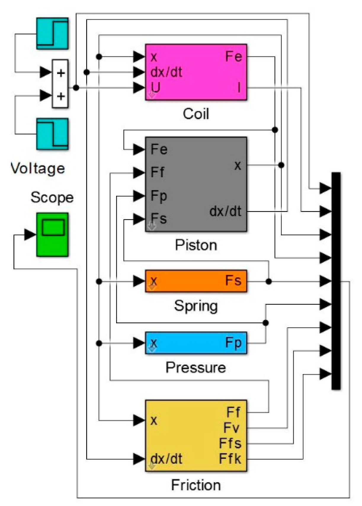
Presented as Equation (17), the system of differential equations was solved numerically with the implicit trapezoidal method combined with reverse differentiation (variable steps, min step 1 × 10⁻⁷ s). The maximum displacement of plunger xmax was taken as the control parameter in presented calculations. To achieve this goal, the limitations in the integration block of Simulink software were used, where each time an xmax value was set. The block diagram of the model implemented in the Matlab-Simulink environment is shown in Figure 5.
The first attempts were made to calibrate the model and to determine the correlation of the characteristic values obtained from the calculations with the manufacturer’s technical data. Basing on Equation (17) and the course of the pulse voltage U, it was possible to determine the course of current I, velocity, and as a result the plunger x displacement. Having the results of the calculations at xmax = 0.4 × 10⁻³ m (Figure 6) they were compared with the technical data of Valtek Rail Type-30 injector presented in Table 1.
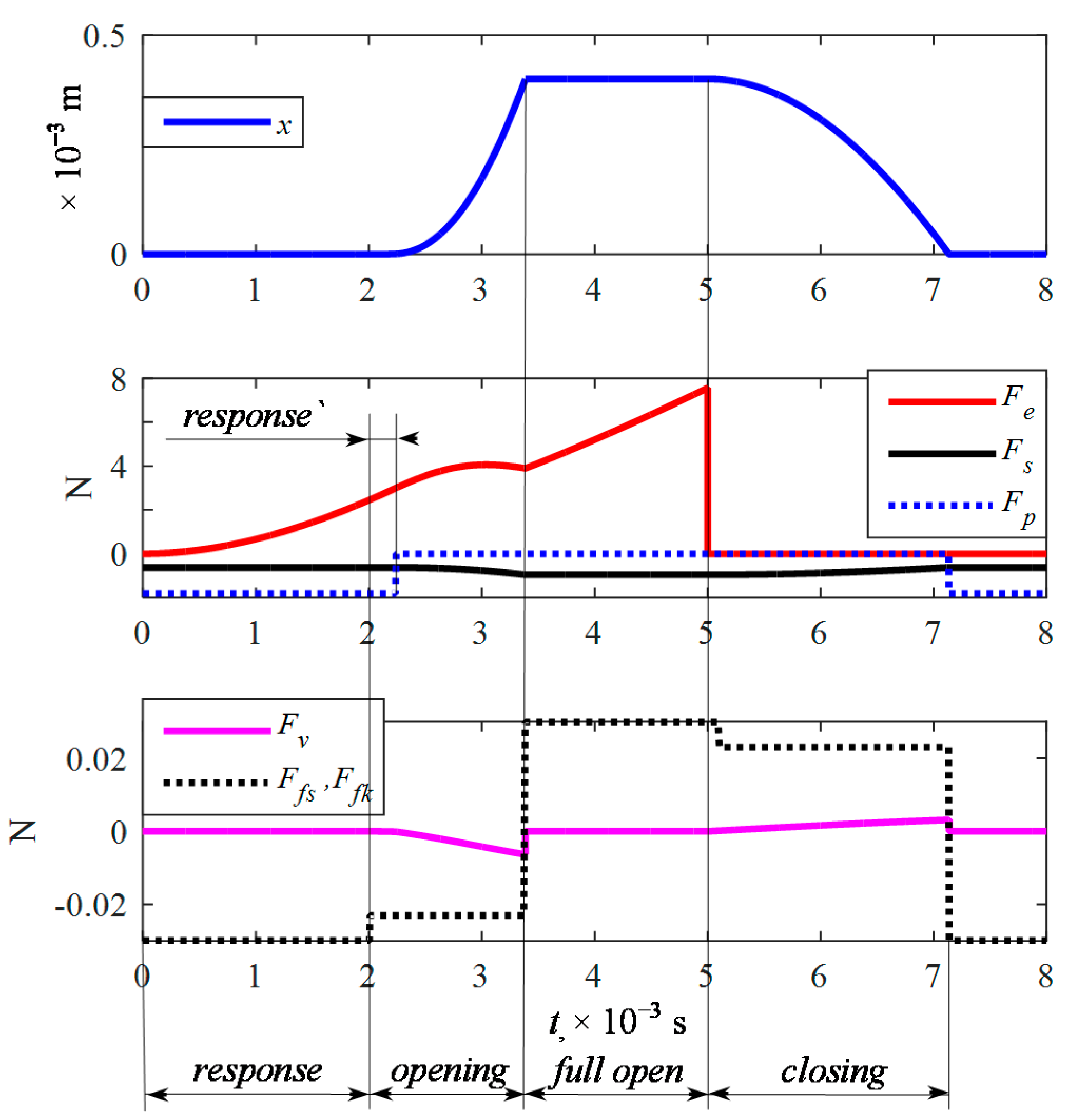
The opening time obtained from the calculations was to = 3.386 × 10⁻³ s compared to 3.4 × 10⁻³ s declared by the manufacturer. The closing time obtained from the calculation was tc = 2.138 × 10⁻³ s compared to 2.2 × 10⁻³ s as declared by the manufacturer. This gives a comparison of 0.4% and 2.8% difference, which was considered sufficient to perform a comparative analysis by calculation. The calculations also allowed for the analysis of the operating forces (Figure 7). As can be observed, the electromagnetic coil force Fe, the pressure force Fp, and the spring force Fs play a dominant role. Friction forces Ffs, Ffk, and Fv affect the plunger movement in a small manner (more than 10 times lower value), which means a small damping.
4. Impact of Plunger Stroke on Functional Parameters of the Injector
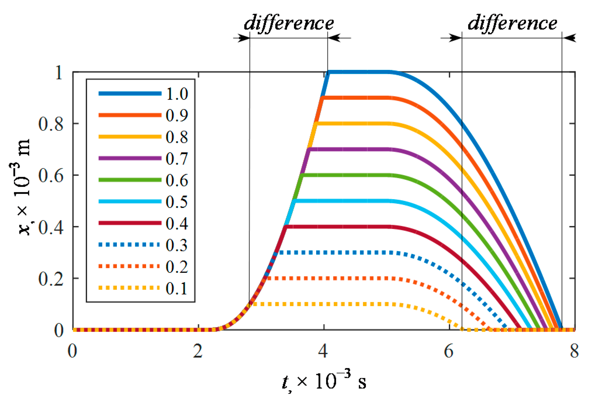
By using the mathematical model of the gas injector implemented in the Matlab-Simulink environment, its maximum elevation was regulated in the range of xmax = (0.1…1.0) × 10−3 m. The plunger displacement courses were analyzed (Figure 8).
Differences in functional parameters amounting to more than 1 ms on the opening and closing side of the injector were noted (Table 3).
Additionally, it was noted that the opening time is on average two-times longer than the closing time. This is an unfavorable phenomenon as it significantly distorts the extortion–response relationship. With comparable opening and closing times, this relationship exists and the opening response time indicates a time shift in the response. In some gas Electronic Control Unit (ECU) solutions the injector selection option appears, which allows the opening response time to be corrected. Times of opening and closing are essential in the process of adaptation of the engine from original (petrol) to alternative gas [24,26] In the case of some engines, petrol injectors operate at short, 5 × 10⁻³ s and less opening pulses.
It is then required that the gas injector can also open during this time. If we have a Valtek Rail Type-30 injector, which has a very large opening response time and a total opening time of 3.4 × 10⁻³ s, it means that the minimum value of the injection time is tinj = 3.4 × 10⁻³ s with factory settings xmax = 0.4 × 10⁻³ mm. Therefore it is possible to try to reduce xmax, which will allow to achieve a reduction of the minimum injection time, at which the injector will open. This must be confronted with an increase in outlet nozzle diameter or an increase in gas pressure. However, an increase in gas pressure, as shown in the calculation, has a significant effect on the opening time. The situation is even worse in the case of so-called “fuel injections”. When the engine load is rapidly increased, the control algorithm enriches the flammable mixture with extended injection time, or worse for the gas system, injects fuel several times, at very short times. It is found that short times that may be out of the range of full opening of the gas injector. This results in the engine ECU collecting information about the flammable mixture imbalance, resulting in a check engine.
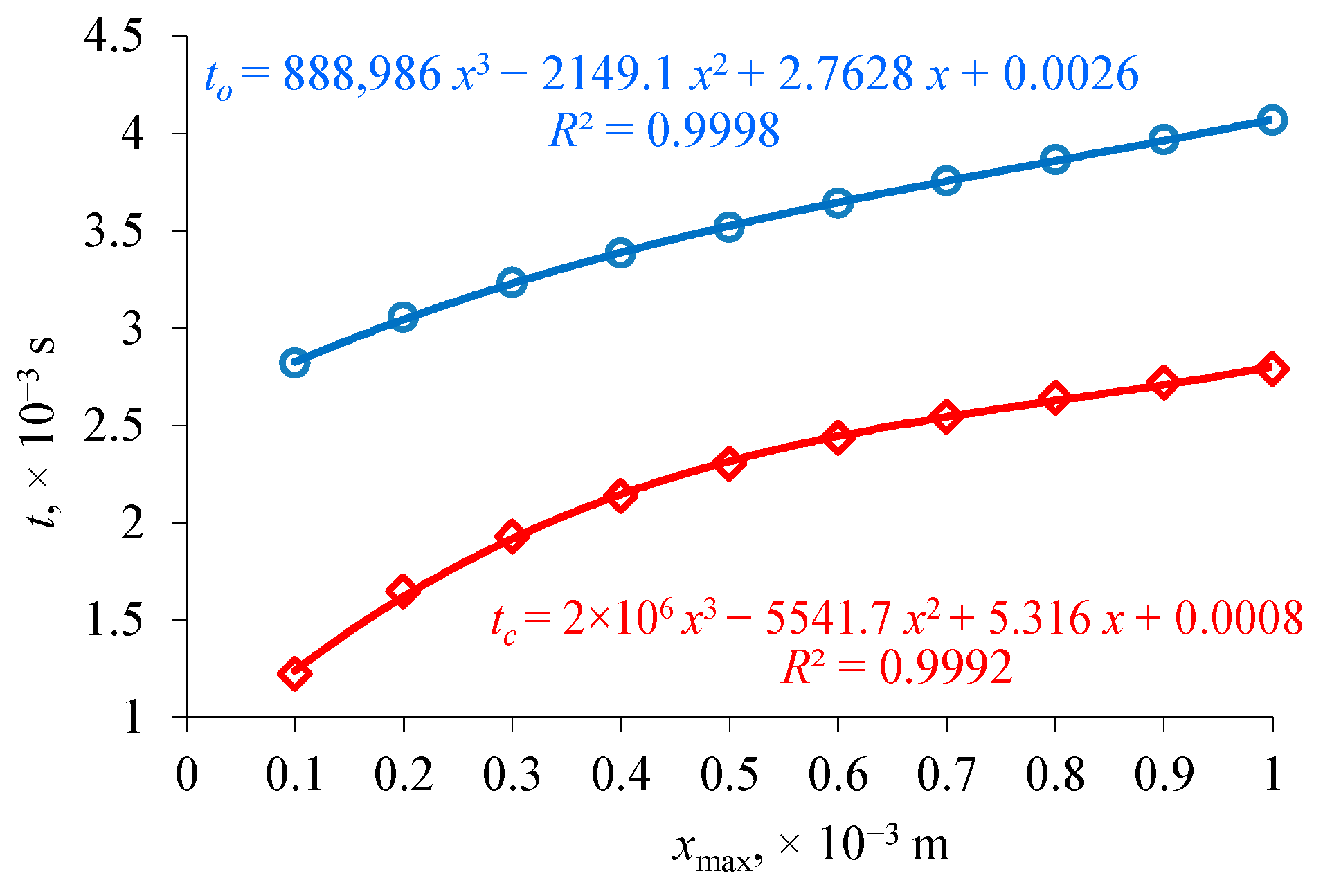
The purpose of the study was to evaluate the impact of plunger xmax stroke on functional parameters limited to opening to and closing time tc. As a result of the calculations performed, functional dependencies describing the variability of opening and closing times at different plunger strokes were determined. The characteristic values of the times were approximated by polynomials of the third degree (Figure 9) and obtained with determination factor R2 > 99.9%.
This confirmed the applicability of the mathematical model proposed in the study. Additionally, it was shown that the opening and closing times change by different values as the plunger stroke increases. This is an additional factor influencing the distortion of the force–response relation and consequently, the amount of fuel dose. During the use of the injector, its stroke may change under the influence of emerging contaminants (decrease) or as a result of wear of plunger damping elements (increase).
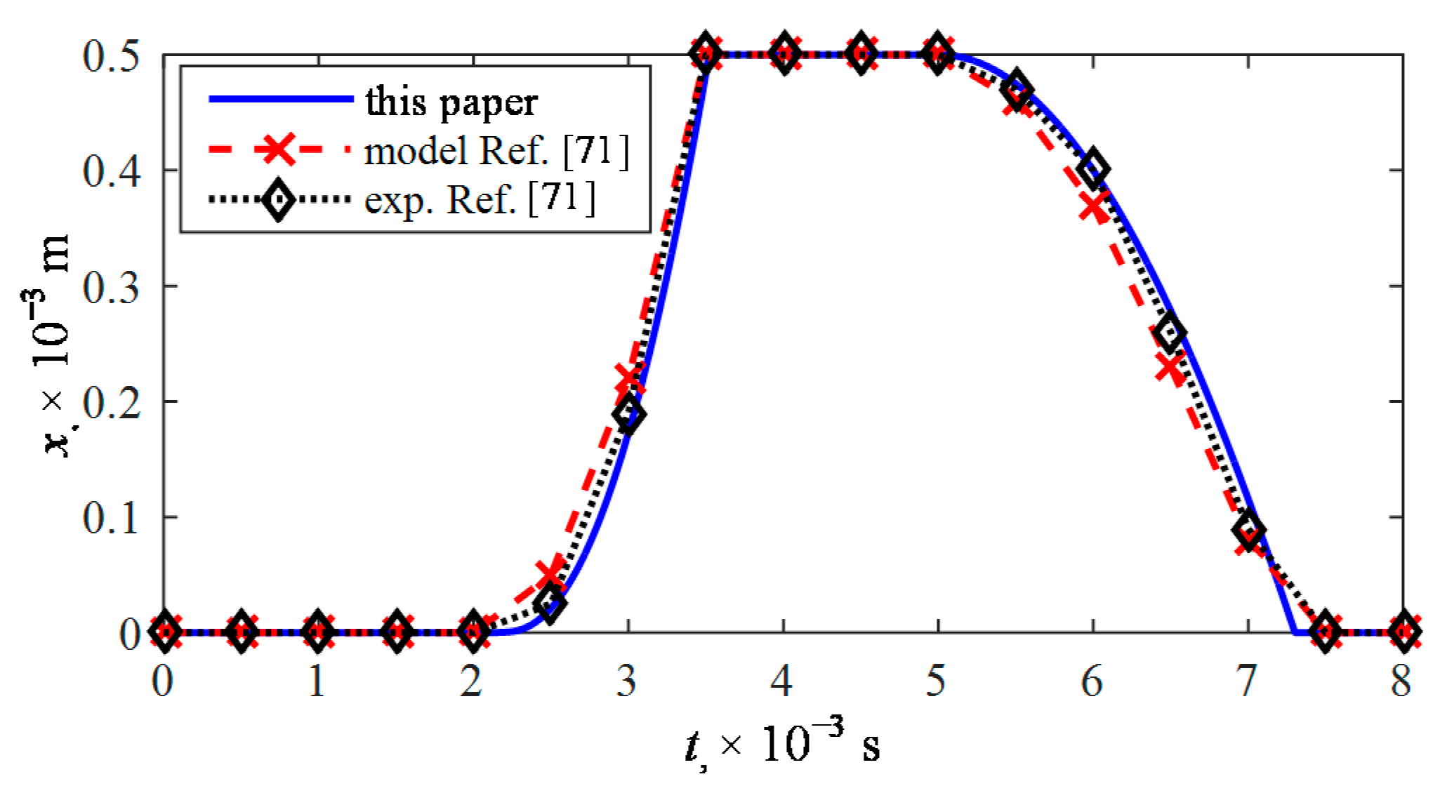
In the final stage of the study, to verify the correctness of the mathematical description adopted in this paper and the way of obtaining the results, the course of the plunger lift with the value xmax = 0.5 × 10⁻³ m was compared with the results presented in [71]. The compliance of calculation courses mentioned in the paper [71] and the innovative model proposed in this paper (Figure 10) have been noted. At the same time, it was found that the presented model shows changes of plunger displacement more accurately and is more comparable to the results of experimental studies from the paper [71].
It was found that there were no calculation results in the published reports or experimental studies concerning the impact of plunger stroke on functional parameters of the injector. Therefore, in order to additionally verify the correctness of the applied mathematical model, the characteristic opening and closing times of the Valtek Rail Type-30 injector were compared to those available in only a few studies. The calculation and test results presented in Table 4 were compared each time to those declared by the manufacturer where the nominal stroke should be 0.5 × 10⁻³ m.
By comparing the results of calculations presented in this study with those available in the literature, we can see a more correct description of the electromagnetic drive which affects the process of opening the injector. Therefore, it is the mathematical model of a circuit with an electromagnetic coil that is the essence of this paper. The problem when referring to experimental results is the lack of confirmation from the authors of stroke control of the actuator before the measurement. This is essential because, as simulation studies have shown, this determines the opening and closing times. Only the method using high speed camera [72] can be considered as direct. However, the lack of confirmation of the plunger stroke value of the brand new injector and the fact that an additional element was attached to the plunger, which changes its mass, may result in a change in opening and closing times. Overall, using this method, there were differences of about (3 and 14%). In addition, the low number of measurement points, which has already been mentioned before, precludes detailed analysis. The measurement methods presented in [26,72] can be qualified as indirect, where as shown in Table 4, the differences in values are quite high, reaching 54%.
The lack of possibility for direct comparison of model courses presented in this paper with the results of other authors resulted in planning our own future experimental tests regarding the impact of the plunger stroke on the functional parameters of the injector. Two options are being considered. Firstly, the use of a non-contact optical sensor, which requires interference with the injector body (cutting out its parts), which may change the inductance of the electromagnetic circuit to some degree, but will not load the plunger. The second variant is to use an inductive sensor and a needle fixed to the plunger. In this case, it is also expected that the circuit inductance and additionally the weight of the plunger will change. Only then will it be possible to confirm the correctness of the mathematical model presented in this paper.
5. Summary and Conclusions
The analysis presented in the paper aimed at estimating the opening and closing time of a variable stroke low-pressure gas injector. For this purpose, an in-house developed physics-based, control-oriented injector model was implemented in a Matlab-Simulink simulation. The conclusions are as follows:
- The presented new mathematical model was successfully validated. The simulated opening and closing times differed respectively, by 0.4% and 2.8% from the declaration in the injector technical documentation.
- The proposed mathematical description of the reluctance of the coil and its inductance are the basis of the modular model architecture. Further modifications can be introduced to this submodel, for improved simulation accuracy, by accounting for the reluctance of the electromagnetic circuit components and their location.
- The plunger forces’ analysis showed the dominant role of electromagnetic coil force, pressure, and the spring force. On the other hand, the forces responsible for frictional damping are of an order of magnitude lower.
- As the plunger stroke increases, the asymmetry of the opening time/closing time direct influence is noticeable, which may affect the amount of fuel dosing.
- A comparison of the results with the calculations of other authors has shown compatibility. The proposed model is more responsive to the variability of forces and movement conditions.
- The innovative concept of coil inductance modeling, incorporating the core dynamics, proposed in this paper is correct, was found to be valid within the constraints of the adopted literature reference data.
The obtained functional relations for opening and closing times as the plunger stroke increases can be used in the mathematical modeling of the operation of the internal combustion engine or during the calibration of the gas supply system under real conditions. The presented mathematical model of the gas injector can be successfully used to assess the influence of factors other than the presented ones, such as supply voltage, system pressure, or plunger mass on functional parameters. In the next research stage, the new model will be validated against real-world injector operational data.
Author Contributions
D.S. developed the concept of the manuscript, supervised all analyses and writing of the manuscript, developed the mathematical model and its solutions, and wrote the paper. M.K. contributed to the mathematical modeling, compared the obtained results with the ones from the literature, reviewed and edited the article. All authors have read and agreed to the published version of the manuscript.
Funding
This publication was financed through the program of the Ministry of Science and Higher Education of Poland named “Regional Initiative of Excellence” in 2019–2022 project number 011/RID/2018/19.
Acknowledgments
This research was founded through subsidy of the Ministry of Science and Higher Education of Poland for the discipline of mechanical engineering at the Faculty of Mechanical Engineering Bialystok University of Technology WZ/WM-IIM/4/2020.
Conflicts of Interest
The authors declare no conflict of interest.
Abbreviations and Acronyms
The following abbreviations and acronyms are used in this manuscript:
| EFA | Example of First Abbreviation |
| AMFA | Alternative Motor Fuels Act |
| CAFÉ | Corporate Average Fuel Economy |
| CAI | Controlled Auto-Ignition |
| CFD | Computational Fluid Dynamics |
| CNG | Compressed Natural Gas |
| CO2 | Carbon dioxide |
| ECU | Electronic Control Unit |
| FEM | Finite Element Method |
| HCCI | Homogeneous Charge Compression Ignition |
| HPDI | High Pressure Direct Injection |
| LPG | Liquefied Petroleum Gas |
| PWM | Pulse-Width Modulation signal |
| RCCI | Reactivity Controlled Compression Ignition |
| RDE | Real Driving Emissions test |
| WLTC | Worldwide harmonized Light vehicles Test Cycle |
| A1 | cross area over the plunger, m2 |
| A2 | cross area under the plunger, m2 |
| ac | distance of the plunger center of mass from the edge of the coil, m |
| dc | internal diameter of the coil, m |
| Dc | outer diameter of the coil, m |
| Fe | electromagnetic force, N |
| Ff | friction force, N |
| Ffk | kinetic friction force, N |
| Ffs | static friction force, N |
| Ffv | viscous friction force, N |
| Fm | resistance force of mass inertial, N |
| FN | normal force, N |
| Fp | pressure force, N |
| Fs | spring force, N |
| g | gravitational acceleration, m⋅s−2 |
| ga | air gap between the plunger and the inner edge of the coil, m |
| Hc | coil length, m |
| hc | length of plunger outside the valve cabinet, m |
| I | current, A |
| k | spring stiffness, N⋅m−1 |
| L | inductance, H |
| m | plunger mass, kg |
| Nc | number of turns of coil, - |
| p1 | gas pressure, Pa |
| p2 | inlet manifold pressure, Pa |
| R | resistance, Ω |
| RM | magnetic reluctance, H−1 |
| tc | closing time, s |
| tinj | injection time, s |
| to | opening time, s |
| U | voltage, V |
| x | plunger displacement, m |
| x0 | initial tension the spring, m |
| Δto | opening time difference, % |
| Δtc | closing time difference, % |
| μ0 | permeability of vacuum, H⋅m−1 |
| μk | coefficient of coefficient of kinetic friction, - |
| μs | coefficient of static friction, - |
| μv | coefficient of coefficient of viscous friction, N⋅s⋅m−1 |
References
- Streimikiene, D.; Baležentis, T.; Baležentiene, L. Comparative assessment of road transport technologies. Renew. Sustain. Energy Rev. 2013, 20, 611–618. [Google Scholar] [CrossRef]
- Raslavičius, L.; Keršys, A.; Mockus, S.; Keršiene, N.; Starevičius, M. Liquefied petroleum gas (LPG) as a medium-term option in the transition to sustainable fuels and transport. Renew. Sustain. Energy Rev. 2014, 32, 513–525. [Google Scholar] [CrossRef]
- Gül, T.; Kypreos, S.; Turton, H.; Barreto, L. An energy-economic scenario analysis of alternative fuels for personal transport using the Global Multi-regional MARKAL model (GMM). Energy 2009, 34, 1423–1437. [Google Scholar] [CrossRef]
- Liu, Y.; Helfand, G.E. The Alternative Motor Fuels Act, alternative-fuel vehicles, and greenhouse gas emissions. Transp. Res. Part A Policy Pract. 2009, 43, 755–764. [Google Scholar] [CrossRef]
- Council of the European Union. Council Directive 2014/94/EU of 22 October 2014 on the Deployment of Alternative Fuels Infrastructure. Official Journal of the European Union, 28 October 2014; L 307/1. [Google Scholar]
- Leduc, P.; Dubar, B.; Ranini, A.; Monnier, G. Downsizing of gasoline engine: An efficient way to reduce CO2 emissions. Oil Gas. Sci. Technol. 2003, 58, 115–127. [Google Scholar] [CrossRef]
- Jeuland, N.; Montagne, X.; Duret, P. New HCCI/CAI combustion process development: Methodology for determination of relevant fuel parameters. Oil Gas. Sci. Technol. 2004, 59, 571–579. [Google Scholar] [CrossRef]
- Haraldsson, G. Closed-Loop Combustion Control of a Multi Cylinder HCCI Engine Using Variable Compression Ratio and Fast Thermal Management; Division of Combustion Engines, Lund Institute of Technology: Lund, Sweden, 2005. [Google Scholar]
- Mikulski, M.; Balakrishnan, P.R.; Doosje, E.; Bekdemir, C. Variable Valve Actuation Strategies for Better Efficiency Load Range and Thermal Management in an RCCI Engine. SAE Tech. Pap. 2018, 2018. [Google Scholar] [CrossRef]
- Mitukiewicz, G.; Dychto, R.; Leyko, J. Relationship between LPG fuel and gasoline injection duration for gasoline direct injection engines. Fuel 2015, 153, 526–534. [Google Scholar] [CrossRef]
- Mustafa, K.F.; Gitano-Briggs, H.W. Liquefied petroleum gas (LPG) as an alternative fuel in spark ignition engine: Performance and emission characteristics. In Proceedings of the ICEE 2009—Proceeding 2009 3rd International Conference on Energy and Environment: Advancement Towards Global Sustainability, Malacca, Malaysia, 7–8 December 2009. [Google Scholar]
- Ristovski, Z.D.; Jayaratne, E.R.; Morawska, L.; Ayoko, G.A.; Lim, M. Particle and carbon dioxide emissions from passenger vehicles operating on unleaded petrol and LPG fuel. Sci. Total Environ. 2005, 345, 93–98. [Google Scholar] [CrossRef] [Green Version]
- Bielaczyc, P.; Woodburn, J. Trends in Automotive Emission Legislation: Impact on LD Engine Development, Fuels, Lubricants and Test Methods: A Global View, with a Focus on WLTP and RDE Regulations. Emiss. Control. Sci. Technol. 2019, 5, 86–98. [Google Scholar] [CrossRef] [Green Version]
- Waluś, K.J.; Warguła, Ł.; Krawiec, P.; Adamiec, J.M. Legal regulations of restrictions of air pollution made by non-road mobile machinery—The case study for Europe: A review. Environ. Sci. Pollut. Res. 2018, 25, 3243–3259. [Google Scholar] [CrossRef] [PubMed] [Green Version]
- Warguła, Ł.; Krawiec, P.; Waluś, K.J.; Kukla, M. Fuel Consumption Test Results for a Self-Adaptive, Maintenance-Free Wood Chipper Drive Control System. Appl. Sci. 2020, 10, 2727. [Google Scholar] [CrossRef] [Green Version]
- Kalligeros, S.; Zannikos, F.; Stournas, S.; Lois, E.; Anastopoulos, G.; Karonis, D. Impact of gasoline quality on engine performance and emissions. In Proceedings of the 8th International Conference on Environmental Science and Technology, Lemnos Island, Greece, 8–10 September 2003; pp. 340–345. [Google Scholar]
- Anandarajah, G.; McDowall, W.; Ekins, P. Decarbonising road transport with hydrogen and electricity: Long term global technology learning scenarios. Int. J. Hydrogen Energy 2013, 38, 3419–3432. [Google Scholar] [CrossRef]
- Grigor’ev, M.A.; Naumovich, N.I.; Belousov, E.V. A traction electric drive for electric cars. Russ. Electr. Eng. 2015, 86, 731–734. [Google Scholar] [CrossRef]
- Marčič, S.; Marčič, M.; Praunseis, Z. Mathematical model for the injector of a common rail fuel-injection system. Engineering 2015, 7, 307–321. [Google Scholar] [CrossRef] [Green Version]
- Raslavičius, L.; Azzopardi, B.; Keršys, A.; Starevičius, M.; Bazaras, Ž.; Makaras, R. Electric vehicles challenges and opportunities: Lithuanian review. Renew. Sustain. Energy Rev. 2015, 42, 786–800. [Google Scholar] [CrossRef]
- Raslavičius, L.; Keršys, A.; Makaras, R. Management of hybrid powertrain dynamics and energy consumption for 2WD, 4WD, and HMMWV vehicles. Renew. Sustain. Energy Rev. 2017, 68, 380–396. [Google Scholar] [CrossRef]
- Dimitrova, Z.; Maréchal, F. Gasoline hybrid pneumatic engine for efficient vehicle powertrain hybridization. Appl. Energy 2015, 151, 168–177. [Google Scholar] [CrossRef]
- AC STAG 500 DIS. Available online: https://www.ac.com.pl (accessed on 2 February 2020).
- Borawski, A. Modification of a fourth generation LPG installation improving the power supply to a spark ignition engine. Eksploat. I Niezawodn. 2015, 17, 1–6. [Google Scholar] [CrossRef]
- Wendeker, M.; Jakliński, P.; Czarnigowski, J.; Boulet, P.; Breaban, F. Operational Parameters of Lpg Fueled Si Engine—Comparison of Simultaneous and Sequential Port Injection; Technical Report; SAE International: Warrendale, PA, USA, January 2007. [Google Scholar] [CrossRef]
- Czarnigowski, J. Teoretyczno-Empiryczne Studium Modelowania Impulsowego Wtryskiwacza Gazu; Wydawnictwo Politechniki Lubelskiej: Lublin, Poland, 2012; ISBN PL 978-83-63569-09-9. [Google Scholar]
- Szpica, D.; Czaban, J. Operational assessment of selected gasoline and LPG vapour injector dosage regularity. Mechanika 2014, 20, 480–488. [Google Scholar] [CrossRef] [Green Version]
- Szpica, D. Investigating fuel dosage non-repeatability of low-pressure gas-phase injectors. Flow Meas. Instrum. 2018, 59, 147–156. [Google Scholar] [CrossRef]
- Mieczkowski, G. Static electromechanical characteristics of piezoelectric converters with various thickness and length of piezoelectric layers. Acta Mech. Autom. 2019, 13, 30–36. [Google Scholar] [CrossRef] [Green Version]
- Mieczkowski, G.; Borawski, A.; Szpica, D. Static electromechanical characteristic of a three-layer circular piezoelectric transducer. Sensors 2020, 20, 222. [Google Scholar] [CrossRef] [PubMed] [Green Version]
- Li, M.H.; Jiang, F. Simulation research on fuel injection system of 16v265H diesel engine introduced from U.S. In Proceedings of the 2010 International Conference on E-Product E-Service and E-Entertainment, Henan, China, 7–9 November 2010. [Google Scholar]
- Yu, H.; Qian, X. RETRACTED ARTICLE: The calculation of main parameters of the gasoline engine fuel injection system. In Proceedings of the ICCASM 2010–2010 International Conference on Computer Application and System Modeling, Taiyuan, China, 22–24 October 2010. [Google Scholar]
- Mieczkowski, G.; Molski, K.; Seweryn, A. Finite-element modeling of stresses and displacements near the tips of pointed inclusions. Mater. Sci. 2007, 43, 183–194. [Google Scholar] [CrossRef]
- Marczuk, A.; Caban, J.; Aleshkin, A.V.; Savinykh, P.A.; Isupov, A.Y.; Ivanov, I.I. Modeling and simulation of particle motion in the operation area of a centrifugal rotary chopper machine. Sustainability 2019, 11, 4873. [Google Scholar] [CrossRef] [Green Version]
- Brumercik, F.; Lukac, M.; Caban, J.; Krzysiak, Z.; Glowacz, A. Comparison of selected parameters of a planetary gearbox with involute and convex-concave teeth flank profiles. Appl. Sci. 2020, 10, 1417. [Google Scholar] [CrossRef] [Green Version]
- Mehlfeldt, D.; Weckenmann, H.; Stöhr, G. Modeling of piezoelectrically actuated fuel injectors. Mechatronics 2008, 18, 264–272. [Google Scholar] [CrossRef]
- Yang, L.-J.; Fu, Q.-F.; Qu, Y.-Y.; Zhang, W.; Du, M.-L.; Xu, B.-R. Spray characteristics of gelled propellants in swirl injectors. Fuel 2012, 97, 253–261. [Google Scholar] [CrossRef]
- Borawski, A. Simulation studies of LPG injector used in 4th generation installations. Combust. Engines 2015, 160, 49–55. [Google Scholar]
- Bensetti, M.; Le Bihan, Y.; Marchand, C. Development of an hybrid 3D FEM for the modeling of micro-coil sensors and actuators. Sens. Actuators A Phys. 2006, 129, 207–211. [Google Scholar] [CrossRef]
- Cheng, Q.; Zhang, Z.D.; Guo, H.; Xie, N.L. Simulation and analysis on electro-magneticthermal coupling of solenoid GDI injector. Int. J. Appl. Electromagn. Mech. 2014. [Google Scholar] [CrossRef]
- Pacurar, C.; Topa, V.; Munteanu, C.; Racasan, A.; Hebedean, C.; Oglejan, R.; Vlad, G. Solenoid Actuator Parametric Analysis and Numerical Modeling. Acta Electroteh. 2015, 56, 246–251. [Google Scholar]
- Bali, E.; Erzan Topcu, E. Design on-off type solenoid valve for electropneumatic brake system and investigation of its static characteristics. Int. J. Adv. Automot. Technol. 2018, 2, 175–184. [Google Scholar] [CrossRef]
- Wendeker, M.; Jakliński, P.; Grabowski, Ł.; Pietrykowski, K.; Czarnigowski, J.; Hunicz, J. Model of CNG flap valve injector for internal combustion engines. Combust. Engines 2007, 131, 42–52. [Google Scholar]
- Czarnigowski, J.; Jakliński, P.; Wendeker, M.; Pietrykowski, K.; Grabowski, Ł. The analyses of the phenomena inside a CNG flap-valve injector during gas flow. Combust. Engines 2009, 136, 10–18. [Google Scholar]
- Szpica, D. Simplified numerical simulation as the base for throttle flow characteristics designation. Mechanika 2015, 21, 129–133. [Google Scholar] [CrossRef] [Green Version]
- Hung, N.B.; Lim, O. Improvement of Electromagnetic Force and Dynamic Response of a Solenoid Injector Based on the Effects of Key Parameters. Int. J. Automot. Technol. 2019. [Google Scholar] [CrossRef]
- Taghizadeh, M.; Ghaffari, A.; Najafi, F. Modeling and identification of a solenoid valve for PWM control applications. Comptes Rendus Mec. 2009, 337, 131–140. [Google Scholar] [CrossRef]
- Szpica, D. Modeling of current limitation through the PWM signal in LPG injectors. In Proceedings of the Transport Means—Proceedings of the International Conference, Juodkrante, Lithuania, 5–7 October 2016; pp. 536–539. [Google Scholar]
- Xiang, Z.; Liu, H.; Tao, G.L.; Man, J.; Zhong, W. Development of an ε-type actuator for enhancing high-speed electro-pneumatic ejector valve performance. J. Zhejiang Univ. Sci. A 2008. [Google Scholar] [CrossRef]
- Lu, F.K.; Jensen, D.S. Potential viability of a fast-acting micro-solenoid valve for pulsed detonation fuel injection. In Proceedings of the 41st Aerospace Sciences Meeting and Exhibit, Reno, Nevada, 6–9 January 2003. [Google Scholar]
- Dongiovanni, C.; Dongiovanni, C.; Coppo, M. Accurate Modelling of an Injector for Common Rail Systems. In Fuel Injection; Siano, D., Ed.; IntechOpen: Rijeka, Croatia, 2010; pp. 95–119. [Google Scholar] [CrossRef] [Green Version]
- Cheng, Q.; Zhang, Z.D.; Guo, H.; Xie, N.L. Electro-magnetic-thermal coupling of GDI injector. Jilin Daxue Xuebao J. Jilin Univ. 2015. [Google Scholar] [CrossRef]
- Plavec, E.; Ladisic, I.; Vidovic, M. The impact of coil winding angle on the force of DC solenoid electromagnetic actuator. Adv. Electr. Electron. Eng. 2019, 17, 244–250. [Google Scholar] [CrossRef]
- Liu, Y.F.; Dai, Z.K.; Xu, X.I.; Tian, L. Multi-domain modeling and simulation of proportional solenoid valve. J. Cent. South. Univ. Technol. 2011. [Google Scholar] [CrossRef]
- Tian, H.; Zhao, Y. Coil inductance model based solenoid on/off valve spool displacement sensing via laser calibration. Sensors 2018, 18, 4492. [Google Scholar] [CrossRef] [PubMed] [Green Version]
- Li, P.X.; Su, M.; Zhang, D.B. Response characteristic of high-speed on/off valve with double voltage driving circuit. IOP Conf. Ser. Mater. Sci. Eng. 2017, 220, 012028. [Google Scholar] [CrossRef] [Green Version]
- Cvetkovic, D.; Cosic, I.; Subic, A. Improved performance of the electromagnetic fuel injector solenoid actuator using a modelling approach. Int. J. Appl. Electromagn. Mech. 2008, 27, 251–273. [Google Scholar] [CrossRef]
- Lunge, S.P.; Kurode, S.; Chhibber, B. Proportional actuator from on off solenoid valve using sliding modes. In Proceedings of the 1st International and 16th National Conference on Machines and Mechanisms, Uttarakhand, India, 18–20 December 2013; p. 76. [Google Scholar]
- Morselli, R.; Corti, E.; Rizzoni, G. Energy based model of a common rail injector. In Proceedings of the IEEE Conference on Control Applications, Glasgow, UK, 18–20 September 2002. [Google Scholar]
- Borawski, A. Common methods in analysing the tribological properties of brake pads and discs-A review. Acta Mech. Autom. 2019, 13, 189–199. [Google Scholar] [CrossRef] [Green Version]
- Li, T.E.; Sun, X.Y.; Wu, Y.; Wang, C.G. Parameter analysis of aerodynamic drag force in stratospheric airship. Gongcheng Lixue Eng. Mech. 2019. [Google Scholar] [CrossRef]
- Chernov, N.N.; Palii, A.V.; Saenko, A.V.; Maevskii, A.M. A Method of Body Shape Optimization for Decreasing the Aerodynamic Drag Force in Gas Flow. Tech. Phys. Lett. 2018. [Google Scholar] [CrossRef]
- Czarnigowski, J.; Wendeker, M.; Jakliński, P.; Rola, M.; Grabowski, Ł.; Pietrykowski, K. CFD Model of Fuel Rail for LPG Systems; Technical Report; SAE International: Warrendale, PA, USA, January 2007. [Google Scholar] [CrossRef]
- Chu, L.; Hou, Y.; Liu, M.; Li, J.; Gao, Y.; Ehsani, M. Study on the dynamic characteristics of pneumatic ABS solenoid valve for commercial vehicle. In Proceedings of the VPPC 2007—Proceedings of the 2007 IEEE Vehicle Power and Propulsion Conference, Arlington, TX, USA, 9–12 September 2007. [Google Scholar]
- Szpica, D.; Kusznier, M. Modelling of the low pressure gas injector operation. Acta Mech. Autom. 2020, 14, 29–35. [Google Scholar] [CrossRef]
- Czarnigowski, J.; Jakliński, P.; Zyska, T.; Duk, M. Model empiryczny prądu w obwodzie impulsowego wtryskiwacza gazu. Prz. Elektrotechniczny 2014. [Google Scholar] [CrossRef]
- Szpica, D. Validation of indirect methods used in the operational assessment of LPG vapor phase pulse injectors. Meas. J. Int. Meas. Confed. 2018, 118, 253–261. [Google Scholar] [CrossRef]
- Valtek Type 30—Technical Data. Available online: https://www.valtek.it (accessed on 2 February 2020).
- Passarini, L.C.; Pinotti, M. A new model for fast-acting electromagnetic fuel injector analysis and design. J. Brazilian Soc. Mech. Sci. Eng. 2003, 25, 95–106. [Google Scholar] [CrossRef]
- Passarini, L.C.; Nakajima, P.R. Development of a high-speed solenoid valve: An investigation of the importance of the armature mass on the dynamic response. J. Brazilian Soc. Mech. Sci. Eng. 2003, 25, 329–335. [Google Scholar] [CrossRef]
- Borawski, A. Analiza Procesu Zasilania Silników Spalinowych o Zapłonie Iskrowym Alternatywnym Układem LPG IV Generacji; Bialystok University of Technology: Bialystok, Porland, 2013. [Google Scholar]
- Szpica, D. Comparative analysis of the characteristics of a low-pressure gas-phase injector. Flow Meas. Instrum. 2017, 58, 74–86. [Google Scholar] [CrossRef]
Figure 1.
Valtek Rail Type-30 gas injector: 1—plunger; 2—corps; 3—spring; 4—coil; 5—cramp; 6—pilot; 7—limiter; 8—inlet nozzle; and 9—outlet nozzle.
Figure 1.
Valtek Rail Type-30 gas injector: 1—plunger; 2—corps; 3—spring; 4—coil; 5—cramp; 6—pilot; 7—limiter; 8—inlet nozzle; and 9—outlet nozzle.

Figure 2.
The scheme of the Valtek Rail Type-30 gas injector: Fe—electromagnetic force; Ff—frictional force; Fs—spring force; Fp—pressure force; Fm—resistance force of mass inertia; x—plunger displacement.
Figure 2.
The scheme of the Valtek Rail Type-30 gas injector: Fe—electromagnetic force; Ff—frictional force; Fs—spring force; Fp—pressure force; Fm—resistance force of mass inertia; x—plunger displacement.

Figure 3.
The generic scheme for calculating the inductance of the Valtek Rail Type-30 electromagnetic circuit: ac—distance of the plunger center of mass from the edge of the coil; dc—internal diameter of the coil; Dc—outer diameter of the coil; ga—air gap between the plunger and the inner edge of the coil; Hc—coil length; hc—length of plunger outside the valve cabinet.

Figure 4.
Calculated values of inductance and its derivative.

Figure 5.
The block diagram in the Matlab-Simulink.

Figure 6.
Variations of voltage, current in coil and plunger displacement were obtained by calculation at xmax = 0.4 × 10⁻³ m.
Figure 6.
Variations of voltage, current in coil and plunger displacement were obtained by calculation at xmax = 0.4 × 10⁻³ m.

Figure 7.
Variations of plunger displacement and acting forces were obtained by calculation at xmax = 0.4 × 10⁻³ m.
Figure 7.
Variations of plunger displacement and acting forces were obtained by calculation at xmax = 0.4 × 10⁻³ m.

Figure 8.
Calculated plunger displacement courses at different limit values xmax = (0.1…1.0) × 10−3 m.
Figure 8.
Calculated plunger displacement courses at different limit values xmax = (0.1…1.0) × 10−3 m.

Figure 9.
Relation of opening to and closing time tc to plunger stroke xmax.

Figure 10.
Calculation results verification.


Table 1.
The technical data of the Valtek Rail Type-30 injector. Data taken from Ref. [68].
Table 1.
The technical data of the Valtek Rail Type-30 injector. Data taken from Ref. [68].
| Parameter | Value |
|---|---|
| nozzle size | 4 × 10⁻³ m |
| piston stroke | 0.4 × 10⁻³ m |
| coil resistance | 3 Ω |
| opening time | 3.4 × 10⁻³ s |
| closing time | 2.2 × 10⁻³ s |
| maximum working pressure | 4.5 × 10³ Pa |
| operating temperature | (−20… + 120) + 273.15 K |
Table 2.
The parameters and function conditions needed to initiate the simulation.
| Parameter | Value |
|---|---|
| injection time | tinj = 5 × 10⁻³ s |
| mass of the piston and needle | m = 5 × 10⁻³ kg |
| resistance/impedance | R = 3 Ω |
| initial tension the spring | x0 = 0.75 × 10⁻³ m |
| coefficient of static friction | μs = 0.61 |
| coefficient of kinematic friction | μk = 0.47 |
| coefficient of viscous friction | μv = 0.009 N⋅s⋅m−1 |
| normal force | FN = m g |
| cross area over the valve | A1 = 32.56 × 10⁻⁶ m2 |
| cross area under the valve | A2 = 12.56 × 10⁻⁶ m2 |
| gas pressure | p1 = 1 × 10⁵ Pa + p2 |
| inlet manifold pressure | p2 = 1 × 10⁵ Pa |
| Boundary Conditions | |
| at t = 0 | U = 12 V; x = 0 m |
| after the time t = tinj, | U = 0 V |
Table 3.
The calculated values of opening to and closing time tc at different maximum heights (stroke) plunger.
Table 3.
The calculated values of opening to and closing time tc at different maximum heights (stroke) plunger.
| xmax, × 10−3 m | 0.1 | 0.2 | 0.3 | 0.4 | 0.5 | 0.6 | 0.7 | 0.8 | 0.9 | 1.0 |
|---|---|---|---|---|---|---|---|---|---|---|
| to, × 10−3 s | 2.82 | 3.05 | 3.23 | 3.39 | 3.52 | 3.64 | 3.76 | 3.87 | 3.97 | 4.07 |
| tc, × 10−3 s | 1.22 | 1.65 | 1.93 | 2.14 | 2.30 | 2.43 | 2.55 | 2.64 | 2.72 | 2.79 |
Table 4.
Comparison of Valtek Rail Type-30 injector opening and closing times.
| Source | Method | to, × 10−3 s | tc, × 10−3 s | Δto, % | Δtc, % |
|---|---|---|---|---|---|
| Ref. [68] | manufacturer | 3.40 | 2.20 | − | − |
| this paper | modeling | 3.386 | 2.138 | −0.41 | −2.82 |
| Ref. [65] | modeling | 3.47 | 2.15 | 2.05 | −2.27 |
| Ref. [71] | modeling | 3.50 | 2.50 | −2.94 | 13.64 |
| Ref. [26] | experiment (current line) | 3.30 | − | −2.94 | − |
| Ref. [71] | experiment (high speed camera) | 3.50 | 2.50 | 2.94 | 13.64 |
| Ref. [72] | experiment (1 pressure sensor) | 3.10 | 2.54 | −8.82 | 15.45 |
| Ref. [26] | experiment (2 pressure sensor) | − | 1 | − | −54.55 |
| Ref. [72] | experiment (vibration sensor) | 2.70 | 2.45 | −20.59 | 11.36 |
Publisher’s Note: MDPI stays neutral with regard to jurisdictional claims in published maps and institutional affiliations. |
© 2021 by the authors. Licensee MDPI, Basel, Switzerland. This article is an open access article distributed under the terms and conditions of the Creative Commons Attribution (CC BY) license (http://creativecommons.org/licenses/by/4.0/).
Share and Cite
MDPI and ACS Style
Szpica, D.; Kusznier, M. Model Evaluation of the Influence of the Plunger Stroke on Functional Parameters of the Low-Pressure Pulse Gas Solenoid Injector. Sensors 2021, 21, 234. https://0-doi-org.brum.beds.ac.uk/10.3390/s21010234
AMA Style
Szpica D, Kusznier M. Model Evaluation of the Influence of the Plunger Stroke on Functional Parameters of the Low-Pressure Pulse Gas Solenoid Injector. Sensors. 2021; 21(1):234. https://0-doi-org.brum.beds.ac.uk/10.3390/s21010234
Chicago/Turabian StyleSzpica, Dariusz, and Michał Kusznier. 2021. "Model Evaluation of the Influence of the Plunger Stroke on Functional Parameters of the Low-Pressure Pulse Gas Solenoid Injector" Sensors 21, no. 1: 234. https://0-doi-org.brum.beds.ac.uk/10.3390/s21010234
Note that from the first issue of 2016, this journal uses article numbers instead of page numbers. See further details here.