
False Ceiling Deterioration Detection and Mapping Using a Deep Learning Framework and the Teleoperated Reconfigurable ‘Falcon’ Robot

 ,
,  ,
,  ,
,
Abstract
:1. Introduction
2. Related Work
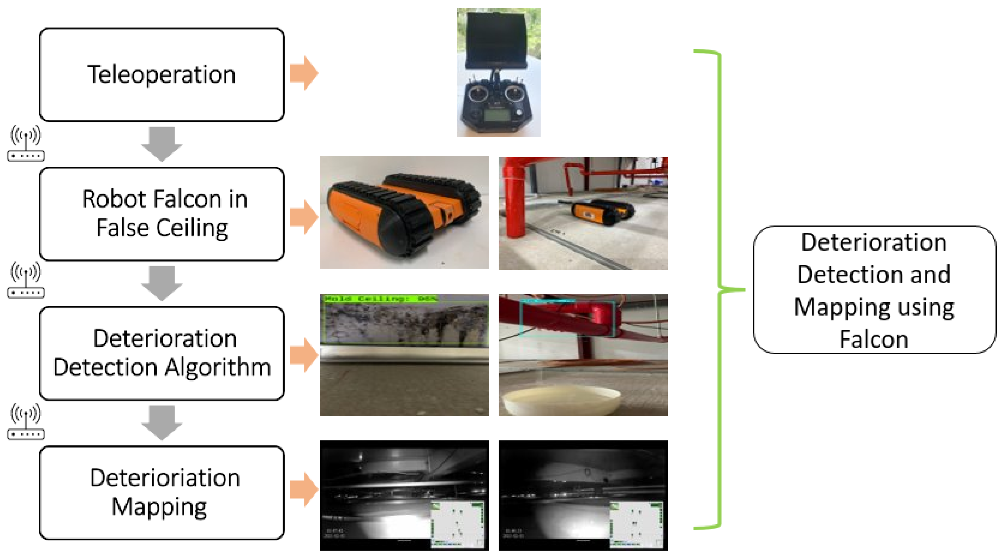
3. Overview of the Proposed System
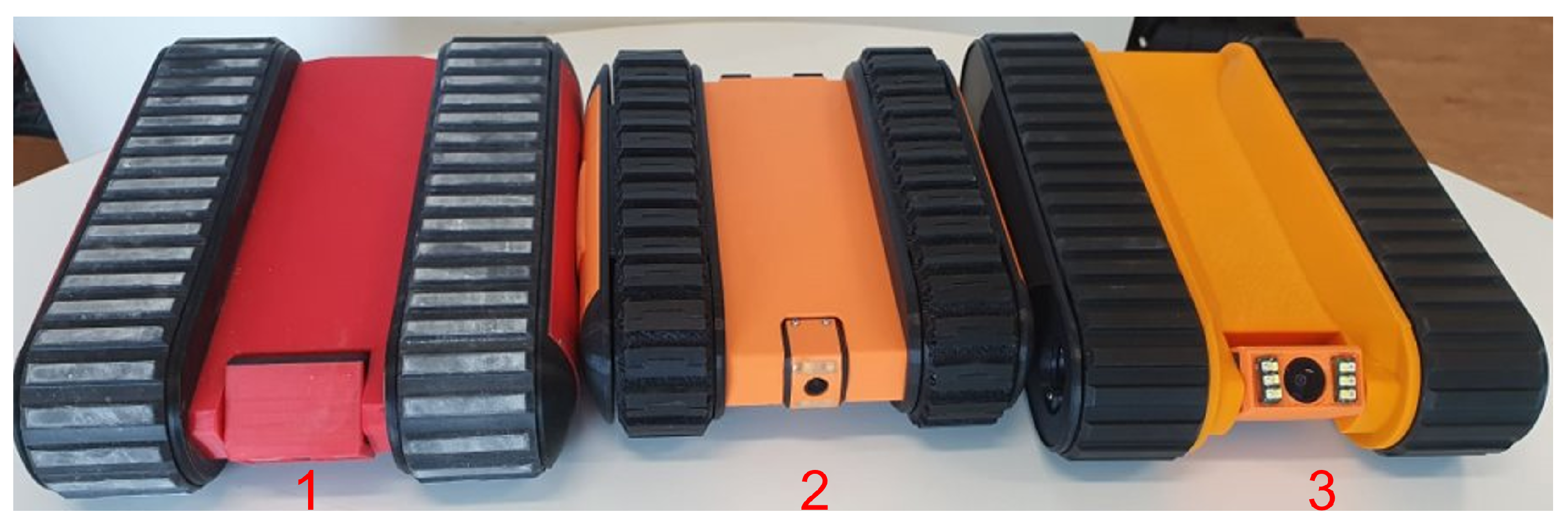
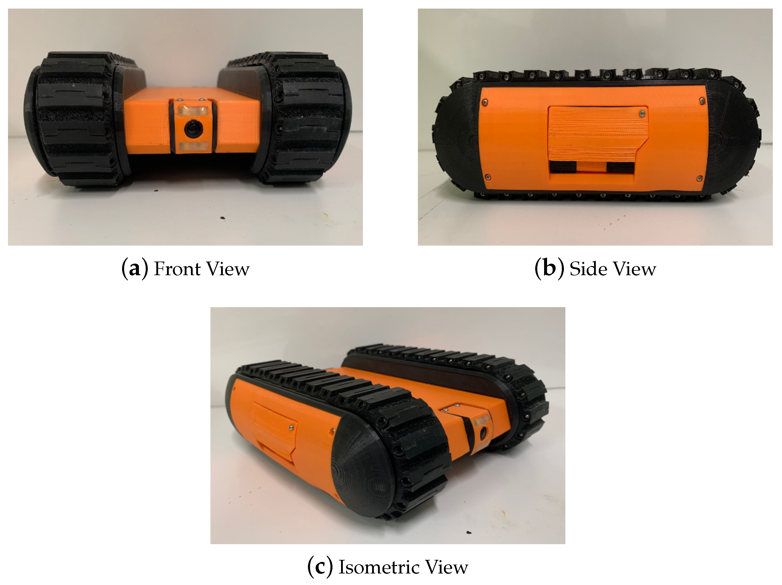
3.1. The Falcon Robot
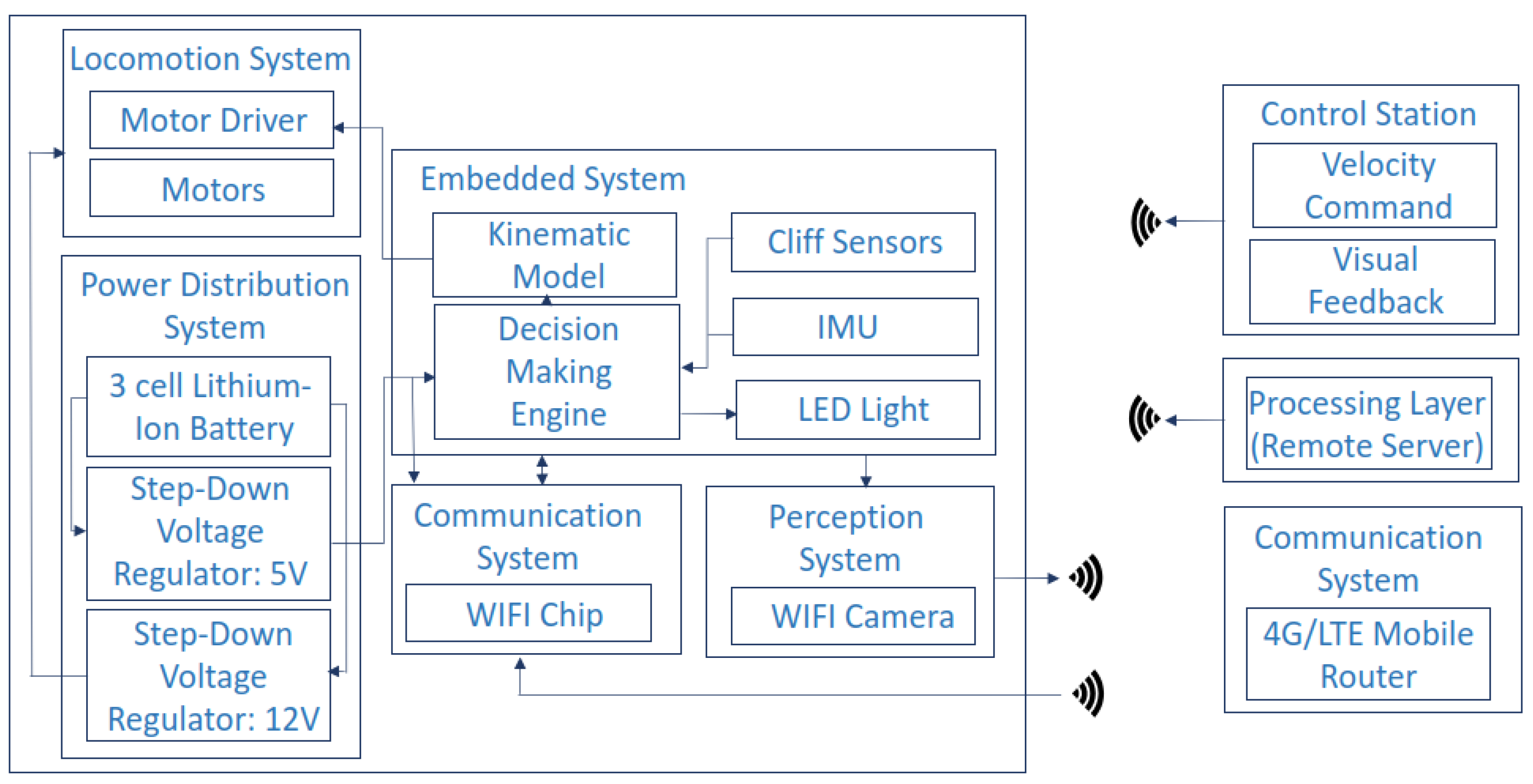
System Architecture
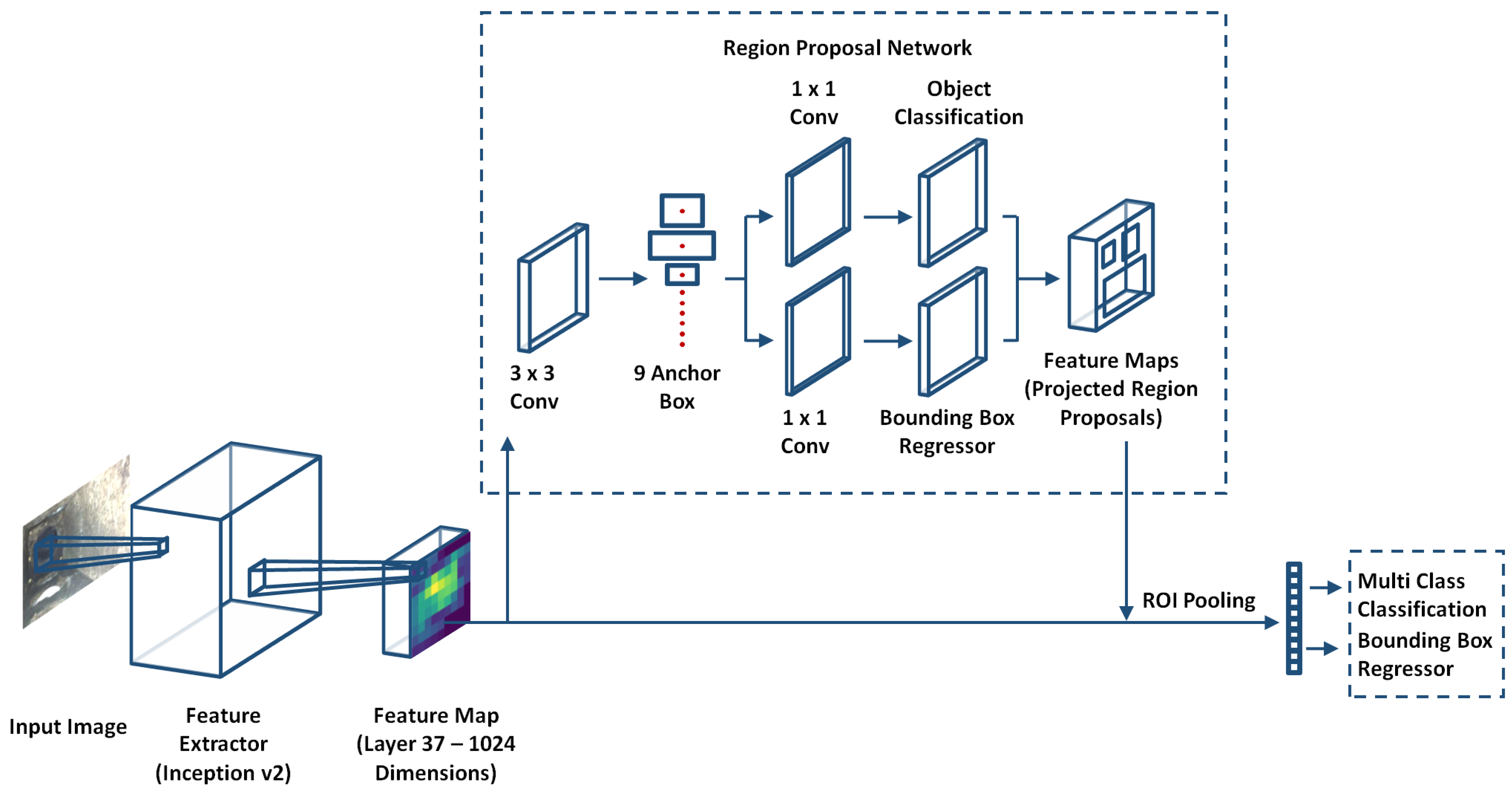
3.2. Deterioration Detection Algorithm
3.2.1. Feature Extractor Network
3.2.2. Region Proposal Network
3.2.3. Detection Network
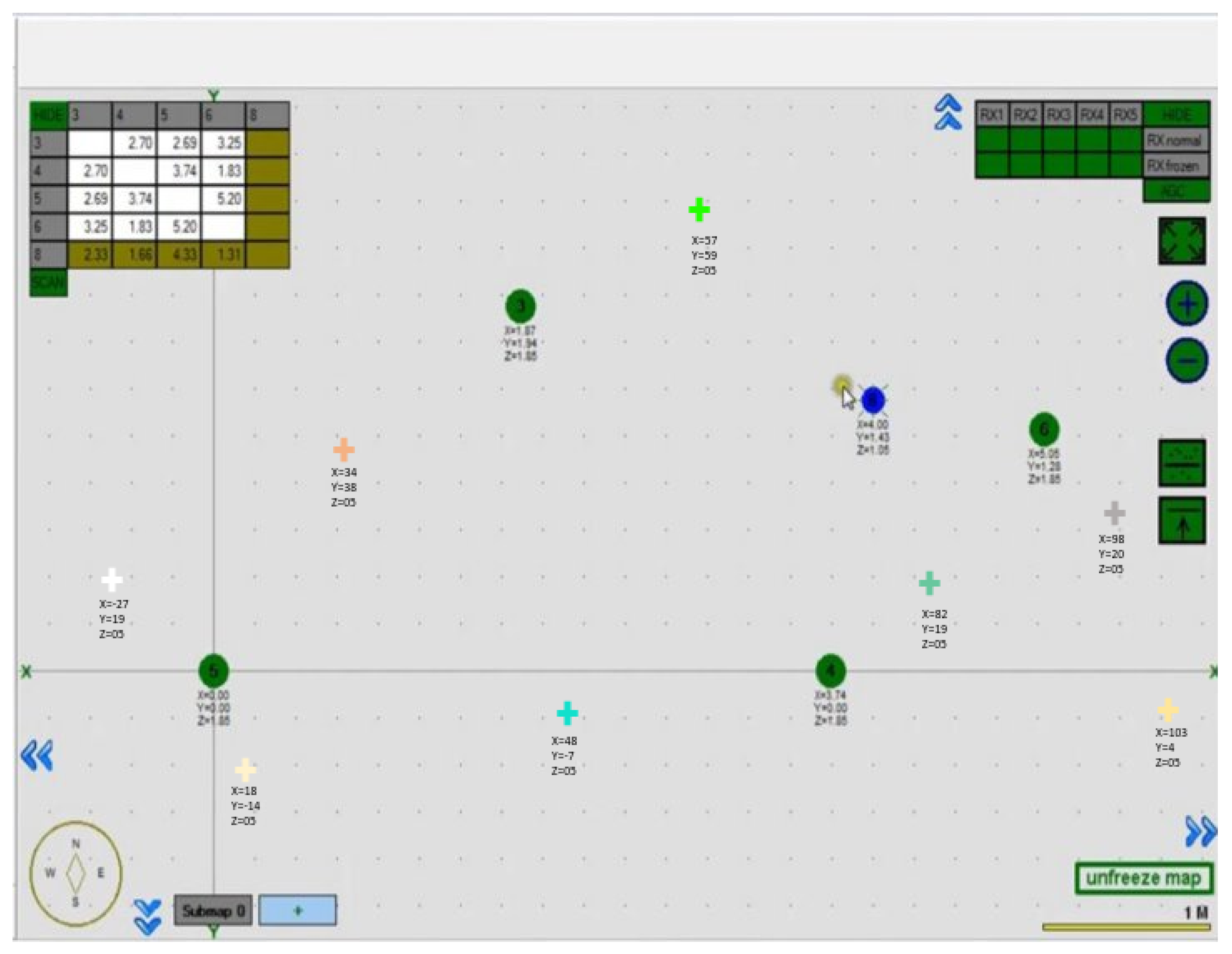
3.3. Deterioration Mapping
3.4. Remote Console
4. Experiments and Results
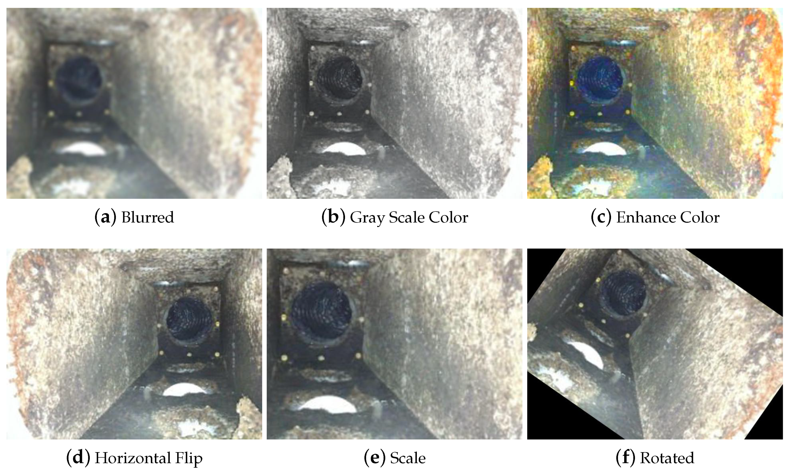
4.1. Data-Set Preparation
4.2. Training and Validation
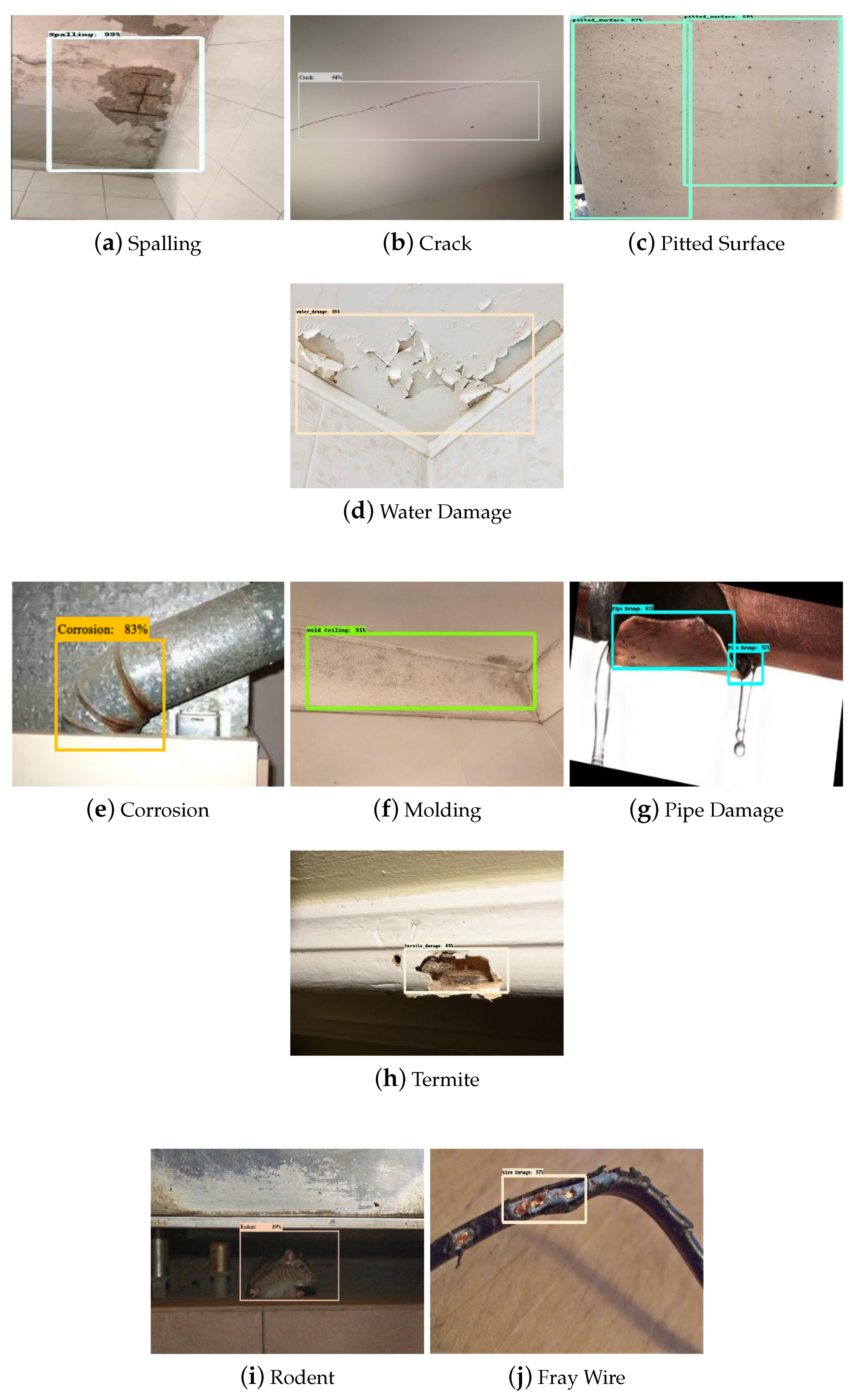
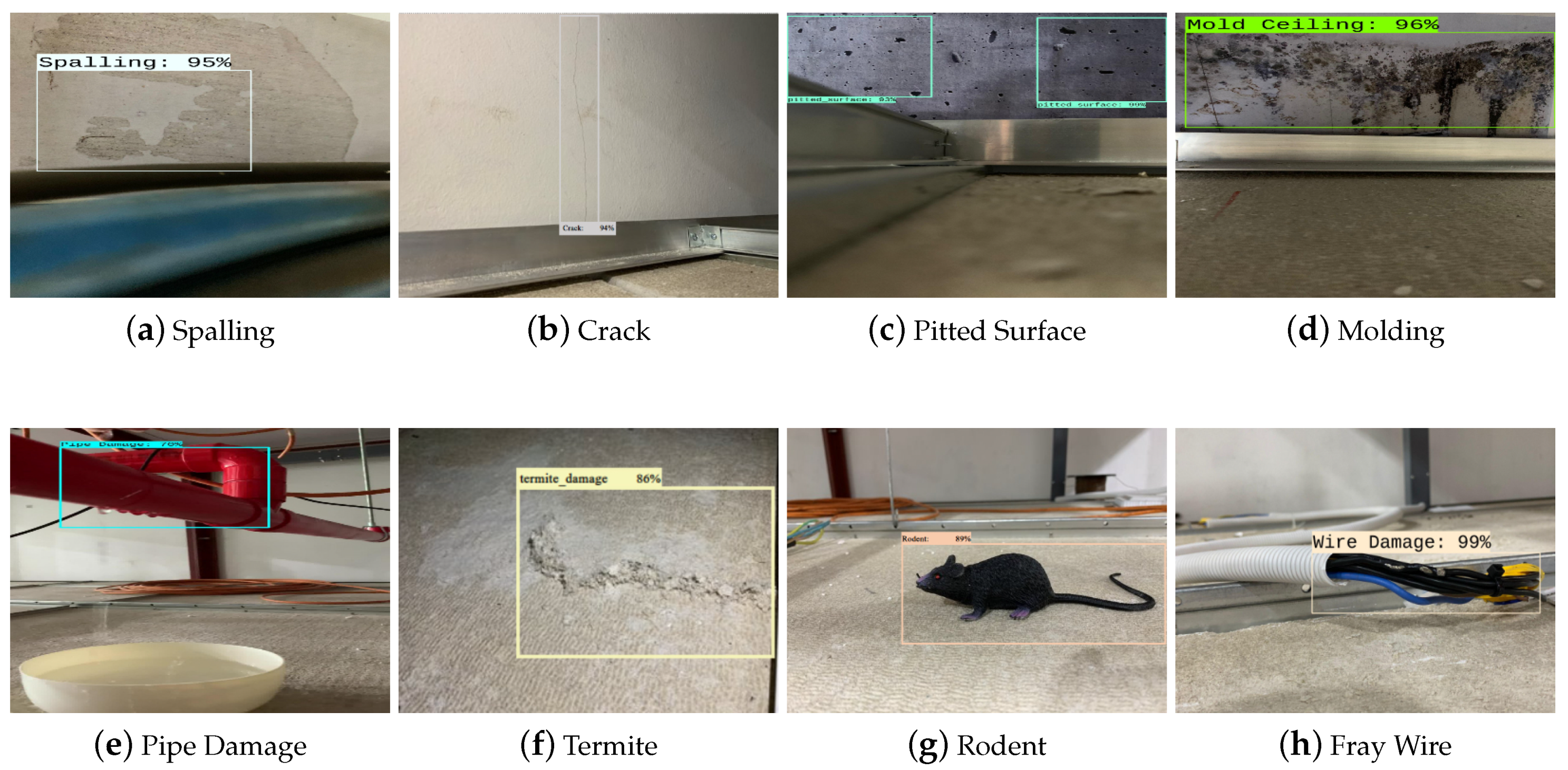
4.3. Prediction with the Test Dataset
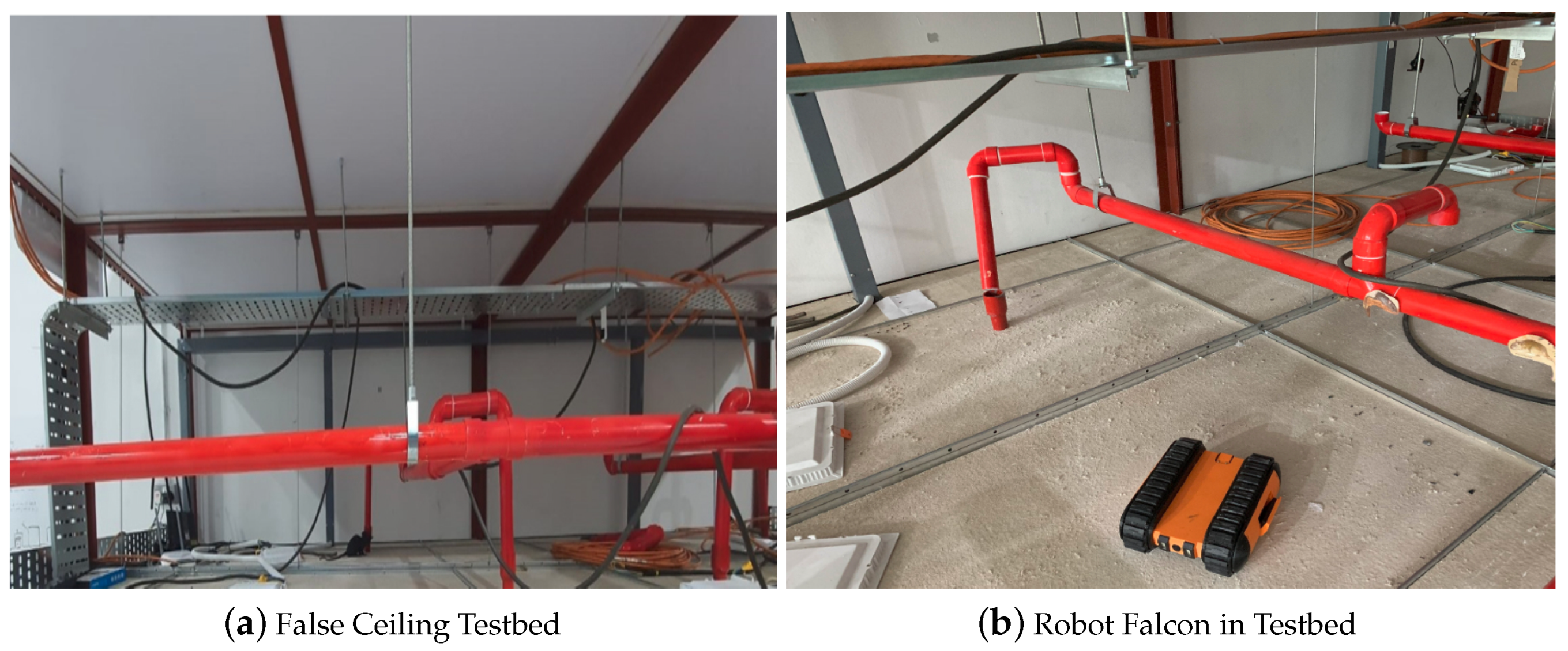
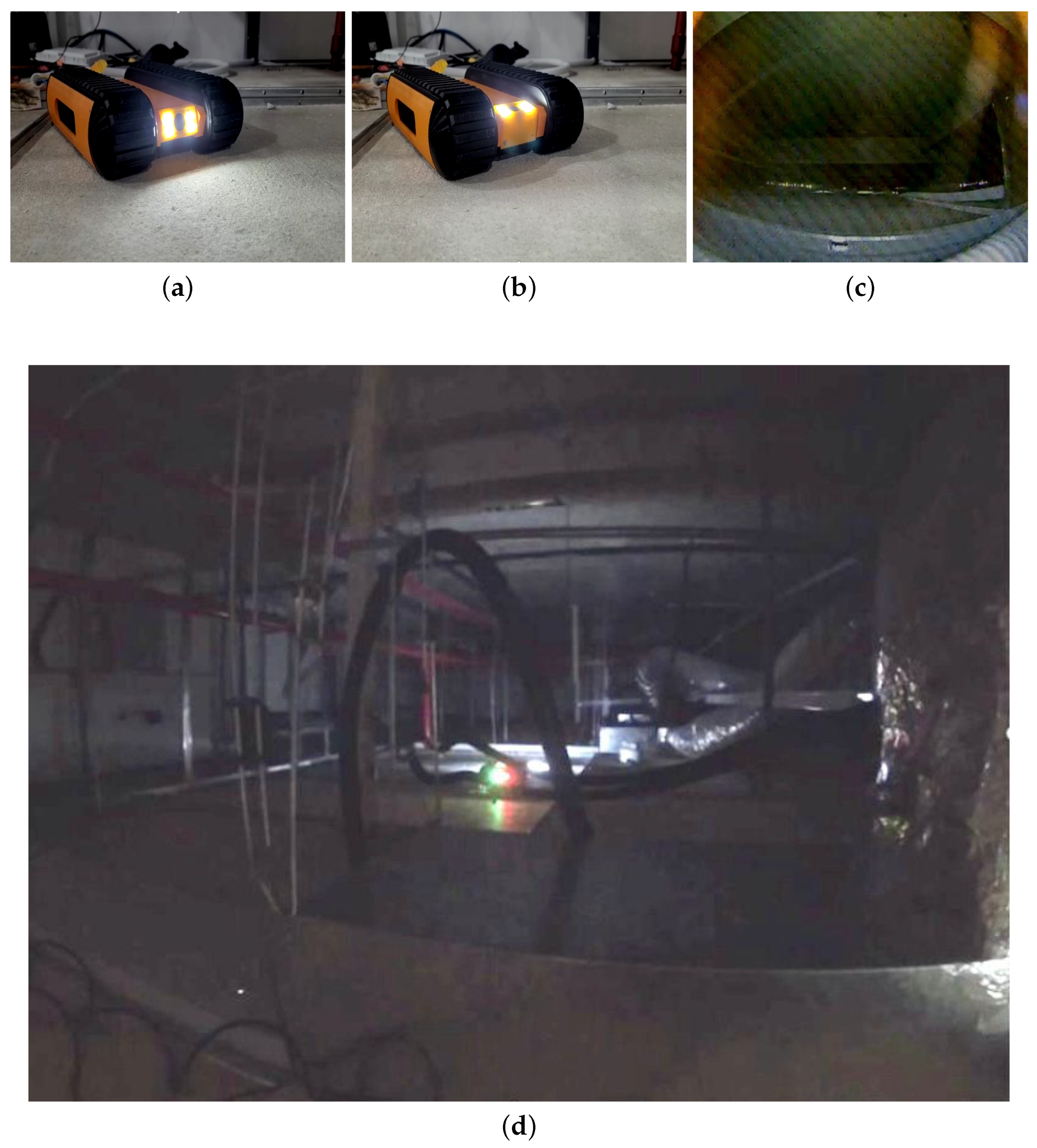
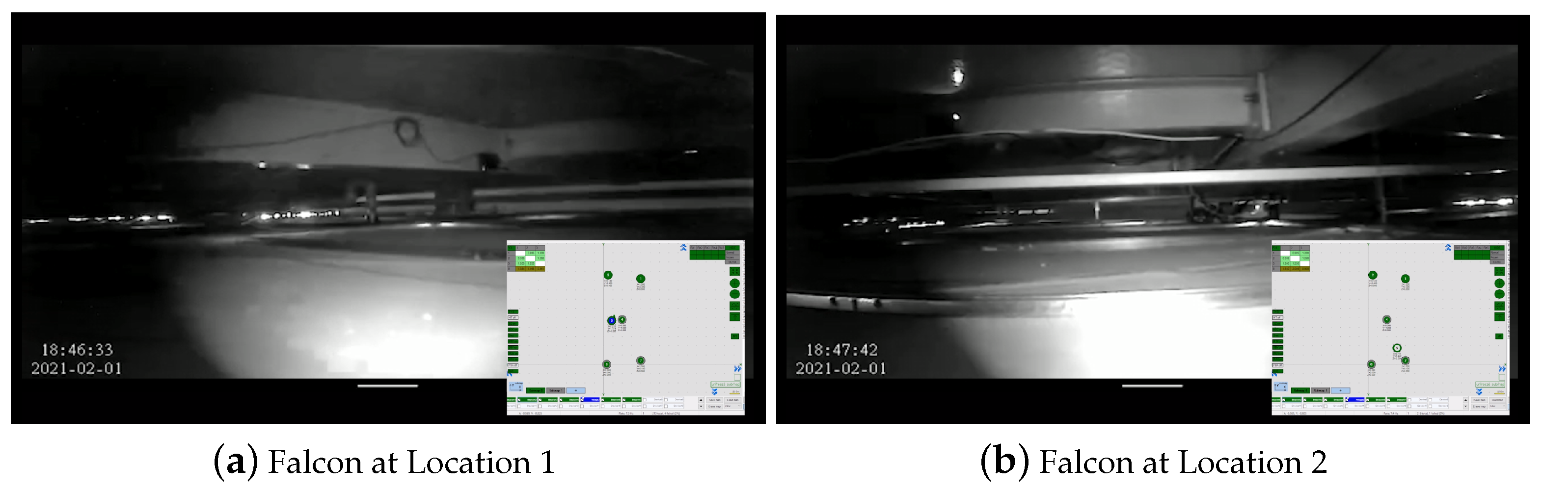
4.4. Real-Time Field Trial
5. Discussion
6. Conclusions
Author Contributions
Funding
Institutional Review Board Statement
Informed Consent Statement
Data Availability Statement
Acknowledgments
Conflicts of Interest
References
- Edgemon, G.L.; Moss, D.; Worland, W. Condition Assessment of the Los Alamos National Laboratory Radioactive Liquid Waste Collection System. In CORROSION 2005; OnePetro: Los Alamos, NM, USA, 2005. [Google Scholar]
- Henry, R.S.; Dizhur, D.; Elwood, K.J.; Hare, J.; Brunsdon, D. Damage to concrete buildings with precast floors during the 2016 Kaikoura earthquake. Bull. N. Z. Soc. Earthq. Eng. 2017, 50, 174–186. [Google Scholar] [CrossRef] [Green Version]
- Jiang, Y.; Han, S.; Bai, Y. Building and Infrastructure Defect Detection and Visualization Using Drone and Deep Learning Technologies. J. Perform. Constr. Facil. 2021, 35, 04021092. [Google Scholar] [CrossRef]
- Aliyari, M.; Droguett, E.L.; Ayele, Y.Z. UAV-Based Bridge Inspection via Transfer Learning. Sustainability 2021, 13, 11359. [Google Scholar] [CrossRef]
- Atkinson, G.A.; Zhang, W.; Hansen, M.F.; Holloway, M.L.; Napier, A.A. Image segmentation of underfloor scenes using a mask regions convolutional neural network with two-stage transfer learning. Autom. Constr. 2020, 113, 103118. [Google Scholar] [CrossRef]
- Ramalingam, B.; Tun, T.; Mohan, R.E.; Gómez, B.F.; Cheng, R.; Balakrishnan, S.; Mohan Rayaguru, M.; Hayat, A.A. AI Enabled IoRT Framework for Rodent Activity Monitoring in a False Ceiling Environment. Sensors 2021, 21, 5326. [Google Scholar] [CrossRef] [PubMed]
- Protopapadakis, E.; Voulodimos, A.; Doulamis, A.; Doulamis, N.; Stathaki, T. Automatic crack detection for tunnel inspection using deep learning and heuristic image post-processing. Appl. Intell. 2019, 49, 2793–2806. [Google Scholar] [CrossRef]
- Menendez, E.; Victores, J.G.; Montero, R.; Martínez, S.; Balaguer, C. Tunnel structural inspection and assessment using an autonomous robotic system. Autom. Constr. 2018, 87, 117–126. [Google Scholar] [CrossRef]
- Palanisamy, P.; Mohan, R.E.; Semwal, A.; Jun Melivin, L.M.; Félix Gómez, B.; Balakrishnan, S.; Elangovan, K.; Ramalingam, B.; Terntzer, D.N. Drain Structural Defect Detection and Mapping Using AI-Enabled Reconfigurable Robot Raptor and IoRT Framework. Sensors 2021, 21, 7287. [Google Scholar] [CrossRef]
- Melvin, L.M.J.; Mohan, R.E.; Semwal, A.; Palanisamy, P.; Elangovan, K.; Gómez, B.F.; Ramalingam, B.; Terntzer, D.N. Remote drain inspection framework using the convolutional neural network and re-configurable robot Raptor. Sci. Rep. 2021, 11, 22378. [Google Scholar] [CrossRef] [PubMed]
- Kouzehgar, M.; Tamilselvam, Y.K.; Heredia, M.V.; Elara, M.R. Self-reconfigurable façade-cleaning robot equipped with deep-learning-based crack detection based on convolutional neural networks. Autom. Constr. 2019, 108, 102959. [Google Scholar] [CrossRef]
- Pan, Z.; Yang, J.; Wang, X.; Wang, F.; Azim, I.; Wang, C. Image-based surface scratch detection on architectural glass panels using deep learning approach. Constr. Build. Mater. 2021, 282, 122717. [Google Scholar] [CrossRef]
- Jamil, M.; Sharma, S.K.; Singh, R. Fault detection and classification in electrical power transmission system using artificial neural network. SpringerPlus 2015, 4, 334. [Google Scholar] [CrossRef] [PubMed] [Green Version]
- Tun, T.T.; Elara, M.R.; Kalimuthu, M.; Vengadesh, A. Glass facade cleaning robot with passive suction cups and self-locking trapezoidal lead screw drive. Autom. Constr. 2018, 96, 180–188. [Google Scholar] [CrossRef]
- La, H.M.; Dinh, T.H.; Pham, N.H.; Ha, Q.P.; Pham, A.Q. Automated robotic monitoring and inspection of steel structures and bridges. Robotica 2019, 37, 947–967. [Google Scholar] [CrossRef] [Green Version]
- Gui, Z.; Li, H. Automated defect detection and visualization for the robotic airport runway inspection. IEEE Access 2020, 8, 76100–76107. [Google Scholar] [CrossRef]
- Perez, H.; Tah, J.H.; Mosavi, A. Deep learning for detecting building defects using convolutional neural networks. Sensors 2019, 19, 3556. [Google Scholar] [CrossRef] [Green Version]
- Xing, J.; Jia, M. A convolutional neural network-based method for workpiece surface defect detection. Measurement 2021, 176, 109185. [Google Scholar] [CrossRef]
- Tao, X.; Zhang, D.; Ma, W.; Liu, X.; Xu, D. Automatic metallic surface defect detection and recognition with convolutional neural networks. Appl. Sci. 2018, 8, 1575. [Google Scholar] [CrossRef] [Green Version]
- Cheon, S.; Lee, H.; Kim, C.O.; Lee, S.H. Convolutional neural network for wafer surface defect classification and the detection of unknown defect class. IEEE Trans. Semicond. Manuf. 2019, 32, 163–170. [Google Scholar] [CrossRef]
- Ladig, R.; Shimonomura, K. High precision marker based localization and movement on the ceiling employing an aerial robot with top mounted omni wheel drive system. In Proceedings of the 2016 IEEE/RSJ International Conference on Intelligent Robots and Systems (IROS), Daejeon, Korea, 9–14 October 2016; pp. 3081–3086. [Google Scholar]
- Zhang, Y.; Dodd, T.; Atallah, K.; Lyne, I. Design and optimization of magnetic wheel for wall and ceiling climbing robot. In Proceedings of the 2010 IEEE International Conference on Mechatronics and Automation, Xi’an, China, 4–7 August 2010; pp. 1393–1398. [Google Scholar]
- Unver, O.; Sitti, M. A miniature ceiling walking robot with flat tacky elastomeric footpads. In Proceedings of the 2009 IEEE International Conference on Robotics and Automation, Kobe, Japan, 12–17 May 2009; pp. 2276–2281. [Google Scholar]
- Hayat, A.A.; Ramanan, R.K.; Abdulkader, R.E.; Tun, T.T.; Ramalingam, B.; Elara, M.R. Robot with Reconfigurable Wheels for False-ceiling Inspection: Falcon. In Proceedings of the 5th IEEE/IFToMM International Conference on Reconfigurable Mechanisms and Robots (ReMAR), Toronto, ON, Canada, 12–14 August 2021; pp. 1–10. [Google Scholar]
- Tan, N.; Hayat, A.A.; Elara, M.R.; Wood, K.L. A framework for taxonomy and evaluation of self-reconfigurable robotic systems. IEEE Access 2020, 8, 13969–13986. [Google Scholar] [CrossRef]
- Manimuthu, M.; Hayat, A.A.; Elara, M.R.; Wood, K. Transformation design Principles as enablers for designing Reconfigurable Robots. In Proceedings of the International Design Engineering Technical Conferences and Computers and Information in Engineering Conference, St. Louis, MO, USA, 17–20 August 2021; pp. 1–12. [Google Scholar]
- Caesar, H.; Uijlings, J.; Ferrari, V. Coco-stuff: Thing and stuff classes in context. In Proceedings of the IEEE Conference on Computer Vision and Pattern Recognition, Salt Lake City, UT, USA, 18–23 June 2018; pp. 1209–1218. [Google Scholar]
- Ren, S.; He, K.; Girshick, R.; Sun, J. Faster r-cnn: Towards real-time object detection with region proposal networks. arXiv 2015, arXiv:1506.01497. [Google Scholar] [CrossRef] [PubMed] [Green Version]
- Guan, S.; Lei, M.; Lu, H. A steel surface defect recognition algorithm based on improved deep learning network model using feature visualization and quality evaluation. IEEE Access 2020, 8, 49885–49895. [Google Scholar] [CrossRef]
- Shi, Y.; Cui, L.; Qi, Z.; Meng, F.; Chen, Z. Automatic road crack detection using random structured forests. IEEE Trans. Intell. Transp. Syst. 2016, 17, 3434–3445. [Google Scholar] [CrossRef]
- Cui, L.; Qi, Z.; Chen, Z.; Meng, F.; Shi, Y. Pavement Distress Detection Using Random Decision Forests. In International Conference on Data Science; Springer: Berlin/Heidelberg, Germany, 2015; pp. 95–102. [Google Scholar]
- Civera, M.; Fragonara, L.Z.; Surace, C. Video processing techniques for the contactless investigation of large oscillations. In Journal of Physics: Conference Series; IOP Publishing: Bristol, UK, 2019; Volume 1249, p. 012004. [Google Scholar]


| Reference | Typology of the Platform | Aim |
|---|---|---|
| Gary et al. [5] | Wheeled Robot | Detect common features of underfloor void |
| Balakrishnan et al. [6] | Tracked Robot | Rodent Activity Monitoring |
| Protopapadakis et al. [7] | Wheeled Robot | Crack detection for tunnel inspection |
| Menendez et al. [8] | Wheeled Robot | Tunnel structural inspection |
| Palanisamy et al. [9] | Wheeled Robot | Drain Structural Defect Detection |
| Melvin et al. [10] | Wheeled Robot | Drain blockage inspection |
| Kouzehgar et al. [11] | Wheeled Robot | Automatic glass crack detection |
| Hung et al. [15] | Wheeled Robot | Inspection of steel structures and bridges |
| Gui et al. [16] | Wheeled Robot | Airport runway inspection |
| Ladig et al. [21] | Aerial Robot | Platform to do high precision localization and positioning |
| Ozgur et al. [23] | Sixteen-legged climbing robot | To climb in any direction in 3D space |
| Hayat et al. [24] | Reconfigurable wheeled robot | False-ceiling inspection |
| Description | Specification |
|---|---|
| Dimension [L × W × H] | 0.236 m × 0.156 m × 0.072 m |
| Weight (including battery) | 1.3 kg |
| Type of Locomotion Drive | Track |
| Top & Bottom Ground Clearance | 0.011 m, 0.011 m |
| Operating Speed | 0.1 m/s |
| Maximum Obstacle Height | 0.055 m |
| Operational Duration | 0.5 h–0.75 h |
| Battery | 3-cell Lithium Ion |
| Operation Mode | Teleoperation (with integrated sensors to detect falls and stops autonomously) |
| Communication Mode | Wi-Fi through a local MQTT server |
| Camera Specifications (onboard light source) | VGA 640 × 480, up to 30 fps, 60 degree view angle, 20 cm-infinity focusing range |
| Layer Details | Input Dimensions |
|---|---|
| Conv | |
| Conv | |
| Conv | |
| Pool | |
| Conv | |
| Conv | |
| Conv | |
| Inception module A | |
| Inception module B | |
| Inception module C | |
| Pool | |
| Linear | |
| Softmax |
| Augmentation Type | Augmentation Setting |
|---|---|
| Blurring | gaussianblur (from sigma 1.0× to 3.0×) |
| Grayscale | individual rgb spectrum (from factor 0 to 1.5×) |
| Color Enhancing | contrast (from 0.5× to 1.5×) |
| Horizontal Flip | flip the image horizontally |
| Scaling | 0.5× to 1.5× |
| Rotation | from −45 degree to +45 degree |
| Translation | X-axis (−0.3× to 0.3×) Y-axis (−0.3× to 0.3×) |
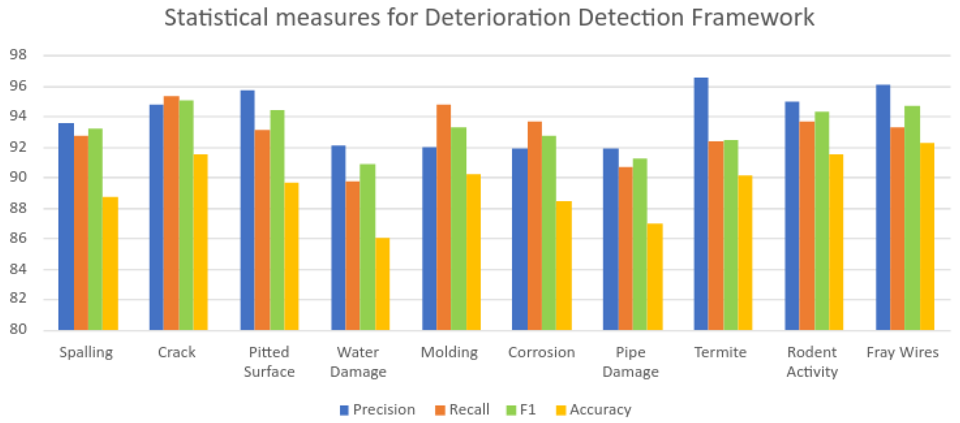
| Category | Class | Precision | Recall | F1 | Accuracy |
|---|---|---|---|---|---|
| Structural Defect | Spalling | 93.60 | 92.77 | 93.16 | 88.70 |
| Crack | 94.77 | 95.32 | 95.04 | 91.50 | |
| Pitted Surface | 95.70 | 93.13 | 94.39 | 89.70 | |
| Water Damage | 92.11 | 89.74 | 90.91 | 86.00 | |
| Degradation in HVAC | Molding | 91.95 | 94.74 | 93.32 | 90.20 |
| Corrosion | 91.88 | 93.63 | 92.74 | 88.50 | |
| Pipe Damage | 91.89 | 90.67 | 91.28 | 87.00 | |
| Infestation | Termite | 96.59 | 92.39 | 94.44 | 90.10 |
| Rodent Activity | 95.01 | 93.63 | 94.31 | 91.52 | |
| Electrical Damage | Fray wires | 96.13 | 93.29 | 94.69 | 92.23 |
| Category | Class | Precision | Recall | F1 | Accuracy |
|---|---|---|---|---|---|
| Structural Defect | Spalling | 87.12 | 86.11 | 86.61 | 86.4 |
| Crack | 90.87 | 90.47 | 90.67 | 90.2 | |
| Pitted Surface | 85.61 | 84.8 | 85.2 | 84.2 | |
| Water Damage | 86.79 | 87 | 86.89 | 84.6 | |
| Degradation in HVAC | Molding | 90.69 | 91.09 | 90.89 | 89.8 |
| Corrosion | 88.86 | 89.27 | 89.07 | 87.6 | |
| Pipe Damage | 85.51 | 84.89 | 85.2 | 83.4 | |
| Infestation | Termite | 85.55 | 86.56 | 86.05 | 84.8 |
| Rodent Activity | 90.38 | 88.99 | 89.68 | 90.8 | |
| Electrical Damage | Fray wires | 90.54 | 88.86 | 89.7 | 86.2 |
| Category | Class | Precision | Recall | F1 | Accuracy |
|---|---|---|---|---|---|
| Structural Defect | Spalling | 88.19 | 88.81 | 88.5 | 85.8 |
| Crack | 92.51 | 92.92 | 92.72 | 90.4 | |
| Pitted Surface | 86.57 | 85.95 | 86.26 | 83.9 | |
| Water Damage | 87.8 | 86.97 | 87.38 | 84.3 | |
| Degradation in HVAC | Molding | 92.05 | 92.46 | 92.27 | 90.2 |
| Corrosion | 88.84 | 87.61 | 88.22 | 87.2 | |
| Pipe Damage | 86.76 | 87.17 | 86.97 | 84.1 | |
| Infestation | Termite | 85.16 | 84.13 | 84.64 | 83.2 |
| Rodent Activity | 93.16 | 92.54 | 92.85 | 91.1 | |
| Electrical Damage | Fray wires | 87.21 | 88.03 | 87.62 | 85.1 |
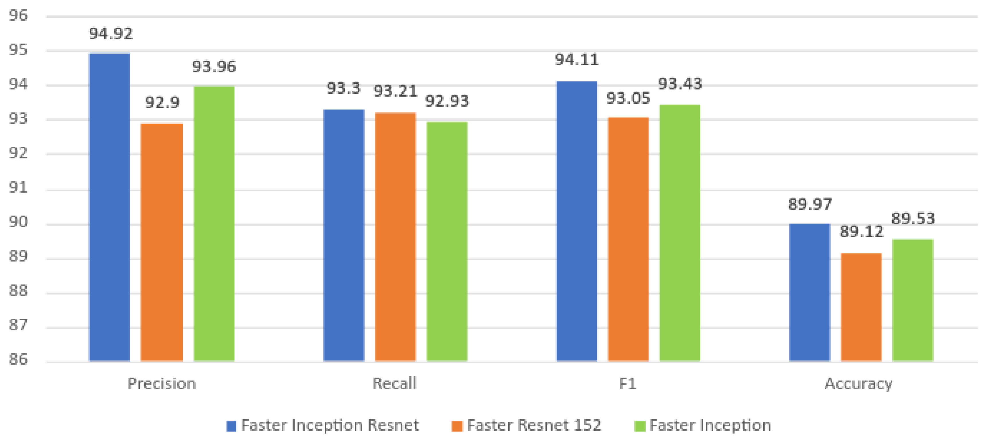
| Class | Precision | Recall | F1 | Overall Accuracy |
|---|---|---|---|---|
| Faster Inception Resnet | 94.92 | 93.3 | 94.11 | 86.5 |
| Faster Resnet 152 | 92.9 | 93.21 | 93.05 | 86.8 |
| Faster Inception (Proposed Model) | 93.96 | 92.93 | 93.43 | 89.53 |
| Algorithm | Training Time (Hours:Minutes) | Speed (Milliseconds) |
|---|---|---|
| Faster Inception Resnet | 23:20 | 647 |
| Faster Resnet 152 | 19:48 | 135 |
| Faster Inception (Proposed Model) | 16:18 | 68 |
| Reference | Algorithm | Accuracy |
|---|---|---|
| Gary et al. [5] | Mask-RCNN | 80.00% |
| Hung La et al. [15] | CNN-based image stitching and 3D registration | 93.10% |
| Gui et al. [16] | CNN-based | 70.00% |
| Perez et al. [17] | VGG-16 | 87.50% |
| Xing et al. [18] | CNN model (SCN) and optimised IoU | 85.84% |
| Xian et al. [19] | Cascaded encoder (CASAE) | 89.60% |
| Cheon et al. [20] | Single CNN | 96.20% |
| Proposed Method | Faster R-CNN Inception | 89.53% |
Publisher’s Note: MDPI stays neutral with regard to jurisdictional claims in published maps and institutional affiliations. |
© 2021 by the authors. Licensee MDPI, Basel, Switzerland. This article is an open access article distributed under the terms and conditions of the Creative Commons Attribution (CC BY) license (https://creativecommons.org/licenses/by/4.0/).
Share and Cite
Semwal, A.; Mohan, R.E.; Melvin, L.M.J.; Palanisamy, P.; Baskar, C.; Yi, L.; Pookkuttath, S.; Ramalingam, B. False Ceiling Deterioration Detection and Mapping Using a Deep Learning Framework and the Teleoperated Reconfigurable ‘Falcon’ Robot. Sensors 2022, 22, 262. https://0-doi-org.brum.beds.ac.uk/10.3390/s22010262
Semwal A, Mohan RE, Melvin LMJ, Palanisamy P, Baskar C, Yi L, Pookkuttath S, Ramalingam B. False Ceiling Deterioration Detection and Mapping Using a Deep Learning Framework and the Teleoperated Reconfigurable ‘Falcon’ Robot. Sensors. 2022; 22(1):262. https://0-doi-org.brum.beds.ac.uk/10.3390/s22010262
Chicago/Turabian StyleSemwal, Archana, Rajesh Elara Mohan, Lee Ming Jun Melvin, Povendhan Palanisamy, Chanthini Baskar, Lim Yi, Sathian Pookkuttath, and Balakrishnan Ramalingam. 2022. "False Ceiling Deterioration Detection and Mapping Using a Deep Learning Framework and the Teleoperated Reconfigurable ‘Falcon’ Robot" Sensors 22, no. 1: 262. https://0-doi-org.brum.beds.ac.uk/10.3390/s22010262