Article

Preparation of Supported Perovskite Catalyst to Purify Membrane Concentrate of Coal Chemical Wastewater in UV-Catalytic Wet Hydrogen Peroxide Oxidation System

College of Environmental Science and Engineering, Nanjing Tech University, Nanjing 211800, China
*
Authors to whom correspondence should be addressed.
Int. J. Environ. Res. Public Health 2021, 18(9), 4906; https://0-doi-org.brum.beds.ac.uk/10.3390/ijerph18094906
Submission received: 16 March 2021 / Revised: 20 April 2021 / Accepted: 21 April 2021 / Published: 4 May 2021

Abstract

:
The effective treatment of membrane concentrate is a major technical challenge faced by the new coal chemical industry. In this study, a supported perovskite catalyst LaCoO3/X was prepared by a sol–impregnation two-step method. The feasibility of the supported perovskite catalyst LaCoO3/X in the UV-catalytic wet hydrogen peroxide oxidation (UV-CWPO) system for the purification of concentrated liquid of coal chemical wastewater was investigated. The effects of catalyst support, calcination temperature, calcination time, and re-use time on catalytic performance were investigated by batch experiments. The catalysts were characterized by X-ray diffraction (XRD), Scanning electron microscopy (SEM), Brunauer–Emmett–Teller (BET), and X-ray photoelectron spectroscopy (XPS). Experimental results showed that the supported perovskite catalyst LaCoO3/CeO2 prepared using CeO2 as support, calcination temperature of 800 °C, and calcination time of 8 h had the best catalytic effect. The catalytic performance of the catalyst remained excellent after seven cycles. The best prepared catalyst was used in UV-CWPO of coal chemical wastewater membrane concentrate. The effects of H2O2 dosage, reaction temperature, reaction pressure, and catalyst dosage on UV-CWPO were determined. Under the conditions of H2O2 dosage of 40 mM, reaction temperature of 120 °C, reaction pressure of 0.5 MPa, catalyst dosage of 1 g/L, pH of 3, and reaction time of 60 min, the removal efficiencies of COD, TOC, and UV254 were 89.7%, 84.6%, and 98.1%, respectively. Under the optimal operating conditions, the oxidized effluent changed from high toxicity to non-toxicity, the BOD5/COD increased from 0.02 to 0.412, and the biodegradability of the oxidized effluent was greatly improved. The catalyst has a simple synthesis procedure, excellent catalytic performance, and great potential in the practical application of coal chemical wastewater treatment.

1. Introduction

Membrane separation technology is often used in the advanced treatment unit of coal chemical wastewater to meet the requirement of “zero discharge” in the coal chemical industry [1]. Membrane separation technology can selectively separate impurities in coal gasification wastewater at the molecular or ion level, but cannot degrade pollutants [2], so a certain amount of membrane concentrate will be produced during treatment. Membrane concentrate has the characteristics of high organic concentration, large chroma, and poor biodegradability [3]. The effective treatment of concentrated membrane solution is a major challenge in the advanced treatment of coal chemical wastewater. Ultraviolet-catalytic wet hydrogen peroxide oxidation (UV-CWPO) technology introduces ultraviolet light into catalytic wet hydrogen peroxide oxidation (CWPO) system to combine photocatalysis and CWPO systems [4,5]. UV-CWPO can completely oxidize refractory organic matter in wastewater and intermediate products produced in wet oxidation into carbon dioxide, H2O, and biodegradable small molecules; this method can deodorize, decolorize, and disinfect at the same time for harmless treatment of toxic wastewater. In addition, UV light itself can make H2O2 produce ·OH with strong oxidation, and the synergistic effect of UV light and catalyst can produce more ·OH more efficiently. Compared with CWPO systems, conventional CWPO systems operate at lower temperatures and pressure levels due to the introduction of UV [6].Some studies have shown the superiority of photocatalytic system. Zazo et al. [7] found that UV radiation can promote the reduction of Fe3+ to Fe2+ on the surface of the catalyst, so that more H2O2 can be decomposed into hydroxyl radical ·OH. In addition, UV radiation can easily mineralize oxalic acid, which greatly reduces the leaching of active phase and prolongs the service life of the catalyst. The catalyst is the key to UV-CWPO technology. The active components in a catalyst can reduce the reaction conditions and improve the reaction efficiency. Therefore, finding a highly efficient and stable catalyst is an important challenge to popularize this technology [8].
A perovskite-type catalyst is a composite metal oxide with a cubic crystal structure and has the advantages of controllable structure, good thermal stability, high catalytic efficiency, and strong redox ability [9]. This catalyst is widely used in flue gas desulfurization, catalytic combustion, tail gas purification, wastewater treatment, and other fields [10,11,12]. Hsu et al. [13] successfully synthesized LaFeO3 by sol–gel method. The removal efficiency of tricholorethylene (TCE) in aqueous solution using LaFeO3 (2 g/L) as photocatalyst can reach 95% within 1 h after xenon lamp irradiation. Burcu Palas et al. [14] used LaNiO3 perovskite catalyst in the decolorization study of catalytic wet oxidation of active black 5 azo dye wastewater. Under the conditions of catalyst dosage of 1 g/L, reaction temperature of 50 °C, reaction pressure of 1 MPa, pH of 3, and initial solution concentration of 100 mg/L, the degradation and decolorization rates of reactive black 5 solution were 65.4% and 89.6%, respectively. The perovskite-type catalyst has great application prospect in the field of UV-CWPO. It cannot only meet the performance requirements of CWPO system, but also fully cooperate with ultraviolet light in the system. However, perovskite-type catalysts generally have the disadvantage of small specific surface area. Supporting these catalysts with large specific surface area to obtain more dispersed active components is a research hotspot [15].
This study used sol impregnation method and selected a variety of supports to synthesize supported perovskite catalyst. The catalytic activity of several benchmark catalysts was tested to screen a desirable carrier and obtain high-quality supported perovskite catalyst LaCoO3/X. The effects of calcination temperature and duration on the wastewater purification efficiency of the catalyst were investigated by batch experiments. The physical and chemical properties of the catalyst were characterized by XRD, SEM, BET, and XPS. Finally, the catalysts obtained under the optimal preparation conditions were used in the UV-CWPO system to purify coal chemical wastewater membrane concentrate. The optimal process conditions including H2O2 dosage, catalyst dosage, reaction temperature, and reaction pressure were explored. Toxicity test and biodegradability analysis of the oxidized effluent were also carried out.

2. Materials and Methods

2.1. Chemicals and Materials

All chemicals used in this study were analytical reagents without further purification. Lanthanum nitrate (La(NO3)3·6H2O) was purchased from Shanghai Lingfeng Chemical Reagent Co., Ltd. (Shanghai, China). Cobalt nitrate (Co(NO3)2·6H2O), citric acid (C6H8O7·H2O), cerium oxide (CeO2), potassium dichromate (K2Cr2O7), and silver sulfate (Ag2SO4) were acquired from Sinopharm Reagent Co., Ltd. (Shanghai, China). Activated alumina, nano titanium oxide (TiO2), concentrated sulfuric acid (H2SO4), sodium hydroxide (NaOH), hydrogen peroxide (H2O2, 30%), and phenanthroline were obtained from Nanjing Chemical Reagent Co., Ltd. (Nanjing, China). Mercury sulfate (HgSO4) and ammonium ferrous sulfate (H8FeN2O8S2·6H2O) were provided by Shanghai Triangsihewei Chemical Co., Ltd. (Shanghai, China). Deionized water was produced by a pure water treatment system (EPED-Z1-30T, Eped Technology, Beijing, China) and used to prepare all solutions (resistivity ≥ 1 MΩ·cm).
Wastewater was obtained from a coal-to-natural gas wastewater advanced treatment unit in Inner Mongolia. Membrane concentrate characteristics were COD 1510 mg/L, pH 7.86, TOC 658 mg/L, UV254 1.562, NH4‒N 3170 mg/L, and total dissolved solid content 6200 mg/L.

2.2. Preparation of Materials

Supported perovskite catalyst LaCoO3/X (X = CeO2, TiO2, Al2O3) was prepared by sol impregnation method. According to the stoichiometric ratio (La(NO3)3·6H2O): (Co(NO3)2·6H2O) = 1:1, (metal ion):(C6H8O7·H2O) = 1:1.5, certain amounts of La(NO3)3·6H2O, Co(NO3)2·6H2O, and C6H8O7·H2O were weighed and dissolved in deionized water to form a mixed solution. Several carriers were impregnated in the solution by constant-volume impregnation method. The mixed solution was oscillated in an ultrasonic oscillator for 30 min, filtered, and placed in an oven. The samples were dried at 105 °C until they were completely dried. The samples were finely ground and placed in a muffle furnace. Perovskite catalyst LaCoO3/X was obtained by roasting at the corresponding temperature(500–1000 °C) for the corresponding time (5–10 h).
The crystal phase structure of the catalyst was characterized by X-ray diffraction analyzer (XRD, XD-6 type, Beijing Purkay General Instrument Co. Ltd., Beijing, China). At 36 kV and 20 mA, XRD analysis was carried out under monochromatic Cu Kα radiation (λ = 1.54056 Å) within the 2θ scan range of 10°–80°.The specific surface area, pore volume, and pore size distribution of the catalysts were measured using an N2 adsorption and desorption analyzer [BET, Micromeritics TriStar Ⅱ type 3020, McMurdo red 2 g (Shanghai, China) Instrument Co., Ltd.]. Scanning electron microscope (SEM, S3400N Ⅱ type, Japan Hitachi) was used to observe the surface morphology and analyze the load cases of the catalysts. Before the test, a thin layer of gold was plated on the sample surface to improve the electrical conductivity under the test voltage of 10.00 kV. The valence states of elements on the catalyst surface were analyzed by X-ray photoelectron spectroscopy (XPS, AXIS-ULTRA DLD-600 W, Shimadzu, Japan). Al Kα was used as excitation source, and the experimental resolution was higher than 0.1 eV. All recorded lines were calibrated to C1s at 284.8 eV line.

2.3. Degradation Experiments and Analytical Method

A UV-CWPO system was used to treat coal chemical wastewater membrane concentrate.The UV-CWPO system consists of a 500 mL photochemical high-pressure reactor (TFM-500, (Beijing Zhongjiao Jinyuan Technology Co., Ltd., Beijing, China) and a 30W UV deuterium light source (CE-DD30T, Beijing Zhongjiao Jinyuan Technology Co., Ltd., Beijing, China), as shown in Figure 1.
Three catalytic oxidation experiments were conducted in parallel at the same time, and the average value was obtained for subsequent data analysis and discussion. In an independent catalytic oxidation experiment, 250 mL of water sample was mixed with dilute sulfuric acid to adjust the pH to 3 and placed in a 500 mL photochemical high-pressure reactor. Certain amounts of H2O2 (10–60 mM) and catalyst (0.4–1.4 g/L) were added, and air at certain pressure (0.5–1.7 MPa) was added. The reaction temperature was set at 60 °C–160 °C, and the 30 W UV-deuterium lamp source was turned on when the set temperature was reached. Samples were obtained at different reaction intervals for analysis. The recycling performance of the catalyst was investigated under the optimal process conditions. The COD of the water samples was determined by the potassium dichromate method. Total organic carbon analyzer (TOC, TOC-L, Shimadzu Company, Osaka, Japan) was used to measure the TOC of water samples. Generally speaking, the UV254 value is the absorbance of some organic matter in water under the ultraviolet light at 254 nm. UV254 reflects the quantity of humic macromolecular organic compounds and aromatic compounds containing C=C double bond and C=O double bond naturally occurring in water. Phenolic compounds were the main representative compounds in the membrane concentrate, thereby it was necessary to choose UV254 as the water quality index. A UV-Vis spectrophotometer (UV-2600, Shimadzu Company, Osaka, Japan) was used to measure water UV254 at 254 nm wavelength.
The BOD5 of the water samples was determined using hash BOD tester (BODTrak II type, Loveland, CO, USA) to investigate biochemical changes during liquid waste processing. The method for determination of the influence of chemical substances on the microbial metabolism of the Organization for Economic Cooperation and Development (OCED) was used as reference. The influence of the wastewater sample on the respiration rate of activated sludge was measured by a biological respiration meter (PF-8100, RSA Corporation, Danbury, CT, USA) to assess the biological toxicity of wastewater. The pH of wastewater to be tested was adjusted to 7.5 ± 0.5 by adding sodium hydroxide or hydrochloric acid to ensure the acid–base environment required for normal growth of activated sludge. About 250 mL of the activated sludge was placed in a 500 mL reaction flask. OCED medium and water samples were added. After the test was started, the biological respirator automatically recorded oxygen consumed in the reactor. According to the oxygen consumption rate in a certain period of time, respiratory inhibition rate was calculated by Formula (1) [16].
Respiratory depression rate = (OURblank − OURsample)/OURblank

3. Results and Discussion

3.1. Optimization of Catalyst Preparation Conditions

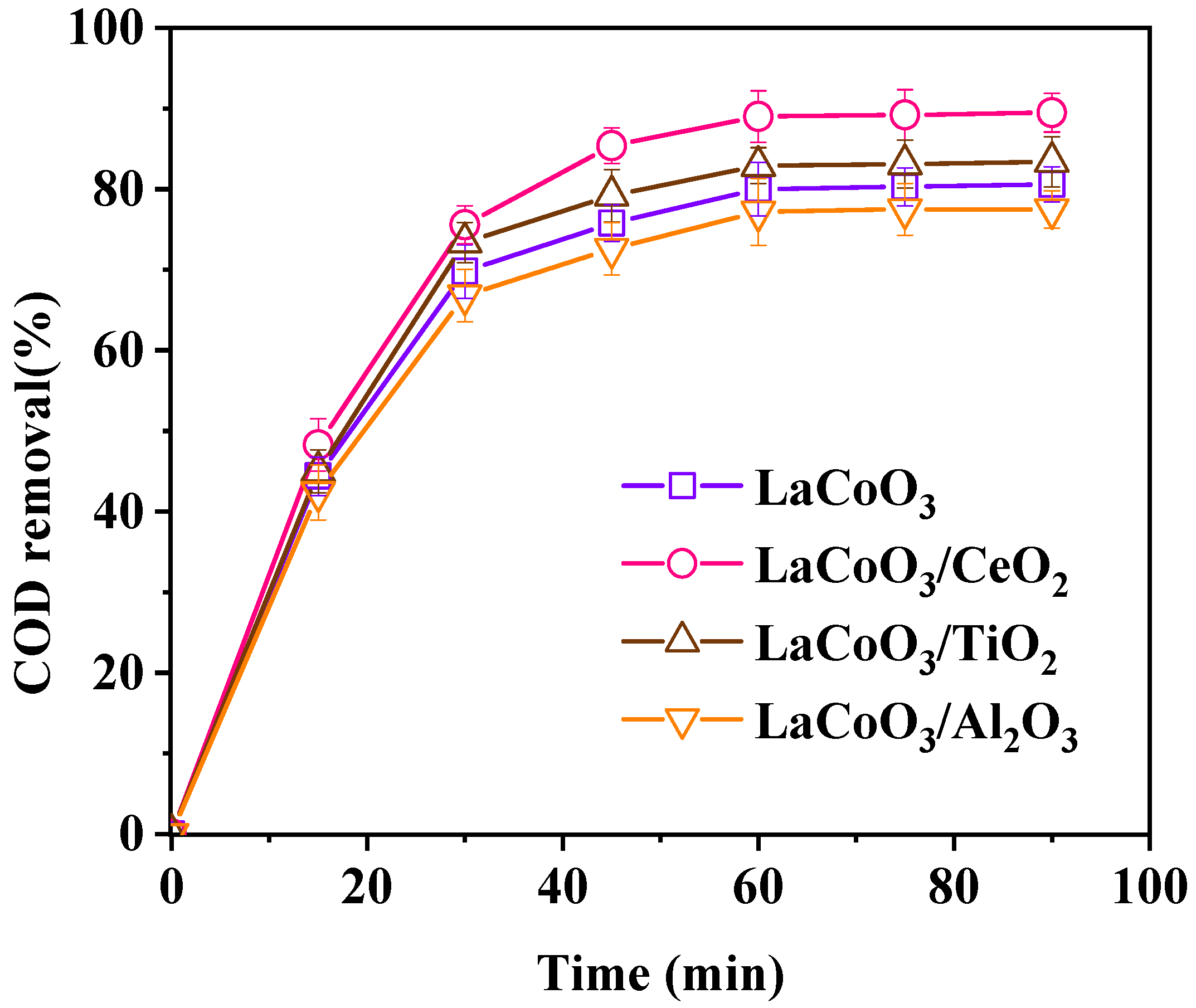
3.1.1. Effect of Catalyst Support

Figure 2 shows the influence of different supports on the catalytic effect of the catalyst. The order of catalytic performance is: LaCoO3/CeO2 > LaCoO3/TiO2 > LaCoO3 > LaCoO3/Al2O3. The supported perovskite catalyst LaCoO3/Al2O3 had the worst catalytic effect. The COD removal efficiency was only 77.5% when the reaction time reached 90 min, which was lower than the COD removal efficiency (80.6%) of LaCoO3 in the same reaction time. When Al2O3 was used as the carrier, Al2O3 invaded the lattice of LaCoO3 and changed the inherent structure of LaCoO3, thereby affecting the catalytic activity of the LaCoO3/Al2O3 composite material [17]. The supported perovskite catalysts LaCoO3/CeO2 and LaCoO3/TiO2 had better catalytic effects than the original LaCoO3, and the former had the best catalytic performance. The COD removal efficiency reached 89.5% when the reaction reached 90 min. The catalytic activity of the supported TiO2 catalyst was improved because the support (TiO2) produced photocatalytic effect with ultraviolet light in the system [18]. When CeO2 was used as the support, CeO2 improved the thermal stability and oxygen storage capacity of the catalyst. Cerium-based catalysts would not enter the crystal lattice of perovskite, similar to commonly used transition metal cations (e.g., La, Co, Fe, Mn). Thus, LaCoO3/CeO2 exhibited better catalytic activity [19]. Therefore, CeO2 was selected as catalyst support to prepare supported perovskite catalyst LaCoO3/CeO2 for subsequent experiments.

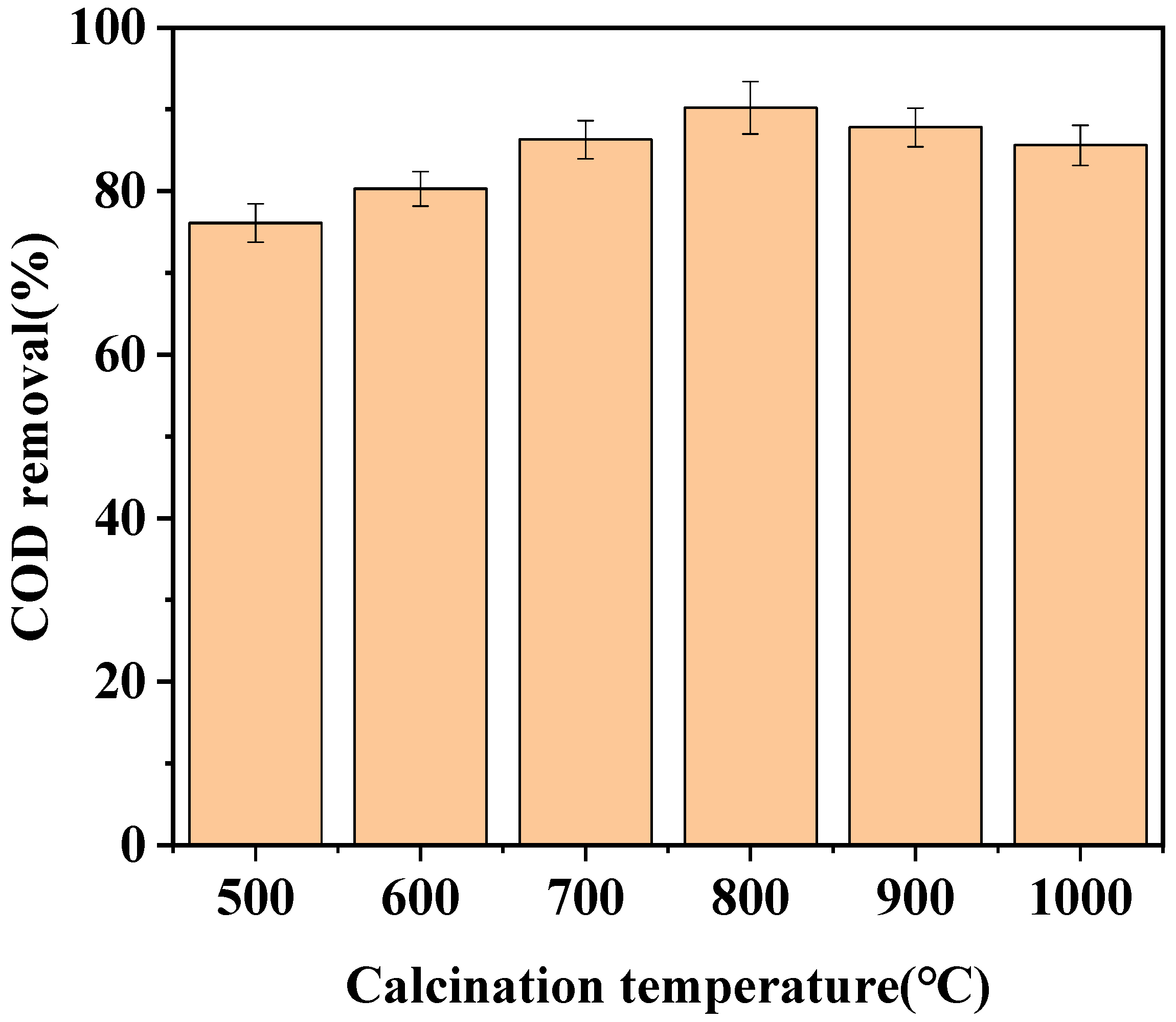
3.1.2. Effect of Calcination Temperature

The effects of different calcination temperatures (500 °C, 600 °C, 700 °C, 800 °C, 900 °C, and 1000 °C) on the catalytic activity of LaCoO3/CeO2 were investigated (Figure 3). With increasing roasting temperature, the catalytic effect of the catalyst was gradually improved.The catalyst with calcination temperature of 800 °C performed the best catalytic effect, and the COD removal efficiency reached 90.2%. The catalytic activity of the catalyst did not continue to increase and even began to decrease when the calcination temperature exceeded 800 °C. The COD removal efficiency only reached 85.6% by the catalyst with the calcination temperature of 1000 °C. The perovskite structure of the catalyst on the CeO2 carrier had not been formed when the calcination temperature was in a lower range, and the purity of the effective perovskite structure was also relatively low, resulting in lower catalyst activity [20]. Meanwhile, if the calcination temperature was too high, the catalyst was prone to sintering, resulting in the collapse of the internal structure of the catalyst, blockage of the pores, and reduction of active sites, which in turn led to the degradation of the catalytic activity [21]. In summary, 800 °C was selected as the best calcination temperature of LaCoO3/CeO2.

3.1.3. Effect of Calcination Time

The effects of different calcination times (5, 6, 7, 8, 9, and 10 h) on the catalytic activity of LaCoO3/CeO2 were investigated (Figure 4). As the calcination time of the catalyst increased, the catalytic effect gradually improved. When the calcination time was 8 h, the catalytic effect reached the highest, and the COD removal efficiency reached 91.1%. As the calcination time continued to increase, the catalytic activity of the catalyst began to decrease gradually. The COD removal efficiency only reached 86.4% by the catalyst after calcination 10 h. Due to the short calcination process, the complexing agent in the catalyst was not completely burned out, so the structure of the catalyst was unstable, the pore was not clear, and the active point formed was less. Thus, the catalyst with a shorter calcination time showed poor catalytic performance [22].
When the calcination time was too long, a perovskite catalyst structure was formed on the CeO2 support and part of the catalyst was sintered and agglomerated, thereby decreasing the specific surface area [23], destroying the active point of the catalyst, and reducing the catalytic effect. Therefore, 8 h was selected as the best roasting time for the catalyst.

3.2. Characterization of Catalysts

3.2.1. X-ray Diffraction (XRD)

The crystal phase structures of LaCoO3 and LaCoO3/CeO2 are shown in Figure 5. Characteristic diffraction peaks of LaCoO3 perovskite structure prepared by the sol–gel method were found at 33.04°, 47.65°, and 59.08°, consistent with the standard card of LaCoO3 (PDF#48-0123). This finding indicated the effectiveness of the preparation method. The prepared catalyst had a pure perovskite structure and orthogonal crystal. The XRD spectra of the supported catalyst LaCoO3/CeO2 prepared by impregnation showed not only obvious characteristic diffraction peaks of LaCoO3 perovskite structure but also characteristic peaks of CeO2 at 29.08°, 33.04°, and 56.51°, corresponding to the standard card of CeO2 (PDF#1-800) [24]. This result confirmed that an LaCoO3 perovskite-type structure was formed on the surface of the CeO2 support, and the crystal forms of the support and active component were not destroyed.

3.2.2. N2 Adsorption/Desorption Analysis

The specific surface area and pore texture information of LaCoO3 and LaCoO3/CeO2 are listed in Table 1. The specific surface area of LaCoO3/CeO2 increased from 2.685 m2/g of pure LaCoO3 to 13.073 m2/g, the pore volume increased from 0.006297 cm3/g to 0.052408 cm3/g, and the pore diameter was 4.0569 nm. With increasing specific surface area and pore volume, the active points on the catalyst surface also increased, and the catalytic activity became stronger [25].

3.2.3. Scanning Electron Microscopy (SEM)

Figure 6 shows the morphology and structure of LaCoO3/CeO2. As shown in Figure 6a, the composite metal oxide LaCoO3 was distributed on the surface of the CeO2 carrier in the form of uniform crystal particles. Although particles were closely connected, the gap between them were clearly seen. In addition, although the LaCoO3 particles on the surface of the support are partially sintered, there are still a large number of pores on the crystal surface and between the crystal structures (Figure 6b,c). Increasing the active point of the catalyst and the contact area between the catalyst and the reactants was conducive to the catalytic reaction [26]. In conclusion, the supported LaCoO3/CeO2 catalyst had a larger specific surface area and higher catalytic activity, consistent with the microscopic characterization and macroscopic experimental results.

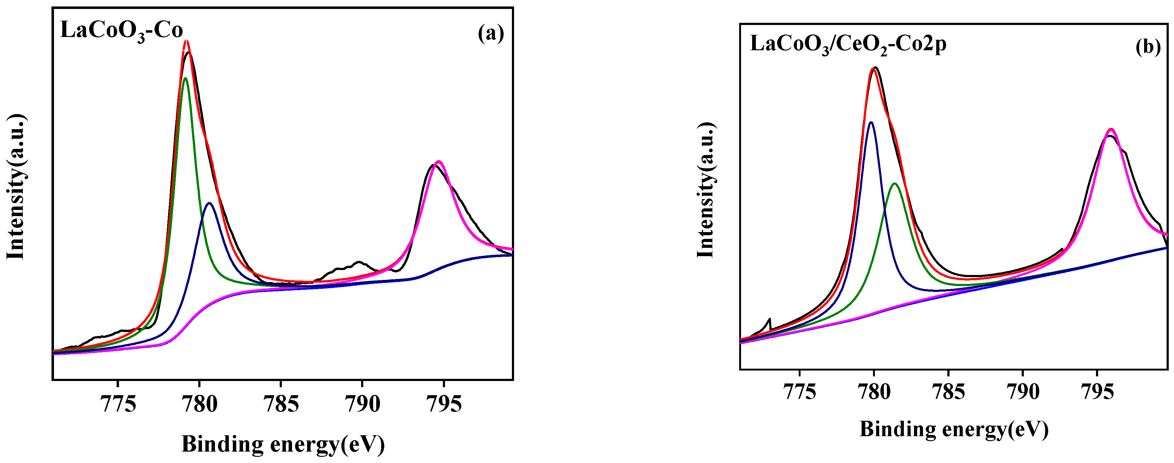
3.2.4. X-ray Photoelectron Spectroscopy (XPS)

The surface element analysis results of the LaCoO3/CeO2 catalysts are shown in Figure 7, Figure 8 and Figure 9. Figure 7a,b shows the La 3D XPS spectra of LaCoO3 and LaCoO3/CeO2 catalysts, respectively. Two pairs of bimodals appeared in both spectra. Two pairs of bimodals located at the lower binding energy (A: 833.8 and 837.7 eV; B: 834.2 and 838.1 eV) were attributed to La 3d3/2 and La 3d5/2. The two pairs of double peaks located at the higher binding energy position were the carrying peak generated by the main peak orbital spin fission, consistent with the characteristic peak of La3+ [27] and confirming the existence of La in LaCoO3 and LaCoO3/CeO2 catalysts. Figure 8a,b shows the XPS spectra of Co2P of LaCoO3 and LaCoO3/CeO2 catalysts, respectively, in the vicinity of 795.5 eV (a: 795.1 eV; B: 795.8 eV) and around 780 eV (A: 779.8 eV; B: 780.1 eV) were attributed to Co 2P1/2 and Co 2P3/2, respectively. Peak-splitting fitting was performed for Co 2P3/2, which was near 779 eV (A: 779.1 eV; B: 779.3 eV) and 781 eV (A: 780.9 eV; B: 781.3 eV) corresponding to Co3+ and Co2+, respectively. This finding suggested that Co in LaCoO3 and LaCoO3/CeO2 catalysts existed in the form of CO3+ and CO2+, respectively [28].
Figure 9a,b show the XPS spectra of O 1s of LaCoO3 and LaCoO3/CeO2 catalysts, respectively. At around 528.5 eV in the two spectra (A: 528.3 eV; B: 528.7 eV) and 531 eV (A: 530.8 eV; B: 531.2 eV), the two main peaks were attributed to lattice oxygen (OL) and surface adsorbed oxygen (OS) [29]. The relative contents of lattice oxygen (OL) and surface adsorbed oxygen (OS) in LaCoO3 and LaCoO3/CeO2 catalysts were calculated according to the ratio of the peak area of Co3+ and Co2+ (Table 2). With the addition of CeO2 support, the ratio of Co3+/Co2+ in the catalyst was close to 1, indicating that the mutual conversion between Co3+ and Co2+ in LaCoO3/CeO2 supported catalyst gradually reached a balance. The oxygen vacancy was formed during charge balance, which was beneficial to the improvement of catalytic activity [30]. The OL/OS ratio increased from 0.80 to 1.48, indicating that the lattice oxygen defects increased in the supported catalysts. The lattice oxygen defect was beneficial to increase the active point of the catalyst, thus improving the catalytic effect of the catalyst [31].

3.3. Degradation Experiments

3.3.1. Comparison to Several Kinds of Reaction Systems

Figure 10 showed that COD removal efficiency of wastewater by UV photocatalysis was quite low, only 16.6%. The reason for this phenomenon was that UV photocatalytic oxidation was limited by reaction conditions and light could not penetrate the turbid solution. The COD removal efficiency in wastewater by CWPO was 75.9%. The removal efficiency of COD in wastewater by UV-CWPO was the best. COD removal efficiency as high as 89.7% when the reaction reached 60 min, and its trend was basically stable after 60 min. Therefore, the UV-CWPO system proves that the combination of UV and CWPO technologies can produce beneficial effects and improve the COD removal efficiency.

3.3.2. Effect of H2O2 Dosage on Wastewater Purification

The influence of different H2O2 dosages on wastewater purification is shown in Figure 11. With increasing H2O2 dosage, the removal efficiencies of COD, TOC, and UV254 in wastewater increased. When the H2O2 dosage reached 40 mM, the removal efficiencies of COD, TOC, and UV254 reached the maximum values of 88.5%, 81.2%, and 97.9%, respectively. When the H2O2 dosage exceeded 40 mM, the removal efficiency of UV254 had no significant increase, while the removal efficiencies of COD and TOC showed a downward trend. With the increase of H2O2 dosage, more ·OH was produced, which enhanced the oxidation capacity of the reaction system [32]. When the concentration of H2O2 was too high, excess H2O2 was decomposed with ·OH in the reaction system, inhibiting the oxidation capacity of the system and causing the waste of oxidants [33]. Overall, the optimal dosage of H2O2 was 40 mM.

3.3.3. Effect of Reaction Temperature on Wastewater Purification

The effect of different reaction temperatures on wastewater purification is shown in Figure 12. As the reaction temperature increased within 60 °C–160 °C, the removal efficiencies of COD, TOC, and UV254 in wastewater increased continuously at first and then tended to be stable. When the reaction temperature was 120 °C, the removal efficiencies of COD, TOC, and UV254 reached the maximum values of 88.5%, 86.7%, and 97.9%, respectively. The gradual increase in the reaction temperature in the initial stage accelerated the reaction process between organic matter in wastewater and ·OH, thereby continuously increasing the rate of the reaction system [34]. When the temperature continued to rise, the removal efficiencies of COD, TOC, and UV254 tended to be stable without significant changes. Therefore, the optimal reaction temperature was 120 °C.

3.3.4. Effect of Reaction Pressure on Effluent Purification

The effect of different reaction pressure levels on wastewater purification is shown in Figure 13. With increasing reaction pressure, the removal efficiencies of COD, TOC, and UV254 remained basically unchanged. When the reaction pressure was 0.5 MPa (the saturated vapor pressure of water at 120 °C is 0.2 MPa), the removal efficiencies of COD, TOC, and UV254 reached 89.2%, 84.5%, and 97.1%, respectively. Increase in the reaction pressure had no significant effect on oxidation. In the UV-CWPO system, the oxidation process between H2O2 and pollutants is the main body, and the mass transfer of oxygen from the gas phase to the liquid phase is less than that in the CWPO system, thereby reducing energy consumption [35,36]. Therefore, the system can oxidize and degrade pollutants under low-pressure conditions. Considering the oxidation effect and safety, the optimal reaction pressure was 0.5 MPa.

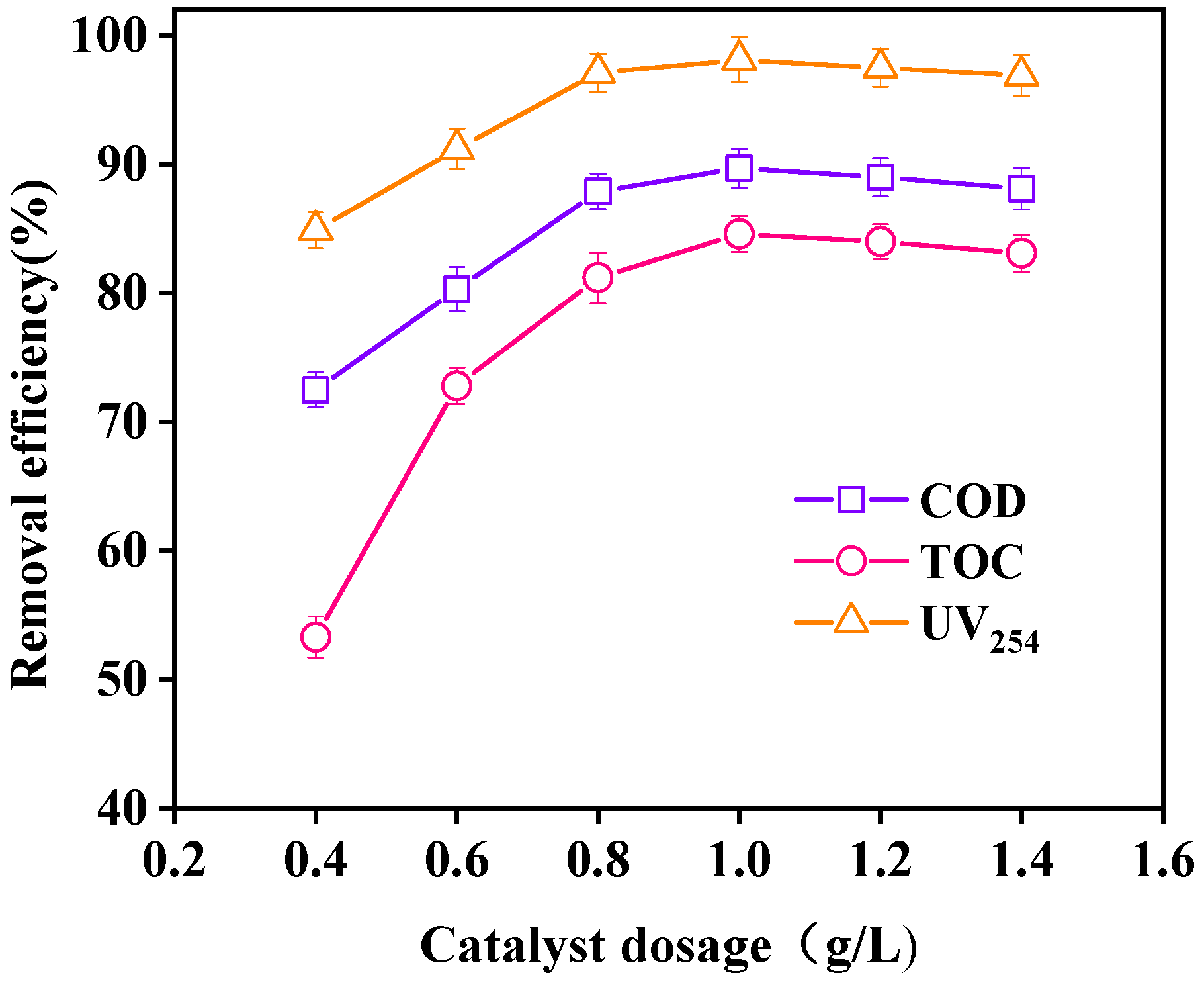
3.3.5. Effect of Catalyst Dosage on Wastewater Purification

The effect of different dosages of catalyst on wastewater purification is shown in Figure 14. With increasing catalyst dosage, the removal efficiencies of COD, TOC, and UV254 in wastewater showed a trend of increasing first and then decreasing. When the dosage of the catalyst was 1 g/L, the removal efficiencies of COD, TOC, and UV254 reached 89.7%, 84.6%, and 98.1%, respectively. With increasing catalyst dosage, the active points on the catalyst surface increased, and the decomposition rate of H2O2 to produce ·OH was accelerated, thereby increasing the oxidation rate. When the dosage of the catalyst was greater than 1 g/L, the light transmittance of wastewater was negatively affected, which was not conducive to the absorption of ultraviolet light. The oxidation effect then decreased slightly [37]. Therefore, the optimal dosage of the catalyst was 1 g/L.

3.4. Reusability and Stability of Catalyst

Seven cyclic degradation experiments were carried out to evaluate the reusability and stability of the LaCoO3/CeO2 catalyst (Figure 15). The removal efficiencies of COD, TOC, and UV254 reached 88.3%, 82.8%, and 96.3% after seven times of repeated use, which were not significantly lower than the removal efficiencies of the first use. Hence, the LaCoO3/CeO2 catalyst had good reusability and stability.

4. Biodegradability Analysis

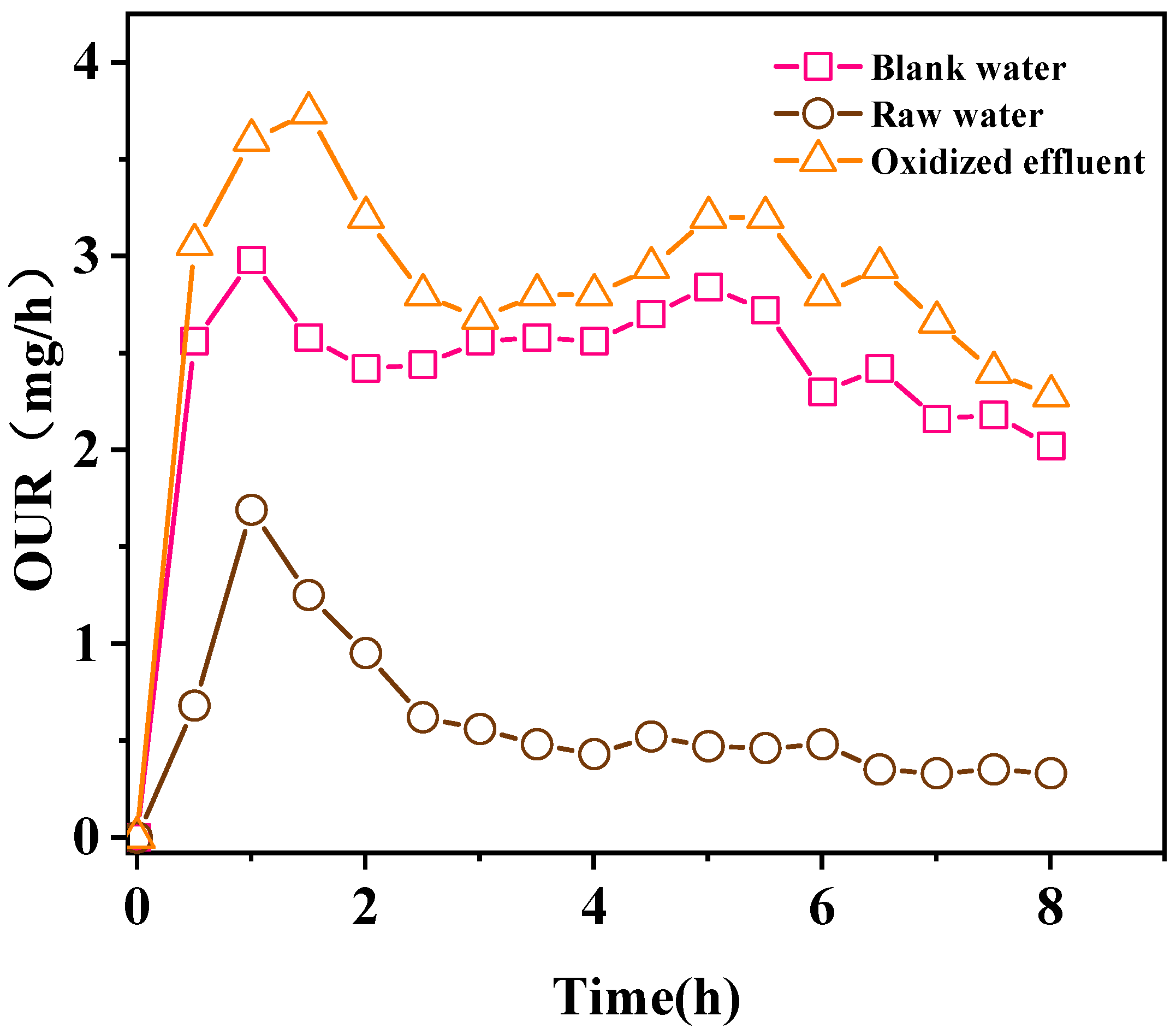
4.1. Biodegradability

Change in biodegradability before and after wastewater purification is very important for actual water treatment. First, BOD5/COD before and after wastewater purification in the UV-CWPO system was tested (Figure 16). In general, the greater the BOD5/COD value is, the better the biodegradability of wastewater is. The wastewater is generally considered to be biodegradable when BOD5/COD > 0.3. The biodegradability of the concentrated liquid of coal chemical wastewater membrane before oxidation was very poor. The BOD5/COD was only 0.02 after five days of biochemical cultivation, indicating that wastewater before oxidation treatment could not be directly treated in the biochemical unit. The biodegradability of wastewater purified by this system was greatly improved. The BOD5/COD of the wastewater reached 0.412 after five days of biochemical culture, and the biodegradability was greatly improved. After oxidation, the large molecular organic matter and toxic and harmful components in wastewater were greatly degraded and transformed into small molecular substances that can be biodegraded [38]. Therefore, wastewater oxidized by UV-CWPO can be treated in the biochemical unit.

4.2. Biological Toxicity Analysis

The biological toxicity of wastewater before and after treatment was determined by measuring the effect of wastewater on the respiration rate of activated sludge. Figure 17 shows the oxygen consumption rate (OUR) of the sample (oxygen mass consumed per unit time). When the reaction lasted for 8 h, the OUR of blank water sample was 2.02 mg/h, the OUR of raw water was 0.33 mg/h, and the OUR of the effluent was 2.28 mg/h. The OUR of water oxidized by the UV-CWPO system was higher than that of the blank water sample. The OUR of the raw water was lower than that of the blank water sample. This finding indicated that the concentrated liquid of coal chemical wastewater membrane before oxidation had serious inhibitory effect on the respiration rate of activated sludge. However, the oxidized water sample promoted the respiration rate of activated sludge, confirming that the oxidized water sample is easily degraded by activated sludge [39].
The inhibition rates of water samples before and after oxidation treatment were calculated relative to the blank samples, and the toxicity of wastewater was classified accordingly (Table 3). The water sample after oxidation treatment changed from the original highly toxic to non-toxic. Hence, the oxidized effluent can enter into the biochemical unit for treatment.

5. Conclusions

In this study, supported perovskite catalyst LaCoO3/X was prepared by two steps (sol–gel method and impregnation). The best catalyst LaCoO3/CeO2 was selected based on macro catalyst performance test and micro characterization analysis. The optimal preparation conditions were established (calcination temperature of 800 °C, calcination time of 8 h). The overall crystal structure of LaCoO3/CeO2 was clear, and the composite metal oxide LaCoO3 with standard perovskite structure was well distributed on the surface of the CeO2 carrier. LaCoO3/CeO2 was used as the catalyst in the UV-CWPO system to participate in the purification of coal chemical wastewater membrane concentrate. Under the best process conditions, i.e., pH of 3, reaction time of 60 min, H2O2 dosage of 40 mM, reaction temperature of 120 °C, reaction pressure of 0.5 MPa, and catalyst dosage of 1 g/L, the removal efficiency of COD, TOC, and UV254 reached 89.7%, 84.6%, and 98.1%, respectively. In addition, the removal efficiency of COD, TOC, and UV254 still reached 88.7%, 82.8%, and 96.3% after seven cycles of degradation, which were not significantly lower than those at the first use. Apparently, the prepared LaCoO3/CeO2 catalyst showed desirable reusability and stability. The biodegradability analysis showed that the BOD5/COD of wastewater treated by the UV-CWPO system increased from 0.02 to 0.412. The toxicity analysis indicated that the water sample after oxidation changed from the original highly toxic to non-toxic, and the oxidized effluent was suitable for subsequent biochemical units. Hence, the supported perovskite catalyst LaCoO3/CeO2 is a pure perovskite catalyst with orthogonal crystal form and has a good application prospect for treating concentrated liquid of a coal chemical wastewater membrane in a UV-CWPO system.

Author Contributions

Methodology, W.Z. and Z.L. (Zhenxue Liu); formal analysis, P.C.; investigation, G.Z.; writing—original draft preparation, W.Z. and Z.L. (Zhenxue Liu); writing—review and editing, Z.L. (Zhiying Liu); funding acquisition, Z.L. (Zhiying Liu) and Y.X. All authors have read and agreed to the published version of the manuscript.

Funding

This research was funded by National Key Research and Development Program of China (grant No.2017YFB0602500).

Institutional Review Board Statement

Not applicable.

Informed Consent Statement

Not applicable.

Data Availability Statement

Not applicable.

Conflicts of Interest

The authors declare no conflict of interest.

References

  1. Zhao, D.; Lun, W.; Wei, J. Discussion on wastewater treatment process of coal chemical industry. In IOP Conference Series: Earth and Environmental Science; IOP Publishing: Bristol, UK, 2017; Volume 100, p. 012067. [Google Scholar]
  2. Ma, H.; Wang, H.; Tian, C.; Wang, L.; Yuan, W.; Qi, Y.; Ma, H.; Chao, Z.; Lv, W. An integrated membrane-and thermal-based system for coal chemical wastewater treatment with near-zero liquid discharge. J. Clean. Prod. 2021, 291, 125842. [Google Scholar] [CrossRef]
  3. Zhang, L.; Li, A.; Lu, Y.; Yan, L.; Zhong, S.; Deng, C. Characterization and removal of dissolved organic matter (DOM) from landfill leachate rejected by nanofiltration. Waste Manag. 2009, 29, 1035–1040. [Google Scholar] [CrossRef]
  4. Tu, S.; Zhu, X.; Du, J.; Liu, T.; Liang, H.; Hong, X. Degradation of Reactive Brilliant Red X-3B by UV-CWPO process with Cu-Zn-Ce catalys. Acta Sci. Circumstantia 2014, 34, 1696–1704. [Google Scholar]
  5. Garcia-Costa, A.L.; Silveira, J.E.; Zazo, J.A.; Dionysiou, D.D.; Casas, J.A. Graphite as catalyst for UV-A LED assisted catalytic wet peroxide oxidation of ibuprofen and diclofenac. Chem. Eng. J. Adv. 2021, 6, 100090. [Google Scholar] [CrossRef]
  6. Garcia-Muñoz, P.; Lefevre, C.; Robert, D.; Keller, N. Ti-substituted LaFeO3 perovskite as photoassisted CWPO catalyst for water treatment. Appl. Catal. B Environ. 2019, 248, 120–128. [Google Scholar] [CrossRef]
  7. Zazo, J.A.; Pliego, G.; García-Muñoz, P.; Casas, J.A.; Rodriguez, J.J. UV-LED assisted catalytic wet peroxide oxidation with a Fe (II)-Fe (III)/activated carbon catalyst. Appl. Catal. B Environ. 2016, 192, 350–356. [Google Scholar] [CrossRef]
  8. Garcia-Costa, A.L.; Sarabia, A.; Zazo, J.A.; Casas, J.A. UV-assisted Catalytic Wet Peroxide Oxidation and adsorption as efficient process for arsenic removal in groundwater. Catal. Today 2021, 361, 176–182. [Google Scholar] [CrossRef]
  9. Qin, Y.; Shen, F.; Zhu, T.; Hong, W.; Liu, X. Catalytic oxidation of ethyl acetate over LaBO3 (B = Co, Mn, Ni, Fe) perovskites supported silver catalysts. RSC Adv. 2018, 8, 33425–33431. [Google Scholar] [CrossRef] [Green Version]
  10. Hou, X.; Ren, J.; Li, F.; Ma, C.; Zhang, X.; Feng, H. Research progress of perovskite materials as catalysts. In IOP Conference Series: Earth and Environmental Science; IOP Publishing: Bristol, UK, 2019; Volume 295, p. 032020. [Google Scholar]
  11. Dukkanci, M. Degradation of bisphenol-a using a sonophoto Fenton-like hybrid process over a LaFeO3 perovskite catalyst and a comparison of its activity with that of a TiO2 photocatalyst. Turk. J. Chem. 2016, 40, 784–801. [Google Scholar] [CrossRef]
  12. Taran, O.P.; Ayusheev, A.B.; Ogorodnikova, O.L.; Prosvirin, I.P.; Isupova, L.A.; Parmon, V.N. Perovskite-like catalysts LaBO3 (B = Cu, Fe, Mn, Co, Ni) for wet peroxide oxidation of phenol. Appl. Catal. B Environ. 2016, 180, 86–93. [Google Scholar] [CrossRef]
  13. Hsu, Y.C.; Chang, S.H.; Chung, W.C.; Chang, M.B. Photocatalytic removal of trichloroethylene from water with LaFeO3. Environ. Sci. Pollut. Res. 2019, 26, 26276–26285. [Google Scholar] [CrossRef]
  14. Palas, B.; Ersöz, G.; Atalay, S. Catalytic wet air oxidation of Reactive Black 5 in the presence of LaNiO3 perovskite catalyst as a green process for azo dye removal. Chemosphere 2018, 209, 823–830. [Google Scholar] [CrossRef] [PubMed]
  15. Bhattar, S.; Abedin, M.A.; Kanitkar, S.; Spivey, J.J. A review on dry reforming of methane over perovskite derived catalysts. Catal. Today 2020, 365, 2–23. [Google Scholar] [CrossRef]
  16. Liu, G.; Wang, J.M. Effects of Nano-Copper(II) Oxide and Nano-Magnesium Oxide Particles on Activated Sludge. Water Environ. Res. 2012, 84, 569–576. [Google Scholar] [CrossRef]
  17. Sudhakaran, M.S.P.; Hossain, M.; Gnanasekaran, G.; Mok, Y.S. Dry reforming of propane over γ-Al2O3 and nickel foam supported novel SrNiO3 perovskite catalyst. Catalysts 2019, 9, 68. [Google Scholar]
  18. Solís, R.R.; Rivas, F.J.; Gimeno, O.; Pérez-Bote, J.L. Synergism between peroxymonosulfate and LaCoO3-TiO2 photocatalysis for oxidation of herbicides. Oper. Var. Catal. Charact. Assess. J. Chem. Technol. Biotechnol. 2017, 92, 2159–2170. [Google Scholar] [CrossRef]
  19. Hammouda, S.B.; Zhao, F.; Safaei, Z.; Babu, I.; Ramasamy, D.L.; Sillanpää, M. Reactivity of novel Ceria–Perovskite composites CeO2-LaMO3 (MCu, Fe) in the catalytic wet peroxidative oxidation of the new emergent pollutant ‘Bisphenol F’: Characterization, kinetic and mechanism studies. Appl. Catal. B Environ. 2017, 218, 119–136. [Google Scholar] [CrossRef]
  20. Wang, X.; Zuo, J.; Luo, Y.; Jiang, L. New route to CeO2/LaCoO3 with high oxygen mobility for total benzene oxidation. Appl. Surf. Sci. 2017, 396, 95–101. [Google Scholar] [CrossRef] [Green Version]
  21. Yang, X.; Gao, Q.; Zhao, Z.; Guo, Y.; Guo, Y.; Wang, L.; Wang, Y.; Zhan, W. Surface tuning of noble metal doped perovskite oxide by synergistic effect of thermal treatment and acid etching: A new path to high-performance catalysts for methane combustion. Appl. Catal. B Environ. 2018, 239, 373–382. [Google Scholar] [CrossRef]
  22. Wang, S.; Xu, X.; Zhu, J.; Tang, D.; Zhao, Z. Effect of preparation method on physicochemical properties and catalytic performances of LaCoO3 perovskite for CO oxidation. J. Rare Earths 2019, 37, 970–977. [Google Scholar] [CrossRef]
  23. Ruder, H. Synthesis of LaCoO3 powder by a combined mechanical/thermal process. Z. Nat. B 2018, 73, 719–724. [Google Scholar]
  24. Tepech-Carrillo, L.; Escobedo-Morales, A.; Perez-Centeno, A.; Chigo-Anota, E.; Sanchez-Ramirez, J.F.; Lopez-Apreza, E.; Gutierrez-Gutierrez, J. Preparation of nanosized LaCoO3 through calcination of a hydrothermally synthesized precursor. J. Nanomater. 2016, 2016, 6917950. [Google Scholar] [CrossRef] [Green Version]
  25. Sun, J.; Zhao, Z.; Li, Y.; Yu, X.; Zhao, L.; Li, J.; Wei, Y.; Liu, J. Synthesis and catalytic performance of macroporous La1-xCexCoO3 perovskite oxide catalysts with high oxygen mobility for catalytic combustion of soot. J. Rare Earths 2020, 38, 584–593. [Google Scholar] [CrossRef]
  26. Alifanti, M.; Blangenois, N.; Florea, M.; Delmon, B. Supported Co-based perovskites as catalysts for total oxidation of methane. Appl. Catal. A Gen. 2005, 280, 255–265. [Google Scholar] [CrossRef]
  27. Yang, Z.C.; Yu, A.Q.; Shan, C.; Gao, G.D.; Pan, B.C. Enhanced Fe(III)-mediated Fenton oxidation of atrazine in the presence of functionalized multi-walled carbon nanotubes. Water Res. 2018, 137, 37–46. [Google Scholar] [CrossRef] [PubMed]
  28. Chen, S.X.; Wang, Y.; Jia, A.P.; Liu, H.H.; Luo, M.F.; Lu, J.Q. Enhanced activity for catalytic oxidation of 1, 2-dichloroethane over Al-substituted LaMnO3 perovskite catalysts. Appl. Surf. Sci. 2014, 307, 178–188. [Google Scholar] [CrossRef]
  29. Liang, H.; Mou, Y.; Zhang, H.; Li, S.; Yao, C.; Yu, X. Sulfur resistance and soot combustion for La0.8K0.2Co1−yMnyO3 catalyst. Catal. Today 2017, 281, 477–481. [Google Scholar] [CrossRef]
  30. Li, X.; Gao, H. Influence of Ce doping on catalytic oxidation of NO on LaCoO3 (011) surface: A DFT study. Appl. Surf. Sci. 2020, 499, 143866. [Google Scholar] [CrossRef]
  31. Guo, Y.Q.; Yin, Y.M.; Tong, Z.; Yin, J.W.; Xiong, M.W.; Ma, Z.F. Impact of synthesis technique on the structure and electrochemical characteristics of Pr0.6Sr0.4Co0.2Fe0.8O3(PSCF) cathode material. Solid State Ion. 2011, 193, 18–22. [Google Scholar] [CrossRef]
  32. Wang, Y.; Zheng, Y.; Wang, H.; Li, K.; Zhu, X.; Wei, Y.; Wang, Y.; Jiang, L.; Tian, D. Enhanced activity for CO preferential oxidation via the CeO2-LaCoO3 interaction. Ind. Eng. Chem. Res 2019, 58, 4710. [Google Scholar] [CrossRef] [Green Version]
  33. Afzal, S.; Quan, X.; Zhang, J. High surface area mesoporous nanocast LaMO3(M=Mn, Fe) perovskites for efficient catalytic ozonation and an insight into probable catalytic mechanism. Appl. Catal. B Environ. 2017, 206, 692–703. [Google Scholar] [CrossRef]
  34. Li, W.; Qiang, Z.; Zhang, T.; Cao, F. Kinetics and mechanism of pyruvic acid degradation by ozone in thepresence of PdO/CeO2. Appl. Catal. B Environ. 2012, 113, 290–295. [Google Scholar] [CrossRef]
  35. Pajić, N.D.; Djinović, P.; Dražić, G.; Grdadolnik, J.; Šket, P.; Cerkovnik, J.; Pintar, A. Structural stabilization and characterization of active peroxo species on TiO2-nanotube based materials in mild catalytic wet peroxide oxidation process. Appl. Catal. A Gen. 2018, 562, 276–283. [Google Scholar] [CrossRef]
  36. Bulca, Ö.; Palas, B.; Atalay, S.; Ersöz, G. Performance investigation of the hybrid methods of adsorption or catalytic wet air oxidation subsequent to electrocoagulation in treatment of real textile wastewater and kinetic modelling. J. Water Process Eng. 2021, 40, 101821. [Google Scholar] [CrossRef]
  37. Zhang, J.; Tan, D.; Meng, Q.; Weng, X.; Wu, Z. Structural modification of LaCoO3 perovskite for oxidation reactions: The synergistic effect of Ca2+ and Mg2+ co-substitution on phase formation and catalytic performance. Appl. Catal. B Environ. 2015, 172, 18–26. [Google Scholar] [CrossRef]
  38. Samoila, P.; Cojocaru, C.; Mahu, E.; Ignat, M.; Harabagiu, V. Boosting catalytic wet-peroxide-oxidation performances of cobalt ferrite by doping with lanthanides for organic pollutants degradation. J. Environ. Chem. Eng. 2021, 9, 104961. [Google Scholar] [CrossRef]
  39. Brar, S.K.; Verma, M.; Tyagi, R.D.; Surampalli, R.Y. Engineered nanoparticles in wastewater and wastewater sludge–Evidence and impacts. Waste Manag. 2010, 30, 504–520. [Google Scholar] [CrossRef]
Figure 1. Schematic diagram of the laboratory UV-CWPO system. (① Intake valve, ② Exhaust valve, ③ Pressure gauge, ④ Photochemical high pressure reactor, ⑤ MRSC-TFM control system, ⑥ 30W UV-deuterium lamp source).
Ijerph 18 04906 g001
Figure 2. Effect of catalyst support on catalytic effect. (Catalyst preparation conditions: calcination temperature = 800 °C, calcination time = 8 h; Reaction conditions: LaCoO3/CeO2 = 0.8 g/L, H2O2 = 40 mM, 120 °C, 1 MPa, 60 min).
Ijerph 18 04906 g002
Figure 3. Effect of calcination temperature on catalytic effect. (Catalyst preparation conditions: catalyst support, CeO2, calcination time = 8 h; Reaction conditions: LaCoO3/CeO2 = 0.8 g/L, H2O2 = 40 mM, 120 °C, 1 MPa, 60 min).
Ijerph 18 04906 g003
Figure 4. Effect of calcination time on catalytic effect. (Catalyst preparation conditions: catalyst support, CeO2, calcination temperature = 800 °C; Reaction conditions: LaCoO3/CeO2 = 0.8 g/L, H2O2 = 40 mM, 120 °C, 1 MPa, 60 min).
Ijerph 18 04906 g004
Figure 5. XRD patterns of LaCoO3 catalysts with different supports. (Catalyst preparation conditions: calcination temperature = 800 °C, calcination time = 8 h).
Ijerph 18 04906 g005
Figure 6. SEM images of LaCoO3/CeO2 catalyst. (a). SEM of 500 μm; (b). SEM of 50 μm; (c). SEM of 5 μm.
Ijerph 18 04906 g006
Figure 7. XPS spectra of La3d of LaCoO3 (a) and LaCoO3/CeO2 (b).
Ijerph 18 04906 g007
Figure 8. XPS spectra of Co 2p of LaCoO3 (a) and LaCoO3/CeO2 (b).
Ijerph 18 04906 g008
Figure 9. XPS spectra of O1s of LaCoO3 (a) and LaCoO3/CeO2 (b).
Ijerph 18 04906 g009
Figure 10. Comparison to different reaction systems. (Reaction conditions: LaCoO3/CeO2 = 1 g/L, H2O2 = 40 mM, 120 °C, 0.5 MPa).
Ijerph 18 04906 g010
Figure 11. Effect of H2O2 dosage on oxidation. (Reaction conditions: LaCoO3/CeO2 = 0.8 g/L, 120 °C, 1 MPa, 60 min).
Ijerph 18 04906 g011
Figure 12. Effect of reaction temperature on oxidation. (Reaction conditions: LaCoO3/CeO2 = 0.8 g/L, H2O2 = 40 mM, 1 MPa, 60 min).
Ijerph 18 04906 g012
Figure 13. Effect of reaction pressure on oxidation. (Reaction conditions: LaCoO3/CeO2 = 0.8 g/L, H2O2 = 40 mM, 120 °C, 60 min).
Ijerph 18 04906 g013
Figure 14. Effect of catalyst dosage on oxidation. (Reaction conditions: H2O2 = 40 mM, 120 °C, 0.5 MPa, 60 min).
Ijerph 18 04906 g014
Figure 15. Effect of repeated use of catalyst on catalysis. (Reaction conditions: LaCoO3/CeO2 = 1 g/L, H2O2 = 40 mM, 120 °C, 0.5 MPa, 60 min).
Ijerph 18 04906 g015
Figure 16. Comparison of BOD5/COD before and after oxidation.
Ijerph 18 04906 g016
Figure 17. Changes in oxygen consumption rates in water samples measured and blank control samples.
Ijerph 18 04906 g017
Table 1. BET surface area and pore structure of LaCoO3 catalysts with different supports.
CatalystSpecific Surface Area (m2/g)Pore Volume (cm3/g)Pore Diameter (nm)
LaCoO32.67490.00634.9501
LaCoO3/CeO213.07290.05244.0569
Table 2. Ratio of Co3+ and Co2+ and OL and OS of LaCoO3 and LaCoO3/CeO2.
CatalystCo3+/Co2+OL/OS
LaCoO31.880.80
LaCoO3/CeO21.151.48
Table 3. Results of toxicity in water samples.
SampleRespiratory Depression RateToxicity
Raw water83.66%High toxic
Oxidation dischargeNo inhibitionNon-toxic
Publisher’s Note: MDPI stays neutral with regard to jurisdictional claims in published maps and institutional affiliations.

