Article

A Control Strategy of Modular Multilevel Converter with Integrated Battery Energy Storage System Based on Battery Side Capacitor Voltage Control

State Key Laboratory of Advanced Electromagnetic Engineering and Technology, Huazhong University of Science and Technology, Wuhan 430074, China
*
Author to whom correspondence should be addressed.
Submission received: 17 April 2019 / Revised: 24 May 2019 / Accepted: 3 June 2019 / Published: 5 June 2019
(This article belongs to the Special Issue Power Electronics Applications in Renewable Energy Systems)

Abstract

:
A modular multilevel converter with an integrated battery energy storage system (MMC-BESS) has been proposed for high-voltage applications for large-scale renewable energy resources. As capacitor voltage balance is key to the normal operation of the system, the conventional control strategy for the MMC can be significantly simplified by controlling the individual capacitor voltage through a battery side converter in the MMC-BESS. However, the control strategy of the MMC-BESS under rectifier mode operation has not yet been addressed, where the conventional control strategy cannot be directly employed due to the additional power flow of batteries. For this defect, the rectifier mode operation of the MMC-BESS based on a battery side capacitor voltage control was analyzed in this paper, proposing a control strategy for this application scenario according to the equivalent circuit of MMC-BESS, avoiding passive impact on the state-of-charge (SOC) equalization of batteries. Furthermore, the implementation of a battery side converter control is proposed by simplifying the capacitor voltage filter scheme within phase arm, which enhances its performance and facilitates the realization of control strategy. Finally, simulation and experimental results validate the feasibility and effectiveness of the proposed control strategy.

1. Introduction

In recent years, the grid-connected applications of large-scale renewable energy resources have gradually become a trend, presenting new challenges to the power electronics converters applied in high-voltage and high-power fields [1]. Multilevel topologies can reduce the requirement of voltage rate of switching devices, achieving higher voltage levels [2]. Among existing multilevel topologies, a modular multilevel converter (MMC) is considered the most promising topology and has been extensively studied in the past decade [3,4,5]. Modular multilevel converters share the common advantages of multilevel converters, such as low harmonic content of output voltage and small voltage stress of switching devices. Compared with the cascaded H-bridge (CHB) topology with the modular structure, the MMC topology has only half of the arm current at the same power rate. There also exists a common DC-link in the MMC topology which is unavailable in CHB topology [6]. Based on this consideration, MMCs can be utilized as AC/DC interlinking converters in medium- and high-voltage renewable energy generation systems, e.g., offshore wind farm generation systems [7] and microgrids [8], as shown in Figure 1.
Due to the characteristics of randomness and intermittency of renewable energy resources, the normal operation and power quality of the power system would be remarkably affected, reducing the voltage and frequency stability. To attenuate the passive impact caused by renewable energy resources, a battery energy storage system (BESS) is a reasonable and efficient solution for grid-connected renewable energy generation systems, as shown in Figure 1a,b. Recently, to simplify the configuration of BESS in the scenarios of MMC-based applications, the MMC with integrated BESS is proposed by combining the MMC and BESS together [9]. The extra power conversion system (PCS) of BESS can be saved by this combination. In this paper, this topology is abbreviated as the MMC-BESS. The integration was implemented by inserting battery cells into each submodule (SM) of MMC directly or through a DC/DC interface [10,11]. Due to this distributed integration mode of BESS, the state-of-charge (SOC) equalization of each battery was facilitated, improving the effective utilization rate of BESS compared with the centralized scheme at the DC-link of MMC [12].
In addition to the inherent advantages provided by BESS for the power system, the integration scheme of batteries through DC/DC interfaces provided and additional degree of freedom (DOF) to the system control strategy. As the capacitor voltage balancing control was significant to conventional MMCs, the cascaded control structure for balancing the capacitor voltage in the phase-, arm- and individual SM-level is reported in Reference [13], which was consequently employed in the MMC-BESS in Reference [14]. Nevertheless, with the additional DOF provided by batteries in the MMC-BESS, the capacitor voltage balancing control can be significantly simplified through battery side control, which makes individual SM capacitor behave as a voltage source to the MMC, avoiding the cascaded control structure and relatively complicated capacitor voltage balancing algorithms introduced in Reference [4]. It is worth noting that the premise of the battery side capacitor voltage control was that each SM must contain a battery module, otherwise the capacitor voltage would be incontrollable.
Based on the battery side capacitor voltage control, some studies have been reported. In Reference [11], the control strategy of a MMC-BESS operating as an inverter was researched, proposing the three-level SOC equalization control structure. In Reference [15], the SOC equalization of MMC-BESS considering the capacity inconsistency of batteries was proposed. In References [10,16], the MMC-BESS was applied in battery electric vehicles and the efficiency of this topology was assessed. Furthermore, the control strategy of MMC-BESS under AC and DC fault has been studies in Reference [17], realizing SOC equalization under fault conditions. Nevertheless, the current research is not deep enough, as the existing control strategies merely focus on the inverter mode operation of MMC-BESS. Usually, in MMC-based multi-terminal DC transmission system (e.g., Figure 1a), one of the MMCs must be responsible for DC-link voltage control while the other MMCs should be responsible for power control [18]. Similarly, in Figure 1b, the interlinking MMC should take the DC-link voltage as the control objective. Accordingly, the rectifier mode operation of MMC-BESS is required. However, the DC-link voltage control structure in conventional MMCs [18] cannot be directly employed in the MMC-BESS due to the additional power flow of BESS, which has not been investigated in detail in the current literature. As the battery side converter is employed to control the capacitor voltage, the SOC equalization must be achieved by MMC side control. Hence, the combination of SOC equalization and DC-link voltage control is mandatory in the MMC-BESS. Besides, as the capacitor voltage is controlled by battery side converter, the performance of the system would be greatly dependent on the battery side control strategy. As the individual capacitor voltage contains ripples at multiple frequencies while the battery current is expected to be pure DC component, the battery side control strategy should be investigated to ensure the performance both in a steady and dynamic state.
In this paper, based on battery side capacitor voltage control, the control strategy of rectifier mode operation was analyzed according to the equivalent circuit of the MMC-BESS. The DC-link voltage control was combined with the SOC equalization control, different from the control strategy applied in conventional MMCs. Furthermore, a simplified capacitor voltage filter scheme was proposed in this paper to facilitate the implementation of battery side control strategy.
The rest of this paper is organized as follows. Section 2 describes the basic configuration and the equivalent circuit of the MMC-BESS. Then the control strategy of rectifier mode operation of MMC-BESS is proposed in Section 3. To enhance the performance of battery side control strategy, a simplified capacitor voltage filter scheme is proposed in Section 4. Finally, the effectiveness and feasibility of the proposed control strategy of rectifier mode operation are validated by simulations and experimental results in Section 5.

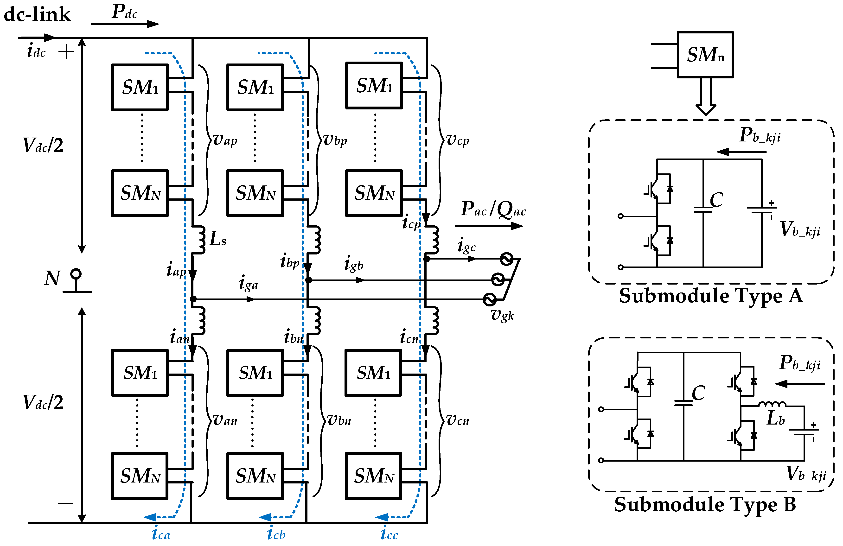
2. Mathematic Model and Principles of MMC-BESS

The topology of three-phase MMC-BESS is shown in Figure 2. Each phase leg is comprised of 2N SMs in series, where the midpoint connected to the AC side divides a phase leg into two phase arms. Here, N represents the number of SMs in series per phase arm. Throughout this paper, the subscript k = (a, b, c) refers to the individual phase; j = (p, n) refers to the upper and lower arms; i = (1, 2 … N) refers to the individual SM within phase arm. The DC-link voltage and grid phase-voltage are denoted as Vdc and vgk, respectively. Each phase arm contains an arm inductor Ls with losses denoted by Rs (not shown in the figure). In general, the topology of the MMC-BESS is consistent with conventional MMCs. The main difference locates on the topology of SM. In addition to the half-bridge structure with the SM capacitor, BESS is integrated into each SM in different ways, which forms two types of SM as shown in Figure 2. For SM type A, the battery is directly connected to the terminals of individual SM capacitors; for SM type B, the battery is connected to individual SM capacitors through a DC/DC interface, while Lb is the inductor of this DC/DC converter. In the authors’ view, SM type A compels the capacitor voltage to follow the battery voltage, inducing the power fluctuation caused by ripples in capacitor voltage into the battery which would impair the health or shorten the lifespan of an individual battery. On the contrary, the DC/DC interface in SM type B can decouple the battery side and MMC side through the SM capacitor, preventing the ripples from flowing into the battery through an appropriate control strategy, but it would comparatively degrade the power conversion efficiency due to the DC/DC interface. Nevertheless, the DC/DC interface provides a degree of freedom for the system control which SM type A does not, and the requirement of the terminal voltage of the battery module can be greatly lower than the rated capacitor voltage. Besides, it would not affect the original power conversion efficiency between AC and DC side of MMC itself. Hence, SM type B was employed in this paper. It should be noted that the topology of the DC/DC interface in SM type B was not restricted to a non-isolated buck–boost converter as shown in Figure 2, which was adopted in this paper for the convenience and simplicity.
The MMC-BESS can be modelled identically to a conventional MMC as follows [19]:
{ v s k = R s 2 i g k + L s 2 d i g k d t + v g k v c k = L s d i c k d t + R s i c k
where vsk is the voltage required to drive the AC output current igk, and vck is the voltage required to drive the difference current ick. The difference current ick is a circulating current flowing through upper and lower arms within one phase simultaneously, which would not affect the AC side.
The upper and lower arm currents were composed of a circulating current and a half of AC output current as [19]:
{ i k p = i g k 2 + i c k i k n = i g k 2 + i c k
The difference current can contain component at any frequency, but only DC and fundamental frequency components are necessary for power conversion in the MMC-BESS [14]. Thus, assuming:
i c k = I d c k + I 1 k cos ( ω t + φ 1 k )
where Idck denotes the DC component; I1k and φ1k are the amplitude and angle of fundamental component in phase k; ω is the fundamental angular frequency of AC side.
By applying Kirchhoff’s Voltage Laws(KVL) to Figure 2, the output voltages of the upper and lower arms can be yielded as
{ v k p = V d c 2 v s k v c k v k n = V d c 2 + v s k v c k
Due to the battery power existing in the system, the following relationship is satisfied throughout neglecting losses:
P a c = P d c + k a , b , c j p , n i = 1 N P b _ k j i
where Pac and Pdc are total active powers of the AC and DC side, respectively, while Pb_kji is the battery power of individual SM. Note that the power directions are all in accordance with Figure 2 in this paper. To compensate or absorb power fluctuations of the AC or DC side of the MMC-BESS, the individual battery would discharge when Pb_kji > 0, vice versa.
Assuming the grid voltage and arm current of phase k in time domain are expressed as:
{ v g k = V g k cos ω t i g k = I g k cos ( ω t + φ k )
where Igk and φk are amplitude and angle of grid current; Vgk is the amplitude of the grid voltage. Substituting Equation (6) into the individual arm voltage (4), then multiplying it with the arm current (2) and taking battery powers into account, the total battery power of each arm over one fundamental period can be derived as
{ i = 1 N P b _ k p i = P k p = ω 2 π t t + 2 π ω v k p i k p = 1 2 P d c k 1 2 P a c k + P d i f f k i = 1 N P b _ k n i = P k n = ω 2 π t t + 2 π ω v k n i k n = 1 2 P d c k 1 2 P a c k P d i f f k
where
{ P d c k = V d c I d c k P a c k = 1 2 V g k I g k cos φ k P d i f f k = 1 2 ( i = 1 N P b _ k n i i = 1 N P b _ k p i ) = 1 2 V g I 1 k cos φ 1 k
Here, Pdiffk is defined as the difference power between upper and lower arms of phase k. According to Equation (7), the power flows of the three-phase MMC-BESS can be shown as Figure 3. It can be concluded that the DC circulating current is the carrier of DC power between the MMC-BESS and DC-link; the fundamental frequency circulating current transfers power between the upper and lower arms within one phase; the fundamental frequency grid current transfers active and reactive power between the MMC-BESS and the AC grid. Therefore, by regulating these components in corresponding currents, the power flows among batteries, DC-link, and AC grid can be controlled as the system requires.
If the individual capacitor voltage is controlled by MMC side, the cascaded capacitor voltage control strategy would be employed at the DC side [14], and the individual battery power would be directly controlled by battery side converter, which makes it behave as a constant power load (CPL) to the corresponding SM. On the contrary, if the battery side converter is utilized to control the individual capacitor voltage, the capacitor would behave as a voltage source to the MMC side. Consequently, the cascaded capacitor voltage balancing controls in conventional MMCs can be avoided. Nevertheless, due to the existence of the additional power flow of BESS, when the DC-link voltage is required to be controlled by the MMC-BESS itself in rectifier mode operation, the original control strategy in conventional MMCs (outer-loop DC-link voltage control and inner-loop active grid current control [18]) would be invalid because this manner would lead to the uncertainty of battery power, bringing instability to the system operation. In essence, the AC power and DC power are not strictly equal to each other in the MMC-BESS compared with conventional MMCs. The DC-link voltage is not only decided by the active grid current at AC side, but also the battery power each phase. Hence, to make the batter-side-based capacitor voltage control effective in the rectifier mode, the control strategy will be proposed in the following section.

3. Control Strategy of Rectifier Mode Operation of MMC-BESS

3.1. SOC Equalization of MMC-BESS

As an important function of a PCS, SOC equalization of batteries must be achieved during operation of the MMC-BESS. Based on the structure of the MMC-BESS, the SOC equalization is divided into three levels: among three phases, between upper and lower arms, and among SMs within one arm. The definition of SOC is expressed as
S O C = Storaged   Charges Nominal   Capacity × 100 %
The SOC of individual battery can be established as
S O C k j i ( t ) = S O C k j i ( t 0 ) + 1 E b _ k j i t 0 t P b _ k j i d t
where Pb_kji is the individual battery power; Eb_kji is the nominal energy of individual battery given by the production of battery voltage and its capacity. According to Equation (10), the SOC of individual battery can be controlled through the direct regulation of corresponding battery power. Since Eb_kji may be different in individual SM due to the age of battery, the SOC equalization should take the capacity of individual battery into consideration. According to the research in Reference [15], battery capacity should be employed to produce the coefficient for corresponding SOC equalization control. For the sake of simplicity, it is assumed that all batteries are of the same capacity, which would not affect the following investigations in this paper.
The required power adjustments are generated through closed-loop controls of average SOC in corresponding levels as shown in Figure 4, where Kph, Karm, and KSM are the coefficients of SOC equalization controller each level. Since the battery side converters are employed to control the capacitor voltages, the SOC equalization must be achieved by MMC side control. Hence, the SOC equalizations are realized by adjusting the modulation waveforms at MMC side according to the power differences ΔPb_k, ΔPb_kj, and ΔPb_kji in Figure 4.

3.1.1. SOC Equalization among Three Phases

Seen from Figure 3 and Equation (7), the total battery power within one phase is composed by DC power and AC power, so the battery power can be regulated by these two components. Nevertheless, due to the power control requirement at AC side, the AC powers must be symmetric in three phases under a balanced AC grid. Hence, to equalize the SOCs among phases, DC power should be regulated at each phase.
When the MMC-BESS operates as an inverter, the DC-link voltage is fixed to the system and the DC side would be controlled as the current sources each phase independently [17]. However, when the MMC-BESS operates as a rectifier, this manner would be invalid because the DC-link must be controlled as a voltage source by the DC side control of MMC-BESS. With the individual capacitor voltage controlled by battery side converter, the DC side equivalent circuit of MMC-BESS can be present as Figure 5. The capacitors behave as a controllable voltage source, then the DC-link voltage should be controlled by three-phase DC circulating current collectively. Therefore, the DC side control is proposed based on this DC side equivalent circuit in this paper as shown in Figure 6.
In Figure 6, the DC-link voltage is regulated by a proportional–integral (PI) controller. The coefficient Ksoc_k is employed to redistribute the DC power among the three phases according to the difference power in Figure 4a as:
K S O C _ k = V d c I d c / 3 + Δ P b _ k V d c I d c
when the SOCs of three phases have been equalized, Ksoc_k would be 1/3 consequently, which means DC power is equally divided by three phases. Through the proposed DC-link voltage control, the DC circulating current reference is generated by each phase.

3.1.2. SOC Equalization between Upper and Lower Arms

According to Equation (8), the fundamental frequency circulating current can transfer power between the upper and lower arms within one phase. With the difference power generated by SOC equalization controller in Figure 4b, the fundamental frequency circulating current reference can be obtained. Due to the demand of preventing fundamental frequency circulating current per phase from flowing into DC-link, the reactive components are injected into the other two phases as [11]:
[ i 1 a r e f i 1 b r e f i 1 c r e f ] = 2 V g [ cos φ 1 3 sin φ 1 3 sin φ 1 3 sin ( φ 2 π 3 ) cos ( φ 2 π 3 ) 1 3 sin ( φ 2 π 3 ) 1 3 sin ( φ + 2 π 3 ) 1 3 sin ( φ + 2 π 3 ) cos ( φ + 2 π 3 ) ] [ P d i f f a r e f P d i f f b r e f P d i f f c r e f ]
where
P d i f f k r e f = Δ P b _ k p Δ P b _ k n 2
Since DC and fundamental frequency components are required to be controlled in the circulating current each phase, a proportional–integral–resonant (PIR) controller tuned at fundamental frequency and double line-frequency was employed to regulate components at different frequencies simultaneously, as shown in Figure 7. In this paper, the reference of double line-frequency component i 2 k r e f was set as zero to reduce the power losses [13].

3.1.3. SOC Equalization among SMs within Phase Arm

Since all SMs within the same phase arm share a common arm current, the individual SM power must be regulated by redistributing the terminal voltage without affecting the output voltage of the whole arm. Based on the former two SOC equalization controls, the total power of the phase arm can be generated as
P b _ k j r e f = P a c P d c 6 Δ P b _ k 2 Δ P b _ k j
Consequently, the individual battery power reference was obtained through the SOC controller in Figure 4c as:
P b _ k j i r e f = P b _ k j r e f N Δ P b _ k j i
Defining the power ratio of individual SM according to the battery power as:
m k j i = P b _ k j i r e f i = 1 N P b _ k j i
By multiplying mkji with the arm voltage reference vkj, the SM power can be regulated according to the SOC equalization control within phase arm. With the constraint as:
i = 1 N m k j i = 1
the output voltage of the whole arm would not be affected by the SOC equalization within phase arm.

3.2. Control Strategy of MMC-BESS Based on Battery Side Capacitor Voltage Control

According to the equivalent circuit in Figure 3, the control strategy of the MMC-BESS mainly consists of three parts: DC side control, AC side control, and battery side control. With the capacitor voltage controlled by the battery side converter, each SM, DC, and AC side control of the MMC are simplified in this paper. As per the analysis in Section 2, when the MMC-BESS operates as a rectifier in multi-terminal MMC-based applications, the output of the DC-link voltage controller cannot be employed as the reference of the active current at the AC side. Hence, the DC-link voltage control was proposed by regulating the DC circulating current at each phase according to the SOC equalization among three phases, as per Figure 6. On the other hand, the AC side should be controlled in a way in which the active and reactive powers are given directly according to the system’s requirement [13]. By doing this, AC power is directly controlled by the reference, DC power is determined by external DC network, and battery power is controlled indirectly by capacitor voltage control.
The overall control strategy of the MMC-BESS based on battery side capacitor voltage control is shown in Figure 8.
The SOC equalization of all three levels are implemented by the MMC side control according to the proposed control strategies in Section 3.1. The common modulation waveform of the individual phase arm is generated by AC and DC side controls of the MMC, then the modulation waveform of individual SMs is generated by the power redistribution ratio according to Equation (16). Finally, carrier phase-shifted pulse-width modulation (CPS-PMW) is utilized to generate the pulse signal for MMC side-switching devices [20]. On the other hand, the implementation of battery side capacitor voltage control will be introduced in the next section.

4. Implementation of Battery Side Control Strategy

The local circuit of the individual bidirectional DC/DC converter with control diagram is shown in Figure 9, where the MMC side is taken as the load for the battery side represented as the current iM_kji. The midpoint voltage of the battery side half-bridge vT-kji is taken as the input of the bidirectional DC/DC converter. In Figure 9, GVR and GCR are voltage and current regulators, respectively; The time delay caused by PWM is defined as Gd, which is treated as 1.5Tsb [21]. Here, Tsb is the switching period of the battery side DC/DC converter.
Although some research on the control strategy of bidirectional DC/DC converters has been published [21,22], the application of MMC-BESS still has special issues which should be investigated. The control targets are the individual capacitor voltage vc_kji with a stable DC component and the battery current ib_kji without a low-frequency AC component. However, the voltage ripples (mainly at fundamental and double-line frequency) caused by operation of the MMC side would bring negative influence to the DC/DC converter control. To eliminate these ripples, the filter block GF is employed as shown in Figure 9, but the type of GF should be discussed. Since moving average filter (MAF) can attenuate components in specific frequencies [23], it is especially suitable for filtering harmonics in capacitor voltage of MMC-BESS. The transfer function of MAF in discrete domain is
G F = 1 N F 1 z N F 1 z 1
where NF is the number of sampling data stored in the digital processor. However, since the switching frequency of an individual DC/DC converter is usually well above the fundamental frequency at the MMC side, it will lead to the requirement of a large amount of data storage space in the DC/DC converter control. For example, for a sampling frequency (equal to the switching frequency of DC/DC converter) fsb = 10 kHz and fundamental frequency of MMC side f = 50 Hz, NF is given by fsb/f = 200. With the increment of the number of SMs in the series per phase arm, the data storage space required by the MAFs would consequently become large-scale. To avoid the defect of large-scale data storage space in this application, a common MAF scheme shared by all SMs per arm is proposed in this paper.
The MMC side current iM_kji in Figure 9 can be expressed as:
{ i M _ k p i = i k p m k p i = ( I g cos ( ω t + φ ) 2 + I d c k + I 1 k cos ( ω t + φ 1 k ) ) ( m d c _ k p i m a c _ k p i cos ω t ) i M _ k n i = i k n m k n i = ( I g cos ( ω t + φ ) 2 + I d c k + I 1 k cos ( ω t + φ 1 k ) ) ( m d c _ k p i + m a c _ k p i cos ω t )
Then the individual capacitor voltage can be derived as:
{ v c _ k p i = 1 C ( i M _ k p i + i B _ k p i ) d t + v c _ k p i _ 0 v c _ k n i = 1 C ( i M _ k n i + i B _ k n i ) d t + v c _ k n i _ 0
where the vc_kpi_0 and vc_kpi_0 are initial voltages of capacitors in the upper and lower arms, respectively. The DC component of the capacitor current must be zero, otherwise the capacitor voltage would be instable with time, which can be deduced as
{ m d c _ k p i I d c k 1 4 m a c _ k p i I g cos φ 1 2 m a c _ k p i I 1 k cos φ 1 k + i B _ k p i = 0 m d c _ k n i I d c k 1 4 m a c _ k n i I g cos φ + 1 2 m a c _ k n i I 1 k cos φ 1 k + i B _ k n i = 0
Substituting Equations (19) and (21) into (20), the average ripples of individual capacitors are derived as:
{ 1 N i = 1 N v ˜ c _ k p i = 1 ω C ( 1 4 I 1 k m a c _ k p sin ( 2 ω t + φ 1 k ) + I 1 k m d c _ k p sin ( ω t + φ 1 k ) 1 8 I g m a c _ k p sin ( 2 ω t + φ ) + 1 2 I g m d c _ k p sin ( ω t + φ ) I d c k m a c _ k p sin ω t ) 1 N i = 1 N v ˜ c _ k n i = 1 ω C ( 1 4 I 1 k m a c _ k n sin ( 2 ω t + φ 1 k ) + I 1 k m d c _ k n sin ( ω t + φ 1 k ) 1 8 I g m a c _ k n sin ( 2 ω t + φ ) 1 2 I g m d c _ k n sin ( ω t + φ ) + I d c k m a c _ k n sin ω t )
Seen from Equations (20) and (22), the battery side current iB_kji affects the DC component in capacitor voltage, while the individual capacitor voltage ripples are mainly decided by the common arm current flowing through all SMs per phase arm. It can be proved by the simulation waveforms in Figure 10, the individual battery power differentiated from each other up to ±40%, and the corresponding capacitor voltage ripples were almost identical due to the common arm current.
Based on the analysis above, an improved control strategy of a battery side DC/DC converter with the data storage space reduction of MAF is proposed in Figure 11. In this scheme, a common MAF was employed to extract the average capacitor voltage ripples of all SMs per phase arm, then the individual capacitor voltage ripples were counteracted by the average capacitor voltage ripples. Through the common MAF, the occupied data storage space can be reduced to 1/N compared with the original scheme implemented in each SM.
On the other hand, since the capacitor voltage was controlled by the individual DC/DC converter, the dynamic response was expected to be fast enough for MMC side power conversion. However, due to the existence of the MAF, the bandwidth of the voltage control loop cannot exceed the cut-off frequency of the MAF, which is unacceptable in application. Seen from Figure 9, the reference of the capacitor voltage was constant during normal operation of the MMC-BESS, hence, the disturbance from the MMC side iM_kji is the exclusive factor that causes the fluctuation of the DC capacitor voltage. To eliminate the load disturbance, the load current feedforward can be implemented. However, the measurement of MMC side load in individual SM would greatly increase the cost of the system, and iM_kji is a current in pulse form which is different from ordinary bidirectional DC/DC converter. Therefore, the load disturbance was mitigated by estimated battery current in this paper as:
I f f _ k j i = 1 v b _ k j i ( 3 v g d i g d / 2 V d c I d c 6 N Δ P b _ k 2 N Δ P b _ k j N Δ P b _ k j i )
This estimated feedforward component was calculated based on the instantaneous power relationship in Equation (5), where the AC and DC powers were derived from measured values instead of the reference values, representing the dynamics of power flows in real time. Then the feedforward component was redistributed into each SM according to the SOC of individual battery. Consequently, the dynamic performance of the individual capacitor voltage control can be significantly improved.
Finally, the improved control strategy in Figure 11 can be simplified as Figure 12 through the block diagram transformation. Dkji is the ratio of capacitor voltage and individual battery voltage. The MAF block in Figure 11 is equivalent to the configuration in individual feedback loop in Figure 12. With this simplified control diagram, the design of controllers of capacitor voltage and battery current is convenient to be implemented using the control system theory.

5. Simulations and Experimental Results

5.1. Simulation Results

The simulation model of the three-phase MMC-BESS is built in MATLAB/Simulink (R2016b, Mathworks, Natick, MA, USA). The main parameters are listed in Table 1. To verify the SOC equalization proposed in this paper, the capacity of individual battery is set as 0.3 Ah, so the SOCs can be equalized rapidly.

5.1.1. Rectifier Mode Operation with Proposed Control Strategy Based on Battery Side Capacitor Voltage Control

The simulation waveforms of rectifier mode operation are shown in Figure 13 and the SOC equalization process is shown in Figure 14. The initial SOCs of all 24 SMs are arbitrarily distributed from 61% to 71%. The AC power increases from 0 to 480 kW through a slope reference, then it is transferred to 320 kW at t = 0.4 s and 640 kW at t = 0.6 s. A 480 kW external DC load is connected to the DC-link at t = 0.1 s. Seen from Figure 13, the AC power is indicated by grid currents in Figure 13a; the DC-link voltage is shown in Figure 13b. With the proposed control strategy for rectifier mode operation of MMC-BESS, the DC-link voltage is controlled to the reference value throughout. The capacitor voltages are shown in Figure 13c utilizing the proposed battery side-based capacitor voltage control strategy. Figure 13d shows the circulating currents of three phases. The DC circulating currents are controlled according to the coefficient in Equation (11) to equalize the SOCs among phases, while the fundamental frequency circulating currents are controlled according to Equation (12) to equalize the SOCs between the upper and lower arms each phase. With the SOCs gradually converging to the same value, the differences among circulating currents in three phases also decrease consequently. The battery currents of four SMs within upper arm of phase A are shown in Figure 13d, where the differences among SMs also decrease gradually during the SOC equalization process. In Figure 14, the SOC equalization of all three levels are illustrated. Figure 14a shows the SOC equalization of all 24 SMs. The SOC equalizations among three phases, between upper and lower arms, and among SMs are shown in Figure 14b–d, respectively. During the rectifier mode operation of MMC-BESS, the simulation results validate the effectiveness of the proposed control strategy based on battery side capacitor voltage control.

5.1.2. Verification of Proposed Battery Side Capacitor Voltage Control Strategy

The verifications of the proposed battery side capacitor voltage control strategy in steady and dynamic state are shown in Figure 15. Figure 15a is implemented without feedforward component of Equation (23), while this feedforward component is employed in Figure 15b,c. The difference of implementation between Figure 15b,c locates on the capacitor voltage filter scheme. The MAF is implemented in each SM capacitor voltage control in Figure 15b while the proposed common MAF scheme within one phase arm is employed in Figure 15c. At t = 0.3 s, the AC power reference is transferred from 480 kW to 960 kW, then at t = 0.6 s, the external DC load is transferred from 480 kW to 960 kW. In transient process, the capacitor voltage variation is up to Δvc1 = −16% and the regulation time of battery current is tr1 = 0.2 s after t = 0.3 s in Figure 15a. While in Figure 15b, with the estimated feedforward component at battery side control, the transient performance is significantly improved with Δvc1 ≈ −2% and tr1 = 0.03 s. Similar improvement can be observed from the comparison of Figure 15a,b during 0.6–0.8 s. Hence, the effectiveness of the feedforward component is validated. One the other hand, in steady state in Figure 15b,c, the ripples in capacitor voltage are eliminated from battery current, leaving only DC component, which validate the feasibility of the proposed common MAF scheme within phase arm compared with utilizing MAF each SM.

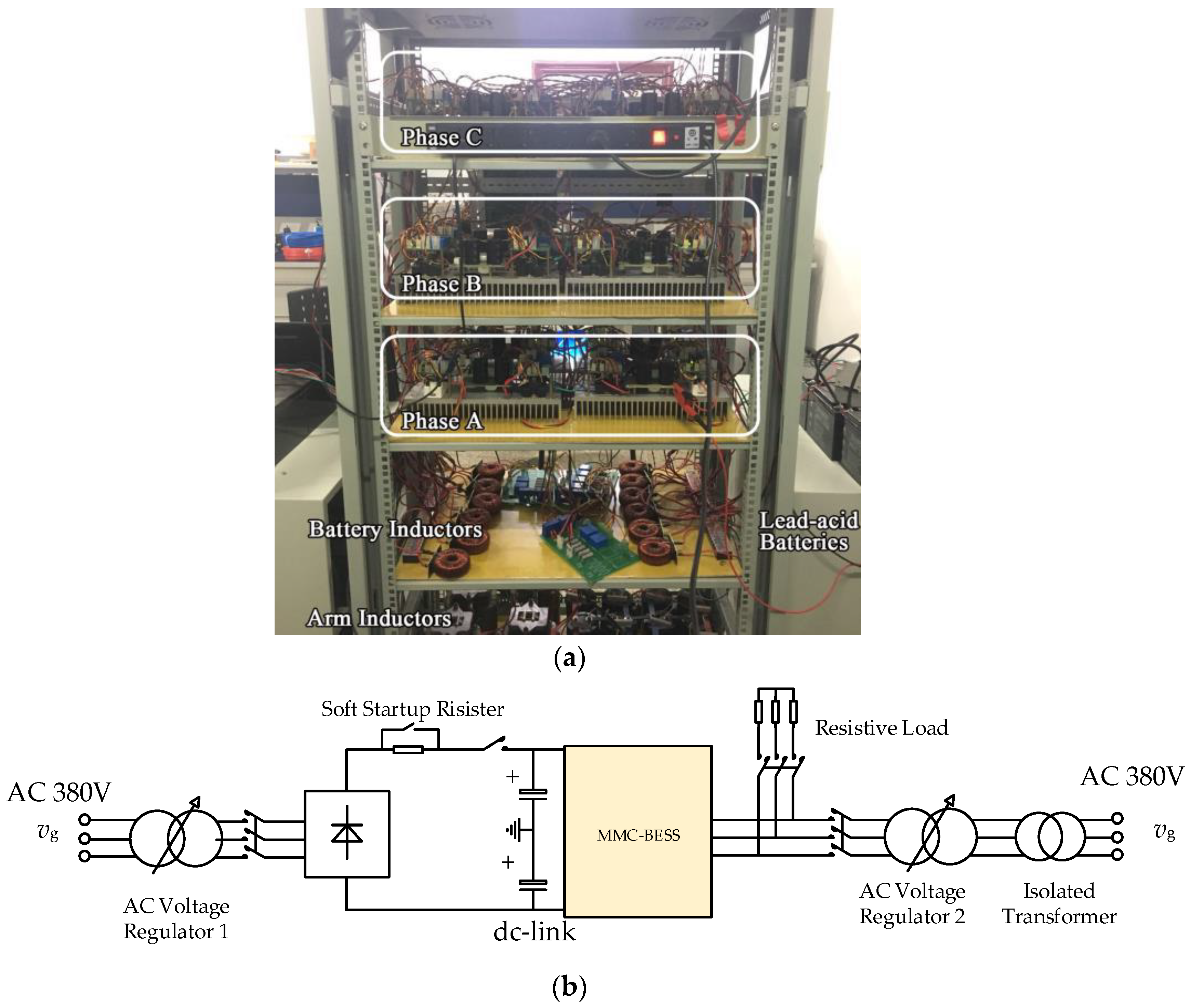
5.2. Experimental Results

To verify the proposed control strategy of the MMC-BESS, a downscaled prototype was built in the laboratory [24]. The configuration of the prototype is shown in Figure 16. The main parameters are listed in Table 2. The controller structure of the prototype was designed with a single digital-signal processor (DSP) as the main controller and three field-programmable gate arrays (FPGAs) as the auxiliary controllers in each phase. The battery module in individual SMs is composed of three 12 V/24 Ah lead-acid battery cells due to the consideration of cost reduction compared with other type of batteries [25]. Note that the switching frequency of battery side DC/DC converters is different from MMC side converters. Given that the power rate of individual batteries is usually lower than the MMC side, semiconductor devices and switching frequency can be selected separately at the battery side DC/DC converter [26]. With the development of wide bandgap devices, the conversion efficiency between batteries and MMC can be enhanced at high-power levels [27].

5.2.1. Verification of SOC Equalization

The experimental waveforms of rectifier mode operation in steady state are shown in Figure 17. During the operation, the references of Pac 800 W and an external 600 W DC load is connected to the DC-link throughout. In Figure 17a, the five-level modulation waveform of line voltage is presented with quite balanced capacitor voltages. Sinusoidal grid currents with low harmonic components are shown in Figure 17b. Circulating current of phase A is shown in Figure 17c with fundamental frequency component to equalize the SOC difference between upper and lower arms. Battery current with low harmonic components is also shown in Figure 17c to verify the effectiveness of the proposed capacitor voltage filter scheme. As the batteries operate in discharge mode, the SOC equalization process of the 12 battery modules are shown in Figure 17d. Due to the large capacity of the battery unit, the SOC equalization process is long, hence, the SOCs are sampled every ten minutes and presented by MATLAB.

5.2.2. Verification of Proposed Battery Side-Based Capacitor Voltage Control

The experimental waveforms of dynamic performance with and without the proposed control strategy at battery side are shown in Figure 18. The reference of AC power was 800 W throughout, and DC load was changed from 800 W to 500 W. Seen from Figure 18a, without the proposed control strategy at battery side, the battery current responded slowly, causing voltage fluctuation on capacitor voltage. Compared with Figure 18a, the battery current responded faster and capacitor voltage was stable during the power flow transfer process in Figure 18b. This comparison was in accordance with the simulation results in Figure 15.

5.2.3. Verification of Dynamics of Rectifier Mode Operation

The dynamic performance of rectifier mode operation is shown in Figure 19. Utilizing the proposed control strategy based on battery side capacitor voltage control, the DC-link voltage was controlled to 120 V throughout, AC power was regulated through the reference value directly according to the indications in Figure 19. The external 600 W DC load was connected to the DC-link during the operation, which is illustrated in the general view of the waveform. Seen from the experimental results, the AC power and DC-link voltage had no direct interactions due to the existence of additional power flow provided by the BESS, which is different from conventional MMCs. The dynamics of AC power and DC-link voltage were both able to satisfy the requirements of the system as a rectifier or a pure PCS.

6. Conclusions

In this paper, the control strategy of the MMC-BESS for rectifier mode operation with capacitor voltage controlled by a battery side DC/DC converter was proposed. The main contributions can be summarized as follows:
  • The reason why the rectifier mode control strategy in conventional MMCs invalidates in the MMC-BESS was analyzed in this paper. The ac power and dc power were decoupled by the battery side control, so it was impossible to control dc-link voltage through ac power. According to the analysis, the control strategy containing dc-link voltage control and SOC equalization was proposed in this paper to achieve the control objective based on battery side capacitor voltage control.
  • At battery side, since the capacitor voltage was stabilized by a battery side DC/DC converter, the control strategy of the DC/DC converter was key to the performance of the whole system. Therefore, an improved control strategy for an individual capacitor voltage control was proposed in this paper, enhancing the dynamic performance of capacitor voltage, meanwhile greatly reducing the occupied storage space of the MAF by using a common filter per phase arm. Seen from the simulation and experimental results, the proposed battery side control strategy can satisfy the requirements of rapidity and accuracy, facilitating the application of the MMC-BESS in practice.

Author Contributions

Z.W., H.L. and Y.M. conceived and discussed the implementation of the control strategy; Z.W. and Y.M. performed the experiments; H.L. supervised the progress of the project; Z.W. and Y.M. wrote the paper.

Funding

This research was funded by National Natural Science Foundation of China grant number 51741703.

Conflicts of Interest

The authors declare no conflict of interest.

References

  1. Carrasco, J.M.; Franquelo, L.G.; Bialasiewicz, J.; Galván, E.; Guisado, R.C.P.; Prats, M.Á.M.; León, J.I.; Moreno-Alfonso, N. Power-electronic Systems for the Grid Integration of Renewable Energy Sources: A Survey. IEEE Trans. Ind. Electron. 2006, 53, 1002–1016. [Google Scholar] [CrossRef]
  2. Rodríguez, J.; Bernet, S.; Wu, B.; Pontt, J.; Kouro, S. Multilevel Voltage-Source-Converter Topologies for Industrial Medium-Voltage Drives. IEEE Trans. Ind. Electron. 2007, 54, 2930–2945. [Google Scholar] [CrossRef]
  3. Lesnicar, A.; Marquardt, R. An Innovative Modular Multilevel Converter Topology Suitable for a Wide Power Range. In Proceedings of the 2003 IEEE Bologna Power Tech Conference Proceedings, Bologna, Italy, 23–26 June 2003; pp. 272–277. [Google Scholar]
  4. Debnath, S.; Qin, J.; Bahrani, B.; Saeedifard, M.; Barbosa, P. Operation, Control, and Applications of the Modular Multilevel Converter: A Review. IEEE Trans. Power Electron. 2015, 30, 37–53. [Google Scholar] [CrossRef]
  5. Perez, M.A.; Bernet, S.; Rodriguez, J.; Kouro, S.; Lizana, R. Circuit Topologies, Modeling, Control Schemes, and Applications of Modular Multilevel Converters. IEEE Trans. Power Electron. 2015, 30, 4–17. [Google Scholar] [CrossRef]
  6. Akagi, H. Classification, Terminology, and Application of the Modular Multilevel Cascade Converter (MMCC). IEEE Trans. Power Electron. 2011, 26, 3119–3130. [Google Scholar] [CrossRef]
  7. Vidal-Albalate, R.; Beltran, H.; Rolán, A.; Belenguer, E.; Peña, R.; Blasco-Gimenez, R. Analysis of the Performance of MMC under Fault Conditions in HVDC-Based Offshore Wind Farms. IEEE Trans. Power Del. 2016, 31, 839–847. [Google Scholar] [CrossRef]
  8. Mishra, S.; Palu, I.; Madichetty, S.; Suresh Kumar, L.V. Modelling of Wind Energy-Based Microgrid System Implementing MMC. Int. J. Energy Res. 2016, 40, 952–962. [Google Scholar] [CrossRef]
  9. Trintis, I.; Munk-Nielsen, S.; Teodorescu, R. A New Modular Multilevel Converter with Integrated Energy Storage. In Proceedings of the IECON 2011—37th Annual Conference of the IEEE Industrial Electronics Society, Melbourne, Australia, 7–10 November 2011; pp. 1075–1080. [Google Scholar]
  10. Quraan, M.; Tricoli, P.; D’Arco, S.; Piegari, L. Efficiency Assessment of Modular Multilevel Converters for Battery Electric Vehicles. IEEE Trans. Power Electron. 2017, 32, 2041–2051. [Google Scholar] [CrossRef]
  11. Vasiladiotis, M.; Rufer, A. Analysis and Control of Modular Multilevel Converters with Integrated Battery Energy Storage. IEEE Trans. Power Electron. 2015, 30, 163–175. [Google Scholar] [CrossRef]
  12. Baruschka, L.; Mertens, A. Comparison of Cascaded H-Bridge and Modular Multilevel Converters for BESS Application. In Proceedings of the 2011 IEEE Energy Conversion Congress and Exposition, Phoenix, AZ, USA, 17–22 September 2011; pp. 909–916. [Google Scholar]
  13. Hagiwara, M.; Maeda, R.; Akagi, H. Control and Analysis of the Modular Multilevel Cascade Converter Based on Double-Star Chopper-Cells (MMCC-DSCC). IEEE Trans. Power Electron. 2011, 26, 1649–1658. [Google Scholar] [CrossRef]
  14. Soong, T.; Lehn, P.W. Internal Power Flow of a Modular Multilevel Converter with Distributed Energy Resources. IEEE J. Emerg. Sel. Top. Power Electron. 2014, 2, 1127–1138. [Google Scholar] [CrossRef]
  15. Liang, H.; Guo, L.; Song, J.; Yang, Y.; Zhang, W.; Qi, H. State-of-Charge Balancing Control of a Modular Multilevel Converter with an Integrated Battery Energy Storage. Energies 2018, 11, 873. [Google Scholar] [CrossRef]
  16. Quraan, M.; Yeo, T.; Tricoli, P. Design and Control of Modular Multilevel Converters for Battery Electric Vehicles. IEEE Trans. Power Electron. 2016, 31, 507–517. [Google Scholar] [CrossRef]
  17. Chen, Q.; Li, R.; Cai, X. Analysis and Fault Control of Hybrid Modular Multilevel Converter with Integrated Battery Energy Storage System. IEEE J. Emerg. Sel. Top. Power Electron. 2017, 5, 64–78. [Google Scholar] [CrossRef]
  18. Li, Y.; Shi, X.; Liu, B.; Lei, W.; Wang, F.; Tolbert, L.M. Development, Demonstration, and Control of a Testbed for Multiterminal HVDC System. IEEE Trans. Power Electron. 2017, 32, 6069–6078. [Google Scholar] [CrossRef]
  19. Antonopoulos, A.; Angquist, L.; Nee, H.-P. On Dynamics and Voltage Control of the Modular Multilevel Converter. In Proceedings of the 2009 13th European Conference on Power Electronics and Applications, Barcelona, Spain, 8–10 November 2009; pp. 1–10. [Google Scholar]
  20. Ilves, K.; Harnefors, L.; Norrga, S.; Nee, H.-P. Analysis and Operation of Modular Multilevel Converters with Phase-Shifted Carrier PWM. IEEE Trans. Power Electron. 2015, 30, 268–283. [Google Scholar] [CrossRef]
  21. Zhang, J.; Lai, J.S.; Yu, W. Bidirectional DC-DC Converter Modeling and Unified Controller with Digital Implementation. In Proceedings of the 2008 23rd Annual IEEE Applied Power Electronics Conference and Exposition, Austin, TX, USA, 24–28 February 2008; pp. 1747–1753. [Google Scholar]
  22. Zhu, G.; Ruan, X.; Zhang, L.; Wang, X. On the Reduction of Second Harmonic Current and Improvement of Dynamic Response for Two-Stage Single-Phase Inverter. IEEE Trans. Power Electron. 2015, 30, 1028–1041. [Google Scholar] [CrossRef]
  23. Golestan, S.; Ramezani, M.; Guerrero, J.M.; Freijedo, F.D.; Monfared, M. Moving Average Filter Based Phase-Locked Loops: Performance Analysis and Design Guidelines. IEEE Trans. Power Electron. 2014, 29, 2750–2763. [Google Scholar] [CrossRef]
  24. Wang, Z.; Lin, H.; Ma, Y.; Wang, T. A Prototype of Modular Multilevel Converter with Integrated Battery Energy Storage. In Proceedings of the 2017 Applied Power Electronics Conference and Exposition (APEC), Tampa, FL, USA, 26–30 March 2017; pp. 434–439. [Google Scholar]
  25. Keshan, H.; Thornburg, J.; Ustun, T.S. Comparison of Lead-Acid and Lithium Ion Batteries for Stationary Storage in Off-Grid Energy Systems. In Proceedings of the 4th IET Clean Energy and Technology Conference (CEAT 2016), Kuala Lumpur, Malaysia, 14–15 November 2016; pp. 1–7. [Google Scholar]
  26. Soong, T.; Lehn, P.W. Evaluation of Emerging Modular Multilevel Converters for BESS Applications. IEEE Trans. Power Del. 2014, 29, 2086–2094. [Google Scholar] [CrossRef]
  27. Hudgins, J.L.; Simin, G.S.; Santi, E.; Khan, M.A. An Assessment of Wide Bandgap Semiconductors for Power Devices. IEEE Trans. Power Electron. 2003, 18, 907–914. [Google Scholar] [CrossRef]
Figure 1. Applications of modular multilevel converter (MMC) topology with large-scaled renewable energy sources. (a) Offshore wind farm generation system based on two-terminal MMCs. (b) DC microgrid using MMC as interlinking converter.
Energies 12 02151 g001
Figure 2. Topology of the three-phase MMC- battery energy storage system (BESS).
Energies 12 02151 g002
Figure 3. Power flows of the MMC-BESS.
Energies 12 02151 g003
Figure 4. Three-level State-of-charge (SOC) equalization control. (a) SOC equalization among three phases. (b) SOC equalization between upper and lower arms. (c) SOC equalization among submodules (SMs) within phase arm.
Energies 12 02151 g004
Figure 5. DC side equivalent circuit of the MMC-BESS.
Energies 12 02151 g005
Figure 6. DC-link voltage control diagram.
Energies 12 02151 g006
Figure 7. Circulating current control diagram.
Energies 12 02151 g007
Figure 8. Overall control strategy of the MMC-BESS based on battery side capacitor voltage control.
Energies 12 02151 g008
Figure 9. Local circuit of the bidirectional DC/DC converter with control diagram.
Energies 12 02151 g009
Figure 10. Capacitor voltages within one phase arm under unbalanced battery powers. (a) Unbalanced battery currents within phase arm. (b) Capacitor voltages within phase arm.
Energies 12 02151 g010
Figure 11. Improved control strategy based on moving average filter (MAF) for individual bidirectional DC/DC converter.
Energies 12 02151 g011
Figure 12. Simplified control block diagram of the individual DC/DC converter.
Energies 12 02151 g012
Figure 13. Simulation waveforms of rectifier mode operation of MMC-BESS. (a) Grid currents. (b) DC-link voltage. (c) Capacitor voltages of upper and lower arm of phase A. (d) Circulating currents. (e) Battery currents of SMs within upper arm of phase A.
Energies 12 02151 g013
Figure 14. Three-level SOC equalization results. (a) SOC equalization of all 24 SMs. (b) SOC equalization among three phases. (c) SOC equalization between upper and lower arms of phase A. (d) SOC equalization among SMs within upper arm of phase A.
Energies 12 02151 g014
Figure 15. Verification of proposed battery side capacitor voltage control strategy. (a) Without estimated feedforward component. (b) Utilizing MAF each SM with estimated feedforward component. (c) Utilizing proposed common MAF each phase arm with estimated feedforward component.
Energies 12 02151 g015
Figure 16. Configuration of the three-phase MMC-BESS prototype. (a) Picture. (b) Circuit.
Energies 12 02151 g016
Figure 17. Experimental waveforms of steady-state operation of the MMC-BESS. (a) Modulated voltage waveform. (b) Grid currents and capacitor voltage. (c) Circulating current and battery current. (d) SOC equalization process.
Energies 12 02151 g017
Figure 18. Experimental waveforms of dynamic performance of the MMC-BESS. (a) Without the proposed control strategy. (b) With the proposed control strategy.
Energies 12 02151 g018
Figure 19. Experimental waveforms’ dynamic performances of rectifier mode operation with proposed control strategy.
Energies 12 02151 g019
Table 1. Main parameters of the MMC-BESS simulation model.
SymbolQuantityValue
VgGrid voltage (line-to-ground, Root Mean Square (RMS) value)1.13kV (M = 0.8)
VdcDC-link voltage4 kV
SratedRated apparent output power1 MVA
fAC line frequency50 Hz
LsArm inductance5 mH
NSubmodule (SM) number per phase arm4
CSM capacitance3000 μF
VbRated battery voltage600 V
LbBattery side DC/DC converter inductance5 mH
QbRated battery capacity0.3 Ah
fsmCarrier frequency at MMC side modulation2 kHz
fsbBattery side converter switching frequency10 kHz
Table 2. Main parameters of the prototype.
SymbolQuantityValue
VgGrid voltage (line-to-ground, RMS)48V (M = 0.8)
VdcDC-link voltage120 V
LsArm inductance5 mH
NSM number per arm2
CSM capacitance3000 μF
VbRated battery voltage36 V
LbBattery side DC/DC converter inductance5 mH
QbRated battery capacity24 Ah
fsmCarrier frequency at MMC side modulation2 kHz
fsbBattery side converter switching frequency10 kHz

