Article

Providing Ancillary Services with Wind Turbine Generators Based on DFIG with a Two-Branch Static Converter

by
Ernande Eugenio C. Morais
1,2,*,†,
Francisco Kleber de A. Lima
1,†,
Jean M. L. Fonseca
1,†,
Carlos G. C. Branco
1 and
Lívia de A. Machado
1,†
1
Department of Electrical Engineering, Federal University of Ceara, Fortaleza CE 60020-181, Brazil
2
Federal Institute of Education, Science and Technology of Ceara, Jaguaribe CE 63475-000, Brazil
*
Author to whom correspondence should be addressed.
These authors contributed equally to this work.
Energies 2019, 12(13), 2490; https://doi.org/10.3390/en12132490
Submission received: 30 May 2019 / Revised: 25 June 2019 / Accepted: 26 June 2019 / Published: 28 June 2019

Abstract

:
This work aims to analyze and validate through mathematical modeling and experimental results, in a three-phase three-wire electrical system, the technical viability of a static power converter with a two-level topology with only two controlled branches (2L2B), operating as a grid-side converter (GSC) in a wind turbine generator based on a doubly fed induction generator (DFIG). With this reduced-switches topology, the GSC is able to regulate the DC-link voltage level from the generator back-to-back converter and provide ancillary services of harmonic filtering and reactive power compensation from linear/nonlinear loads connected to the point of common coupling. An 8-kVA experimental prototype was implemented in the laboratory to validate the proposal. The prototype control system was realized using the dSPACE DS1103 PPC Controller Board platform programmed via MATLAB/Simulink. The effectiveness of the proposed system is verified by comparing the results obtained with the 2L2B topology to the ones with the usual two-level three-branch topology.

1. Introduction

In 2017, about 82% of the installed capacity of the world’s wind power generation was due to the doubly fed induction generator (DFIG), or Type III turbines; Figure 1 [1,2]. This record has highlighted the importance of the role which static power converters play in distributed energy resources (DER) [3]. Within this context, several converter topologies were considered to be employed in a DFIG system. However, 90% of the converters employed in low-voltage Type III wind turbine generators (WTG), with rated power between 1.5 MW to 3.0 MW, are the basic two-level topology (see Figure 2b) in the back-to-back configuration. In this configuration, the rotor-side converter (RSC) controls the DFIG stator power, while the grid-side converter (GSC) regulates the voltage at the DC link, and also performs the reactive power compensation [4,5]. Although they are widely present in today’s wind power generation market, Type III WTG still have a vast range of problems and solutions that attract continuous efforts from researchers aiming to improve their performance as DERs and reduce operation and maintenance costs [5,6,7,8,9,10,11,12,13,14,15,16].
Due to location in remote areas, the WTGs often operate with voltage unbalanced due to weak power grid. These unbalanced voltages can cause overheating of the DFIG stator windings, oscillations at twice the frequency of the grid in the electric power supplied and in the electromagnetic torque, mechanical stress and fatigue on important constructive components, overvoltages on the DC bus and switches of the converters of the generator and, consequently, the eventual shutdown of the WTG from the electrical system [6,17]. Many problems associated with Type III WTGs are related to the quality of energy delivered. These problems are associated with electrical disturbances from the electrical grid or the WTG’s own operation. In [7] are investigated the effects that the currents harmonics in the DFIG stator windings can produce in the rotor. Harmonics, interharmonics, and non-characteristic harmonics in the rotor current, overheating in the rotor windings, torque pulsation and mechanical stress in the drivetrain system of the turbine, are some of these effects. In [18] are analyzed the low frequency harmonics due to the operation of the RSC in the Type III WTGs and as these harmonics, associated with the wind oscillations, significantly change the harmonic spectrum of the current in the stator even if the converter operates with high-frequency switching. Unbalances and harmonic voltage distortions at the stator terminals contribute to the quality degradation of the power delivered by the generator and may impair the performance of the converters in back-to-back configuration in the Type III WTG [19,20]. Distorted voltages at the DFIG stator terminals, together with the wind speed variation and the DFIG slip, influence the emergence of current harmonics and interharmonics in the DFIG [21]. In [12] it is observed that high-power single-phase loads, such as electric trains, contribute to the voltages unbalanced in the areas where wind farms are located. The current harmonic components of the DFIG can also be derived from nonlinear loads [12]. In general, the current harmonics in the rotor and stator windings of the DFIG are strongly influenced by the GSC and RSC, respectively [9]. However, the DFIG slip exerts a modulation effect on the current harmonics of the stator [9]. Voltages unbalanced interfere in the operation of the DFIG’s converters generating low-order current harmonics. The low-order current harmonics can also be caused by the low-order harmonics present in the grid voltage and by nonlinear loads requiring power from the DFIG [9]. It is also observed in [9,15] that high order and low-order harmonics and interharmonics are equally significant during the WTG operation. Some problems, such as the presence of collector rings and brushes, still make it impossible to apply DFIGs in offshore wind farms [5].
To improve the energy quality of the Type III WTGs, some solutions are adopted with respect to the control strategies of the GSC and RSC converters. Through of resonant compensators and repetitive control, in [10,22,23] are applied control strategies to RSC that aim to compensate current harmonics in the terminals of the DFIG stator, when fed by distorted voltages. The compensations of the fifth and seventh order current harmonics in the stator can also be made by the RSC using only resonant compensators tuned to the sixth order harmonics [12,13,19,24,25]. In [26,27], the control strategy applied to the RSC, using resonant compensators, aims to compensate the voltage harmonics in the stator. In this case, the voltage distortions are due to the presence of nonlinear loads that demand distorted currents. These currents deform the voltages along the grid impedances. In [11] it is proposed a mitigation strategy of current harmonics by the GSC. According to [11], the compensation of harmonics by the RSC can generate losses in the rotor and stator windings and noise in the DFIG, in addition, a possible shutdown of the generator could prevent the harmonic filtering operation by RSC. Thus, the use of the GSC as an active filter can be maintained even with the WTG out of operation, besides not directly harming the operation of the DFIG. There are also works that proposed the coordinated operation of the RSC with the GSC to increase the fault ride-through operational capability guaranteeing a constant active power supply. Another possibility of coordinated operation between the RSC and the GSC is the regulation of the positive and negative-sequence components of the currents and the compensation of their harmonics [14,20].
The high level of robustness and versatility of Type III WTGs is due to advances in both the control strategies and circuits, as well as in the power circuits of the static power converters applied [16]. In this way, topologies of multilevel converters have been developed to guarantee the reliable drive of generators with increasing nominal powers and voltages. However, the use of more solid-state power switches increases the costs of investment, operation, and maintenance. Thus, the idea of discarding the use of switches in a branch of three-phase converters becomes interesting both for multilevel topology converters and for two-level topology converters (2L), which are the most used in Type III WTG [2,4,5,16]. Directing the focus of this work to the 2L topology converters, were verified that many studies detailed this topology operating with two branches (2L2B); Figure 2a. For instance, in [28] it was proposed the stand-alone use of the 2L2B connected to a linear load, operating with an adaptive pulse width modulation (PWM) technique. A review of the topologies of AC–DC converters, such as 2L2B, used in industry for the improvement of energy quality is presented in [29]. In the studies presented in [30,31,32,33,34], the 2L2B topology is analyzed as an active shunt filter, being employed various types of control strategies in synchronous reference frame or stationary one, with different modulation techniques. A variation of the topology 2L2B shown in Figure 2a is discussed in [35,36,37] as a power hybrid filter. In [38,39] two three-phase multilevel topologies, Neutral Point Converter (NPC) and Capacitor-Clamped Converter, are proposed to operate as active filters with only two branches with switches. In all these works, the operational efficiency and commercial employability of the 2L2B topology was attested.
Based on the market trend of WTG operating with increasingly higher rated power and voltage levels, and the use of multilevel converters [2,4,5,16], this paper aims at analyzing the operational feasibility of a Type III turbine, with a three-phase power converter with only two branches being controlled, in a three-phase three-wire electrical system. To do so, it is proposed the use of a two-level and two-branch (2L2B) topology as GSC, Figure 2a. To verify its versatility within a back-to-back configuration, in comparison with the usual two-level three-branch (2L3B) shown in Figure 2b, a control strategy applied to the 2L2B is implemented allowing DC-link regulation and, at the same time, performing ancillary services of harmonic filtering and reactive power compensation. With respect to the RSC, the topology employed is still the usual 2L3B, and its control strategy aims at independently control the stator’s active and reactive power. As such, this work presents a solution that reduces cost for operation and maintenance while enhancing the system’s power quality where the Type III WTG is connected.
Some references have already presented studies on the use of the 2L2B topology for the drive and control of the power direction of electric machines, operating as a motor or generator. In [40,41], for example, stand-alone systems are presented, in which the 2L2B topology is used to drive permanent magnet synchronous motor. In other works, it is proposed the use of a converter in back-to-back configuration for the drive of an electric machine, where the rectifier and the inverter are of 2L2B topology [42,43]. Especially in [43], the electric machine driven by the back-to-back converter is a DFIG, configuring a Type III WTG. In fact, such study presented the RSC control, with 2L2B topology, with three selectable targets (constant stator power, constant electromagnetic torque and balanced stator currents) that cannot act simultaneously, while the GSC control, also with 2L2B topology, is responsible for DC-link voltage regulation maintaining a unity power factor at its terminals. The operation of the system proposed in [43] is analyzed under unbalanced grid voltage condition and the system performance is evaluated through simulation results. However, the system proposed in [43] reduces the insulation capacity of the back-to-back converter against the propagation of electrical disturbances between the DFIG rotor circuit and the grid. In [44], it is proposed the use the 2L2B topology, as GSC, connected to a DC/DC full-bridge converter by the DC link, to ensure greater stability and electrical insulation between the AC and DC sides. However, the structure presented in [44] would make the back-to-back converter more expensive and with more complex control due to the use of more magnetic semiconductors and capacitors. In [45] the 2L2B topology is employed as GSC, while the conventional 2L3B topology is used as RSC, such as proposed in this paper. In [45], the GSC control strategy, implemented in synchronous reference frame using space vector modulation, aims to regulate DC-link voltage by maintaining a unity power factor at its terminals. In this proposed work, unlike [43,45], the control of the RSC aims to control the active and reactive powers of the stator of the DFIG keeping only the rotor currents balanced, to allow long periods of operation of the WTG system maintaining a balanced heating in the rotor windings. The control of current, in the RSC control, is made through resonant compensators. The conventional 2L3B topology is employed to the RSC in order to guarantee a certain insulation to the electrical disturbances between the rotor circuit and the grid, unlike [43], while its implementation becomes less expensive and complex in relation to what is proposed in [44]. The GSC control performs two functions within the Type III WTG system, as well as regulating of the DC link by maintaining a unity power factor at its terminals. The GSC compensates for the current harmonics that can be generated by nonlinear loads, connected at the common connection point, Figure 1, and by the DFIG at low wind speeds. Due to the rapid dynamics of incoming and outgoing of loads from the grid, the GSC can assist the RSC in the compensation of the excess reactive energy that tends to flow between the grid and the system composed by the WTG and loads. This paper does a detailed mathematical analysis of the ability of the 2L2B topology to synthesize positive and negative-sequence current components at the fundamental and harmonic frequencies, of the DC-link regulation strategy and of the modulation technique to be applied. The control strategy used for the GSC uses fewer PI compensators compared to [45] and can be applied to both the 2L2B topology and the 2L3B topology. The proposal of this paper and the comparative analysis between 2L2B and 2L3B topologies as GSC are verified experimentally.
This work is organized as follows: Section 2 defines the stationary and synchronous reference frames, in which the control variables of the GSC and RSC are manipulated, and the synchronization structure used is shown. In Section 3, the control strategy for the RSC is presented. The analysis of the 2L2B topology employed as a GSC and its control strategy are shown in Section 4 and Section 5, respectively. Lastly, experimental results and its discussions, as well as conclusions are presented in Section 6 and Section 7.

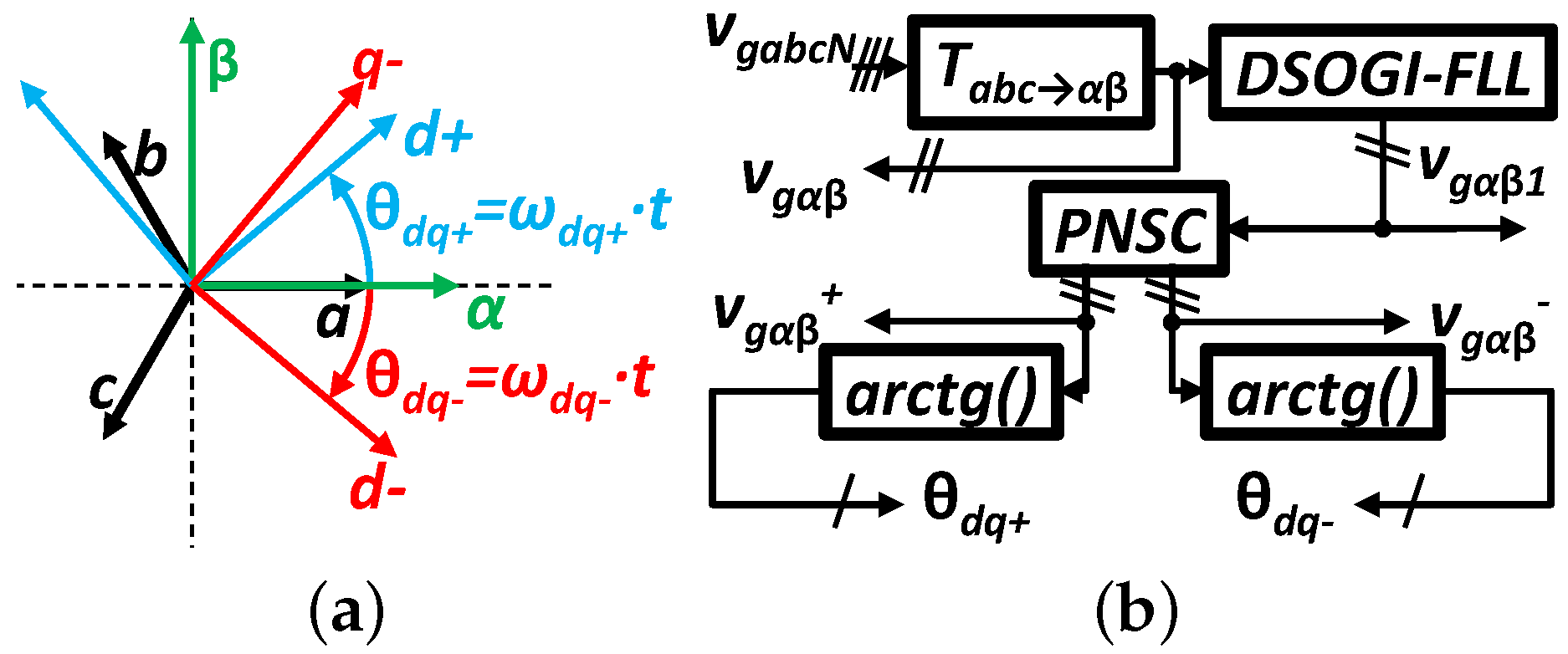
2. Reference Frame and Synchronization System

The control scheme for the back-to-back converter implemented in dSPACE is divided in two parts: the GSC control and the RSC control. The first one uses variables in the stationary frame, α β , whereas the latter uses variables in the synchronous reference frame (SRF), d q . The reason for this reference frame configurations is due to the different control strategies employed in each converter, as well as the reduction of computational effort for the dSPACE. Figure 3a illustrates the stationary frames, a b c and α β , and the SRF, d q [46].
The transformation matrices used to obtain the positive and negative-sequence components ( x ˙ + and x ˙ ) and to change between the different frames, a b c , α β and d q are shown in (1). The three-phase three-wire scenario implies a non-observance of the homopolar components in (1).
x ˙ + x ˙ = 1 3 · 1 α α 2 1 α 2 α · x ˙ a x ˙ b x ˙ c , α = e j 2 π / 3 , T a b c α β = 1 1 / 2 1 / 2 0 3 / 2 3 / 2 , T α β d q + = cos θ d q + sin θ d q + sin θ d q + cos θ d q + , T α β d q = cos θ d q sin θ d q sin θ d q cos θ d q .
To synchronize the back-to-back converter to the grid, the Dual Second Order Generalized Integrator–Frequency-Locked Loop (DSOGI–FLL), with FLL gain normalization and positive and negative-sequence calculation (PNSC) [46], is used (see Figure 3b). Using this structure, which is well-known for its robustness to imbalance and harmonic distortion in the input signal, the positive- and negative-sequence components can be quickly obtained.

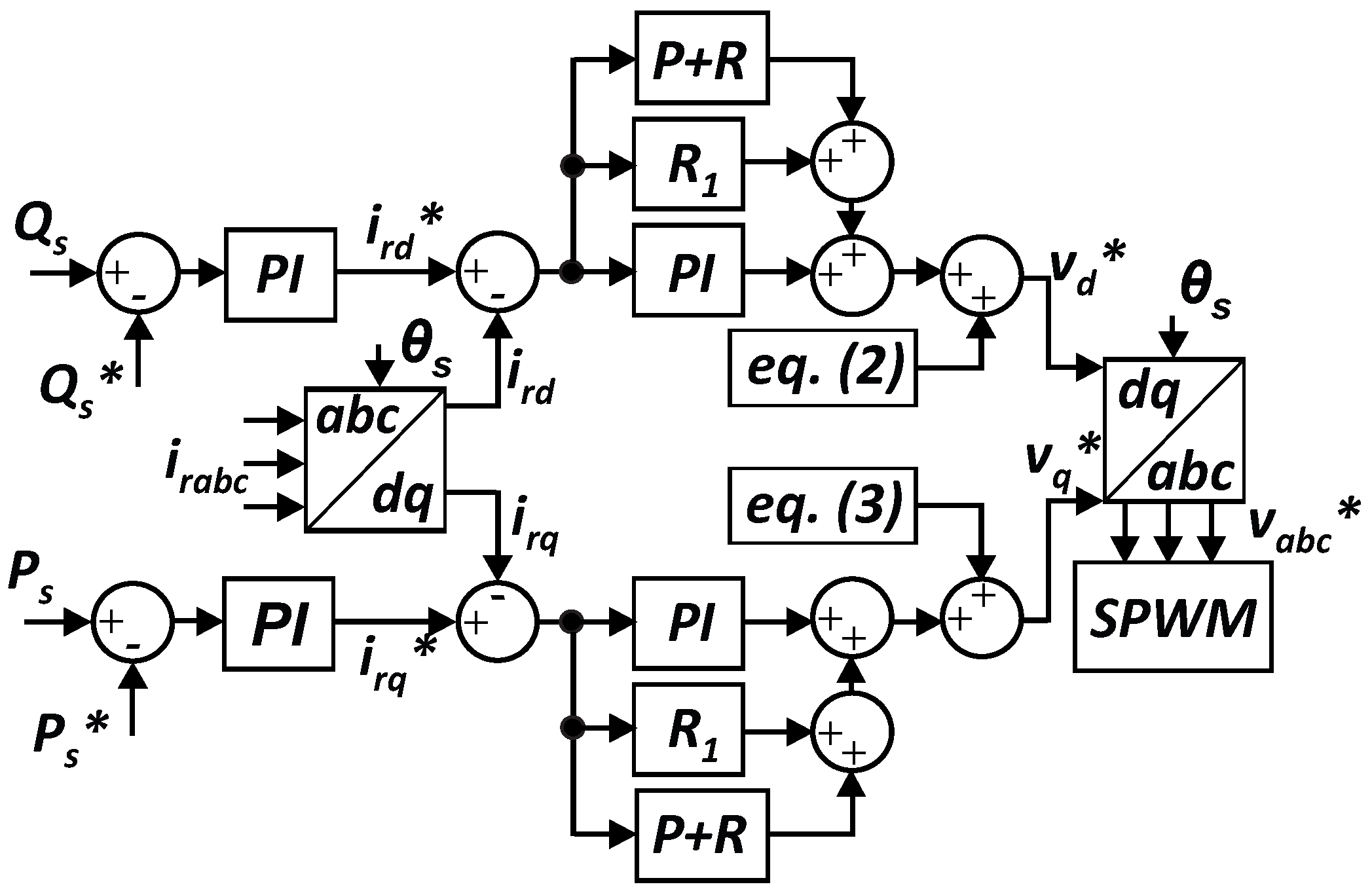
3. Rotor-Side Converter Control Strategy

The objective of the RSC control strategy is to independently control the average value of the DFIG’ stator active and reactive power, keeping the losses balanced in the windings of its rotor. For this reason, a resonant compensator, R 1 , and a proportional-resonant, P + R , are used to compensate the negative-sequence components of the rotor currents ( i r d = i r q = 0 ), without the need to separate the positive and negative-sequence components from the control reference signals [12,13,14]. The field-oriented control strategy [47], as shown in Figure 4, is implemented with the addition of the feedforward terms ( μ v r d ) and ( μ v r q ) that allow the decoupled control of d- and q-axis currents. These terms are defined in (2) and (3) [47,48].
μ v r d = ω r + · L r s · i r q · σ v g d N · 1 σ ω s · L m ,
μ v r q = ω r + · L r s · i r d · σ + v g q N · 1 σ ω s · L m ,
where ω r + is the positive-sequence rotor electric frequency and ω s is the stator electric frequency. L r s is the rotor inductance referred to the stator side and L m is the DFIG’s magnetizing inductance. Variables v g d N and v g q N are the grid voltages in the SRF. Lastly, i r d and i r q are the reference positive-sequence rotor currents, being calculated after setting values for the stator active and reactive power ( P s and Q s ), as shown in (4) and (5). It is important to highlight that the equations are obtained by considering the negative-sequence rotor currents equal to zero, i.e., i r d = i r q = 0 [12,13,14]. In (4) and (5), L s is stator inductance.
i r d = v g q N + 2 v g d N 2 v g q N 2 Q s · ω s · L s v g q N + · ω s · L m ,
i r q = P s · L s v g q N + · L m .

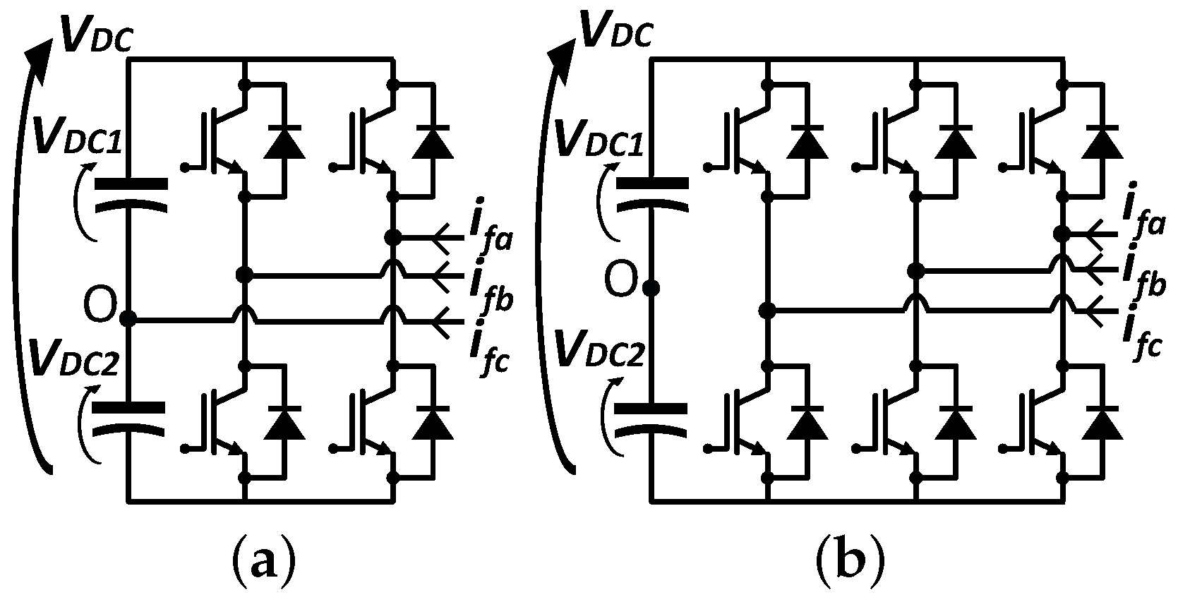
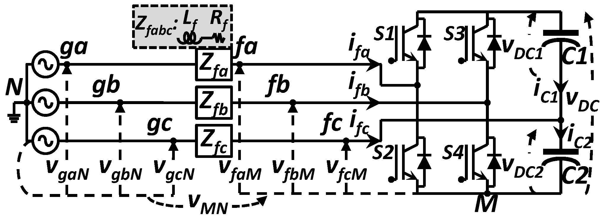
4. Grid-Side Converter with 2L2B Topology

The operation of the GSC with 2L2B topology can be analyzed similarly to a grid-connected converter operating as an active filter, due to the isolated DC link in a back-to-back configuration [30,31,32,36,38,39]. From Figure 5, (6) is derived using Kirchhoff’s Voltage Law (KVL) in each phase, furthermore, the analysis considers grid voltages to be balanced and distortion-free.
v g a N + R f · i f a + L f · d i f a d t + v f a N = 0 , v g b N + R f · i f b + L f · d i f b d t + v f b N = 0 , v g c N + R f · i f c + L f · d i f c d t + v f c N = 0 .
The voltages v f a N , v f b N and v f c N , referred to the grid neutral point N, are described in (7) considering the voltage between N and the converter negative terminal M, v M N :
v f a N = v f a M + v f M N , v f b N = v f b M + v f M N , v f c N = v f c M + v f M N .
Applying Kirchhoff’s Current Law (KCL) at node N, it is possible to show that the voltage drop v Z f a , v Z f b and v Z f c , will be balanced as long as the resultant impedance up to the GSC terminals are balanced, i.e., Z f a b c = Z f . If that is the case, v f a N , v f b N and v f c N , are balanced as well.
Z f · i f a + Z f · i f b + Z f · i f c = 0 v Z f a + v Z f b + v Z f c = 0 , v Z f a + v Z f b + v Z f c = 0 v f a N + v f b N + v f c N = 0 .
By summing up the expressions in (7) and substituting the resulting expression in (8), v M N can be written as:
v M N = v f a M + v f b M + v f c M / 3 .
From (7) and (9), the DC voltage levels in the GSC terminals are defined as shown in Table 1.
Reference [36] shows that it is possible to elaborate the circuit analysis of the 2L2B topology by breaking down the variables into three parts: DC, AC at fundamental frequency, and AC at high-frequency harmonics. In the DC analysis, the grid operates as a short-circuit, since it does not have DC components, and Z f is limited to R f . Thus, the DC voltage drop at this impedance can be calculated as the following.
( v Z f a ) D C = ( v Z f b ) D C = V D C / 2 , ( v Z f c ) D C = V D C .
From (10), it can be noticed that the voltage across Z f will be small, as long as R f value is low.
Disregarding voltage oscillations on capacitors C 1 and C 2 , a short-circuit between terminals f c and M is considered for the AC analysis. Under fundamental frequency, the grid voltages can be described as phasors:
v ˙ g a N 1 = V 1 , v ˙ g b N 1 = α 2 · V 1 , v ˙ g c N 1 = α · V 1 ,
where V 1 is the grid phase-voltage RMS value at fundamental frequency and α is defined in (1).
Using phasors to analyze (6), the voltage drop at the overall input impedance for each phase is obtained in (12).
v ˙ Z f a 1 = v ˙ f b M 1 2 · v ˙ f a M 1 + 3 · V 1 / 3 , v ˙ Z f b 1 = v ˙ f a M 1 2 · v ˙ f b M 1 + 3 · α 2 · V 1 / 3 , v ˙ Z f c 1 = v ˙ f a M 1 + v ˙ f b M 1 + 3 · α · V 1 / 3 .
In three-phase three-wire system, loads (depending if they are linear/nonlinear or balanced/unbalanced) can demand reactive power with oscillating and average components. The association between v ˙ f a M 1 and v ˙ f b M 1 when the GSC injects positive and negative currents at fundamental frequency, can be found in (13) and (14). In the scenario where negative-sequence currents are synthesized, the positive-sequence voltage across Z f , from (12) is zero. The opposite occurs when positive-sequence currents are synthesized.
v ˙ f a M 1 = α · v ˙ f b M 1 + 3 · V 1 v ˙ Z f a b c 1 + = 0 ,
v ˙ f a M 1 = α 2 · v ˙ f b M 1 v ˙ Z f a b c 1 = 0 .
From (13) and (14), it can be noticed that v ˙ f a M 1 and v ˙ f b M 1 are phase-shifted by 60 . In (13), v ˙ f a M 1 is lagging with respect to v ˙ f b M 1 , whereas in (14) the signal is leading. Furthermore, synthesizing negative-sequence currents at fundamental frequency, demands higher voltage values at the terminals of the GSC, as shown in (13). Equations (15) and (16) are obtained by substituting (13) and (14) into (12).
v ˙ f a M 1 = α 2 α 3 · v ˙ Z f a 1 + α 3 α · V 1 , v ˙ f b M 1 = α α 3 · v ˙ Z f b 1 + α 2 α · V 1 .
v ˙ f a M 1 = α α 3 · v ˙ Z f a 1 + + α 3 α · V 1 , v ˙ f b M 1 = α 2 α 3 · v ˙ Z f b 1 + + α 2 α · V 1 .
Then, it can be observed that v ˙ f a M 1 and v ˙ f b M 1 variables are approximately equal to the grid line voltage.
Under the AC analysis for harmonic components, the grid is considered short-circuited, as it is assumed that the grid voltages are distortion-free. Thus, (17) is obtained considering (12) for high-frequency harmonic components.
v ˙ Z f a h = 2 · v ˙ f a M h v ˙ f b M h / 3 , v ˙ Z f b h = v ˙ f a M h + 2 · v ˙ f b M h / 3 , v ˙ Z f c h = v ˙ f a M h v ˙ f b M h / 3 .
Similar to the analysis previously shown for the fundamental frequency components, the relation between voltages v ˙ f a M h and v ˙ f b M h , in (17) that are employed in order to synthesize negative- and positive-sequence current components at higher frequencies, are shown in (18) and (19).
v ˙ f a M h = α · v ˙ f b M h v ˙ Z f a b c h + = 0 ,
v ˙ f a M h = α 2 · v ˙ f b M h v ˙ Z f a b c h = 0 .
To synthesize high-frequency currents, v ˙ f a M h and v ˙ f b M h are also phase-shifted by 60 for either negative- or positive-sequence components. Again, v ˙ f a M h is lagging with respect to v ˙ f b M h in (18) and leading in (19). Substituting (18) and (19) in (17), the following equations are obtained.
v ˙ f a M h = α 3 α 2 · v ˙ Z f a h , v ˙ f b M h = α 3 α · v ˙ Z f b h .
and
v ˙ f a M h = α 3 α · v ˙ Z f a h + , v ˙ f b M h = α 3 α 2 · v ˙ Z f b h + .
Equations (20) and (21), show that v ˙ f a M h and v ˙ f b M h are 3 times greater than v ˙ Z f a h and v ˙ Z f b h .
Equations (13), (14), (18) and (19), obtained in the AC analysis, demonstrate that the 2L2B topology as GSC can provide negative- and positive-sequence currents; however, the power injected is limited by the converter as well as the filters connected to its terminals, Z f , as shown in (15), (16), (20) and (21).

5. Grid-Side Converter Control Strategy

The GSC control strategy has two main goals: power conditioning and DC-link regulation. Power conditioning characterizes the ancillary functions provided by the GSC to the grid and is divided into harmonic filtering and reactive power compensation. As for the DC-link regulation, the voltage level at the DC bus is regulated to balance the voltage levels at capacitors C 1 and C 2 .

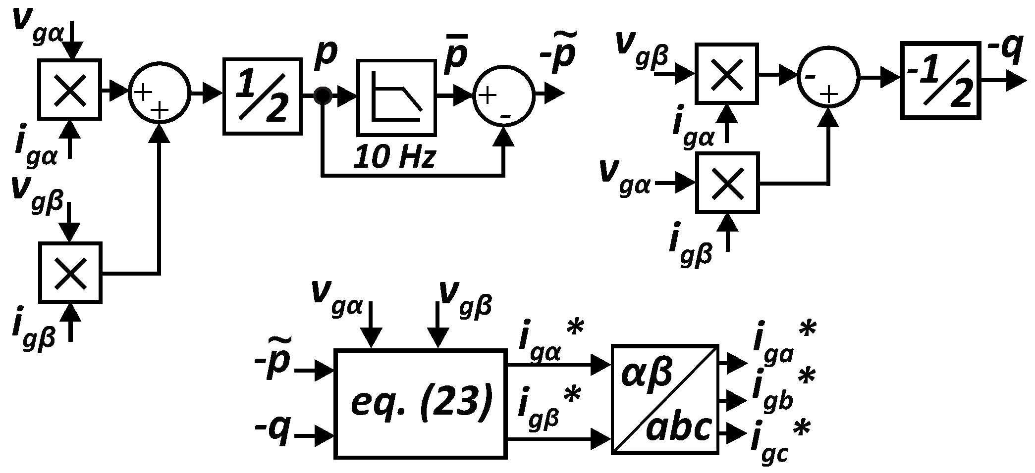
5.1. Harmonic Filtering and Reactive Power Compensation

The instantaneous reactive and active power theory, employed in the α β frame, is applied to compensate reactive power and filter harmonic distortion [49]. Equation (22), refers to the overall power flowing from/to the grid that consists of the Type III WTG and the nonlinear load group. From (22) and using Figure 1 as reference, it is possible to calculate the compensating current components to be synthesized by the GSC, as depicted in (23).
p g q g = p ¯ g + p ˜ g q ¯ g + q ˜ g = v g α N v g β N v g β N v g α N · i g α i g β ,
i g α i g β = 1 v g α N 2 + v g β N 2 · v g α N v g β N v g β N v g α N · p ˜ g q g .
Figure 6 illustrates the block diagram of the GSC control strategy. Furthermore, the reference currents are also multiplied by a gain, k a b c , which increases proportionally to the overall compensation (see Figure 7).

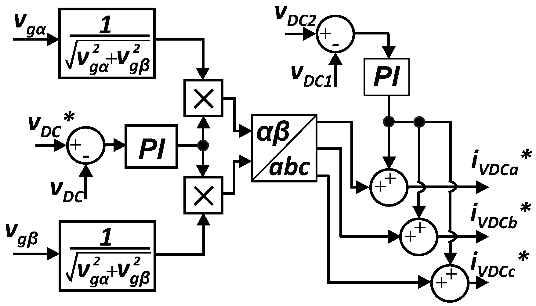
5.2. DC-Link Regulation

For the DC-link regulation we can consider that the GSC is operating with only this objective. That being the case, the GSC can demand active power, due to the converter losses, and reactive power, due to negative-sequence harmonics arising from its switching operation and passive elements being present in the structure. Thus, the regulation aims to maintain a unity power factor, i.e., no reactive power. Considering the grid voltages to be balanced, and the α and d axis to be aligned, by the relations T a b c α β and T α β d q + expressed in (1), v g q N will be zero. From (22), the converter reactive power is expressed in (24) as function of its currents and the grid voltage, both in the d q frame.
q G S C = v g d N · i f q v g q N · i f d = v g d N · i f q .
It can be concluded from (24) that since v g d N is constant, i f q has oscillating and average components. Considering C 1 = C 2 = C , and that the value of C is large enough to assume voltage oscillations at the DC link near zero, i f q tends to be constant.
The currents i C 1 and i C 2 are defined in (25), as function of the duty cycles δ a and δ b of the switches S 1 and S 3 .
i C 1 = C · d v D C 1 d t = δ a · i f a + δ b · i f b , i C 2 = C · d v D C 2 d t = 1 δ a · i f a + 1 δ b · i f b .
Equation (26) is obtained by applying KCL at terminal f c from Figure 5.
i f c + i C 1 i C 2 = 0 .
Applying the transformations T a b c α β and T α β d q + , from (1), to the currents i f a and i f b in (25), and defining v D C as the sum of v D C 1 and v D C 2 , (33) is obtained.
i f c = C · d v D C d t = 2 3 · δ b 2 δ a · i f d 2 2 · δ b · i f q .
From (24), by controlling the second term in (27), it is possible to regulate the DC-link voltage with unity power factor. The variable i D C that controls v D C , is defined in (28).
i D C = ( 2 / 2 ) · δ b · i f q .
Subtracting the equations for phases b and c, from (6), then applying T a b c α β · T α β d q + to the resulting expression, using the duty cycle δ b and considering v D C 1 = v D C 2 , (27) is obtained.
2 · 2 · R f · i f q + L f · d i f q d t = 2 · δ b 1 2 · v D C .
The error, or variation, i ˜ f q , is defined in (30). Considering i f q with δ b equal to zero, and i ˜ f q with δ b different than zero, and substituting this assumption in (29), (31) is obtained after applying the Laplace transform.
i ˜ f q = i f q i f q ,
where i f q , is the reference value for i f q .
2 · 2 · Z f ( s ) · I f q ( s ) = δ b · V D C .
Manipulating (28) and (31), as shown in [31], it is possible to obtain the open loop transfer function that relates i f q to i D C and v D C .
I f q ( s ) = V D C 2 · Z f ( s ) · I f q ( s ) · I D C ( s ) .
With C 1 = C 2 , balanced input impedance and grid voltages, i f q will lean towards a constant value. Therefore, the direct multiplication of i f q and sinusoidal functions with unity amplitude, as depicted in (33), provides the reference values in α β , to regulate v D C . However, it is important to highlight that v D C 1 and v D C 2 may be different.
i f α i f β = sin ( θ d q + ) · i f q cos ( θ d q + ) · i f q .
Equation (34) defines v D C 12 (reference value for v D C 1 and v D C 2 ) as function of v D C (reference value for v D C ). Furthermore, (34) also defines the error variables v ˜ D C 1 and v ˜ D C 2 .
v D C 12 = 0 . 5 · v D C , v ˜ D C 1 = v D C 12 v D C 1 , v ˜ D C 2 = v D C 12 v D C 2 .
The compensated variables U D C 1 ( s ) and U D C 2 ( s ) are defined in (35), from (34) in the frequency domain. Equation (32), is used to determine the parameters of the PI controller, and thus its transfer function, G P I v d c ( s ) .
U D C 1 ( s ) = G P I v d c ( s ) · v ˜ D C 1 , U D C 2 ( s ) = G P I v d c ( s ) · v ˜ D C 2 .
By employing the one-cycle control strategy [30], described in (36), (37) is obtained by substituting (34) and (35) in (36).
U D C ( s ) = U D C 2 ( s ) f s s r e s e t · ( U D C 1 ( s ) + U D C 2 ( s ) ) ,
where 1 / s r e s e t is the reset integrator with reset frequency equal to the converter’s switching frequency, f s [30].
U D C ( s ) = G P I v d c ( s ) · [ ( v D C 1 v D C 2 ) f s s r e s e t · ( v D C v D C ) ] .
From (37) it is possible to use the same compensator and control, separately, in v D C and v D C 2 . However, as it will be seen in the next subsection, the hysteresis modulation technique is used for the GSC. Therefore, f s / s r e s e t is disregarded since the switching frequency is not a fixed value. As shown in [37,38], v D C 12 substitutes v D C 1 and (37) becomes (38).
U D C ( s ) = G P I v d c ( s ) · ( v D C 2 v D C 1 ) + ( v D C v D C ) .
The term ( v D C 2 v D C 1 ) from (38) results in the oscillating component of i f q , whereas ( v D C v D C ) results in the average component of i f q . Equation (38) determines the DC-link control strategy illustrated in Figure 8.

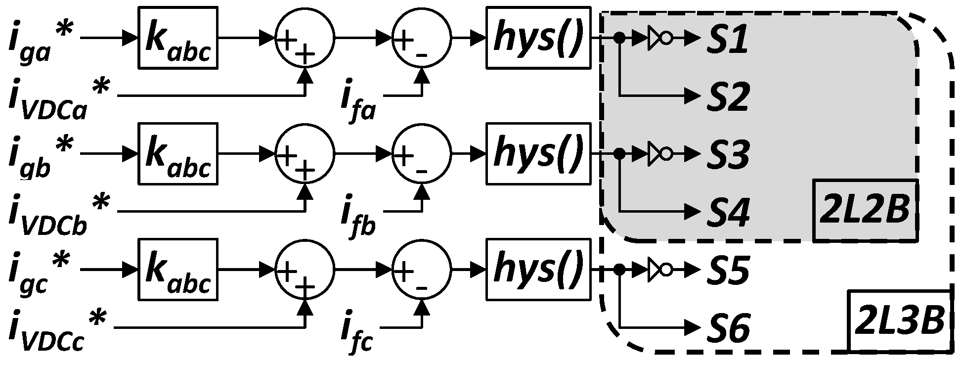
5.3. Hysteresis Band Modulation Technique

Using Figure 5 as reference, and from [39], a direct control method for the GSC currents can be established by analyzing (6) for only phases a and b in the 2L2B topology. Thus, by choosing the equation related to phase a, i f a measured is considered positive, if it flows into the converter. This way, it is noticeable that the switching states for S 1 and S 2 are dependent of v g a N , i f a and d ( i f a ) / d t . The functions s i g n ( ) and h y s ( ) are defined in (39) and (41), respectively, and are implemented in dSPACE for experimental results.
s i g n ( A ) = 0 A 0 , s i g n ( A ) = 1 A > 0 , A = ( v g a N , i f a ) .
The error variable for i f a is defined in (40). By applying (40) to (41), d ( i f a ) / d t can be determined based on the variation of i ˜ f a within the upper ( + l i m ) and lower ( l i m ) bands.
i ˜ f a = Δ i f a = i f a i f a .
h y s ( i ˜ f a ) = 0 i ˜ f a < l i m , h y s ( i ˜ f a ) = 1 i ˜ f a > + l i m , h y s ( i ˜ f a ) = n c l i m < i ˜ f a < + l i m ,
where n c means “no change”.
Applying (39) to i f a and substituting (40) into (41), the four possible combinations for i f a and d ( i f a ) / d t are expressed in (42).
s i g n ( i f a ) = 0 i ˜ f a = i f a ( i f a ) = i f a + i f a : h y s ( i ˜ f a ) = 0 i f a + i f a < l i m i f a < l i m i f a i f a i n c r e a s e s h y s ( i ˜ f a ) = 1 i f a + i f a > + l i m i f a > + l i m i f a i f a d e c r e a s e s s i g n ( i f a ) = 1 i ˜ f a = i f a i f a : h y s ( i ˜ f a ) = 0 i f a i f a < l i m i f a > + l i m + i f a i f a d e c r e a s e s h y s ( i ˜ f a ) = 1 i f a i f a > + l i m i f a > l i m + i f a i f a i n c r e a s e s
By applying (39) to v g a N and i f a , and making use of (41) and (42), Table 2 is constructed by analyzing (6) for phase a. The logic expression to directly control i f a is expressed in (43).
S 1 = a ¯ · b ¯ · c ¯ + a ¯ · b · c ¯ + a · b ¯ · c ¯ + a · b · c ¯ = c ¯ .
Figure 7 illustrates the application of the hysteresis modulation technique. In this figure, it is observed that the method can be applied to the GSC with either 2L2B or 2L3B topology. If the latter is considered, it would be necessary to take into account phase c, since the entire 2L2B analysis was realized with phase equations.

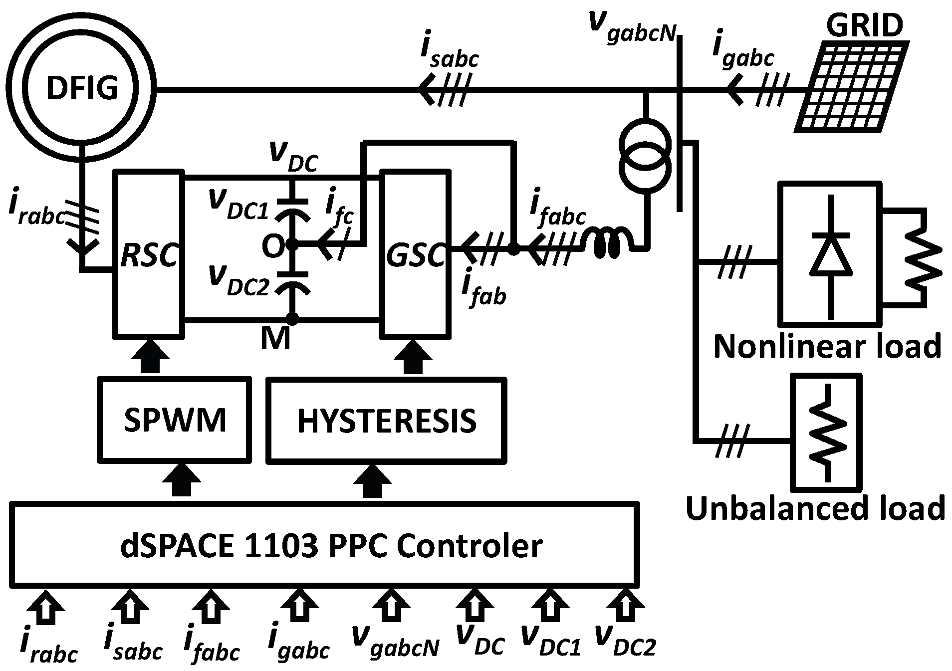
6. Experimental Setup and Experimental Results

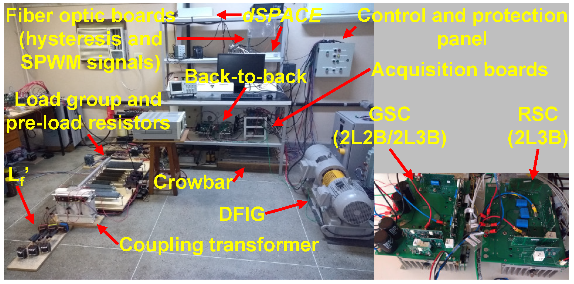
6.1. Experimental Setup

The experimental setup, Figure 9, is based on the schematic shown in Figure 1, and the main technical data are informed in Table 3. The GSC consists of a 2L3B topology converter, whose third arm is disabled and the phase c is connected to the central point of the DC link, for tests of the GSC with 2L2B topology. For tests of the GSC with 2L3B topology, the signals S 5 and S 6 , Figure 7, are enabled and the phase c is connected to the third branch. The coupling transformer is used to bypass the limitations of the breakdown voltage of the converter switches and the voltage nominal of the capacitors C 1 and C 2 , in 2L2B configuration. The entrance impedance Z f , considered in both tests with 2L2B and with 2L3B, is determined by the coupling transformer and by the L f inductors. However, it should be noted that in the 2L3B configuration there is no need for the coupling transformer. Thus, in both cases, GSC with 2L2B or 2L3B topology, the static gain ratio of 1.02 was maintained between the line voltage, at the GSC terminals, and the DC-link output voltage, v D C .

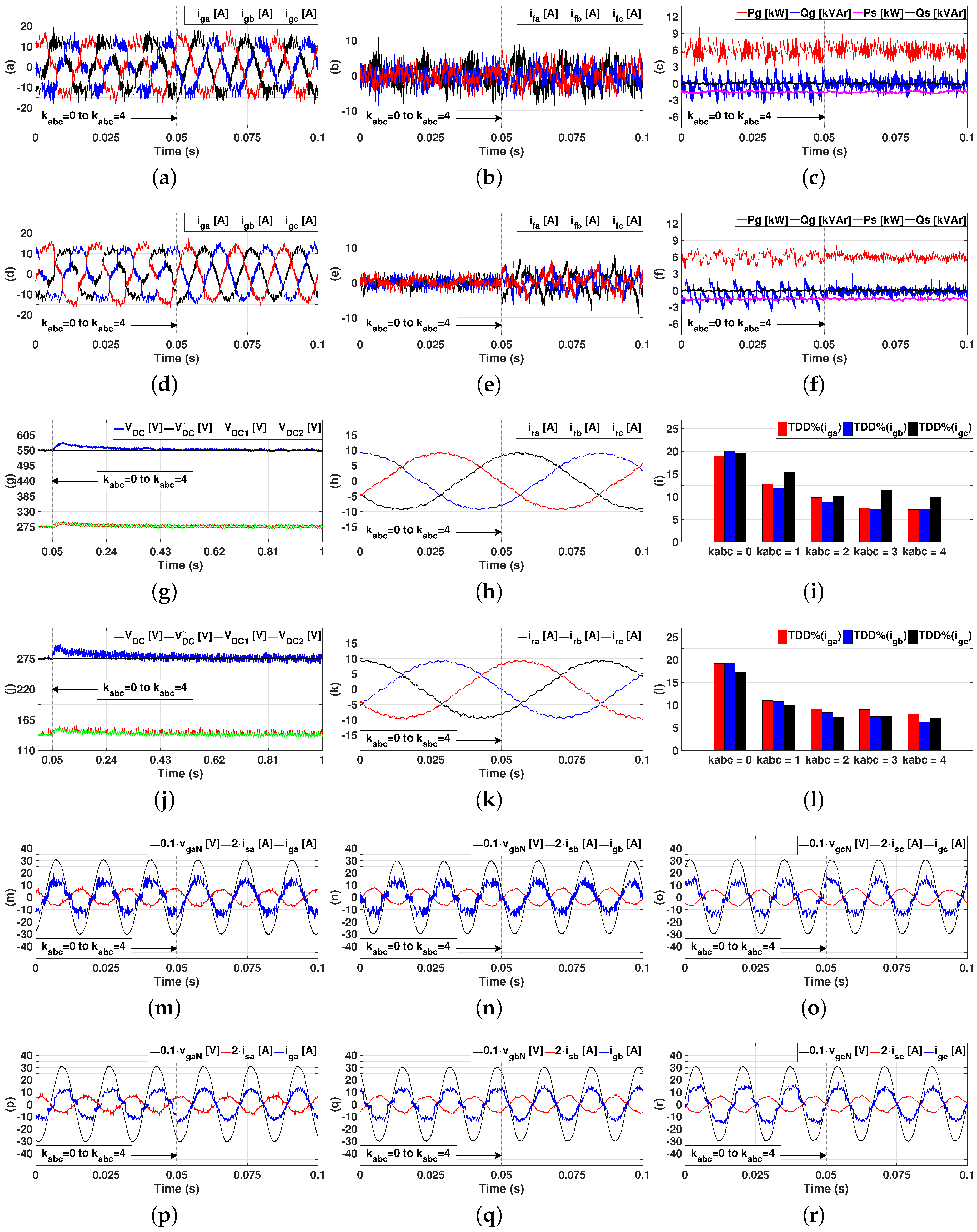
6.2. Experimental Results

Figure 10 shows the experimental results obtained with the proposed 2L2B topology for the GSC, compared to the usual topology 2L3B. For each topology, the effect of the compensation constant k a b c was evaluated for the values 0, 1, 2, 3, and 4. The highest value of k a b c was 4 due to the design limitations of the passive elements between the GSC and the grid. In all cases it was observed that the GSC with 2L2B topology presented a higher harmonic distortion at high frequencies in the grid currents. This result justifies the high-frequency oscillations present in P g and Q g with the 2L2B, both with k a b c = 0 and k a b c = 4 . This behavior is due to the fact that the 2L2B topology imposes a d v / d t at least twice greater than the 2L3B topology in the operation of the switches, because of the connection of the phase c to the midpoint of the DC link of the GSC. Therefore, for the same static gain between the input and output voltages of the GSC, the 2L2B requires more current for its operation than the 2L3B, as can be seen in Figure 10b,e. The GSC currents with the 2L2B are greater than with the 2L3B configuration, with a difference of 2 A R M S for k a b c = 0 . As k a b c increases, the difference among the currents of both topologies decreases, being less than 1 A R M S for k a b c = 4 . This effect is due to the fact that k a b c interferes only with the power conditioning action of the GSC, and not with DC-link regulation. If the same voltage were regulated for the DC link, in both 2L2B and 2L3B cases, the switching losses with the 2L3B would be 1.5 times greater than with 2L2B [34].
In the transition from k a b c = 0 to k a b c = 4 , Figure 10c,f, the GSC with 2L2B topology reduced P g from 6.118 kW to 5.965 kW and Q g from 1.549 kvar to 0.918 kvar. With the 2L3B topology, the GSC reduced P g from 5.916 kW to 5.855 kW and Q g from 1.491 kvar to 0.609 kvar. With a higher d v / d t over the switches, the power conditioning performance of the GSC with 2L2B topology is compromised and the active power necessary to maintain the DC-link voltage increases compared to the 2L3B. The 2L2B raised the power factor, from the grid point of view, from 0.969 to 0.988, while the 2L3B topology raised from 0.970 to 0.995, although Figure 10i,l show that the GSC with 2L2B topology presented more harmonic distortion for the currents i g a b c . These results show that the GSC can regulate the overall power flow in the grid without any action by the DFIG, through the RSC. This action can be performed by the GSC, both with the proposed topology 2L2B and with the usual 2L3B. Another important fact, observed in Figure 10c,f,h,k, is that the stator powers, P S and Q S , and rotor currents, i r a b c , are not influenced by the GSC topology and the value of k a b c .
The total demand distortion (TDD) values of the currents i g a b c in Figure 10i,l were obtained from the Yokogawa PZ4000 power analyzer, configured to measure the TDD of integer order harmonics up to the 50th order [50]. Considering the interharmonics and integer order harmonics up to the 50th order, the total harmonic distortion (THD) values of the currents i g a b c reduce when compensation gain k a b c increases from 0 to 4 for both topologies, as shown in Table 4.
The equivalent capacitance (from the point of view of the positive and negative pole of the converter) for the 2L2B and 2L3B topologies are, respectively, 680 μ F and 340 μ F. This justifies the voltage oscillation at the DC link of 2.58 %, with the 2L2B topology, and 7.85 %, with the 2L3B topology, as can be seen in Figure 10g,j. Figure 10g shows the overall voltage regulation at the DC link for the 2L2B topology, while keeping v D C 1 and v D C 2 balanced.
Figure 10m–o show the power conditioning action taking place as the grid currents i g a b c are in phase with their respective grid voltages v g a b c N . These results also show the stator currents i s a b c in opposition to the respective voltages v g a b c N of 180 , characterizing the injection of −1.5 kW and 0 kvar from the DFIG to the grid. Once again, it is possible to note through the currents i s a b c that the compensating action of the GSC and the topology adopted for the GSC do not interfere in the performance of the DFIG. The same conclusion can be drawn from Figure 10p–r for the GSC with the 2L3B topology.

6.3. Comparative Analysis Between the 2L2B and 2L3B Topologies

Making a general summary of the positives and negatives aspects of the use of the 2L2B topology as GSC in Type III WTG regarding to the 2L3B topology, it is possible to better compare the topologies. An overview about the points related to the experimental results, constructive details, operational risks/problems and operational advantages of the 2L2B topology in relation to 2L3B topology are presented in Table 5.

7. Conclusions

This work presents a study on the operational feasibility of a GSC with reduced number of switches for DFIG-based WTG. Experimental tests were carried out using a DFIG with rated power of 8 kVA, in which about 20% of the nominal power of the back-to-back converter was necessary to maintain the DFIG operating with 18.75% of its capacity. The effectiveness of the 2L2B topology is assessed in a scenario where ancillary services, namely harmonics filtering and reactive power compensation, are provided, while regulating the DC-link voltage. These results are compared to the more usual 2L3B topology.
The study concluded that for the same static gain among the input and output voltages of the GSC, the 2L3B topology showed a better performance in the reduction of reactive power and oscillating active power, and in the reduction of the TDD of the grid currents. However, the experimental results for the 2L2B topology showed a certain proximity to the 2L3B topology. Due to the strong grid characteristic at the common connection point of the experimental setup (not common for wind farms located in remote areas), the performance of the 2L2B and 2L3B topologies with respect to harmonic filtering may be acceptable for a real application. According to [50], strong grids have high short-circuit capacities. This factor implies greater limits of current harmonic distortion acceptable in the electrical grid under analysis. Thus, it is possible to affirm that the 2L2B topology can replace the conventional topology 2L3B without any significant loss of harmonic filtering performance. In addition, the reduced number of switches, drives, and snubbers circuits, for example, involved in the construction of the GSC in the 2L2B configuration, reduces construction and maintenance costs. The reduction of the costs of operation can be observed through the reduced use of auxiliary power supplies of lower power for the drivers of the back-to-back converter. However, there are negative points to be observed regarding the use of the 2L2B topology as GSC in place of the 2L3B topology. In Section 6.3, was presented a summary of the main negative and positive points associated with the 2L2B topology in relation to the 2L3B topology. These characteristics are associated with the fact that the use of 2L2B, as a GSC, did not interfere in the operation of the DFIG and RSC, and validated the proposal of this work concerning the employability of 2L2B topology in Type III WTG. Thus, the use of AC–DC converters with only two controlled branches can become an interesting option for DFIG-based WTG.

Author Contributions

Conceptualization, E.E.C.M. and F.K.d.A.L.; methodology, E.E.C.M. and F.K.d.A.L.; validation, E.E.C.M.; formal analysis, E.E.C.M. and J.M.L.F.; investigation, E.E.C.M.; data curation, E.E.C.M. and J.M.L.F.; writing–original draft preparation, E.E.C.M.; writing–review and editing, F.K.d.A.L., J.M.L.F. and L.d.A.M.; visualization, J.M.L.F. and L.d.A.M.; supervision, F.K.d.A.L. and C.G.C.B.; project administration, E.E.C.M.

Funding

This research received no external funding.

Acknowledgments

The authors thank the Department of Electrical of Engineering of Federal University of Ceara and the Laboratory of Applications of Power Electronics and Integration to Energy Systems (LAPIS) for the support to carry out the experiments.

Conflicts of Interest

The authors declare no conflict of interest.

References

  1. Sawyer, S.; Liming, Q.; Fried, L. GLOBAL WIND REPORT— Annual Market Update 2017; Global Wind Energy Council: Brussels, Belgium, 2017. [Google Scholar]
  2. Kim, H.S.; Lu, D.D. Review on wind turbine generators and power electronic converters with the grid-connection issues. In Proceedings of the 2010 20th Australasian Universities Power Engineering Conference, Christchurch, New Zealand, 5–8 December 2010; pp. 1–6. [Google Scholar]
  3. Guerrero, J.M.; Blaabjerg, F.; Zhelev, T.; Hemmes, K.; Monmasson, E.; Jemei, S.; Comech, M.P.; Granadino, R.; Frau, J.I. Distributed Generation: Toward a New Energy Paradigm. IEEE Ind. Electron. Mag. 2010, 4, 52–64. [Google Scholar] [CrossRef]
  4. Yaramasu, V.; Wu, B.; Sen, P.C.; Kouro, S.; Narimani, M. High-power wind energy conversion systems: State-of-the-art and emerging technologies. Proc. IEEE 2015, 103, 740–788. [Google Scholar] [CrossRef]
  5. Blaabjerg, F.; Liserre, M.; Ma, K. Power Electronics Converters for Wind Turbine Systems. IEEE Trans. Ind. Appl. 2012, 48, 708–719. [Google Scholar] [CrossRef]
  6. Leon, A.E.; Mauricio, J.M.; Solsona, J.A. Fault Ride-Through Enhancement of DFIG-Based Wind Generation Considering Unbalanced and Distorted Conditions. IEEE Trans. Energy Convers. 2012, 27, 775–783. [Google Scholar] [CrossRef]
  7. Djurović, S.; Vilchis-Rodriguez, D.S.; Smith, A.C. Supply Induced Interharmonic Effects in Wound Rotor and Doubly-Fed Induction Generators. IEEE Trans. Energy Convers. 2015, 30, 1397–1408. [Google Scholar] [CrossRef]
  8. Yan, S.; Zhang, A.; Zhang, H.; Wang, J.; Cai, B. An Optimum Design for a DC-Based DFIG System by Regulating Gearbox Ratio. IEEE Trans. Energy Convers. 2018, 33, 223–231. [Google Scholar] [CrossRef]
  9. Tentzerakis, S.T.; Papathanassiou, S.A. An Investigation of the Harmonic Emissions of Wind Turbines. IEEE Trans. Energy Convers. 2007, 22, 150–158. [Google Scholar] [CrossRef]
  10. Song, Y.; Nian, H. Enhanced Grid-Connected Operation of DFIG Using Improved Repetitive Control Under Generalized Harmonic Power Grid. IEEE Trans. Energy Convers. 2015, 30, 1019–1029. [Google Scholar] [CrossRef]
  11. Swami Naidu, N.K.; Singh, B. Doubly Fed Induction Generator for Wind Energy Conversion Systems with Integrated Active Filter Capabilities. IEEE Trans. Ind. Inform. 2015, 11, 923–933. [Google Scholar] [CrossRef]
  12. Xu, H.; Hu, J.; He, Y. Integrated Modeling and Enhanced Control of DFIG Under Unbalanced and Distorted Grid Voltage Conditions. IEEE Trans. Energy Convers. 2012, 27, 725–736. [Google Scholar] [CrossRef]
  13. Xu, H.; Hu, J.; He, Y. Operation of Wind-Turbine-Driven DFIG Systems Under Distorted Grid Voltage Conditions: Analysis and Experimental Validations. IEEE Trans. Power Electron. 2012, 27, 2354–2366. [Google Scholar] [CrossRef]
  14. Hu, J.; Xu, H.; He, Y. Coordinated Control of DFIG’s RSC and GSC Under Generalized Unbalanced and Distorted Grid Voltage Conditions. IEEE Trans. Ind. Electron. 2013, 60, 2808–2819. [Google Scholar] [CrossRef]
  15. Larose, C.; Gagnon, R.; Prud’Homme, P.; Fecteau, M.; Asmine, M. Type-III Wind Power Plant Harmonic Emissions: Field Measurements and Aggregation Guidelines for Adequate Representation of Harmonics. IEEE Trans. Sustain. Energy 2013, 4, 797–804. [Google Scholar] [CrossRef]
  16. Blaabjerg, F.; Ma, K. Future on Power Electronics for Wind Turbine Systems. IEEE J. Emerg. Sel. Top. Power Electron. 2013, 1, 139–152. [Google Scholar] [CrossRef]
  17. Sujod, M.Z.; Erlich, I. A new protection scheme for three-level NPC converter based DFIG using zero state control. In Proceedings of the IEEE PES ISGT Europe 2013, Lyngby, Denmark, 6–9 October 2013; pp. 1–5. [Google Scholar] [CrossRef]
  18. Liao, Y.; Li, R.; Putrus, G.A.; Smith, K.S. Evaluation of the effects of rotor harmonics in a doubly-fed induction generator with harmonic induced speed ripple. IEEE Trans. Energy Convers. 2003, 18, 508–515. [Google Scholar] [CrossRef]
  19. Nian, H.; Song, Y. Direct Power Control of Doubly Fed Induction Generator Under Distorted Grid Voltage. IEEE Trans. Power Electron. 2014, 29, 894–905. [Google Scholar] [CrossRef]
  20. Song, Y.; Nian, H. Modularized Control Strategy and Performance Analysis of DFIG System Under Unbalanced and Harmonic Grid Voltage. IEEE Trans. Power Electron. 2015, 30, 4831–4842. [Google Scholar] [CrossRef]
  21. Djurović, S.; Williamson, S. Influence of supply harmonic voltages on DFIG stator current and power spectrum. In Proceedings of the The XIX International Conference on Electrical Machines—ICEM 2010, Rome, Italy, 6–8 September 2010; pp. 1–6. [Google Scholar] [CrossRef]
  22. Song, Y.; Nian, H. Sinusoidal Output Current Implementation of DFIG Using Repetitive Control Under a Generalized Harmonic Power Grid with Frequency Deviation. IEEE Trans. Power Electron. 2015, 30, 6751–6762. [Google Scholar] [CrossRef]
  23. Wei, F.; Zhang, X.; Vilathgamuwa, D.M.; Choi, S.S.; Wang, S. Mitigation of distorted and unbalanced stator voltage of stand-alone doubly fed induction generators using repetitive control technique. IET Electr. Power Appl. 2013, 7, 654–663. [Google Scholar] [CrossRef]
  24. Liu, C.; Blaabjerg, F.; Chen, W.; Xu, D. Stator Current Harmonic Control with Resonant Controller for Doubly Fed Induction Generator. IEEE Trans. Power Electron. 2012, 27, 3207–3220. [Google Scholar] [CrossRef]
  25. Nian, H.; Song, Y. Optimised parameter design of proportional integral and resonant current regulator for doubly fed induction generator during grid voltage distortion. IET Renew. Power Gener. 2014, 8, 299–313. [Google Scholar] [CrossRef]
  26. Phan, V.; Lee, H. Control Strategy for Harmonic Elimination in Stand-Alone DFIG Applications with Nonlinear Loads. IEEE Trans. Power Electron. 2011, 26, 2662–2675. [Google Scholar] [CrossRef]
  27. Phan, V.; Lee, H. Stationary frame control scheme for a stand-alone doubly fed induction generator system with effective harmonic voltages rejection. IET Electr. Power Appl. 2011, 5, 697–707. [Google Scholar] [CrossRef]
  28. Sun, D.; Zhou, W. Adaptive PWM for four-switch three-phase inverter. Electron. Lett. 2015, 51. [Google Scholar] [CrossRef]
  29. Singh, B.; Singh, B.N.; Chandra, A.; Al-Haddad, K.; Pandey, A.; Kothari, D.P. A review of three-phase improved power quality AC-DC converters. IEEE Trans. Ind. Electron. 2004, 51, 641–660. [Google Scholar] [CrossRef]
  30. Bala, S.; Patel, N.; Femandes, B.G. Reduced-switch three-phase active power filter with one cycle control. In Proceedings of the 2004 IEEE 35th Annual Power Electronics Specialists Conference (IEEE Cat. No.04CH37551), Aachen, Germany, 20–25 June 2004; Volume 3, pp. 2333–2339. [Google Scholar] [CrossRef]
  31. Hsan, K.; Rmili, L.; Rahmani, S.; Al-Haddad, K. A nonlinear control applied to a shunt hybrid power filter with two arms and a midpoint capacitor. In Proceedings of the 2013 IEEE International Symposium on Industrial Electronics, Taipei, Taiwan, 28–31 May 2013; pp. 1–6. [Google Scholar] [CrossRef]
  32. Singh, B.N.; Singh, B.; Chandra, A.; Rastgoufard, P.; Al-Haddad, K. An Improved Control Algorithm for Active Filters. IEEE Trans. Power Deliv. 2007, 22, 1009–1020. [Google Scholar] [CrossRef]
  33. Valouch, V.; Škramlík, J.; Muller, Z.; Švec, J.; Tlustý, J. Optimized half a period switching symmetry applied at grid connected four-switch converter and analytical solution of steady states. In Proceedings of the 2014 16th International Power Electronics and Motion Control Conference and Exposition, Antalya, Turkey, 21–24 September 2014; pp. 125–130. [Google Scholar] [CrossRef]
  34. Haddad, K.; Joos, G. Three phase active filter topology based on a reduced switch count voltage source inverter. In Proceedings of the 30th Annual IEEE Power Electronics Specialists Conference. Record. (Cat. No.99CH36321), Charleston, SC, USA, 1 July 1999; Volume 1, pp. 236–241. [Google Scholar] [CrossRef]
  35. Arani, A.D.; Aslinezhad, M.H.; Doremami, A.; Soleimanian, D. Introducing a new circuit configuration for three-phase series active power filter to use in electricity distribution networks. In Proceedings of the 2012 Proceedings of 17th Conference on Electrical Power Distribution, Tehran, Iran, 2–3 May 2012; pp. 1–6. [Google Scholar]
  36. Wu, J.; Jou, H.; Feng, Y.; Hsu, W.; Huang, M.; Hou, W. Novel Circuit Topology for Three-Phase Active Power Filter. IEEE Trans. Power Deliv. 2007, 22, 444–449. [Google Scholar] [CrossRef]
  37. Klima, J.; Tlusty, J.; Škramlík, J.; Valouch, V. Analytical Model and Investigation of a Four-Switch Space-Vector Modulated Hybrid Power Filter with SixFold Switching Symmetry. Renew. Energy Power Qual. J. 2009, 1. [Google Scholar] [CrossRef]
  38. Lin, B.R.; Wei, T.C. A novel NPC inverter for harmonics elimination and reactive power compensation. IEEE Trans. Power Deliv. 2004, 19, 1449–1456. [Google Scholar] [CrossRef]
  39. Lin, B.R.; Chiang, H.K.; Huang, C.H. Three-phase three-level active power filter with a clamped capacitor topology. IEE Proc. Electr. Power Appl. 2006, 153, 513–522. [Google Scholar] [CrossRef]
  40. Su, J.; Sun, D. Simplified MPCC for four-switch three-phase inverter-fed PMSM. Electron. Lett. 2017, 53, 1108–1109. [Google Scholar] [CrossRef]
  41. Sun, D.; He, Z.; He, Y.; Guan, Y. Four-Switch Inverter Fed PMSM DTC with SVM approach for Fault Tolerant operation. In Proceedings of the 2007 IEEE International Electric Machines Drives Conference, Antalya, Turkey, 3–5 May 2007; Volume 1, pp. 295–299. [Google Scholar] [CrossRef]
  42. Gi-Taek, K.; Lipo, T.A. VSI-PWM rectifier/inverter system with a reduced switch count. IEEE Trans. Ind. Appl. 1996, 32, 1331–1337. [Google Scholar] [CrossRef]
  43. Izanlo, A.; Asghar Gholamian, S.; Kazemi, M. Using of four-switch three-phase converter in the structure DPC of DFIG under unbalanced grid voltage condition. Electr. Eng. 2017. [Google Scholar] [CrossRef]
  44. Lin, B.; Chen, J. Three-Phase Two-Leg Inverter for Stand-Alone and Grid-Connected Renewable Energy Systems. In Proceedings of the TENCON 2006—2006 IEEE Region 10 Conference, Hong Kong, China, 14–17 November 2006; pp. 1–4. [Google Scholar] [CrossRef]
  45. Ni, K.; Hu, Y.; Liu, Y.; Gan, C. Performance Analysis of a Four-Switch Three-Phase Grid-Side Converter with Modulation Simplification in a Doubly-Fed Induction Generator-Based Wind Turbine (DFIG-WT) with Different External Disturbances. Energies 2017, 10, 706. [Google Scholar] [CrossRef]
  46. Teodorescu, R.; Liserre, M.; Rodriguez, P. Grid Converters for Photovoltaic and Wind Power Systems; Wiley-IEEE: John Wiley & Sons: Hoboken, NJ, USA, 2011. [Google Scholar]
  47. Leonhard, W. Control of Electrical Drives; Power Systems; Springer: Berlin/Heidelberg, Germany, 2012. [Google Scholar]
  48. Abad, G.; López, J.; Rodríguez, M.; Marroyo, L.; Iwanski, G. Doubly Fed Induction Machine: Modeling and Control for Wind Energy Generation Applications. In Appendix; John Wiley & Sons: Hoboken, NJ, USA, 2011. [Google Scholar] [CrossRef]
  49. Akagi, H.; Kanazawa, Y.; Nabae, A. Instantaneous Reactive Power Compensators Comprising Switching Devices without Energy Storage Components. IEEE Trans. Ind. Appl. 1984, IA-20, 625–630. [Google Scholar] [CrossRef]
  50. IEEE. 519-2014—IEEE Recommended Practice and Requirements for Harmonic Control in Electric Power Systems. In IEEE Std 519-2014 (Revision of IEEE Std 519-1992); IEEE: Piscataway, New Jersey, USA, 2014; pp. 1–29. [Google Scholar] [CrossRef]
Figure 1. Type III WTG System with 2L2B Topology as GSC.
Energies 12 02490 g001
Figure 2. Detailed GSC structure. (a) 2L2B proposed; (b) 2L3B usual.
Energies 12 02490 g002
Figure 3. Detailing the synchronization system. (a) Static and synchronous reference frames; (b) Synchronization system structure.
Energies 12 02490 g003
Figure 4. RSC control strategy. θ S is the slip angle or rotor electrical angle.
Energies 12 02490 g004
Figure 5. Simplified schematic of the GSC.
Energies 12 02490 g005
Figure 6. Harmonic filtering and reactive power compensation strategy.
Energies 12 02490 g006
Figure 7. Hysteresis modulation technique applied to the GSC.
Energies 12 02490 g007
Figure 8. DC-link regulation strategy.
Energies 12 02490 g008
Figure 9. Experimental setup.
Energies 12 02490 g009
Figure 10. Experimental results for the 2L2B topology: (a) Grid currents; (b) GSC currents; (c) grid/stator active and reactive power; (g) DC-link voltages; (h) rotor currents; (i) grid currents TDD; and grid/stator currents and phase voltages in phase a (m), phase b (n) and phase c (o). Experimental results for the 2L3B topology: (d) Grid currents; (e) GSC currents; (f) grid/stator active and reactive power; (j) DC-link voltages; (k) rotor currents; (l) grid currents TDD, and grid/stator currents and phase voltages in phase a (p), phase b (q) and phase c (r).
Energies 12 02490 g010
Table 1. Voltage levels at the GSC terminals in different operation stages.
S1 = 0/S3 = 0S1 = 1/S3 = 0S1 = 1/S3 = 0S1 = 1/S3 = 1
v f a M 00 V D C V D C
v f b M 0 V D C 0 V D C
v f c M     V D C / 2     V D C / 2     V D C / 2     V D C / 2
v M N V D C / 6 V D C / 2 V D C / 2 5 V D C / 6
v f a N V D C / 6 V D C / 2     V D C / 2     V D C / 6
v f b N V D C / 6     V D C / 2 V D C / 2     V D C / 6
v f c N     V D C / 3 00 V D C / 3
Table 2. Truth table for the switching states of S 1 ( S 1 = S 2 ¯ ).
Switching StateabcS1
sign ( v gaN ) sign ( i fa ) hys ( i ˜ fa )
SS10001
SS20010
SS30101
SS40110
SS51001
SS61010
SS71101
SS81110
Table 3. Experimental setup parameters.
DFIG (8 kVA/4 poles)
Operation Mode/SlipSub-synchronous/20%
Stator Reference Power P s = 1.5 kW/ Q s = 0 kvar
Back-to-Back Converter (4.5 kVA)
IGBTIRG4PF50WD
C 1 and C 2 680  μ F/400 V
RSC Switching Frequency10 kHz
v D C 550 Vdc (2L2B)/275 Vdc (2L3B)
GSC Input Impedance Z f
Coupling Transformer5 kVA/2.22%/Y-Y(380 V-190 V)
L f 1 mH
Group of Linear and Nonlinear Loads
Linear Load (3 Resistors)0.75 kW/1.0 kW/1.5 kW
Nonlinear Load (3- ϕ rectifier)3.7 kW
Table 4. Reduction of THD of the i g a b c currents with the increase of the k a b c gain for both topologies.
2L2B Topology2L3B Topology
T H D % i g a b c k a b c = 0 Phase aPhase bPhase cPhase aPhase bPhase c
23.325.824.821.120.819.0
T H D % i g a b c k a b c = 4 Phase aPhase bPhase cPhase aPhase bPhase c
13.713.315.411.510.110.0
Table 5. Overview of the advantages and disadvantages of 2L2B topology as GSC in Type III WTG regarding 2L3B topology.
Negative PointsPositive Points
Experimental Results
  • It presented higher high-frequency harmonic content for the grid currents;
  • Due to the operation with high voltage in the DC bus, the current processed by the GSC was higher;
  • It presented greater oscillations in the active and reactive powers of the grid.
  • It showed lower voltage ripple on the DC bus;
  • It presented a performance of compensation of the reactive power and oscillating active power near the 2L3B topology, using the same control strategy;
  • It presented a TDD reduction of the grid currents close to the obtained with the 2L3B topology. Approximately 10% of k a b c = 0 to k a b c = 4 for both topologies.
Construction Details
  • The DC bus voltage must be at least two times higher;
  • Requires two capacitors;
  • The GSC input inductances are greater;
  • Requires switches with higher blocking voltages and power dissipation capability. Therefore, switches more expensive.
  • For the same capacitances used in the DC-link construction of the back-to-back converter, the 2L2B topology has a higher equivalent capacitance among the phases;
  • Using switches with greater power dissipation capability and with reduced quantity, the total conduction losses and total switching losses of the back-to-back converter are lower;
  • Still due to the switches with greater power dissipation capability, the switches failure rate is smaller. Therefore, the mean time between failures and the life expectancy of the switches of the back-to-back converter are greater;
  • Need for fewer drivers to the switches and fewer snubber circuits. Thus, the auxiliary power supplies of the converter may be of lower power.
Operational Characteristics
Risks and Problems
  • Failure of a switch of the GSC is difficult to overcome, leading to immediate disconnection of the drive if there is no appropriate protection system;
  • It does not have the same robustness of a conventional back-to-back converter for the insulation of the propagation of voltage disturbances between the grid and the rotor circuit.
Advantages
  • The total reduction of costs of the back-to-back converter allows the employment of other structural resources for increases the your protection and improvement of the operational performance (such as the use of LCL passive filters).

