Effects of the Aspect Ratio of a Rectangular Thermosyphon on Its Thermal Performance


1
Department of Architecture, National Cheng Kung University, Tainan 701, Taiwan
2
Department of Mechanical Engineering, Southern Taiwan University of Science and Technology, Tainan 710, Taiwan
3
Department of Civil Engineering, National Cheng Kung University, Tainan 701, Taiwan
*
Author to whom correspondence should be addressed.
Energies 2019, 12(20), 4014; https://0-doi-org.brum.beds.ac.uk/10.3390/en12204014
Submission received: 13 September 2019
/
Revised: 17 October 2019
/
Accepted: 20 October 2019
/
Published: 22 October 2019
(This article belongs to the Special Issue Building Thermal Envelope)
Abstract
:The natural convection behaviors of rectangular thermosyphons with different aspect ratios were experimentally analyzed in this study. The experimental model consisted of a loop body, a heating section, a cooling section, and adiabatic sections. The heating and cooling sections were located in the vertical portions of the rectangular loop. The length of the vertical cooling section and the lengths of the upper and lower adiabatic sections were fixed at 300 mm and 200 mm, respectively. The inner diameter of the loop was fixed at 11 mm, and the cooling end temperature was 30 °C. The relevant parameters and their ranges were as follows: The aspect ratios were 6, 4.5, and 3.5 (with potential differences of 41, 27, and 18, respectively, between the cold and hot ends), and the input thermal power ranged from 30 to 60 W (with a heat flux of 600 to 3800 W/m2). The results show that it is feasible to obtain solar heat gain by installing a rectangular thermosyphon inside the metal curtain wall and that increasing the height of the opaque part of the metal curtain wall can increase the aspect ratio of the rectangular thermosyphon installed inside the wall and thus improve the heat transfer efficiency.
1. Introduction
A thermosyphon is a type of natural circulation loop. It relies on the proper arrangement of the heating zone and cooling zone to cause a change in the density of the fluid within the loop, and the resulting thermal buoyancy drives the working fluid to transfer thermal energy. The cooling section and the heating section are usually placed either above and below the loop or on the left and right sides of the loop. When the working fluid is heated in the heating section, its density decreases, generating thermal buoyancy and driving it to flow upward and dissipate heat in the cooling section. Gravity resists the upward flow of the working fluid and helps its downward flow (when the flow is in the same direction as gravity). Because no external driving force is required, thermosyphons have considerable operational reliability. This self-adjusting mechanism and stability have led thermosyphons to be used in a wide range of applications, such as solar heating and cooling systems, coolers for nuclear power plant reactors, geothermal energy systems, waste heat recovery systems, and electronic cooling systems. There are many considerations in the design of a thermosyphon with good thermal efficiency, including the choices of the working fluid and wall material, the locations of the heating and cooling sections, and the geometric parameters of the loop. Studies of the performance of natural convection loops and the effects of various parameters can be found in the existing literature [1,2,3].
Ismail and Abogderah [4] compared the theoretical predictions with experimental results of a flat-plate solar collector with heat pipes as energy transport. The experimental results of the proposed solar collector were also compared with a conventional commercial solar collector. The results showed that the instantaneous efficiencies of the proposed collector are lower than the conventional one in the morning and higher when the heat pipes reach their operating temperatures. Mathioulakis and Belessiotis [5] theoretically and experimentally studied the thermal performance of a solar water system with an integrated wickless gravity assisted loop heat pipe. The results validated a theoretical model for the collector that can be used for the optimization of the system design. Misale et al. [6] analyzed the influence of thermal boundary conditions on the flow regimes inside the pipes and the stability of the thermosyphon. Their results showed that the higher the heating power is, the greater the flow rate is. However, after the flow becomes a two-phase flow, the flow rate decreases due to the formation of bubbles, and an increase in the height difference of the loop also increases the flow rate and heat transfer gain.
Lai et al. [7] explored the thermal performance of a rectangular natural circulation loop. The results showed that the average velocity of the fluid increases with an increase in the heating power and aspect ratio or a decrease in the length of the cooling section. Desrayaud et al. [8] numerically investigated the thermal behavior of a rectangular natural circulation loop with horizontal heat exchangers. It was shown that the vortices result in the occurrence of the oscillations and cause the growth of temperature gradients. Huminic and Huminic [9] numerically investigated the nanofluid heat transfer in thermosyphon heat pipes. The results showed that using the nanofluid has better heat transfer characteristics than using water and the volume concentration of nanoparticles has a significant effect in reducing the temperature difference between the evaporator and condenser. Martinopoulos et al. [10] experimentally evaluated the thermal performance and the optimization parameters of a phase-change flat plate solar collector. The collector with a 50% volume filament at a 40° inclination showed a better system efficiency that increased proportionally with the increased mass flow rates.
Ho et al. [11] obtained the relationship between the Rayleigh number (Ra) and the Reynolds number (Re), as well as the Nusselt number (Nu) of a single-phase thermosyphon, using experiments and numerical simulations. Vijayan et al. [12] studied the effects of the heater and cooler orientations in a single-phase thermosyphon. Three oscillatory modes and instabilities were observed in the experiments. Misale et al. [13] tested thermosyphons at different inclination angles and found that the inclination angle affected the heat transfer performance and that the best performance can be achieved at an inclination angle of 0° (i.e., vertical with respect to the ground). Swapnalee and Vijayan [14] obtained the relation between Re and the Grashof number (Gr) from experiments and simulations of a single-phase thermosyphon and used the geometric parameter Ng to modify Gr to make the prediction model of the relation applicable to four different types of heating and cooling. Thomas and Sobhan [15] experimentally studied the stability and transient performance of a vertical heater-vertical cooler natural circulation loop with metal oxide nanoparticles. The results indicated that nanofluids containing aluminum oxide and copper oxide have better heat transfer performance as the working fluid than pure water. Huang et al. [16] experimentally analyzed the natural convection of a rectangular thermosyphon with an aspect ratio (AR) of 3.5. They found that the value of the dimensionless heat transfer coefficient, Nu, is generally between 5 and 10, and that the power of the heating section and the height difference between the cooling and heating sections are the main factors affecting the natural convection intensity of the thermosyphon.
The thermal performance and applications of a rectangular thermosiphon with the heating and cooling sections on the opposite vertical legs are worthy of in-depth investigation, but have rarely been studied in the literature. To the best knowledge of the authors, a study responding to the design diversity of balcony exterior walls or curtain walls via the loop aspect ratios, as shown in Figure 1, has not yet been conducted. Therefore, this study, which is a follow-up to [16], experimentally investigated the effect of the AR of a rectangular thermosyphon loop on its natural convection performance using boundary conditions of a constant heat flux and a fixed wall temperature for the heating and cooling sections, respectively, of the loop.
2. Materials and Methods
2.1. Scenarios and Test Cell Development
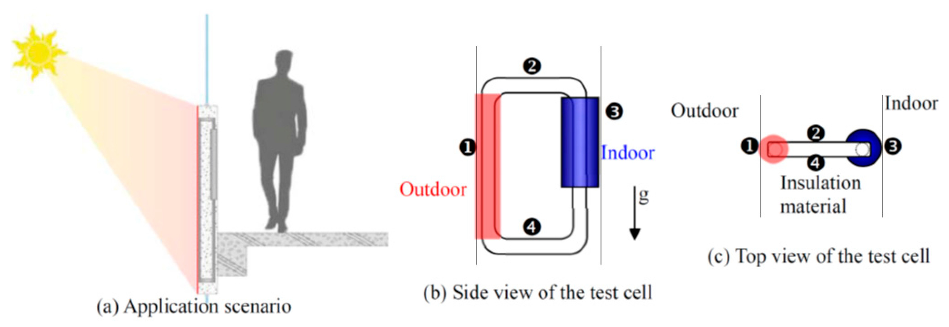
Our goal was to develop a structure within the metal curtain wall to capture solar heat energy (Figure 1a). The exterior wall of the structure that absorbs solar heat was simplified to a single vertical tube ❶ with a constant heat flux boundary. The structure was designed to be a rectangular thermosyphon to investigate its thermal performance in detail, as shown in Figure 1b,c. The heat insulation materials filled the gap between the exterior and interior walls of the structure. When hot water is required by the occupants, cold water can be fed into the heat exchanger ❸ at the indoor side. The side view in Figure 1b clearly illustrates the components of the circulation loop by removing all the heat insulation materials between the outdoor and indoor ends.
During the day, the working fluid in the circulation loop becomes a high-temperature liquid after it absorbs the solar heat from an outdoor heat source ❶. The fluid is driven by thermal buoyancy to create natural convection and then flows along the horizontal circulation branch ❷ to the indoor heat sink ❸, where heat is dissipated, and then flows under gravity along another horizontal circulation branch ❹ back to the outdoor heat source. Thus, a naturally flowing rectangular thermosyphon is formed, in which the outdoor heat source ❶ is represented by a vertical tube heated by a constant heat flux, and the indoor heat sink ❸ is the vertical section with an isothermal temperature boundary.
2.2. Experimental Test Cell
The test cell can be divided into the rectangular loop, the heating section, the cooling section, and the adiabatic sections. The heating section and the cooling section are both located in the vertical portions of the rectangular loop, as shown in Figure 2, and are introduced below.
2.2.1. Rectangular Loop
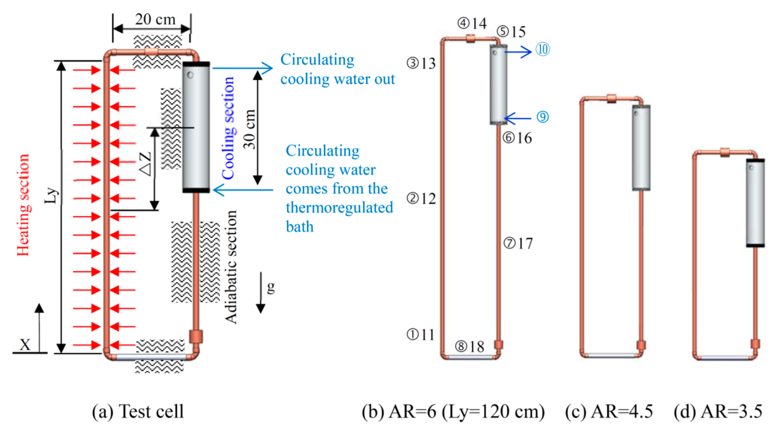
The loop in the experiment was made of red copper tube with a high thermal conductivity, and the entire loop had the same cross-sectional area. The round copper tube had an outer diameter of 12.7 mm and an inner diameter (Di) of 11 mm. The experimental test cell was installed inside the curtain wall. The lengths of the upper and lower adiabatic sections, Lx, of the experimental test cell were similar to the thickness of the curtain wall. In building practice, the thickness of the wall was approximately 200 mm with little variation. Therefore, Lx was fixed at 200 mm in this study. The length of the vertical heating section, Ly, was similar to the height of the curtain wall, and this height varied with the elevation design of the building. Therefore, Ly was set to 1200, 900, and 700 mm in this study. As a result, the ARs (AR = Ly/Lx) of the experimental test cell were 6, 4.5, and 3.5, respectively, as shown in Figure 2b–d. To investigate the influence of the geometry on the heat transfer capability of the experimental test cell, the length of the cooling end Lc was fixed at 300 mm. Therefore, the potential differences of the experimental test cell were 41, 27 and 18, respectively.
2.2.2. Heating Section
The heating section is a constant heat flux boundary for the simulation of actual applications. Therefore, the heating wire was used to generate heating at a fixed thermal power. To increase the uniformity of the heating section, the heating wire was directly processed in the heating section and was mainly composed of mica paper, heating wire, and heat insulating material. Because the tubes of the experimental test cell were made of conductive red copper, the surfaces of the copper tubes in the heating section had to be insulated before winding the heating wire around the heating section. Therefore, soft muscovite paper, which is an excellent insulator and is thermally resistant to 500 and 550 °C, was wound around the heating section for insulation. Based on the input electric power of 60 W and the maximum power supply voltage of 60 V, the electric resistance was determined to be 60 Ω. Thus, the heating wire should have a similar resistance. A 2.5 m-long heating wire with a diameter of 0.25 mm and a resistance of 25.82 Ω/m was selected for the experiment.
2.2.3. Cooling Section
The cooling section is a simulated isothermal boundary condition. The cooling water sleeve was 300 mm long and was mainly composed of a water sleeve body and two water sleeve caps. The water sleeve body was a cylinder with an outer diameter of 61 mm and an inner diameter of 40 mm. Each end of the sleeve was covered by a water sleeve cap, at the center of which was an opening with a diameter of approximately 11 mm. The thermosyphon could pass through the cooling water sleeve via these openings, and the joints were fitted with O-ring grooves to prevent leakage of the cooling water sleeve.
2.2.4. Adiabatic Sections
Other than the heating and cooling sections, the remainder of the cell was composed of the adiabatic sections. To eliminate the effects of heat loss and ambient environmental factors during the experiment, a 3 mm-thick insulating tape and a 20 mm-thick insulating pipe were wrapped around the body to effectively simulate the adiabatic boundary conditions.
2.3. Experimental Apparatus
The device and data acquisition system included a data acquisition unit (Yokogawa MX-100, Yokogawa Electric, Tokyo, Japan), a PC, a flow meter (Fluidwell F110-P, Fluidwell BV, Veghel, The Netherlands), a DC power supply unit (Gwinstek SPD-3606, GW Instek, New Taipei City, Taiwan) and a thermoregulated bath (RCB-412).
2.3.1. Power Supply System
The heating wire of the heating section was directly connected to the power supply. The output voltage and current were adjusted to provide the input electric power of 30–60 W that was required in the experiment. If we take 300 W/m2 as the nominal solar heat gain on the wall, then the service areas of each test cell are 0.1 m2 (= 30/300; = 30 W) and 0.2 m2 (= 60/300; = 60 W).
2.3.2. Thermoregulated Bath
The isothermal boundary of the cooling section was established by circulating water from the thermoregulated water bath to establish a cooling section temperature Tc of 30 °C required for the experiment.
2.3.3. Liquid Flow Meter
The flow meter was used to monitor the cooling water output by the thermoregulated bath in each set of experiments, with an average flow rate of approximately 35 mL/s.
2.3.4. Thermocouples
Type-K thermocouples were used in the experiment to measure the temperature distribution at different points along the loop, including the wall temperature and the water temperature inside the tube. A total of 18-point thermocouples was embedded in each experimental test cell at the lower, middle, and upper positions of the heating section, at the inlet and outlet of the water sleeve of the cooling section, and along the adiabatic sections. The numbering and measurement locations of the thermocouples are shown in Figure 2b, where the thermocouples numbered from 1 to 8 measure the temperatures at the center of the fluid in the tube, 9 and 10 measure the temperatures at the inlet and outlet of the water sleeve, and 11 to 18 measure the temperatures at the outer tube wall.
2.4. Experimental Procedures
At the beginning of the experiment, to prevent the initial temperature of the cooling section from starting the flow of the fluid in the tube, the power supply device needed to provide a high electric power to the heating wire. The output power was then reduced after the temperature of the heating section became higher than that of the cooling section to achieve a steady-state heating boundary. The experimental steps are as follows:
- Set the temperature of the thermoregulated bath to the cooling section temperature of 30 °C required for the experiment and keep the inlet and outlet valves of the thermo-regulated bath closed.
- Set the required power output (30, 40, 50, and 60 W) on the power supply.
- When the temperature of the heating section is higher than the set temperature of the cooling section wall, open the inlet and outlet valves of the thermo-regulated bath.
- After the temperature of the thermosyphon loop reaches a steady state, increase the input power and carry out the next steady-state experiment.
- Repeat step 4 until the input power reaches 60 W, when the experiment is completed.
2.5. Parameters
The relevant heat transfer parameters were calculated from the temperature measured by each thermocouple, as well as the voltage and current supplied to the heating wire in the experimental test cell.
- The input power (W) was obtained from the voltage V and the current I provided by the power supply. During the experiment, the heating from the power supply was not completely transferred to the fluid in the heating section. A small amount of heat entered the cooling section via axial heat conduction (W) of the thermosyphon or escape into the environment. Therefore, this axial heat transfer was first subtracted from the input thermal power, that is, the corrected actual input thermal power was (W). Then, the heat flux was calculated as /A (W/m2), where A is the area of the heating section.
- Modified Rayleigh number, Ra*where g is the acceleration due to gravity (m/s), is the thermal expansion coefficient of water (1/K), is the kinematic viscosity (m2/s), and α is the thermal diffusivity (m2/s), is the density (kg/m3), is the specific heat (J/kg K), and is the thermal conductivity (W/m). The values of these physical properties are based on the average water temperature of the heating section (35 °C).
- Reynolds number, Rewhere the fluid flow velocity V (m/s) in the tube is observed through the transparent section of the loop in the experiment.
- Nusselt number
- (1)
- The average thermal convection coefficient h at the hot end was:where (K) and (K) are the average temperature of the heating wall and the average water temperature of the heating section, respectively.
- (2)
- The Nusselt number Nu was calculated as follows:
- Thermal resistance of the working fluid flow,
2.6. Experimental Uncertainty
The heat input was measured by an electronic wattmeter with an accuracy of 0.01 W. The type-K thermocouples used for the temperature measurements were accurate to 0.1 °C. These errors are believed to be inconsequential to the results of the experiment.
3. Results and Discussion
This experiment mainly explored the effects of the AR on the heat transfer of a rectangular thermosyphon. The main parameters were: AR = 6, 4.5, and 3.5 (the potential differences between the cold and hot ends ΔZ are 41, 27, 18, respectively), the input thermal power ranged from 30 to 60 W, the heat flux was in the range of 600 to 3800 W/m2, the cooling section temperature Tc is 30 °C, and the cold end length Lc is 30 m.
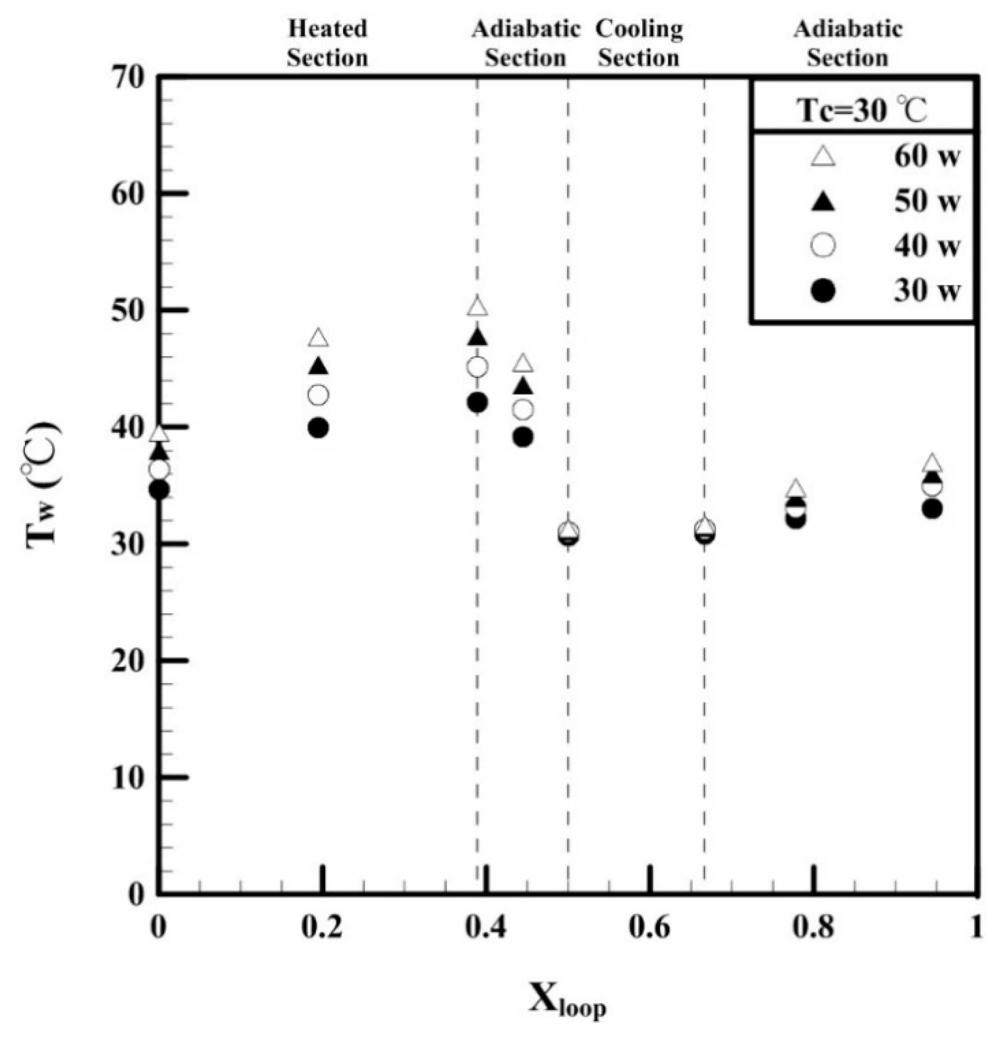
Due to space limitations of this article, only the experimental results for AR = 6 were discussed. The heat flow phenomena for ARs of 4.5 and 3.5 were similar to those for AR = 6 and were not discussed in this paper. Figure 3 shows the distribution of the steady-state wall temperature of the thermosyphon loop at different heating powers and with a cold wall temperature of 30 °C and a circulating water flow rate of 35 mL/s. The dotted lines partition the figure into four blocks, and the point with a dimensionless distance Xloop of 0 was set at the lower-left corner of the loop system (Figure 2a). The Xloop range of 0–0.43 corresponds to the heating section, the range of 0.43–0.5 corresponds to the adiabatic section between the outlet of the heating section and the inlet of the cooling section, the range of 0.5–0.61 corresponds to the cooling section, the range of 0.61–1 corresponds to the adiabatic section after the cooling section, and Xloop of 1 indicates the return to the starting point of the loop (i.e., the starting point of the heating section).
The variation of the wall temperature Tw of the thermosyphon shows that after entering the heating section, the wall temperature of the loop began to increase linearly and reached the highest temperature at the end of the flow passage. After entering the adiabatic section, the temperature decreased considerably. After entering the cooling section, the wall temperature quickly decreased to the set cold wall temperature. The results confirm that the cold wall temperature met the set isothermal state and that the temperature increased after exiting the cooling section.
Next, the influence of different heating wattages on the temperature distribution was analyzed. The results show that the higher the wattage was, the higher the heating wall temperature iswas. In addition, the slope of the temperature variation increased, which reflects the boundary condition of the constant heat flux. In the adiabatic zone between the outlet of the heating section and the inlet of the cooling section, the wall temperature was affected by the low temperature of the cooling section due to the axial heat transfer of the tube wall. Therefore, the temperature decreased considerably after entering the adiabatic section. In the cooling section, the cooling wall temperature was not significantly affected by the wattage, indicating the isothermal condition of the cooling section. In the adiabatic zone between the outlet of the cooling section and the inlet of the heating section, the wall temperature was affected again by the axial heat transfer of the tube wall. The temperature of the cooling section was affected by the high temperature of the heating section, and the temperature increased.
Figure 4 shows the distribution of the maximum wall temperature Tw,max under the specified hot water intake mode (i.e., the cold end circulating water flow rate of 35 mL/s). The results show that at AR = 3.5, as the heating power increased, the maximum wall temperature increased linearly from 42.1 °C (30 W) to 50.3 °C (60 W). The maximum wall temperature decreased nonlinearly with increasing AR. With AR = 6, the minimum temperatures were 39.6 °C (30 W) and 46.2 °C (60 W).
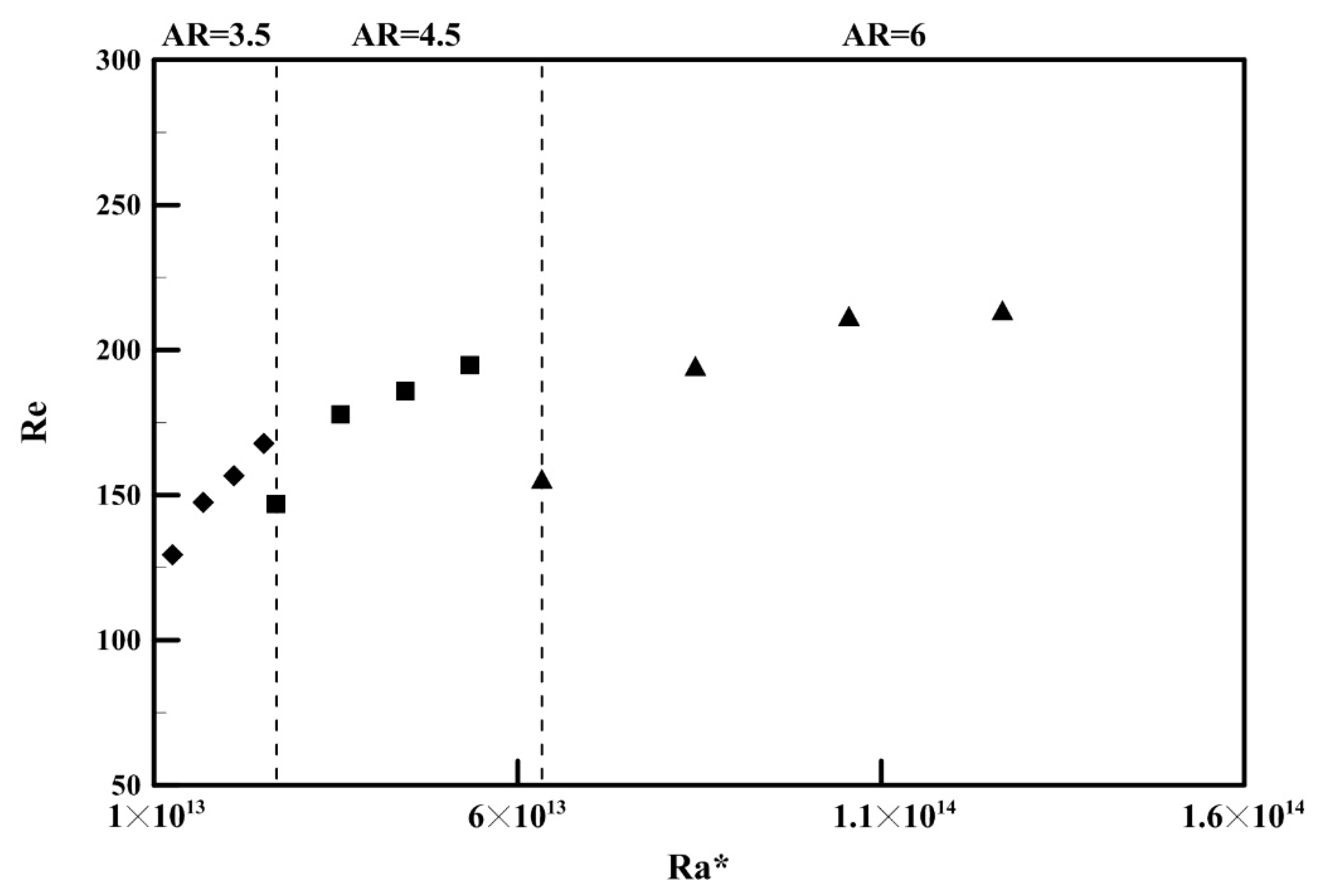
Figure 5 shows the relationship between Re and Ra*. With the same heating power, Ra* increased with the increase of aspect ratio. Within the range of parameter values in this study, Re ranged from 129 to 213, indicating a laminar flow pattern. When AR = 6, Re increased with increasing Ra*, but the upward trend became moderate in the high Ra* range. When AR = 3.5, Re also increased with increasing Ra*, but both the amplitude and the slope of the increase were larger than those with AR = 6.
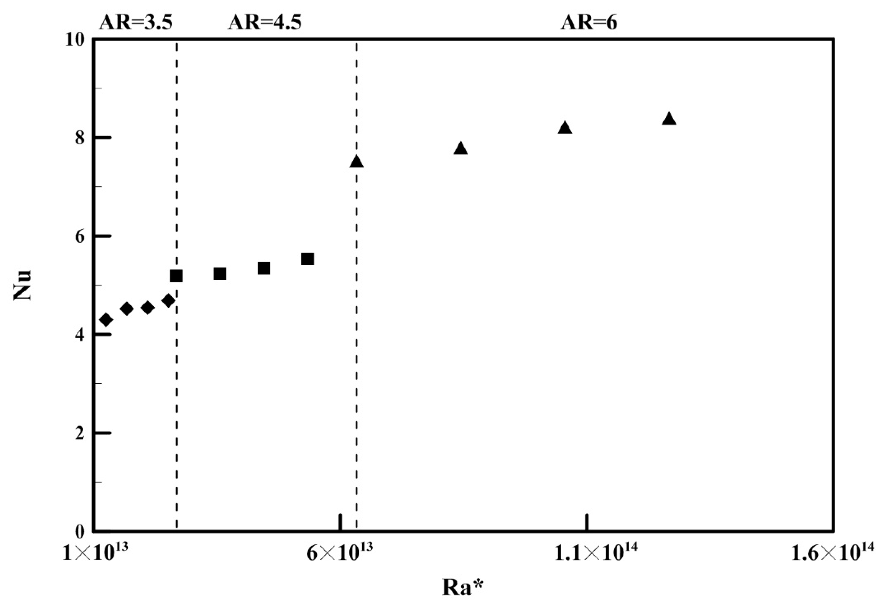
Figure 6 shows the relationship between the average Nu and Ra* in the heating section. Within the range of parameter values in this study, Nu was between 4.3 and 8.4. With a fixed AR, as Ra* increased, the variation in the amplitude of Nu was small. When AR = 3.5, as Ra* increased, Nu increased slightly. Nu increased with increasing AR, indicating that the AR affected the heat transfer performance of the rectangular thermosyphon, that is, with the same heating power, a higher AR corresponded to a better heat transfer capability. Figure 5 and Figure 6 show that as the AR increased, the potential difference ΔZ of the heating section and cooling section also increased, thereby increasing the fluid flow rate and the heat transfer efficiency in the tube. This can be used as a reference for incorporating the studied thermosyphons into building design. When the rectangular thermosyphon inside the metal curtain wall is used to obtain the solar heated water, the opaque part of the metal curtain wall can be raised to make the thermosyphon have a high AR to enhance the heat transfer efficiency.
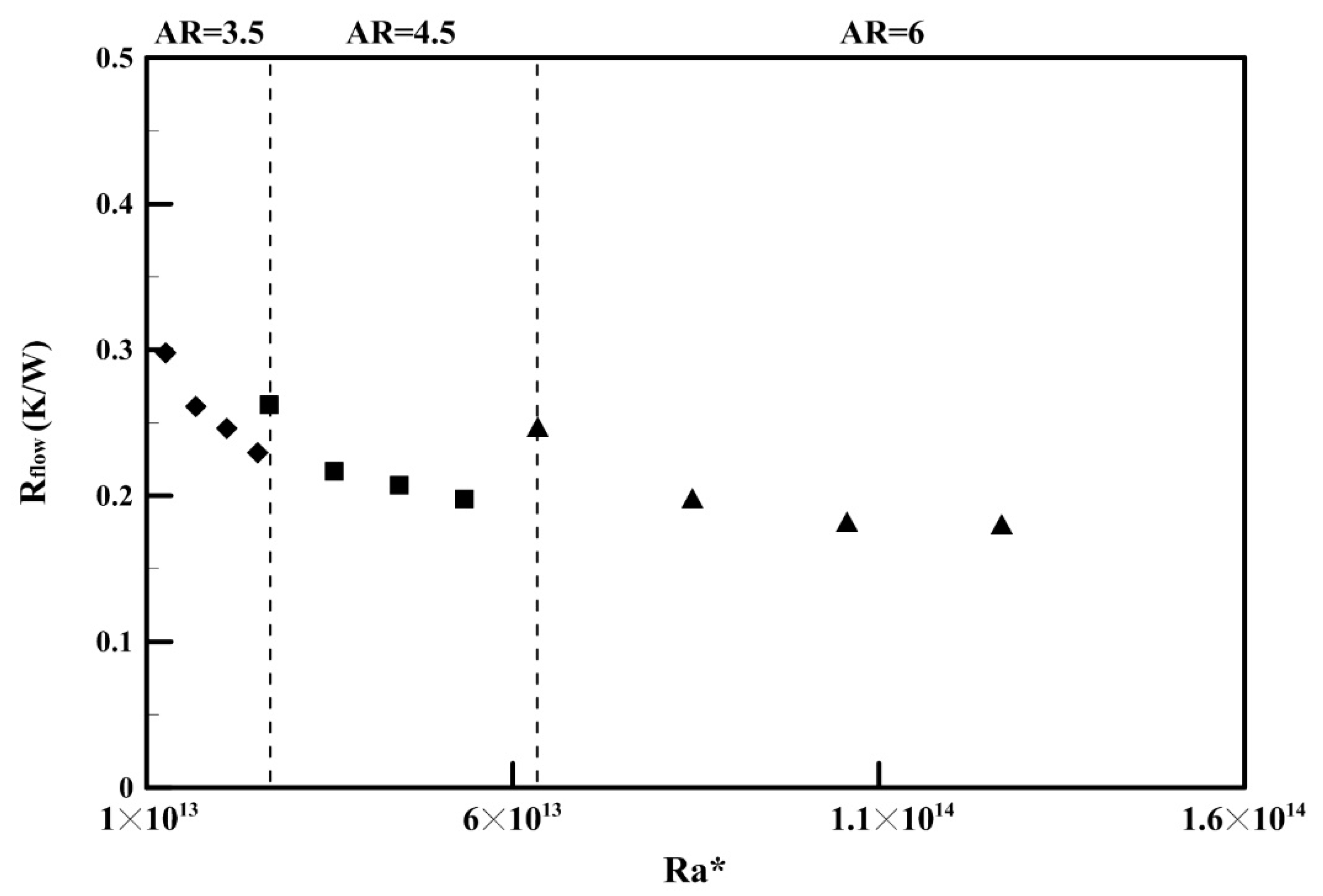
Figure 7 shows the relationship between the thermal resistance of the working fluid flow () and Ra* of the heating section. The higher Ra* was, the smaller was, that is, a higher heating power resulted in greater thermal buoyancy, thereby increasing the flow rate and decreasing . Within the range of parameter values in this study, was between 0.18 and 0.29 K/W.
4. Conclusions
The main purpose of this study was to investigate the effects of different geometric aspect ratios and the heating wattage on the thermal capacity of a rectangular thermosyphon loop with an inner diameter of 11 mm. Based on the experimental results, the following conclusions can be summarized:
- It is feasible to install a rectangular thermosyphon inside a metal curtain wall to obtain solar heated water.
- When the AR increased, the maximum wall temperature decreased nonlinearly. The lowest temperature can be reduced to 39.6 °C and 46.2 °C at 30 W and 60 W, respectively, with AR = 6.
- Within the range of parameter values in this study, Nu was between 4.3 and 8.4. The higher the AR was, the higher Nu was, indicating that the AR can affect the heat transfer efficiency of the rectangular thermosyphon.
- When the rectangular thermosyphon is used inside the metal curtain wall to obtain a solar heat gain, the opaque part of the metal curtain wall can be raised to give the thermosyphon a higher AR to enhance the heat transfer efficiency.
- The larger Ra* was, the lower the thermal resistance of the working fluid flow was, that is, a greater heating power or larger AR resulted in greater thermal buoyancy, thereby causing the flow to increase and the thermal resistance of the working fluid flow to decrease.
The results are limited to the chosen specific aspect ratios (6, 4.5, and 3.5). To respond to the design diversity of balcony exterior walls or curtain walls via the loop geometry configurations, thermosyphons with different aspect ratios could be tested. Although a computational modeling was not the focus of this study, it is worthy of future consideration.
Author Contributions
C.-M.L. and C.S.H. designed the study; C.-W.Y. and C.S.H. performed the experiments; C.-W.Y., and C.S.H. analyzed the data; C.T.T. and C.-M.L. wrote the manuscript.
Funding
This research received no external funding
Conflicts of Interest
The authors declare no conflict of interest.
References
- Esen, M.; Esen, H. Experimental investigation of a two-phase closed thermosyphon solar water heater. Sol. Energy 2005, 79, 459–468. [Google Scholar] [CrossRef]
- Buschmann, M.H. Nanofluids in thermosyphons and heat pipes: Overview of recent experiments and modelling approaches. Int. J. Therm. Sci. 2013, 72, 1–17. [Google Scholar] [CrossRef]
- Ho, C.J.; Chen, Y.Z.; Tu, F.-J.; Lai, C.-M. Thermal performance of water-based suspensions of phase change nanocapsules in a natural circulation loop with a mini-channel heat sink and heat source. Appl. Therm. Eng. 2014, 64, 376–384. [Google Scholar] [CrossRef]
- Ismail, K.A.R.; Abogderah, M.M. Performance of a Heat Pipe Solar Collector. J. Sol. Energy Eng. 1998, 120, 51–59. [Google Scholar] [CrossRef]
- Mathioulakis, E.; Belessiotis, V. A new heat-pipe type solar domestic hot water system. Sol. Energy 2002, 72, 13–20. [Google Scholar] [CrossRef]
- Misale, M.; Garibaldi, P.; Tarozzi, L.; Barozzi, G.S. Influence of thermal boundary conditions on the dynamic behaviour of a rectangular single-phase natural circulation loop. Int. J. Heat Fluid Flow 2011, 32, 413–423. [Google Scholar] [CrossRef]
- Lai, C.-M.; Chen, R.-H.; Huang, C.S. Development and thermal performance of a wall heat collection prototype. Build. Environ. 2012, 57, 156–164. [Google Scholar] [CrossRef]
- Desrayaud, G.; Fichera, A.; Lauriat, G. Two-dimensional numerical analysis of a rectangular closed-loop thermosiphon. Appl. Therm. Eng. 2013, 50, 187–196. [Google Scholar] [CrossRef]
- Huminic, G.; Huminic, A. Numerical study on heat transfer characteristics of thermosyphon heat pipes using nanofluids. Energy Convers. Manag. 2013, 76, 393–399. [Google Scholar] [CrossRef]
- Martinopoulos, G.; Ikonomopoulos, A.; Tsilingiridis, G. Initial evaluation of a phase change solar collector for desalination applications. Desalination 2016, 399, 165–170. [Google Scholar] [CrossRef]
- Ho, C.J.; Chiou, S.P.; Hu, C.S. Heat transfer characteristics of a rectangular natural circulation loop containing water near its density extreme. Int. J. Heat Mass Transf. 1997, 40, 3553–3558. [Google Scholar] [CrossRef]
- Vijayan, P.K.; Sharma, M.; Saha, D. Steady state and stability characteristics of single-phase natural circulation in a rectangular loop with different heater and cooler orientations. Exp. Therm. Fluid Sci. 2007, 31, 925–945. [Google Scholar] [CrossRef]
- Misale, M.; Garibaldi, P.; Passos, J.C.; de Bitencourt, G.G. Experiments in a single-phase natural circulation mini-loop. Exp. Therm. Fluid Sci. 2007, 31, 1111–1120. [Google Scholar] [CrossRef]
- Swapnalee, B.T.; Vijayan, P.K. A generalized flow equation for single phase natural circulation loops obeying multiple friction laws. Int. J. Heat Mass Transf. 2011, 54, 2618–2629. [Google Scholar] [CrossRef]
- Thomas, S.; Sobhan, C.B. Stability and transient performance of vertical heater vertical cooler natural circulation loops with metal oxide nanoparticle suspensions. Heat Transf. Eng. 2018, 39, 861–873. [Google Scholar] [CrossRef]
- Huang, C.S.; Yu, C.-W.; Chen, R.H.; Tzeng, C.-T.; Lai, C.-M. Experimental observation of natural convection heat transfer performance of a rectangular thermosyphon. Energies 2019, 12, 1702. [Google Scholar] [CrossRef]
Figure 1.
Scenario and test cell illustration.

Figure 2.
Experimental test cell and geometric parameters.

Figure 3.
Steady-state temperature distribution of the wall of the loop with different heating powers.
Figure 3.
Steady-state temperature distribution of the wall of the loop with different heating powers.

Figure 4.
Distribution of the maximum wall temperature.

Figure 5.
Relationship between the Reynolds number (Re) and the modified Rayleigh number (Ra*).

Figure 6.
Relationship between the average Nusselt number (Nu) and the modified Rayleigh number (Ra*) of the heating section.
Figure 6.
Relationship between the average Nusselt number (Nu) and the modified Rayleigh number (Ra*) of the heating section.

Figure 7.
Relationship between the thermal resistance of the working fluid flow () and Ra*.

© 2019 by the authors. Licensee MDPI, Basel, Switzerland. This article is an open access article distributed under the terms and conditions of the Creative Commons Attribution (CC BY) license (http://creativecommons.org/licenses/by/4.0/).
Share and Cite
MDPI and ACS Style
Yu, C.-W.; Huang, C.S.; Tzeng, C.T.; Lai, C.-M. Effects of the Aspect Ratio of a Rectangular Thermosyphon on Its Thermal Performance. Energies 2019, 12, 4014. https://0-doi-org.brum.beds.ac.uk/10.3390/en12204014
AMA Style
Yu C-W, Huang CS, Tzeng CT, Lai C-M. Effects of the Aspect Ratio of a Rectangular Thermosyphon on Its Thermal Performance. Energies. 2019; 12(20):4014. https://0-doi-org.brum.beds.ac.uk/10.3390/en12204014
Chicago/Turabian StyleYu, Chia-Wang, C. S. Huang, C. T. Tzeng, and Chi-Ming Lai. 2019. "Effects of the Aspect Ratio of a Rectangular Thermosyphon on Its Thermal Performance" Energies 12, no. 20: 4014. https://0-doi-org.brum.beds.ac.uk/10.3390/en12204014
Note that from the first issue of 2016, this journal uses article numbers instead of page numbers. See further details here.