A Doubly-Fed Induction Generator Adaptive Control Strategy and Coordination Technology Compatible with Feeder Automation

College of Electrical Engineering, Guizhou University, Guiyang 550025, China
*
Author to whom correspondence should be addressed.
Energies 2019, 12(23), 4463; https://0-doi-org.brum.beds.ac.uk/10.3390/en12234463
Submission received: 9 October 2019
/
Revised: 19 November 2019
/
Accepted: 21 November 2019
/
Published: 22 November 2019
(This article belongs to the Special Issue Application of Power Electronics Converters in Smart Grids and Renewable Energy Systems)
Abstract
:The extensive connection of distributed generation (DG) with the distribution network (DN) is one of the core features of a smart grid, but in case of a large number, it may result in problems concerning the DN-DG compatibility during fault isolation and service restoration, for which no efficient and economic solutions have been developed. This paper proposes a doubly-fed induction generator (DFIG) adaptive control strategy (ACS) and a coordination technology to be compatible with the typical feeder automation (FA) protection logics in the ring distribution system. First of all, an ACS simulating the inertia/damping characteristics and excitation principles of synchronous generators is developed to achieve seamless switching between DFIG grid-connection/island modes, and make distant synchronization possible. Next, a technology coordinating the DFIG islands controlled by ACS and the remote tie-switches based on local inspection of synchronization conditions for closing is developed to achieve the safety grid-connection of DFIG islands in the absence of DN-DG communication. At the last, a detailed simulation scenario with a ring DN accessed by five DFIGs is used to validate the effectiveness of ACS and coordination technology compatible with FA in various faults scenes.
1. Introduction
With more distributed generations (DGs) based on renewable energies integrating to the distribution network (DN), traditional DNs are evolving into active ones with more prominent DN-DG contradictions. Overall, the incompatibility and mutual repulsion between the DN and the DG have hindered the upgrading of active DN to smart DN [1,2,3]. Traditional DNs are challenged seriously by the compatibility between DG and DN in terms of topology structure, operating standards, control modes and protection configuration [1,4]. From the perspective of protection, traditional DN is generally a radiating structure from substations to users, and support fast fault isolation and service restoration based on equipment such as relays, circuit breakers, reclosing devices, sectionalizing switches and fuses [5,6,7]. Nevertheless, the application of DGs has changed the topology structure of traditional radical DN, which may lead to serious problems in the normal operation of protections to traditional DN, including false tripping of feeders, protection inaction, raised or reduced failure level, unintentional islanding, asynchronous closing and failed automatic reclosing [8,9]. Therefore, the reliability of traditional distribution systems are compromised by the installation of DGs as it results in failure of protection coordination. In the meantime, the safety of DGs is also challenged.
In recent years, researchers and institutions around the work have proposed various protection strategies and specific control technologies for active DNs, aiming to fast isolate the failures in the protection system at the grid side, and guarantee the safe operation of DGs at the DG side, while power authorities and international power organizations have formulated protection standards and specifications for DNs involving DGs to enhance the reliability of the DN [10,11]. Presently, the mainstream engineering DN-side protection is fast and non-selective connection of all DGs in case of any failure in the DN in any form, so that the existing protection will not be negatively affected [12]. Where an islanding status is detected by an existing DG, its internal control system will, in general cases, activate the anti-islanding protection mechanism to achieve disconnection and shutdown of DGs quickly [10,13], while DGs with fault rid-through capacity can be removed from the grid after a delay of a limited period in any failure [8]. For doubly-fed induction generator (DFIG), it will start crowbar protection immediately under fault scenario [7]. Obviously, the protection strategies at the DN and DG sides are comparatively conservative and weaken the advantage of DGs in improving power supply reliability. Furthermore, the disconnection and shutdown of DGs may affect stability of the grid, disadvantage service restoration, and result in additional maintenance costs [12,14].
Therefore, some new strategies are put forward successively and can be categorized generally into 2 types: ① DG improvements and reserved DG-side protection strategies; ② Improvements in DG-side protections and reserved DG strategies. In the first solution, DG output is limited and DG connecting position is optimized to avoid any impact on the DN protection [15,16]. Limiting DG output is easy to implement, but deviates from the initial intention of sufficient and flexible utilization of DG energies. Optimizing DG connecting position can reduce the power loss of the DN and improve voltage distribution. However, the best DG connecting position is subject to natural and geographical environments [17]. Therefore, optimizing the DG connecting position is not a preferred strategy in an established active DN. The second solution achieves adaptation to the large number of DGs by improving DG-side protection. It falls into six forms: voltage-based protection, improved current protection, differential protection, distance protection, adaptive protection and fault current compensation [2]. Those improved protection strategies have significantly improved the reliability of protective device whenever the DGs are in grid-connected or island modes. Essentially, they are developed against problems in the active DNs, such as fault identification, location and isolation, and fail to take into consideration the safe operation of DGs when the topology structure of the DN is changing dynamically. In particular, the specific strategies DG follow to withstanding the abnormal DN-side interruptions and service restoration in the continuous process from sudden tripping of circuit breakers to the closing of tie-switches are seldom referred. Reference [18] suggests closing the tie-switch 15 ms before circuit breakers trip to isolate the fault segments, to make sure DGs can maintain grid-connected power generation during and after faults, but, closing the tie-switch at the presence of faults may result in overvoltage or overcurrent, and the coordination between protection devices for actions in a ms places high requirements on the communication system and the circuit breakers. Reference [19] proposed a strategy of output matching of DGs through the local controllable load bank when they are disconnected, in order to maintain their status before the fault without immediate stopping, and realize fast reconnection by reclosing as the power is recovered. Instead of changing the structures and settings of existing DN-side protection system, this strategy further expands the application level of DGs, and directly reduces the costs of DG stopping and restart. However, it is a conservative disconnection strategy essentially that the DGs fail to continuously supply powers to local loads during a fault, and an additional controllable load bank is required.
It should be noted that in case of a fault, active DNs have achieved a lot in fault isolation, but the compatibility between DGs and DN-side protection devices is still a challenge in a true sense. The existing active DNs lack experience in technology docking and integration in terms of DN-DG coordination, and the strategies adopted are more conservative, while standards and operation guides concerning the deployments of DGs to the DN are based on the technical level at present, which will surely be removed through the technical route and utmost goals of smart DN to achieve the real integration of DGs and the DN.
Therefore, this paper gives a solution and the contributions of this paper which are emphasized in the following points:
- ①
- This paper proposes a doubly-fed induction generator (DFIG) adaptive control strategy (ACS) which possesses the capabilities of dual-mode operation, restraining sudden changes of rotor current and distant synchronization, making seamless switching between grid-connection and island can be achieved and making distant synchronization possible without switching control strategies.
- ②
- This paper proposes a coordination technology which combines the DFIG islanding controlled by ACS with remote tie-switches based on local inspection of synchronization conditions for closing to achieve the safety grid-connection of DFIG islands in absence of communication between DFIG and DN.
- ③
- The ACS and coordination technology allows DFIG (not limited to a single wind turbine) continuously supply power to partial local loads during the dynamic process of feeder automation (FA) fault isolation and power recovery without shutdown and restart of DFIG, realizing the compatibility between DFIG and feeder automation (FA).
This paper consists of Section 2, which summarizes the active distribution system studied herein, and analyzes the contradictions between existing FA protection logics and DFIG, Section 3, which specifies the solution for DN-DFIG compatibility, Section 4, which describes and analyzes the proposed DFIG ACS and coordination technology in details, and Section 5, which exhibits the simulation results in various scenes and some discussions are given. Conclusions can be found in Section 6.
2. Contradictions in Active Distribution Network
2.1. System under Study
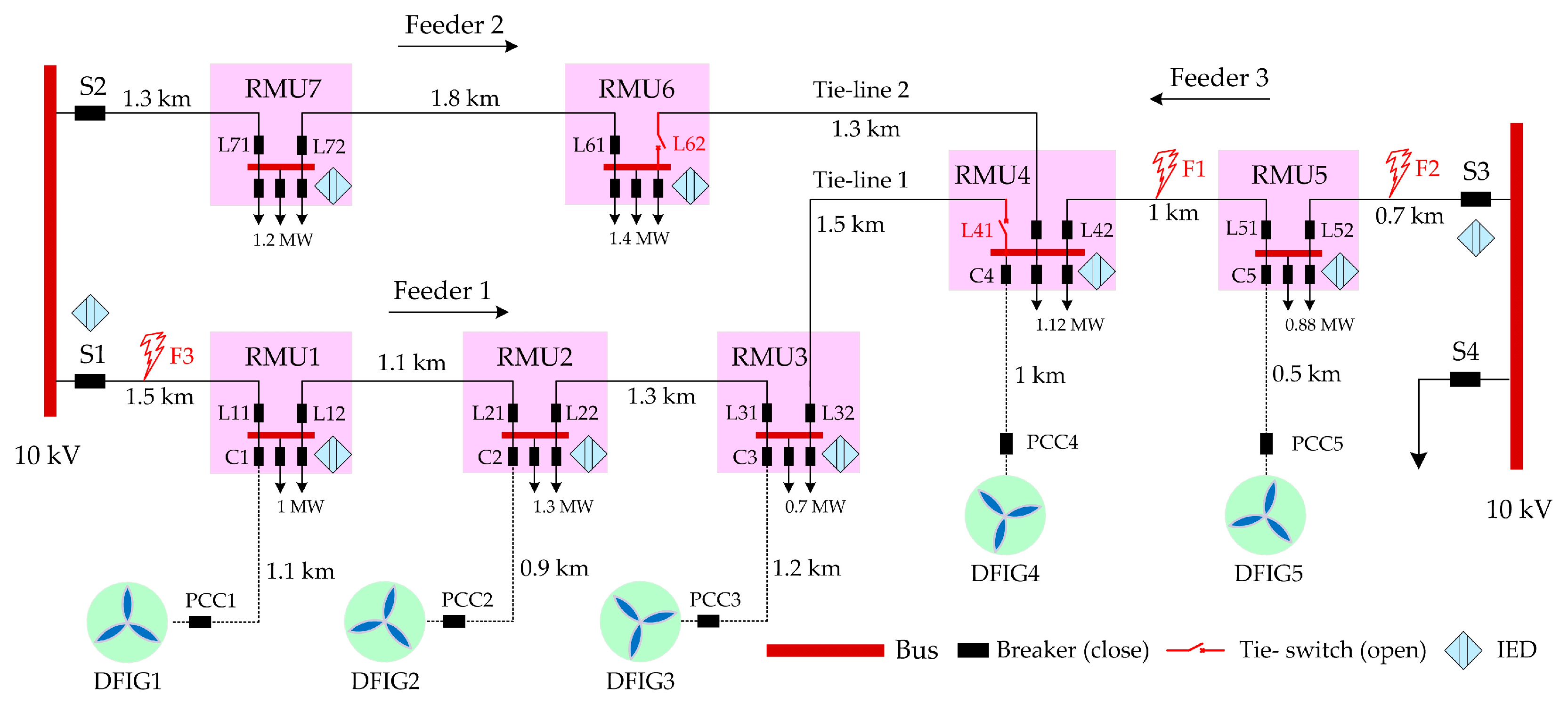
Modern DNs require flexible and reliable operations based on closed-loop design and open-loop operation [20]. Accordingly, an active DN as shown in Figure 1 is selected, in which, the primary system adopts a ring network structure with S1, S2, S3 and S4 at the outlet switches by both sides of the substation.
Three feeders are led out via S1, S2 and S3, and interconnected through the ring main unit (RMU). All inlet and outlet switches of the RMU are circuit breakers, while the tie-switches L41 and L62 are normally opened. The tie-line 1 connects with feeders 1 and 3, and the tie-line 2 connects with the feeders 2 and 3. All feeders are underground cables. Five DFIGs connect to the DN through RMUs at different positions. The secondary system is configured as a typical intelligent distributed FA independent from the overall information from the master stations or slave stations, and exchanges fault information by peer-to-peer communication between intelligent electronic devices (IEDs), to realize fast isolation of feeder faults and service restoration [21,22,23]. The communication network supports optical fiber Ethernet structures according to IEC 61850, while the IEDs at the substations and the RMUs communicate with each other through the core switchers. The generic object oriented substation event (GOOSE), a fast message communication mechanism, is adopted for communications between IEDs [20].
2.2. FA Protection Logics
In Figure 1, permanent faults of cable feeders are designated as F1, F2 and F3. In case of a fault in the DN, FA controls the circuit breakers at both sides of the fault feeder through GOOSE message communication mechanism to isolate faults by tripping, after which, a GOOSE message of fault isolation successful (FIS) will be sent to the corresponding tie-switch for closing. For the relations between feeders and tie-switches, feeder 1 corresponds to the tie-switch L41, and feeder 3 to L62. Therefore, when a fault takes place on feeders 1 or 3, the tie-switches L41 or L63 is closed after fault isolation by FA accordingly.
2.3. Contradictions between FA and DFIG
Traditionally, DFIG is controlled by PQ (active and reactive power control) [24] for grid-connection and VF (constant-voltage constant-frequency control) for islanding [25]. In case of islanding a number of DFIGs, master-slave, peer-to-peer or hierarchical control is required [26]. Therefore, DFIG works on continuous grid-connection or pure islanding mode at present without switching between the two. There are few DFIGs capable of operating under the two modes, or supporting their seamless switching. As different modes demand different control strategies and operation rules, DFIG requires island detection technology to achieve switching between grid-connection and island modes. There are three island detection technologies: communication-based, active and passive [10], and the establishment of communication between DFIG and DN results in additional costs and higher complexity of DFIG penetration. Operated by different companies, the DFIG is not connected to the DN through secondary cables in real cases, while the active and passive island detection technologies are not reliable enough and a certain period of time elapses before an island is detected [10]. Furthermore, the DFIG is located comparatively remote from the DN (1-2 km in general cases), and the tie-switches are flexibly positioned, requiring a distant synchronous grid-connected process for DFIG islands in grid-connection through tie-switches, which makes this new mode essentially different from the traditional local synchronous grid-connection technology of DFIG. Again, the existing GOOSE fast communication mechanism, in essence, works by repeated transmission of state messages (e.g., circuit breaker tripping or closing) and fails to achieve the real-time transmission of remote sinusoidal quantity, while the SV message is not an economic and reliable solution for the DN.
For those reasons, when the DFIG is connected to the DN (Figure 1), 2 contradictions are expected between FA and DFIG to make sure the DFIG serves partial local loads without interruption, and safely close in coordination with the tie-switches. Contradiction 1: a series of switch state messages in the discretion of FA cannot be timely “notified” to DFIG, rendering the latter’s failure to adapt to the topology changes of the grid; without supports to dual-mode operation, DFIG cannot adjust its control modes timely for the purpose of seamless switching between the grid-connection and islanding. Contradiction 2: the information channel and message specifications of the DN provide no supports to the distant synchronization function to transform the DFIG status from off-grid to grid-connection. The two contradictions account for the incompatibility and mutual repulsion between existing FA technologies and DFIGs, and hinder the upgrading from active DN to smart DN.
3. Solution for DN-DFIG Compatibility
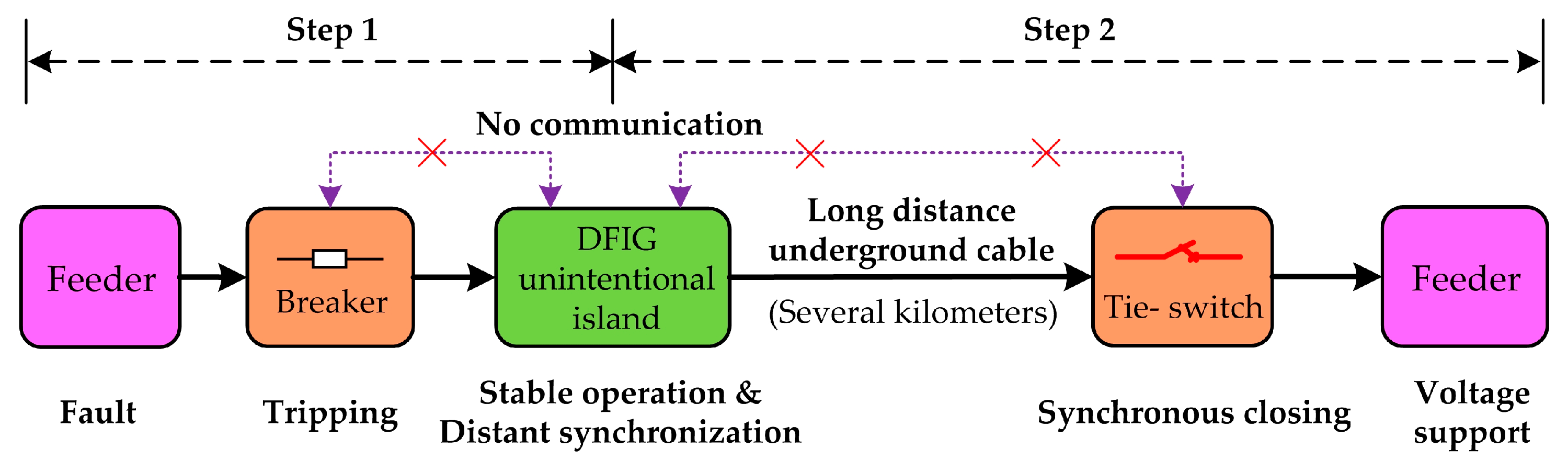
The active distribution network system studied in this paper is 10 kv level, and DFIG is megawatt class (1.5 MW). It is assumed that FA can instantly isolate any fault. In addition, there is no any communication between DFIG and DN, and no support of energy storage widely used in microgrid [27,28]. With remarkable kinetic energy stored in its wind wheels and shafts, the megawatt DFIG can continuously supply power to partial local loads through advanced control strategies in case of an emergency. To sufficiently and flexibly leverage the potential of DFIG for enhanced resilience of the DN where no conditions for DN-DG communication are created, this paper proposes a DN-DG compatibility solution as shown in Figure 2, which contains two steps. Step 1: As the circuit breaker trips for fault isolation, the DFIG switches into the unintentional islanding mode seamlessly and operates stably. At the same time, DFIG islanding actively create distant synchronous conditions at remote tie-switch. Step 2: Remote tie-switch is permitted to close synchronously for the purpose of reconnection of DFIG island and recovering DFIG to the pre-fault status or to a new stable status.
For DFIG, the solution is to realize the continuous and seamless switching amongst unintentional stable operation of islands, distant island synchronization and island grid-connection. Such a process relies on advanced DFIG grid-connection/island dual-mode control strategy and coordination between DFIG and DG-side protection devices. Therefore, an adaptive control strategy and a coordination technology are proposed in the following Section.
4. The Proposed Adaptive Control Strategy and Coordination Technology
4.1. DFIG Adaptive Control Strategy
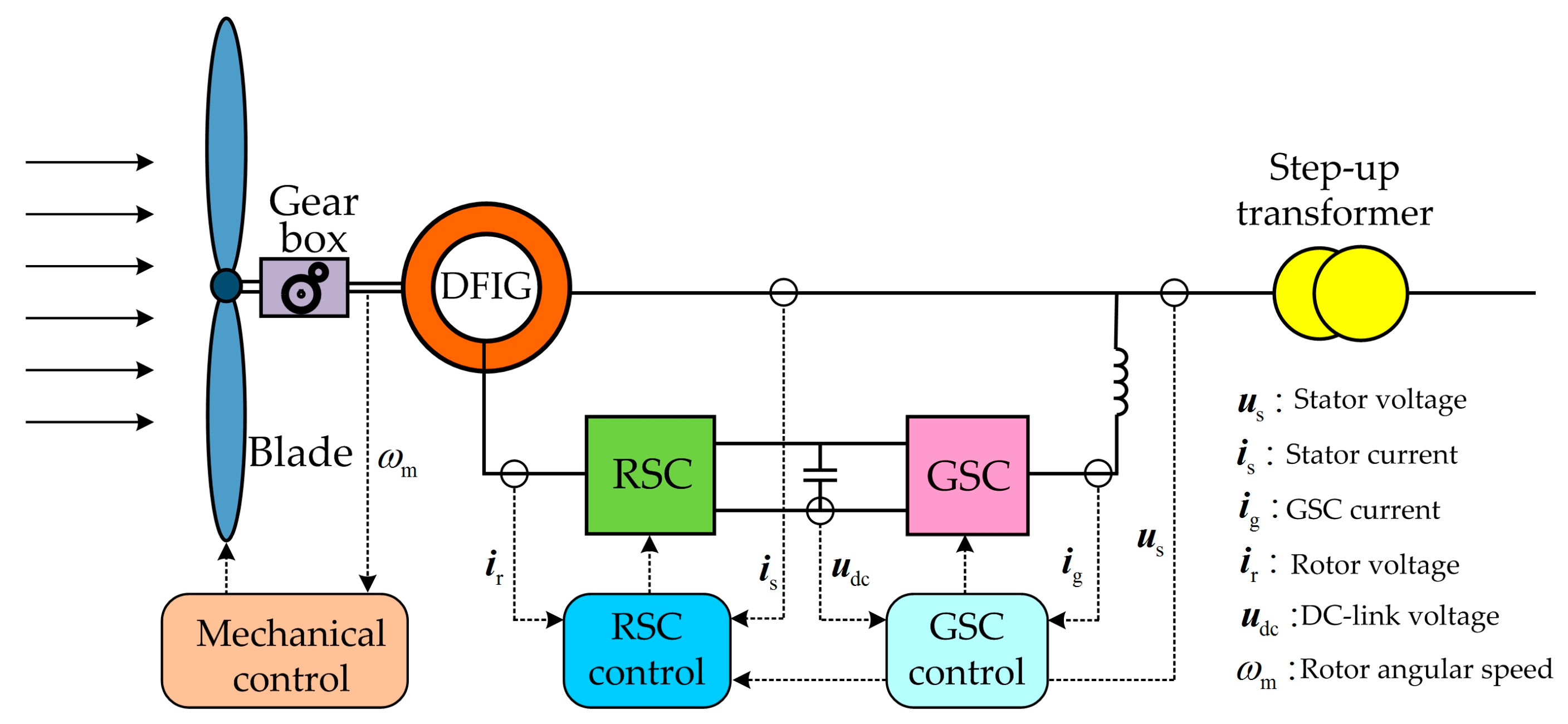
A typical DFIG system is illustrated in Figure 3. The wind wheels transform the wind energy captured into rotary mechanical energy which is delivered to DFIG via the gearbox shafts [29]. The stators of DFIG directly connect to the DN, while the rotators are through the back-to-back converter. The grid-side converter (GSC) is responsible for constant DC bus voltage, while the rotor-side converter (RSC) regulates the excitation voltage of rotors to realize DFIG grid-connection and power generation. This paper adopts GE 1.5 MW DFIG system [30] as an example, which contains mechanical and electrical controls. Mechanical control further divides into speed control, compensation control and torque control, and electric control consists of the GSC-side control and the RSC-side control. The nomenclatures of all variables used in this paper are shown in Table A1 (Appendix A). All quantities are in per unit except for the variables related to phase and special instructions in Section 4. Table A2 (Appendix A) and corresponding Figures shows the variable units in Section 5. The DFIG ACS proposed in this paper aims at RSC-side control and it has three capabilities, including dual-mode operation, restraining sudden changes of rotor current and distant synchronization. The basic control structure of the GE 1.5 MW DFIG [30] for the mechanical part is adopted, while the GSC-side control still follows the typical vector control strategy based on phase-locked loops (PLL) [31]. The maximum power point tracking (MPPT) of the wind turbine [30] is calculated as follows:
where is the reference angular velocity of the wind turbine, and is the actual output electromagnetic power. Therefore, in the MPPT, the speed of the wind turbine depends on the actual output electromagnetic power.
When the rotor follows motor convention and the stator applies generator convention, the space vector model of the DFIG in the stator static reference frame can be expressed as:
where all quantities are in per unit. D is the differential operator (); the electric angular frequency of rotor; and are resistances of stator and rotor, respectively; , and are stator self-inductance, rotor self-inductance and mutual inductance, respectively; and , and are voltage and current space vectors of stator and rotor under stator static reference frame respectively.
The proposed DFIG ACS is shown in Figure 4 and consists of power control, voltage control and current inner loop, of which, the power control simulates the inertia / damping characteristics of the synchronous generator [32]. is inertial link of power control; inertia time constant of power control; proportional coefficient of power control. The electromagnetic power reference is produced by torque control in the mechanical control part. Where the actual power output losses its balance with the reference, ACS will regulate the inner potential angular frequency of the stator through the inertial link and the proportional link, based on which, the inner potential control phase of the stator is obtained through the integral. is the angular frequency of fundamental wave and the rotor’s excitation current phase is obtained by minus the rotor phase . In the meantime, damping negative feedback control is introduced to inhibit the frequency oscillations in the DFIG. The damping power is determined by the difference between the inner potential angular frequency of the stator and the reference angular frequency of the grid after the damping link. is the power control damping coefficient.
The voltage control simulates the excitation principles of the synchronous generator. The reference of rotor’s excitation current amplitude is obtained through a typical PI controller based on the difference of , the reference of stator voltage amplitude, and , the actual stator voltage amplitude. and are respectively the voltage control proportion and integral coefficient.
A three-phase independent control mode is adopted for the current inner loop, in which, “r”(superscript) represents the value in the rotor reference frame. The space vector reference of the rotor excitation currents is defined by the phase and amplitude obtained by power and voltage controls, and converted to abc coordinate to obtain the reference of three-phase rotor excitation currents (, and ), which correspond to the actual excitation currents of rotor (, and ), different between which is based on to obtain the three-phase excitation voltages of the rotor (, and ) through the control. , quasi-proportional resonant controller (QPR), better fits for precision control of sinusoidal signal as compared with traditional PI controllers, and the transfer function can be expressed as [33,34]:
where is the proportional coefficient, the resonance term gain, the resonance term bandwidth (actual value), and the slip angular frequency (actual value). The design of QPR parameters can be found in [33,34].
4.1.1. Grid-connection/island Dual-mode Operation
According to Equation (2) and by neglecting the resistant of stator, the inner potential of stator can be expressed as:
where, , , , and is the synchronous angular frequency. According to ACS control structure (Figure 4) and Equation (5), and by taking the current inner loop with rapid dynamic response as an ideal link, the inner potential of stator es can be further expressed as:
where is the inner potential amplitude of the stator, and , the inner potential phase of the stator. According to formula (6), the difference between and is , and the amplitude reference of rotor’s excitation current is proportional to the inner potential amplitude of the stator. Therefore, the inner potential of stator is subject to the direct control of ACS. When the DFIG is grid-connected, the stator voltage is clamped down by the grid voltage, and the power control will adjust the inner potential of stator based on the grid voltage, and transmit power to the grid. Thus power control plays a leading role, and the voltage control plays an auxiliary role. When the DFIG is suddenly islanded, and supply power to partial loads, the loss of supports from grid voltage will result in the voltage control at the dominating role and the power control automatically adjust the speed of the wind turbine and output energy to serve the island loads under the MPPT in formula (1). By damping negative feedback control and frequency amplitude limitation, the island frequency is controlled within a certain range. Instead of tracking the maximal wind energy, the MPPT under islanding mode guides the wind turbine to adjust its speed based on the loads. The particular case is that multiple DFIGs are suddenly islanded when the slow dynamic response of DFIG mechanical control will lead to the gradually balance between the mechanical energy absorbed by each wind turbine and the loads to jointly supply power for loads. Therefore, ACS can transmit the power captured to the grid during grid-connection mode, and supply power to loads by controlling the voltage of stators in the island mode. Furthermore, when the system switches between grid-connection/island modes, the ACS can directly produce the inner potential phase of the stator by power control to avoid sudden change in the stator’s voltage phase and facilitate the seamless switching between the two modes.
4.1.2. Equivalent Inertia/Damping Characteristics
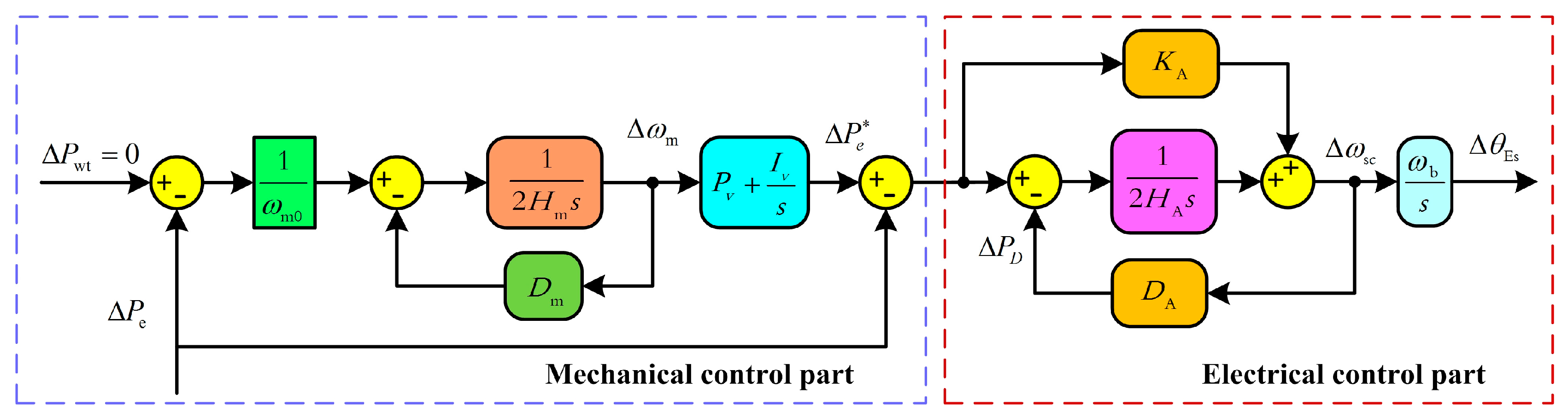
The equivalent inertia/damping characteristics of DFIG take both mechanical control and electrical control into consideration. To facilitate analysis, it is assumed that the stator voltage, the wind speed (actual value) and the pitch angle (actual value) of blades remain constant when the mechanical energy capture by the wind wheel is out of balance with , and the impact of speed on the wind turbine is neglected. By linear processing of the mechanical control of the wind turbine and the electrical control of the ACS, a small signal equivalent model as shown in Figure 5 is obtained. is the stable speed of the wind turbine at a certain operation point, the time constant of the wind turbine’s inherent mechanical inertia, the inherent mechanical damping coefficient of the wind turbine, and the proportional and integral coefficient of the torque control.
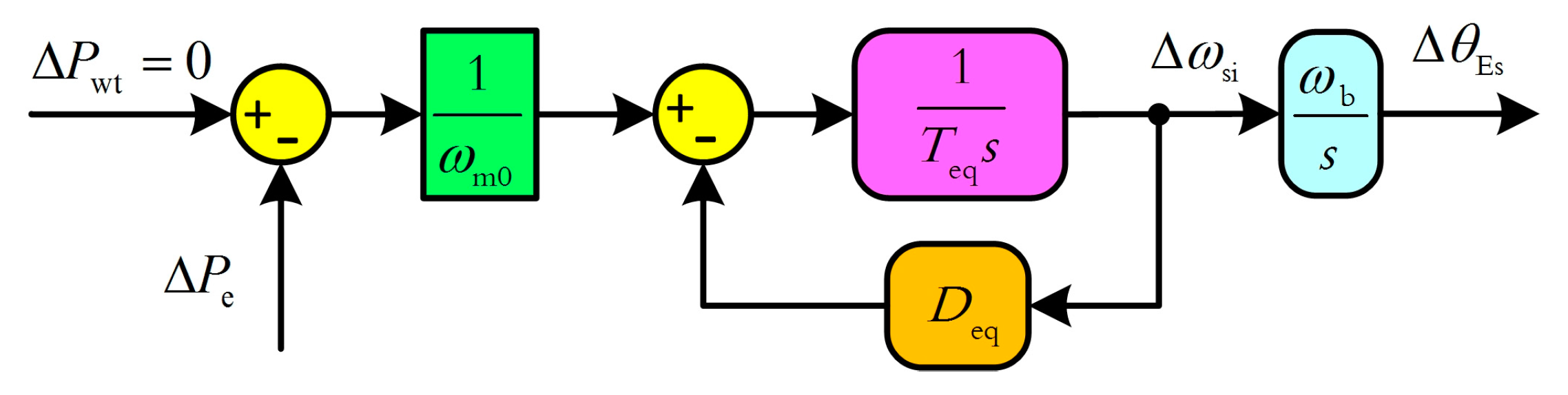
The small signal equivalent model of DFIG in the Figure 5 is properly converted to obtain the equivalent inertia/damping model of DFIG as shown in Figure 6, where, and represent the equivalent inertia and equivalent damping of DFIG under ACS control. Formulas (7) and (8) are the expressions of and respectively.
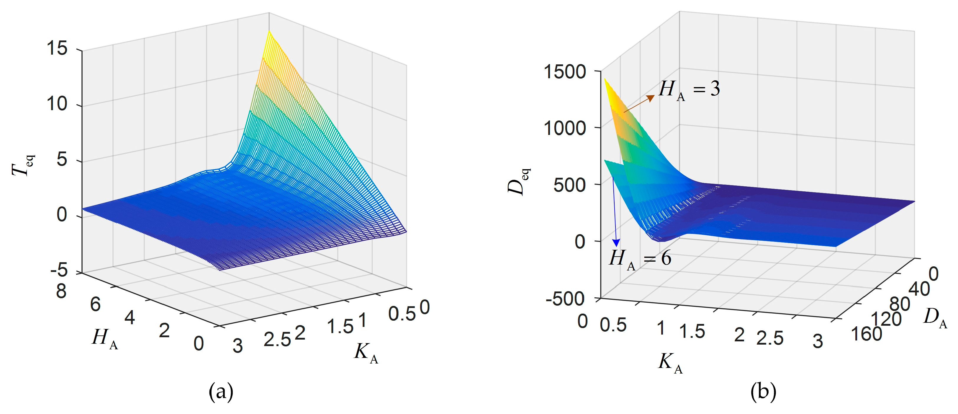
Formulas (7) and (8) reflect the equivalent inertia’s association with the inertia time constant and the proportional coefficient , while the equivalent damping is related with the inertia time constant , the proportional coefficient and the damping coefficient . It is assumed that the wind speed is 15 m/s, then the stable speed , the inherent inertia/damping of the wind turbine are , , and the parameters of the torque control are and [32]. The maximal equivalent inertia of different inertia time constant and proportional coefficient are as shown in Figure 7a. When , the equivalent inertia significantly increases with and when , the increase slows down. Under the same operation conditions, the maximal equivalent damping of different inertia time constant , damping coefficient and proportional coefficient are shown in Figure 7b. Overall, when the proportional coefficient satisfies the relation of , the equivalent damping significantly increases with the coefficient of damping , and a smaller inertia time constant corresponds to a larger equivalent damping. Obviously, ACS can have large equivalent inertia and damping by choosing appropriate parameters. In this paper, the parameters selected are , and .
4.1.3. Features of Current Inner Loop Control
When the wind turbine accidentally enters into the island mode, the loads may be out of proportion to the outputs, resulting in fluctuation of stator’s voltage amplitude and large induction voltage and current at the rotor side. Therefore, the switching between grid-connection/island modes requires proper control of the rotor current to avoid loss of control and damages to the rotor and the RSC. The current inner loop in ACS is designed as rapid dynamic response, and the voltage control is designed as slow dynamic response. In the transient of switching between grid-connection/island, it can be approximately taken as the reference of the rotor excitation current due to voltage control remains the same, and the current inner loop based on QPR can restrain the large current of the rotor to achieve stable and safe control.
4.1.4. Principles of Distant Synchronization
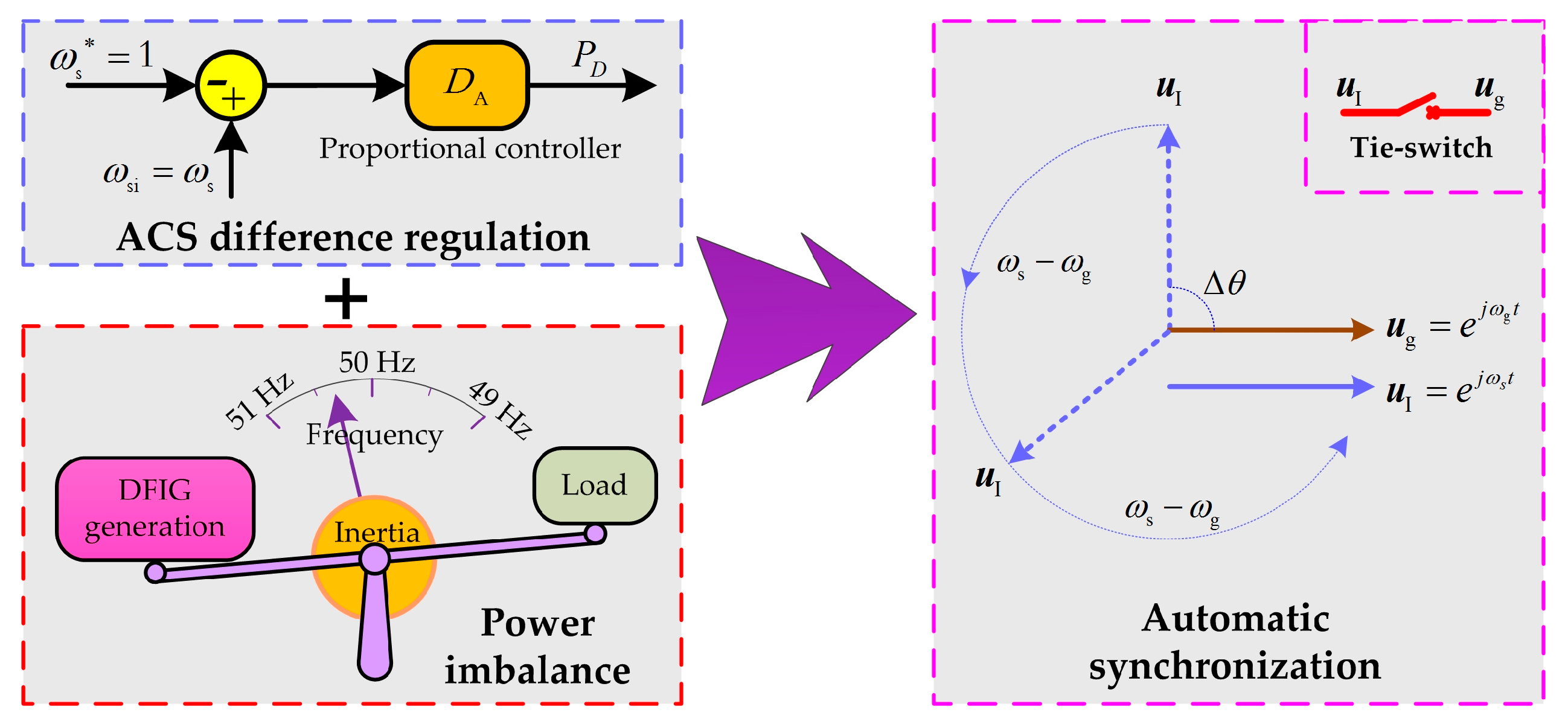
The absence of secondary cable connection between the DFIG and the tie-switch results in the fact that the grid-connection of DFIG islands via remote tie-switches cannot be solved by traditional DFIG local synchronous grid-connection technologies. Tie-switches cannot create conditions for synchronization actively. Instead, it is the DFIG responsible for this. The principles of distant synchronization of DFIG islands as proposed in this paper are shown in Figure 8.
The negative feedback control of damping in the ACS is equivalent to the proportional controller of the stator’s voltage angular frequency . According to the principles of automatic control, proportional control is based on difference regulation, which will lead to inequality between the island’s angular frequency and the grid’s voltage angular frequency ; furthermore, the given the slow dynamic response from the mechanical control of the DFIG, when the DFIG is accidentally islanded, its generation fails to reach a balance with the loads in a short period of time, leading to deviation in the island’s voltage frequency. Henceforth, the difference regulation of ACS to the stator’s voltage angular frequency and the power imbalance will result in relative movement between the DFIG’s island voltage and the grid voltage that as time elapses, the synchronization conditions at any remote tie-switch can be satisfied automatically.
4.2. Coordination Technology
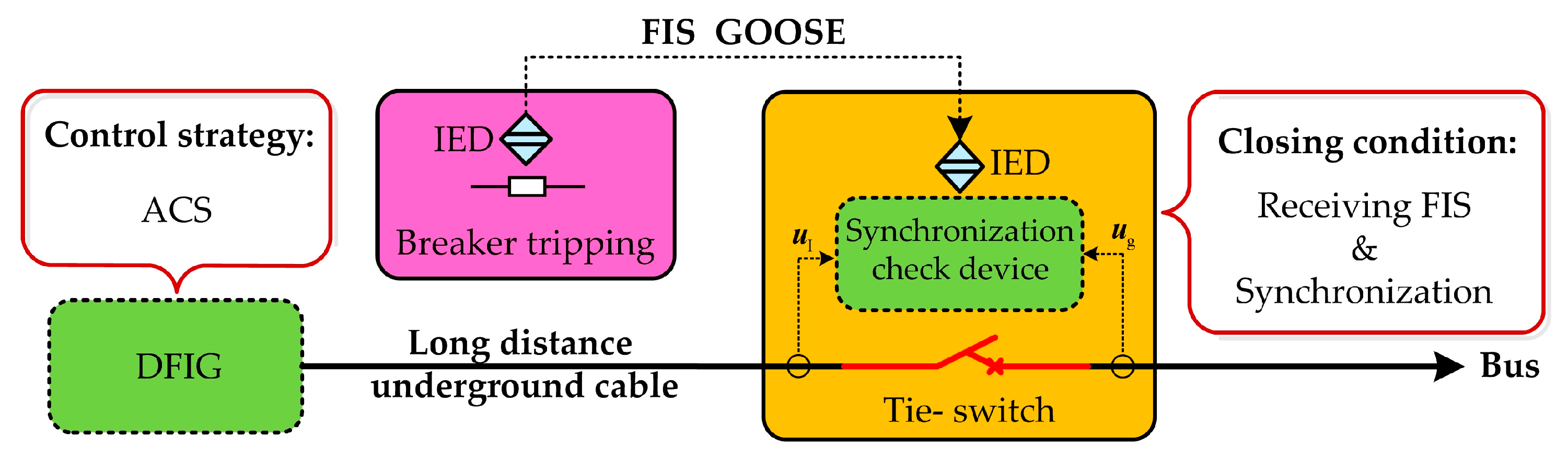
Traditional protection of passive DN focuses on the coordination of protection devices. In the active DN, if the tie-switch still follows the mechanism of closing upon receipt of the GOOSE message of fault isolation successful (FIS), the DIFG island is likely to be non-synchronized connection to grid, resulting in the failure of closing and even the destruction of DFIG and circuit breakers. Therefore, DN-DG coordination is also required in active DN. In this paper, a DN-DG coordination technology is proposed as shown in Figure 9. First is the synchronization check device at the tie-switch whose closing conditions are set as follows: in the process of automatically creating the distant synchronization conditions by the DFIG island under the control of ACS, the tie-switch closes immediately after the receipt of the FIS and detection of synchronization through the check device. As the DFIG controlled by ACS supports grid-connection/island dual-mode operation, DFIG will automatically adapt to the change from island to grid-connection after the tie-switch closes, and recover grid-connected operation. Therefore, in this paper, the technology of coordinating DFIG under the control of ACS with remote tie-switches for local check of synchronization conditions is proposed to realize the secure grid-connection of DFIG islands without an expensive and complex DN-DG communication system.
5. Case Analysis
To validate the effectiveness of the DFIG ACS and coordination technology compatible with FA, the simulation scenario as shown in Figure 1 and detailed models of DFIGs and converters [30,35] are established in MATLAB/Simulink. The selecting of five DFIGs in Figure 1 is to simulate the situation of multiple DGs connected to DN from different locations, the probabilities of multiple DGs unintentional island and multiple DGs reconnecting to grid. For parameters of DFIG, ACS and the DN, please refer to Table A2 (Appendix A). The first test target is the effectiveness of ACS in grid-connection mode, followed by the effectiveness of ACS and coordination technology after the tripping of circuit breakers under FA control in different DN fault scenes.
5.1. Grid-connection Test
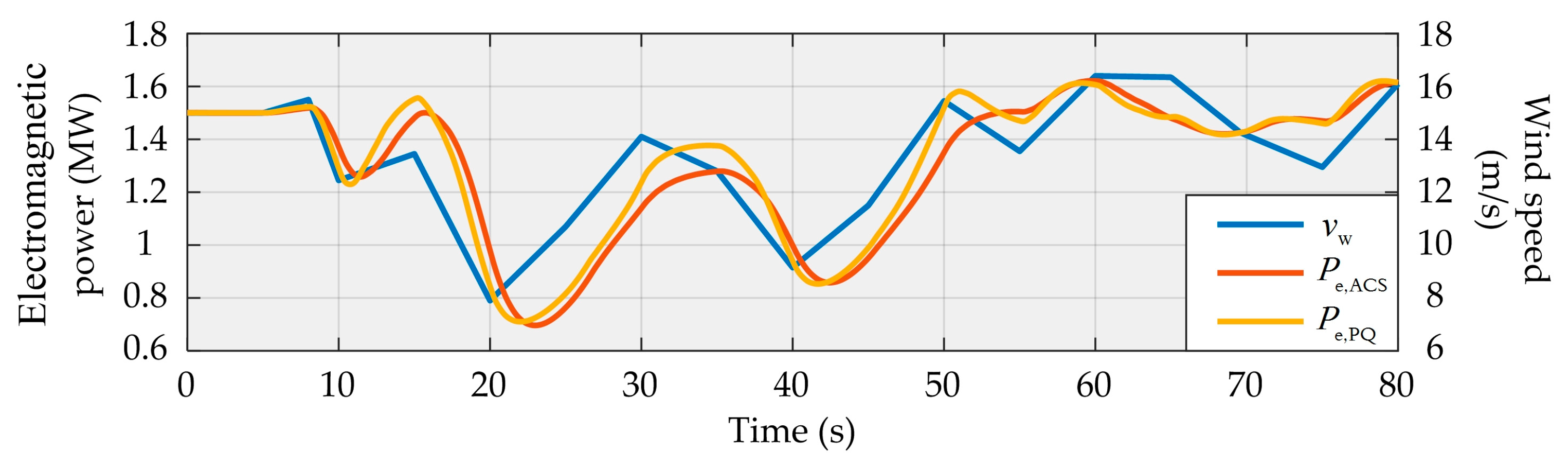
The electromagnetic power waveforms of DFIG under traditional PQ control and ACS control at the same wind speed are shown in Figure 10, in which, the simulation time is 80 s, is set as the typical wind speed, is the electromagnetic power waveform under traditional PQ control strategies, and is the electromagnetic power waveform under the ACS. It is obvious that when the wind speed varies sharply from 10 s to 50 s (7.9–15.45 m/s) in a jagged form, the waveform at can follow up the changes of the wind speed more quickly as compared with which changes more smoothly; when the wind speed changes slightly from 50 to 80 s (13 to 16.5 m/s), there is no huge difference between the waveforms of and . The reason for this phenomenon is that the traditional PQ control does not have a large inertia characteristic, and its dynamic response to electromagnetic power is faster. However, the ACS control proposed in this paper has a large inertia, so its dynamic response to electromagnetic power is slower. In general, both waveforms have experienced the similar trends, and the DFIG under ACS control can track the power of wind turbine achieving effective operation in grid-connected mode.
5.2. Tests under Different Fault Scenes
The DN in Figure 1 includes three permanent fault scenes of cable feeders, and has simulated the adaption and coordination process of different number of DFIGs with the DN at various wind speeds when they are islanded out of schedule. This paper ignores the effects of faults and assumes that the FA can isolate faults instantaneously. It is assumed that the maximal allowable transient frequency of the DN is 51 Hz, and the error between the voltage phases by both sides of the tie-switches is 180°.
Scene 1: Unintentional Island with One DFIG Reconnecting to Passive Feeder
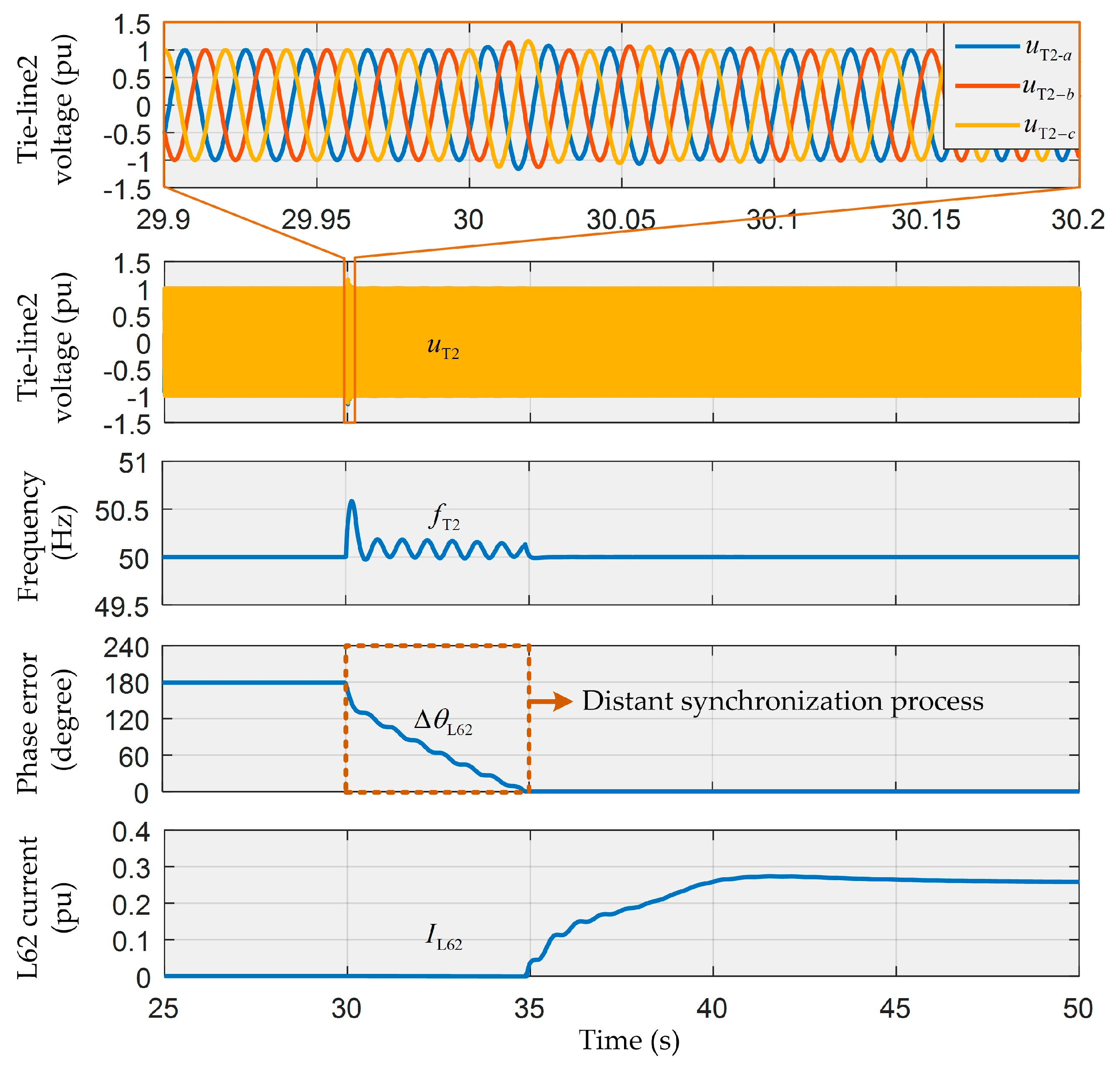
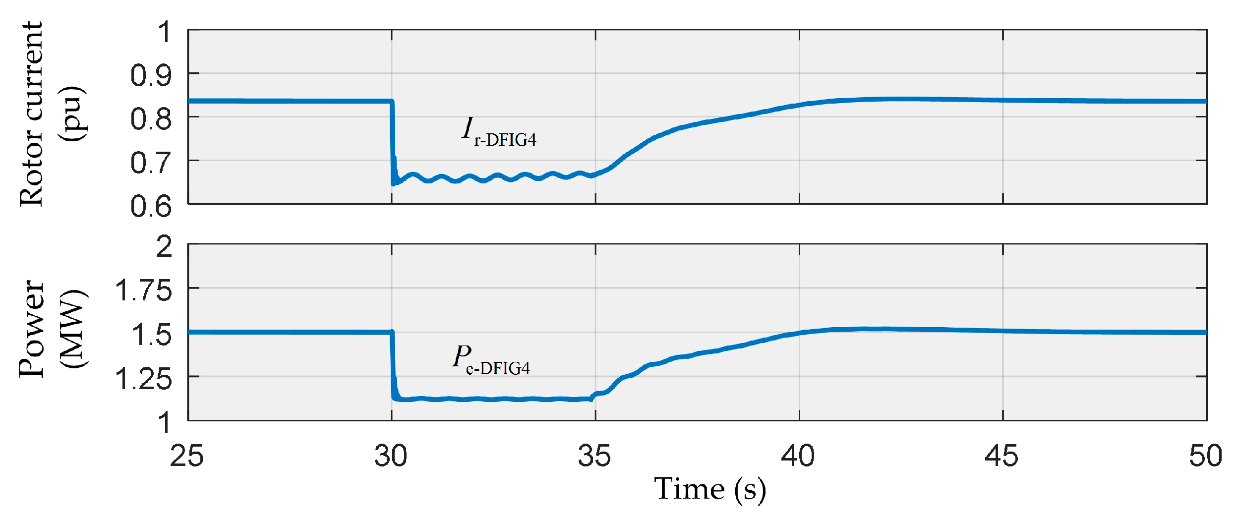
Feeder 3 is designed with a F1 fault and the wind speed at DFIG4 is 15 m/s. FA controls the circuit breakers L42 and L51 tripping for fault isolation at 30 s, and the island load is 1.12 MW. The tie-switch L52 closes after detection of synchronization conditions. Figure 11 and Figure 12 exhibit the changes in major electrical quantity at the grid side and the wind turbine side after a F1 fault.
- ①
- Grid-connection/Island Switching: the power supply from feeder 3 is cut off at 30 s, DFIG4, RMU4, tie-line 2 and loads constitute single island. DFIG3 enters into the islanding mode under ACS control, while the voltage of the tie-line 2 jitters to 1.1 pu for within 1 cycle. No sudden change in phase is observed. However, mainly due to the sudden change of power (from 1.5 MW to 1.12 MW), the voltage frequency of tie-line 2 shows a peak of 50.6 Hz less than allowed (51 Hz); the rotor current amplitude of DFIG4, rapidly reduces from 0.8 pu to 0.65 pu without overcurrent; the electromagnetic power of DFIG4 also rapidly adapts to the island loads of 1.12 MW. It can be seen that the DFIG4 under ACS control can seamlessly enter into the single island mode.
- ②
- Distant Synchronization Process: when the DFIG4 enters into the islanding mode with imbalanced power, the amplitude of remains relatively stable while fluctuates at a frequency of 1.5 Hz with a decreasing tendency; matches with the island loads of 1.12 MW without significant fluctuation basically; fluctuates around 50.1 Hz to cause the error of voltage phase between both sides of the tie-switch L62 reducing from 180° to 0°. It is obvious that the DFIG4 under ACS control can maintain the island stability and automatically create distant synchronization conditions.
- ③
- Island Grid-connection Process: the tie-switch L62 receives the FIS GOOSE message through FA as the circuit breakers L42 and L51 trip. reduces to 0° at 34.9 s, and L62 immediately closes to passive feeder 2 as the synchronization conditions are inspected locally through the synchronization check device, when the DFIG4 turns to the grid-connection status, and and rise gradually, during which, no vibrant fluctuation is experienced. The stable status before fault is recovered in about 10 s. In the meantime, and remain constant as they are clamped down by the voltage of feeder 2 after grid-connection, and reserves 0°; Current amplitude of tie-switch L62 rises from 0pu after closing without dash current, and enters into a stable status about 10 s later. It is obvious that the DFIG4 island under ACS control can securely recover the grid-connection status through coordination with L62 for local synchronous closing.
Scene 2: Unintentional Island with Multiple DFIGs Reconnecting to Passive Feeder
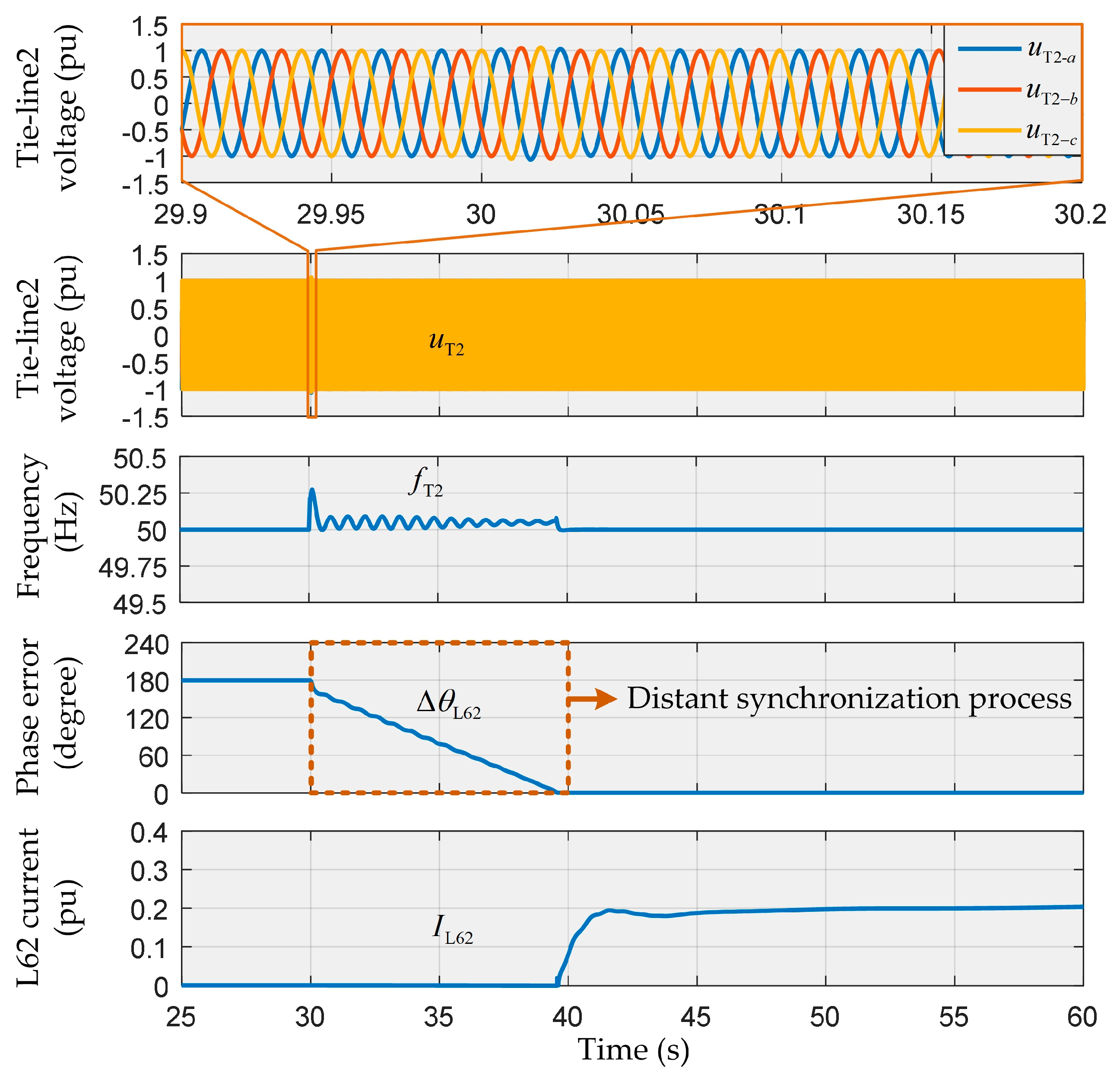
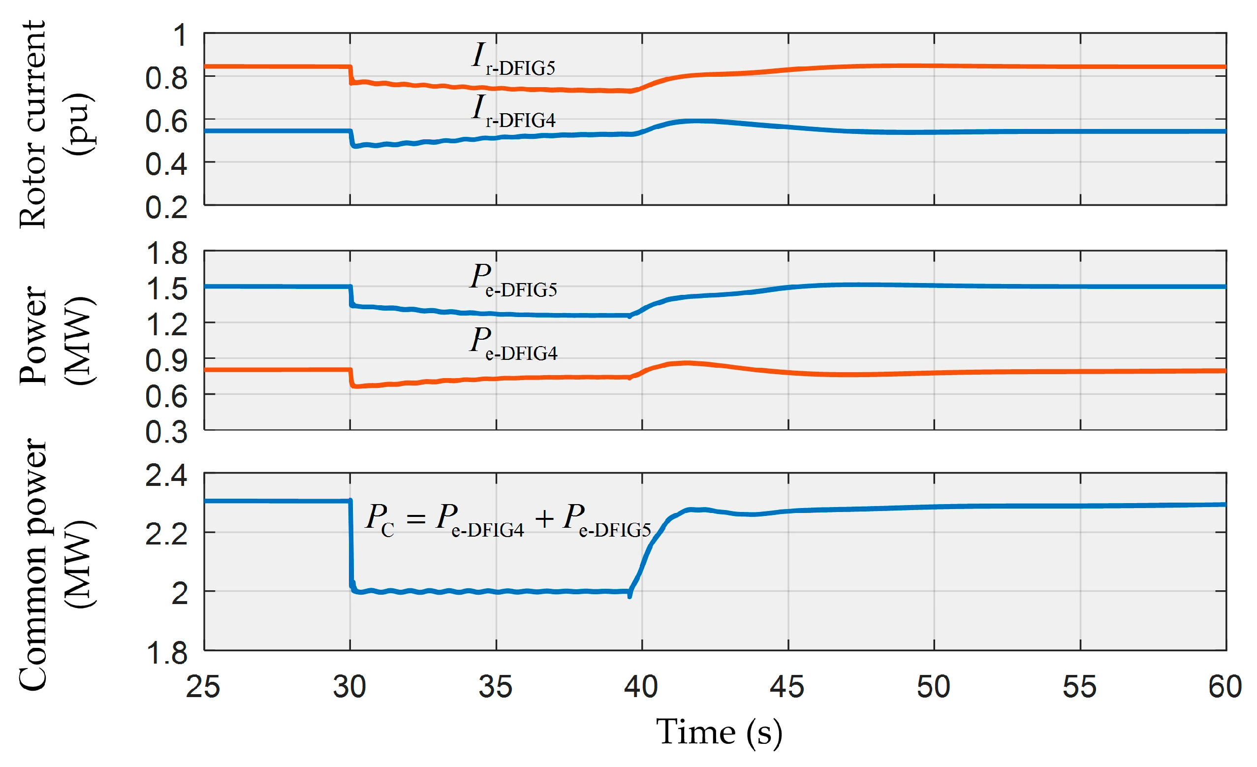
Feeder 3 is designed with a F2 fault and the wind speed is 10m/s at DFIG4 and 15 m/s at DFIG5. FA controls the circuit breakers L52 and S3 tripping for fault isolation at 30 s, and the island load is 2 MW. The tie-switch L62 closes after detection of synchronization conditions. Figure 13 and Figure 14 exhibit the changes in major electrical quantity at the grid side and the wind turbine side after a F2 fault.
- ①
- Grid-connection/Island Switching: as L52 and S3 trip, DFIG4, DFIG5, RMU4 and RMU5, tie-line 2 and loads constitute an island with two wind turbines. DFIG4 and DFIG5 enter into the islanding mode under ACS control, while the voltage of the tie-line 2 jitters slightly with a continuous waveform. Similarly, mainly due to the sudden change of power (from 2.3 MW to 2 MW), the voltage frequency of tie-line 2 shows a peak of 50.26 Hz below allowable; the rotor current amplitudes of DFIG4 and DFIG5 ( and ) rapidly change without overcurrent; the total electromagnetic power of DFIG4 and DFIG5 () also rapidly adapts to the island loads of 2 MW. It can be seen that the DFIG4 and DFIG5 under ACS control can seamlessly enter into the multiple islands mode.
- ②
- Distant Synchronization Process: when the DFIG4 and DFIG5 enter into the islanding mode with imbalanced power, the amplitude of remains relatively stable while and ; DFIG4 and DFIG5 automatically allocate and to maintain at 2MW constantly; fluctuates around 50.05 Hz and its undulatory property gradually weakens to cause the error of voltage phase between both sides of the tie-switch L62 reducing to . It is obvious that the island with DFIG4 and DFIG5 under ACS control can automatically create distant synchronization conditions.
- ③
- Island Grid-connection Process: the tie-switch L62 receives the FIS GOOSE message through FA as the circuit breakers L52 and S3 trip. reduces to at 39.6 s, and L62 immediately closes to passive feeder 2 as DFIG4 and DFIG5 switch to grid-connection mode, and rise gradually. The pre-fault stable status is recovered in about 15 s for and (1.5 MW and 0.8 MW). In the meantime, and remain constant as they are clamped down by the voltage of feeder 2 after grid-connection, and maintains at ; rises rapidly after closing without dash current, and enters into a stable status about 15 s later. It is obvious that the island with DFIG4 and DFIG5 under ACS control can securely recover the grid-connection status through coordination with L62 for local synchronous closing.
Scene 3: Unintentional Island with Multiple DFIGs Reconnecting to Active Feeder
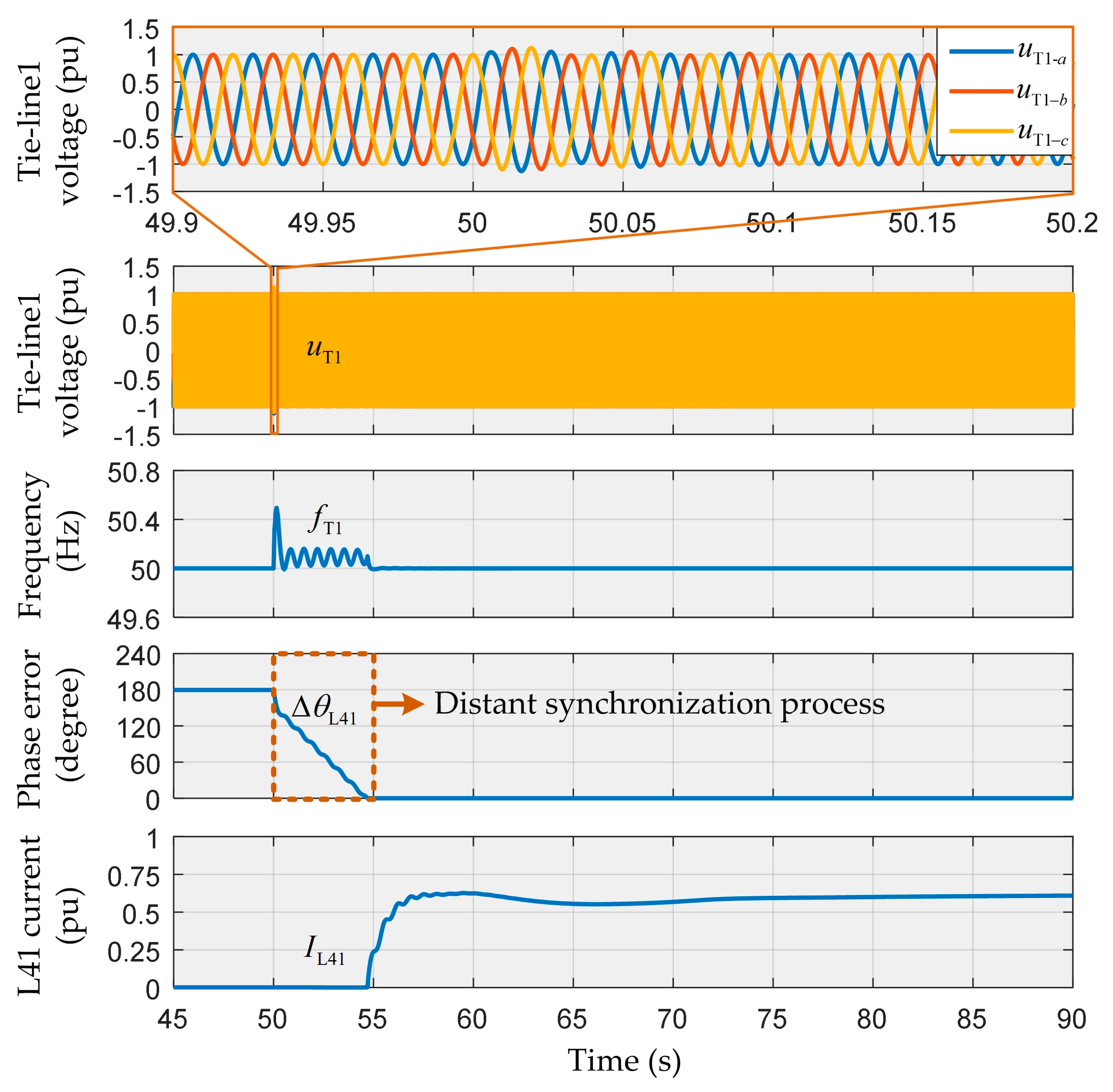
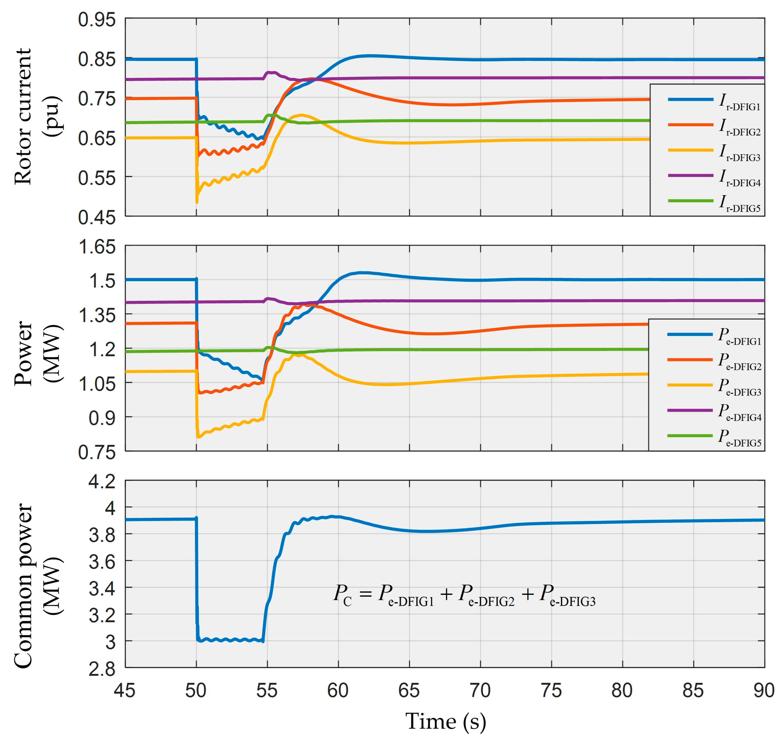
Feeder 3 is designed with a F3 fault and the wind speed is 15 m/s at DFIG1, 11.8 m/s at DFIG2 11.1 m/s at DFIG3, 12.1 m/s at DFIG4 and 11.4 m/s at DFIG5. FA controls the circuit breakers S1 and L11 tripping for fault isolation at 50 s, and the island load is 3 MW. The tie-switch L41 closes after detection of synchronization conditions with a F3 fault. Figure 15 and Figure 16 exhibit the changes in major electrical quantity at the grid side and the wind turbine side after a F3 fault.
- ①
- Grid-connection/Island Switching: the service is cut off at 50 s, DFIG1, DFIG2, DFIG3, RMU1, RMU2, RMU3, tie-line 1 and loads constitute an island with three wind turbines. DFIG1, DFIG2, and DFIG3 enter into the islanding mode under ACS control, while the voltage uT1 of the tie-line 1 jitters to 1.2 pu of the amplitude maximally for about 2.5 cycles, and the waveform transits flatly. Similarly, mainly due to the sudden change of power (from 3.9 MW to 3 MW), the voltage frequency of tie-line 1 shows a peak of 50.48 Hz, no more than the allowable value; the rotor current amplitudes of DFIG1, DFIG2, and DFIG3 (, and ) suddenly change without overcurrent; the electromagnetic powers of DFIG1, DFIG2, and DFIG3 (, and ) also rapidly change and their sum () matches with the island loads of 3 MW. It can be seen that the DFIG1, DFIG2, and DFIG3 under ACS control can seamlessly enter into the multiple wind turbine island mode.
- ②
- Distant Synchronization Process: when the DFIG1, DFIG2, and DFIG3 enter into the islanding mode with imbalanced power, the amplitude of remains relatively stable while , and close to each other; DFIG1, DFIG2, and DFIG3 automatically distribute , and to maintain at a relative stable value; fluctuates around 50.1 Hz to cause the error of voltage phase between both sides of the tie-switch L41 reducing to . It is obvious that the island with DFIG1, DFIG2, and DFIG3 under ACS control can automatically create distant synchronization conditions.
- ③
- Island Grid-connection Process: the tie-switch L41 receives the FIS GOOSE message through FA as the circuit breakers L11 and S1 trip, and immediately closes to active feeder 3 as the synchronization conditions () are detected locally through the synchronization check device at 54.7 s, when the DFIG1, DFIG2 and DFIG3 switch to the grid-connection status, and , and recover in an undulatory manner, during which, and fluctuate significantly; and fluctuate transitorily (about 5 s) when L41 closes, and then stabilizes; , and show the similar change tendency as the rotor currents, while and are subject to larger fluctuation as compared with the during grid-connection recovery, and and are shocked to a certain degree when L41 closes. In the meantime, and remain constant as they are clamped down by the voltage of feeder 3 after grid-connection, and maintains at ; Current amplitude of tie-switch L41 rises rapidly without dash current, and enters into a stable status after slight fluctuation. It is obvious that the DFIG1, DFIG2 and DFIG3 islands under ACS control can securely recover the grid-connection status through coordination with L41 for local synchronous closing, while DFIG4 and DFIG5 stabilize rapidly after temporary and limited shocks.
It can be seen from three fault scenes: the magnitude and fluctuation of the island system frequency are closely related to the power variation rate. The greater the power changes, the bigger the frequency magnitude changes (including the overshoot), the larger the frequency fluctuates. However, the frequency fluctuation during island operation will gradually decrease over time (e.g., Figure 13). Moreover, the more the frequency of the island system changes, the faster the synchronization conditions are met, so the islanding time of DFIG is closely related to the power change rate too. In addition, the DFIG under ACS control is a temporary island during the coordination with FA, which, on the one hand, helps solve the problem of power quality arising from the long-term islanding of the DFIG, and on the other hand, upgrades the traditional one-way power supply recovery mechanism from feeders to loads to the two-way power supply recovery mechanism from DG and feeders to loads. Therefore, the solution proposed in this paper can make the DFIG truly non-off-grid and more economical than other existing solutions.
It should be noted that, however, this paper mainly focuses on a situation that the total island loads are smaller than the total real-time capacity of all wind power generations in island, without consideration to other cases, including equivalent or larger relations. The underlying reasons shall be when the output of the wind turbine matches with the load, the wind turbine experiencing switching between grid-connection and island will not have obvious changes in status while the output of the wind turbine is smaller than the load, it has to coordinate with other power generation units (such as energy storage) to stabilize islands. Moreover, the compatibility between the FA technology and DFIG of the DN based on underground cables is another focus in this paper, while the FA technology for DN with overhead lines requires repeated reclosing, and different strategies to achieve compatibility with DFIG. In addition, this paper only studies DFIG, a type of DG. From the thought of DN-DG coordination, the solution proposed in this paper should have similar effect when applied to other types of DGs, such as photovoltaic, energy storage, permanent magnet synchronous generator, etc. However, if ACS proposed in this paper is to be applied to other DGs, appropriate modifications and adjustments may be required. Furthermore, for devices such as energy hub and energy router [36,37], which may be used in future smart grid, the idea in this paper should be helpful in solving the coordination problem between them and protection devices.
6. Conclusions
An adaptive control strategy of DFIG and coordination technology compatible with FA is proposed in this paper. The simulation is carried out based on MATLAB/Simulink and the results reveal that:
- ①
- The ACS proposed herein has similar power control characteristics as found in traditional PQ control that the DFIG can work effectively in grid-connection mode.
- ②
- As the FA isolates a feeder fault, one or multiple DFIGs under different wind speeds can achieve seamless switching between grid-connection/island modes under ACS control, and continuously supply power to partial local loads.
- ③
- During DFIG islanding, ACS’s differential regulation to frequency and power imbalance result in the automatic satisfaction of synchronization conditions at remote tie-switches.
- ④
- After FA fault isolation, the tie-switches can close based on local detection of synchronization conditions and the DFIG under ACS control can be securely grid-connected without establishing an additional communication system with the DN.
In general, the ACS and coordination technology in this paper realize the compatibility between DFIG and FA without DFIG shutdown and restart.
Author Contributions
Z.H. contributed to the project idea, the results discussion and conclusions. P.T. contributed to specific strategy, theoretical analysis, simulation experiment design and data analysis. Z.L. reviewed the final manuscript and the results discussion.
Funding
This research was funded by the National Natural Science Foundation of China (51567005), in part by the Guizhou Province Science and Technology Platform and Talent Project of China ([2017]5788/LH Word [2017]7230), in part by the Guizhou Province Science and Technology Plan Project of China ([2018]5615), in part by the National Natural Science Foundation of China (61963009).
Conflicts of Interest
The authors declare that there is no conflict of interests regarding the publication of this paper.
Appendix A

Table A1.
Nomenclature.
| Variable | Description |
|---|---|
| Electromagnetic power reference | |
| Actual output electromagnetic power | |
| Total electromagnetic power of DFIG island | |
| Electromagnetic power under traditional PQ control | |
| Electromagnetic power under ACS control | |
| Damping power | |
| Electromagnetic power of DFIGx | |
| Electric angular frequency of rotor | |
| Reference angular velocity of wind turbine | |
| Angular frequency of fundamental wave | |
| Angular frequency reference of grid | |
| Grid voltage angular frequency | |
| Slip angular frequency | |
| Stable speed of wind turbine at a certain operation point | |
| Synchronous angular frequency/ Stator voltage angular frequency | |
| Resonance term bandwidth of quasi-proportional resonant controller | |
| Island voltage angular frequency/ Inner potential angular frequency of stator | |
| & | Resistances of stator and rotor |
| & | Self-inductance of stator and rotor |
| Mutual inductance | |
| Voltage frequency of tie-line 1 | |
| Voltage frequency of tie-line 2 | |
| Inner potential of stator | |
| Inner potential amplitude of stator | |
| Space vectors of island voltage | |
| Space vectors of grid voltage | |
| Voltage of the tie-line 1 | |
| Voltage of the tie-line 2 | |
| & | Voltage space vectors of stator and rotor in stator static reference frame |
| , & | Three-phase excitation voltages of the rotor in rotor reference frame |
| Reference of stator voltage amplitude | |
| Actual stator voltage amplitude | |
| Synchronous reactance | |
| Mutual reactance | |
| & | Current space vectors of stator and rotor in stator static reference frame |
| , & | Reference of three-phase rotor excitation currents in rotor reference frame |
| , & | Actual excitation currents of rotor in rotor reference frame |
| Reference of rotor excitation current amplitude | |
| Rotor current amplitude of DFIGx | |
| Current amplitude of tie-switch L62 | |
| Current amplitude of tie-switch L41 | |
| Space vector reference of rotor excitation currents in rotor reference frame | |
| Error of voltage phase between both sides of tie-switch L62 | |
| Error of voltage phase between both sides of tie-switch L41 | |
| Inner potential control phase of stator | |
| Excitation current phase of rotor | |
| Inner potential phase of stator | |
| Rotor phase | |
| Proportional coefficient of quasi-proportional resonant controller | |
| Resonance term gain of quasi-proportional resonant controller | |
| Wind speed | |
| Pitch angle of blades | |
| Inertia time constant of power control | |
| Proportional coefficient of power control | |
| Damping coefficient of power control | |
| Mechanical energy capture by wind wheel | |
| Inherent mechanical inertia time constant of wind turbine | |
| Inherent mechanical damping coefficient of wind turbine | |
| & | Equivalent inertia and damping of DFIG under ACS control |
| & | Proportional and integral coefficient of torque control |
| & | Proportion and integral coefficient of voltage control |
Table A2.
Simulation system parameters.
| DFIG Machine | |||
| Parameter | Value | Parameter | Value |
| 0.023 pu | 1150 V | ||
| 0.016 pu | Rated power | 1.5 MW | |
| 3.08 pu | Stator voltage | 690 V | |
| 3.06 pu | Pole pairs | 3 | |
| 2.9 pu | Normal speed | 1.2 pu | |
| 4.96 | DC-link capacitor | 10,000 uF | |
| 1.5 | Rated frequency | 50 Hz | |
| ACS | |||
| 3 | 20 | ||
| 0.6 | 33 | ||
| 0.11 | |||
| 4.96 | 1 | ||
| 151 | 40 | ||
| DN | |||
| Rated voltage | 10 KV | Line inductance | 0.9337 × 10⁻³ H/km |
| Rated frequency | 50 Hz | Line capacitance | 12.74 × 10⁻⁹ F/km |
| Line resistance | 0.01273 Ω/km | ||
References
- João, P.S.; Catalão, S.; Rahimi, E.; Javadi, M.S.; Nezhad, A.E.; Lotfi, M.; Shafie-khah, M.; Catalão, J.P.S. Impact of distributed generation on protection and voltage regulation of distribution systems: A review. Renew. Sustain. Energy Rev. 2019, 105, 157–167. [Google Scholar]
- Blaabjerg, F.; Yang, Y.; Yang, D.; Wang, X. Distributed Power-Generation Systems and Protection. Proc. IEEE 2017, 105, 1311–1331. [Google Scholar] [CrossRef]
- Roy, N.K.; Pota, H.R. Current Status and Issues of Concern for the Integration of Distributed Generation into Electricity Networks. IEEE Syst. J. 2015, 9, 933–944. [Google Scholar] [CrossRef]
- Monadi, M.; Amin Zamani, M.; Ignacio Candela, J.; Luna, A.; Rodriguez, P. Protection of AC and DC distribution systems Embedding distributed energy resources: A comparative review and analysis. Renew. Sustain. Energy Rev. 2015, 51, 1578–1593. [Google Scholar] [CrossRef]
- Kennedy, J.; Ciufo, P.; Agalgaonkar, A. A review of protection systems for distribution networks embedded with renewable generation. Renew. Sustain. Energy Rev. 2016, 58, 1308–1317. [Google Scholar] [CrossRef]
- Nikolaidis, V.C.; Papanikolaou, E.; Safigianni, A.S. A Communication-Assisted Overcurrent Protection Scheme for Radial Distribution Systems with Distributed Generation. IEEE Trans. Smart Grid. 2016, 7, 114–123. [Google Scholar] [CrossRef]
- Bansal, R. Power System Protection in Smart Grid Environment, 1st ed.; CRC Press: Boca Raton, FL, USA, 2019. [Google Scholar]
- Norshahrani, M.; Mokhlis, H.; Abu Bakar, A.; Jamian, J.; Sukumar, S. Progress on Protection Strategies to Mitigate the Impact of Renewable Distributed Generation on Distribution Systems. Energies 2017, 10, 1864. [Google Scholar] [CrossRef]
- Sajadi, A.; Strezoski, L.; Strezoski, V.; Prica, M.; Loparo, K.A. Integration of renewable energy systems and challenges for dynamics, control, and automation of electrical power systems. Wires Energy Environ. 2019, 8, e321. [Google Scholar] [CrossRef]
- Vyas, S.; Kumar, R.; Kavasseri, R. Data analytics and computational methods for anti-islanding of renewable energy based Distributed Generators in power grids. Renew. Sustain. Energy Rev. 2017, 69, 493–502. [Google Scholar] [CrossRef]
- Peixin, Y.; Peichao, Z. A Survey on Interconnection Protection of Distributed Resource. Power Syst. Techn. 2016, 06, 1888–1895. [Google Scholar]
- Manditereza, P.T.; Bansal, R. Renewable distributed generation: The hidden challenges—A review from the protection perspective. Renew. Sustain. Energy Rev. 2016, 58, 1457–1465. [Google Scholar] [CrossRef]
- Motter, D.; de Melo Vieira, J.C. The Setting Map Methodology for Adjusting the DG Anti-Islanding Protection Considering Multiple Events. IEEE Trans. Power Deliv. 2018, 33, 2755–2764. [Google Scholar] [CrossRef]
- Zidan, A.; Khairalla, M.; Abdrabou, A.M.; Khalifa, T.; Shaban, K.; Abdrabou, A.; El Shatshat, R.; Gaouda, A.M. Fault Detection, Isolation, and Service Restoration in Distribution Systems: State-of-the-Art and Future Trends. IEEE Trans. Smart Grid 2017, 8, 2170–2185. [Google Scholar] [CrossRef]
- Zhan, H.; Wang, C.; Wang, Y.; Yang, X.; Zhang, X.; Wu, C.; Chen, Y. Relay Protection Coordination Integrated Optimal Placement and Sizing of Distributed Generation Sources in Distribution Networks. IEEE Trans. Smart Grid 2016, 7, 55–65. [Google Scholar] [CrossRef]
- Abdel-Ghany, H.A.; Azmy, A.M.; Elkalashy, N.I.; Rashad, E.M. Optimizing DG penetration in distribution networks concerning protection schemes and technical impact. Electr. Power Syst. Res. 2015, 128, 113–122. [Google Scholar] [CrossRef]
- Badran, O.; Mekhilef, S.; Mokhlis, H.; Dahalan, W. Optimal reconfiguration of distribution system connected with distributed generations: A review of different methodologies. Renew. Sustain. Energy Rev. 2017, 73, 854–867. [Google Scholar] [CrossRef]
- Xyngi, I.; Popov, M. An Intelligent Algorithm for the Protection of Smart Power Systems. IEEE Trans. Smart Grid 2013, 4, 1541–1548. [Google Scholar] [CrossRef]
- Wheeler, K.A.; Elsamahy, M.; Faried, S.O. A Novel Reclosing Scheme for Mitigation of Distributed Generation Effects on Overcurrent Protection. IEEE Trans. Power Deliv. 2018, 33, 981–991. [Google Scholar] [CrossRef]
- Zhu, Z.; Xu, B.; Brunner, C.; Yip, T.; Chen, Y. IEC 61850 Configuration Solution to Distributed Intelligence in Distribution Grid Automation. Energies 2017, 10, 528. [Google Scholar] [CrossRef]
- Ling, W.; Liu, D.; Yang, D.; Sun, C. The situation and trends of feeder automation in China. Renew. Sust. Energy Rev. 2015, 50, 1138–1147. [Google Scholar] [CrossRef]
- Chenghong, T.; Zhihong, Y.; Bin, S.; Yajun, Z. A Method of Intelligent Distributed Feeder Automation for Active Distribution Network. Autom. Electr. Power Syst. 2015, 9, 101–106. [Google Scholar]
- Wanshui, L.; Dong, L.; Yiming, L.; Wenpeng, Y. Model of intelligent distributed feeder automation based on IEC 618510. Autom. Electr. Power Syst. 2012, 36, 90–95. [Google Scholar]
- Tanvir, A.; Merabet, A.; Beguenane, R. Real-Time Control of Active and Reactive Power for Doubly Fed Induction Generator (DFIG)-Based Wind Energy Conversion System. Energies 2015, 8, 10389–10408. [Google Scholar] [CrossRef]
- Shukla, R.D.; Tripathi, R.K. A novel voltage and frequency controller for standalone DFIG based Wind Energy Conversion System. Renew. Sustain. Energy Rev. 2014, 37, 69–89. [Google Scholar] [CrossRef]
- Lin, L.; Xibin, S.; Zongxun, S. Operation mode analysis of micro-grid grid-connected and island based on DFIG control method. Power Syst. Protect. Control 2017, 45, 158–163. [Google Scholar]
- Hosseini, S.M.; Carli, R.; Dotoli, M. Robust Day-Ahead Energy Scheduling of a Smart Residential User Under Uncertainty. In Proceedings of the 2019 18th European Control Conference, Naples, Italy, 25–28 June 2019; pp. 935–940. [Google Scholar]
- Sperstad, I.; Korpås, M. Energy Storage Scheduling in Distribution Systems Considering Wind and Photovoltaic Generation Uncertainties. Energies 2019, 12, 1231. [Google Scholar] [CrossRef]
- Sitharthan, R.; Karthikeyan, M.; Sundar, D.S.; Rajasekaran, S. Adaptive hybrid intelligent MPPT controller to approximate effectual wind speed and optimal rotor speed of variable speed wind turbine. ISA. Trans. 2019, in press. [Google Scholar] [CrossRef]
- Miller, N.W.; Sanchez-Gasca, J.J.; Price, W.W.; Delmerico, R.W. Dynamic modeling of GE 1.5 and 3.6 MW wind turbine-generators for stability simulations. In Proceedings of the IEEE Power Engineering Society General Meeting (IEEE Cat. No.03CH37491), Toronto, ON, Canada, 13–17 July 2003; pp. 1977–1983. [Google Scholar]
- Pena, R.; Clare, J.C.; Asher, G.M. Doubly fed induction generator uising back-to-back PWM converters and its application to variable- speed wind-energy generation. IEE Proc. Electr. Power Appl. 1996, 3, 231–241. [Google Scholar] [CrossRef]
- Wang, S.; Hu, J.; Yuan, X. Virtual Synchronous Control for Grid-Connected DFIG-Based Wind Turbines. IEEE J. Emerg. Sel. Top. Power Electron. 2015, 3, 932–944. [Google Scholar] [CrossRef]
- Ye, T.; Dai, N.; Lam, C.; Wong, M.; Guerrero, J.M. Analysis, Design, and Implementation of a Quasi-Proportional-Resonant Controller for a Multifunctional Capacitive-Coupling Grid-Connected Inverter. IEEE Trans. Ind. Appl. 2016, 52, 4269–4280. [Google Scholar] [CrossRef]
- Holmes, D.G.; Lipo, T.A.; McGrath, B.P.; Kong, W.Y. Optimized Design of Stationary Frame Three Phase AC Current Regulators. IEEE Trans. Power Electr. 2009, 24, 2417–2426. [Google Scholar] [CrossRef]
- Clark, K.; Miller, N.W.; Sanchez-Gasca, J.J. Modeling of GE Wind Turbine-Generators for Grid Studies; General Electric International, Inc.: Schenectady, NY, USA, 2009. [Google Scholar]
- Carli, R.; Dotoli, M. Decentralized control for residential energy management of a smart users microgrid with renewable energy exchange. IEEE/CAA J. Autom. Sin. 2019, 6, 641–656. [Google Scholar] [CrossRef]
- Geidl, M.; Koeppel, G.; Favre-Perrod, P.; Klockl, B.; Andersson, G.; Frohlich, K. Energy hubs for the future. IEEE Power Energy Mag. 2007, 5, 24–30. [Google Scholar] [CrossRef]
Figure 1.
Active distribution network system under study.

Figure 2.
DN-DG compatibility solution.

Figure 3.
DFIG system.

Figure 4.
Structure diagram of proposed ACS.

Figure 5.
Small signal equivalent model of DFIG under ACS control.

Figure 6.
Equivalent inertia/damping model of DFIG under ACS control.

Figure 7.
ACS control parameter’s impact on DFIG equivalent inertia/damping: (a) Maximal equivalent inertia with different inertia time constant and proportional coefficient; (b) Maximal equivalent damping with different inertia time constant, damping and proportional coefficient.
Figure 7.
ACS control parameter’s impact on DFIG equivalent inertia/damping: (a) Maximal equivalent inertia with different inertia time constant and proportional coefficient; (b) Maximal equivalent damping with different inertia time constant, damping and proportional coefficient.

Figure 8.
Principles of distant synchronization.

Figure 9.
Coordination technology.

Figure 10.
Electromagnetic power waveforms of DFIG under PQ control and proposed ACS control.

Figure 11.
Changes in electrical quantity at the grid side after a F1 fault.

Figure 12.
Changes in electrical quantity at the wind turbine side after a F1 fault.

Figure 13.
Changes in electrical quantity at the grid side after a F2 fault.

Figure 14.
Changes in electrical quantity at the wind turbine side after a F2 fault.

Figure 15.
Changes in electrical quantity at the grid side after a F3 fault.

Figure 16.
Changes in electrical quantity at the wind turbine side after a F6 fault.

© 2019 by the authors. Licensee MDPI, Basel, Switzerland. This article is an open access article distributed under the terms and conditions of the Creative Commons Attribution (CC BY) license (http://creativecommons.org/licenses/by/4.0/).
Share and Cite
MDPI and ACS Style
Tian, P.; Li, Z.; Hao, Z. A Doubly-Fed Induction Generator Adaptive Control Strategy and Coordination Technology Compatible with Feeder Automation. Energies 2019, 12, 4463. https://0-doi-org.brum.beds.ac.uk/10.3390/en12234463
AMA Style
Tian P, Li Z, Hao Z. A Doubly-Fed Induction Generator Adaptive Control Strategy and Coordination Technology Compatible with Feeder Automation. Energies. 2019; 12(23):4463. https://0-doi-org.brum.beds.ac.uk/10.3390/en12234463
Chicago/Turabian StyleTian, Peng, Zetao Li, and Zhenghang Hao. 2019. "A Doubly-Fed Induction Generator Adaptive Control Strategy and Coordination Technology Compatible with Feeder Automation" Energies 12, no. 23: 4463. https://0-doi-org.brum.beds.ac.uk/10.3390/en12234463
Note that from the first issue of 2016, this journal uses article numbers instead of page numbers. See further details here.