Article

Experimental Study on B-Spline-Based Modulation Schemes Applied in Multilevel Inverters for Electric Drive Applications

Dipartimento di Ingegneria, University of Palermo, Viale delle Scienze, Parco d’Orleans, 90128 Palermo, Italy
*
Author to whom correspondence should be addressed.
Submission received: 25 October 2019 / Revised: 15 November 2019 / Accepted: 26 November 2019 / Published: 27 November 2019
(This article belongs to the Special Issue Multilevel Power Converters Control and Modulation Techniques)

Abstract

:
This work presents the design, simulation, and experimental validation of new B-Spline-based modulation techniques applied to a Multilevel Power Inverter (MPI), particularly focusing the attention on the harmonic content of the output voltages of the inverter. Simulation and experimental results are proposed and discussed, mainly describing the potential benefits, such as the increase of the multi-level operation of the converter, and drawbacks (low-order harmonics) related to the adoption of B-Spline functions for multilevel inverters applied in the field of electrical drives.

1. Introduction

In recent years, the electrical drives have reached a very wide range of industry applications, due to the significant improvement in terms of performances of both innovative electric motors and power converters. Recently, the energy consumption determined by the electrical drives corresponds to the 46% of the global energy demand [1,2,3,4] and, therefore, new optimization techniques and control algorithms have been conceived in order to either maximize the efficiency or reduce the harmonic content of the entire drive [5].
As for the power converters, the multilevel inverters represent a suitable solution especially for high-power/medium-voltage applications [6,7,8,9,10,11]. One of the advantages bought by Multilevel Power Inverters (MPI) adopted for electrical drives with respect to traditional three-phase converters is represented by the lower harmonic content of their output voltage waveform [12].
Moreover, it is well known that the traditional modulation schemes use triangular waveforms as carrier signals. In different studies the pulse-width modulation (PWM) techniques are modified in order to improve the performances of the power converter. Such improvements are mainly focused on adding specific signals on the reference signal (e.g., Switching Frequency Optimal, SFO, or Total Harmonic Injection, THI), optimizing the features of the duty-cycle [13,14] or increasing the switching frequency [15,16,17]. In particular, the use of carrier signals with different harmonic content with respect to the triangular waveform allows changing the harmonic content in the output voltage waveform of the converter.
The B-Spline functions are commonly used in the approximation theory [18,19], defined piecewise by polynomials. The first study on the modulation techniques by using B-Spline functions can be found in [20], which is focused on the Total Harmonic Distortion (THD%) reduction by changing the carrier signal waveform from a traditional triangular shape to a B-Spline function, based on the interpretation of the triangular waveform as a periodic form of the second order Cardinal B-Spline function. By increasing the order of the carrier signal, the output harmonic content is reduced and, therefore, the fundamental component is improved. Nevertheless, the implementation of the B-Spline-based control algorithm is challenging, mainly due to the high execution time required for the calculation of the related functions [21,22]. Genduso et al. [23,24] presented a novel real-time algorithm that eliminated the problem concerning the B-Spline recursive evaluation through the adoption of specifically designed duty cycle expressions.
A detailed analysis regarding the spectra of the output voltage for traditional three-phase converters is reported in [25], in which it is demonstrated that the use of B-Spline-based modulation techniques increases the low-order harmonic components. With regards to the multilevel converters, there is a lack in terms of multicarrier modulation schemes based on B-Spline functions as carrier signals, where only few works are reported in literature [26,27]. Therefore, it can be stated that the adoption of B-Spline functions as carrier signals for multilevel converters has not been widely studied yet.
In this context, this work presents the design, simulation, and experimental validation of new B-Spline-based modulation techniques applied to a Cascaded H-Bridge Multilevel Inverter (CHBMI) for electric drive applications, particularly focusing the attention on the harmonic content of the output voltages of the inverter, corresponding to the supply voltages for the motor. More in detail, this paper is structured as follows: Section 2 reports a description of the B-Spline functions, whereas Section 3 presents the related modulation techniques applied for single-phase and three-phase multilevel inverters. The simulation and the experimental results are discussed in Section 4 and Section 5.

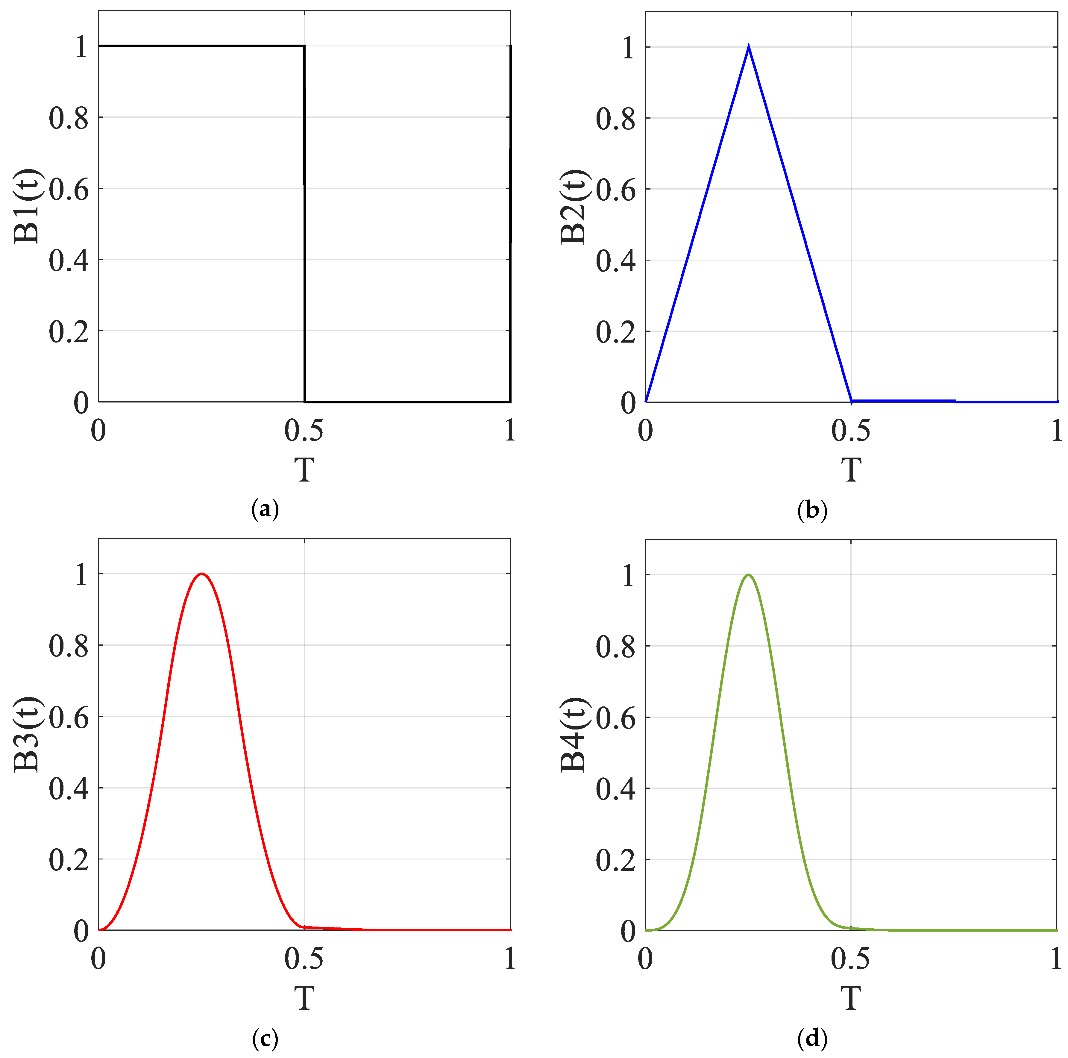
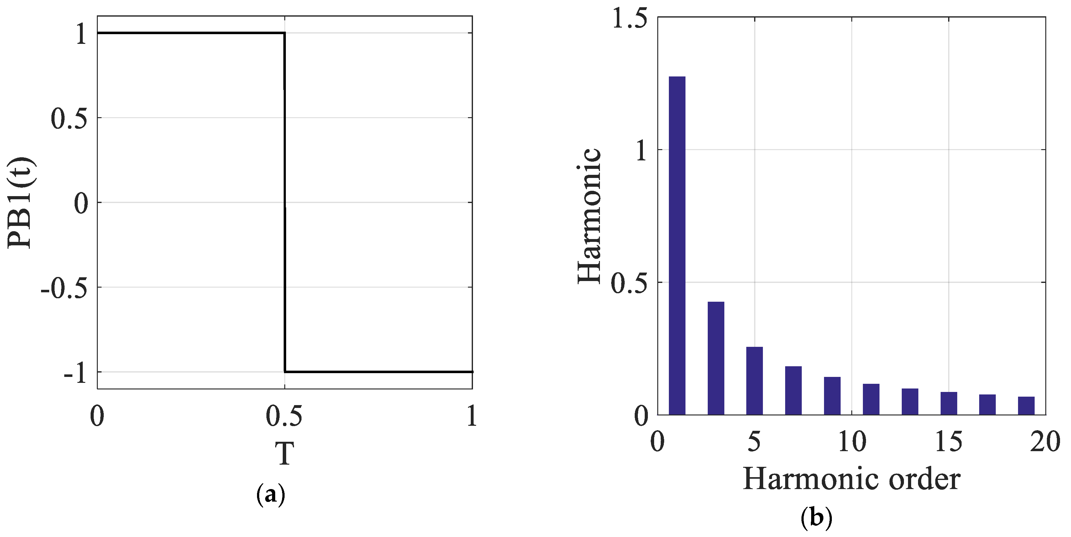
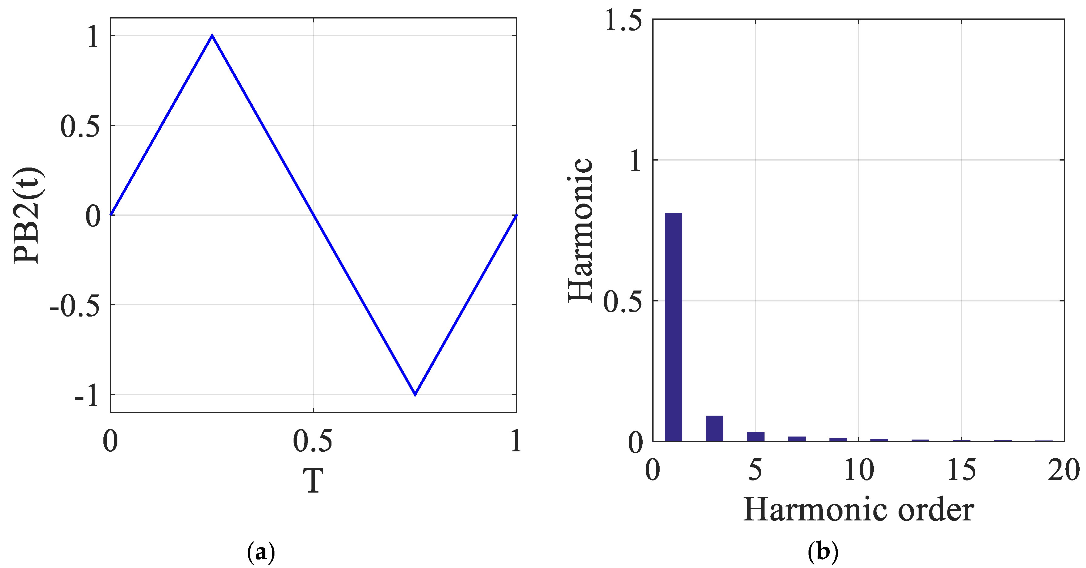
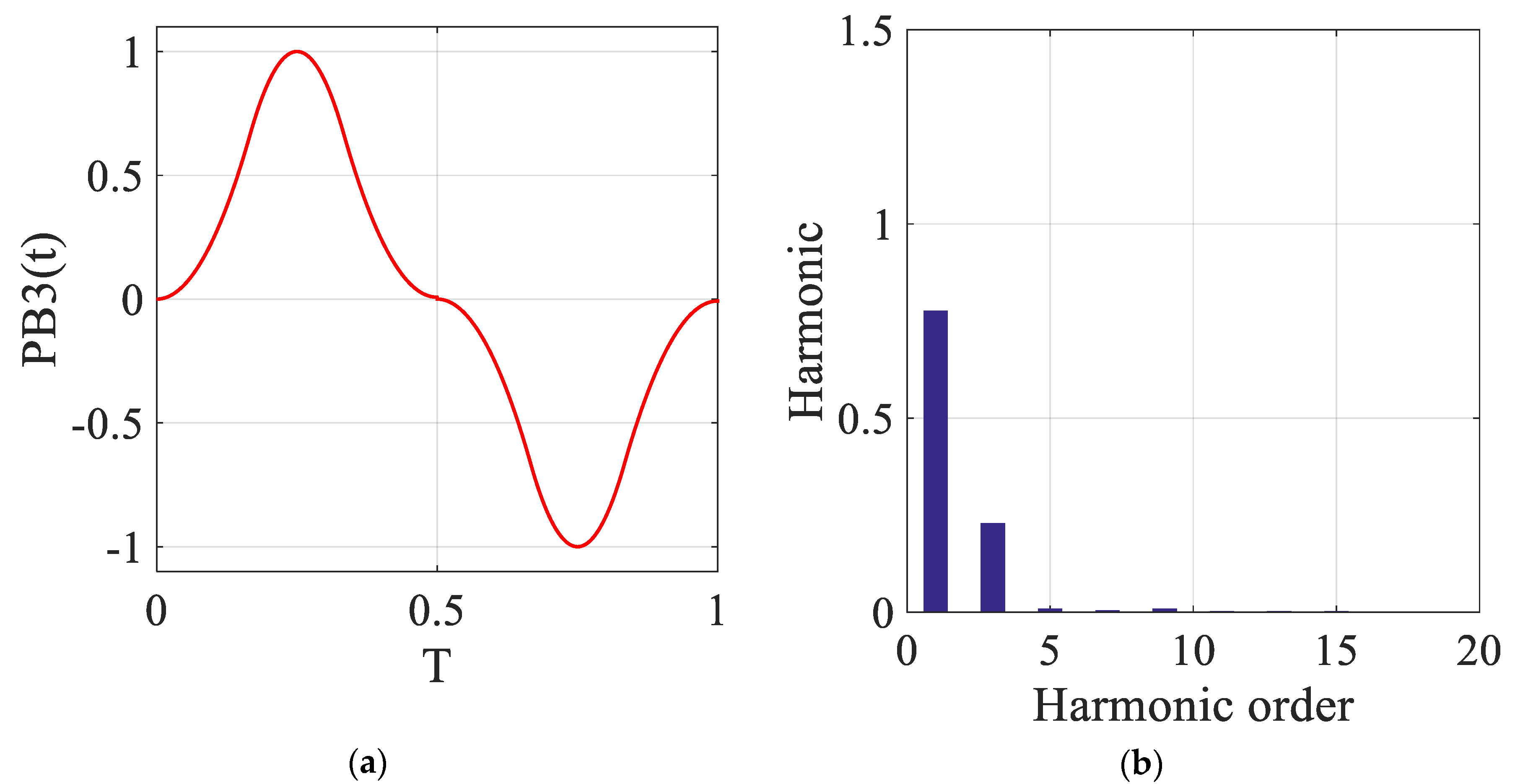
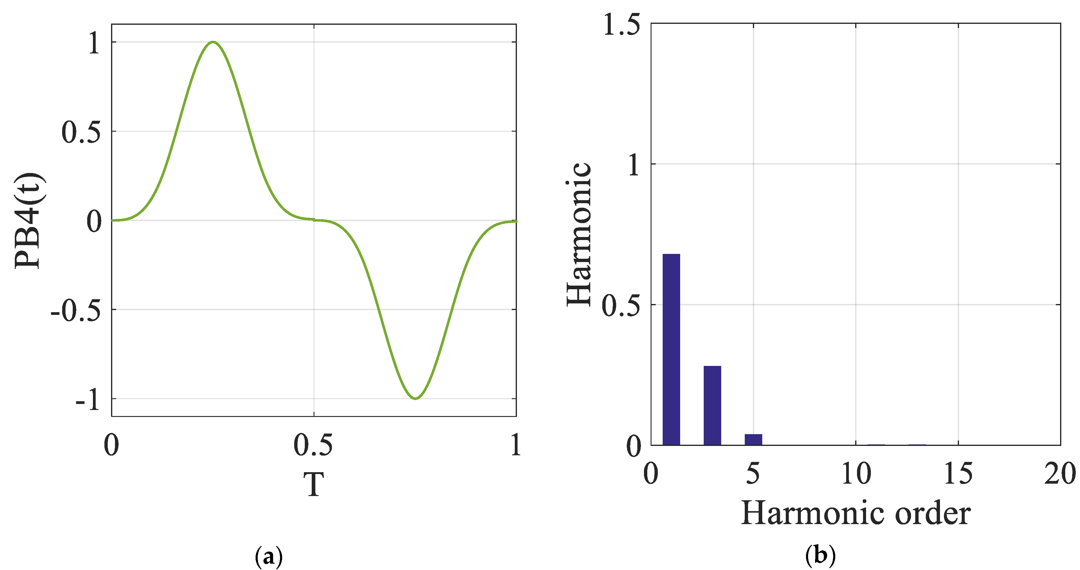
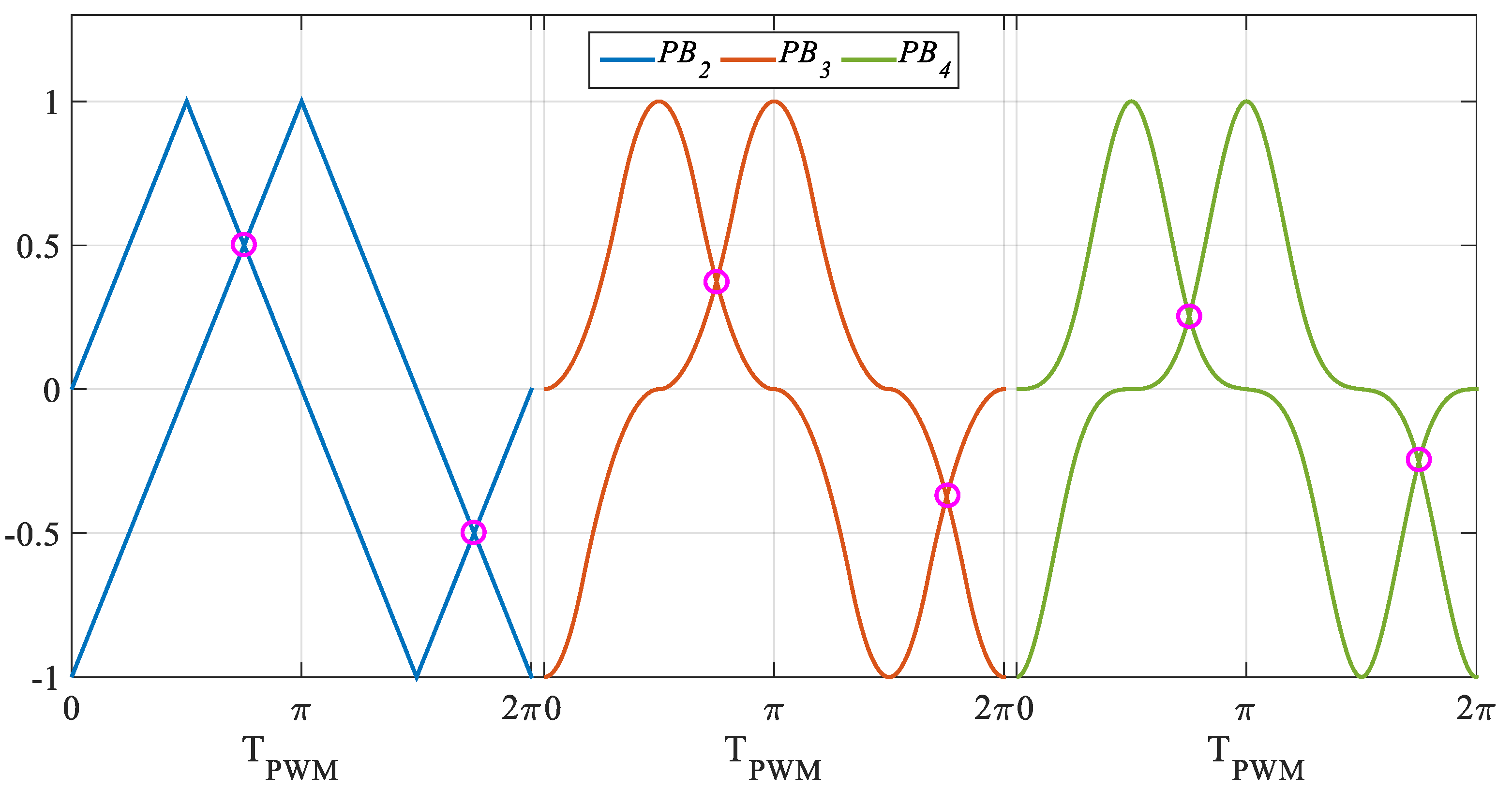
2. B-Spline Functions

The Cardinal B-Splines adopted in this work are determined from the order-fold convolution procedure, finalized to obtain the highest order of B-Spline function. B-Spline are used in large fields of engineering and science, from the multiresolution analysis to wavelet transform and the resolution of Maxwell’s equations [28,29,30]. In detail, the Cardinal B-Spline function of the first order, namely B1(t), by referring to a period from 0 to 1, is defined as follows:
B 1 ( t ) = { 1 0 < t < 0.5 0 0.5 < t < 1
By adopting the procedure of order-fold convolution, the m-order Cardinal B-Spline function is defined as follows:
B m ( t ) = B m 1 ( t ) B 1 ( t ) = B m 1 ( τ ) B 1 ( t τ ) d τ
This procedure allows the obtainment of the B-Spline functions shown in Figure 1a–d.
The general m-order Cardinal B-Spline function can be converted to a periodic function:
P B m ( t ) = { B m ( t ) i f 0 < t < T 2 B m ( t T 2 ) i f T 2 < t < T ,
where PBm(t) is the periodic form of the cardinal B-Spline Bm(t) and T is the period of the periodic B-Spline function. The periodic functions referred to the first, second, third and fourth-order Cardinal B-Splines with their related harmonic spectra are shown in Figure 2, Figure 3, Figure 4 and Figure 5, respectively. From these characteristics, it can be noticed that the PB2 function is represented by the traditional triangular waveform commonly used in the classic modulation techniques. Moreover, the comparison between the proposed trends reveals the different harmonic content for each of the plotted B-Spline functions, leading, therefore, to the presence of different harmonic components in terms of output voltages.
The progressive reduction of the order of harmonics, with the increase in the order of derivability of the function used, has been explored in many fields of electrical engineering [30,31,32,33,34].

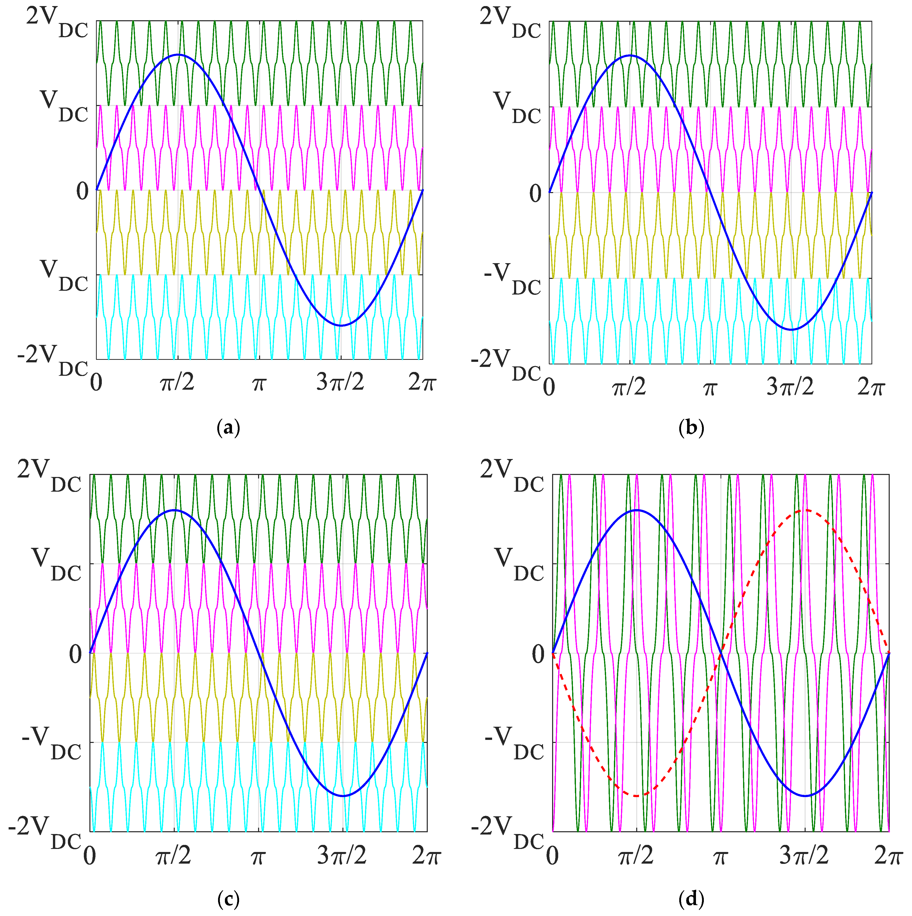
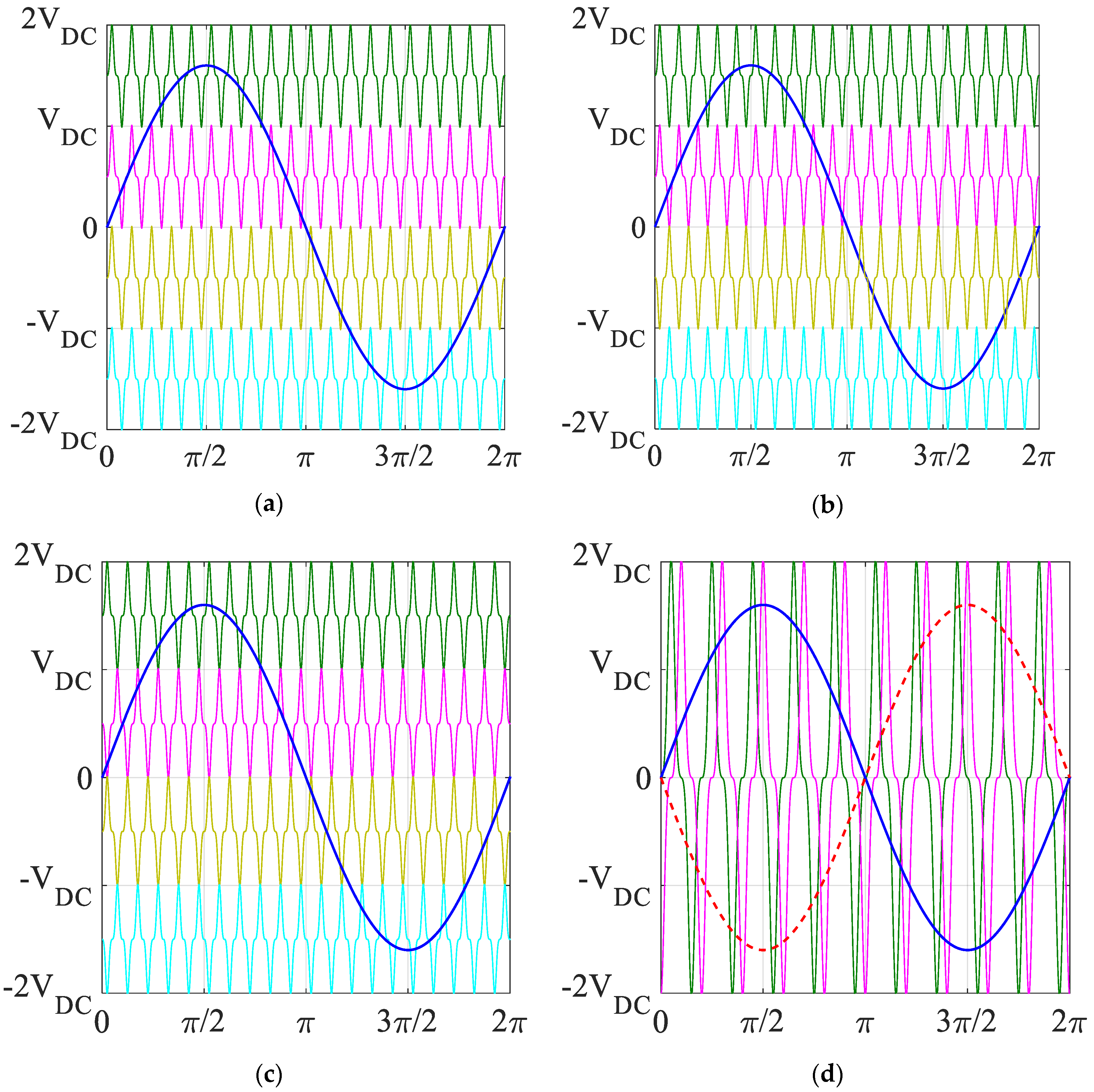
3. B-Spline Based Modulation Schemes for Single-Phase and Three-Phase Multilevel Inverters

This section describes the new B-Spline-based multicarrier modulation techniques applied both for single-phase and three-phase multilevel converters, capable of supplying both single-phase and three-phase electrical motors [26,27].

3.1. Single-Phase Multilevel Inverters

Generally, the multicarrier modulation schemes can be defined in dependence of both the reference and the carrier signals. In particular, the Authors of [35,36,37] presented four different techniques strictly related to the carrier signals: Phase Disposition (PD), Phase Opposition Disposition (POD), Alternative Phase Opposition Disposition (APOD), and Phase Shifted (PS). For each technique, the proposed modulation schemes with third order (PB3) and fourth order (PB4) B-Spline functions with sinusoidal reference are shown in Figure 6 and Figure 7, respectively, obtaining eight new multicarrier modulation schemes.
With respect to the traditional modulation schemes, the intersection between the reference and the carrier signals is different and, therefore, different harmonic components and distinctive values of THD% for each modulation scheme are expected.
With regards to the Sinusoidal PS, this technique is characterized by two triangular waveforms as carrier signals with mutual phase shift equal to π/2 and with related intersection at a half of the peak value. Thus, these intersections represent the change of operation of the converter from three levels to five levels. Figure 8 shows the comparison between the PS carrier signals for a five-level converter obtained with PB2 (blue curves), PB3 (red curves), and PB4 (green curves). It can be noticed that the intersection points among the carrier signals (signed with purple circles) is different for each technique and, particularly, it is lower for PB3 and PB4 (equal to 0.37 and 0.26, respectively). Thus, if compared with PB2, the five-level voltage will appear for lower values of the modulation index.

3.2. Three-Phase Multilevel Inverters

The new B-Spline-based modulation techniques for three-phase inverters represent the evolution of the schemes previously described and referred to single-phase topologies. Specifically, these techniques adopt PS as carrier signals and different reference signals, such as reported in [27].
The first modulation schemes take into account a three-phase sinusoidal reference with SPB3 and SPB4 B-Spline functions, as plotted in Figure 9a,b, respectively. Other modulation schemes can be obtained by combining a THI reference signal with the third and fourth order B-Spline functions, as shown in Figure 10a,b. Finally, Figure 11 shows the modulation schemes based on the combination of an SFO reference signal with the PB3 and PB4 functions.
In conclusion, the B-spline based modulation schemes for single-phase and three-phase multilevel inverters have been presented in this section. In the next section, simulation results and discussions are reported.

4. Simulation Results and Discussion

This section provides the simulation results obtained by implementing the modulation techniques previously reported in Section 3 for both single-phase and three-phase inverters. In particular, the main purpose of this analysis is the determination of the harmonic content on the output voltage of the converter for each of the proposed new modulation schemes. The comparison between these techniques has been achieved by considering the Total Harmonic Distortion (THD%) for different values of the modulation index M, in order to determine the best solution in terms of harmonic content. The THD% parameter can be defined as follows:
T H D % = V r m s 2 V r m s , 1 2 V r m s , 1 2 · 100 .
where Vrms is the root mean square (rms) value of the phase voltage and Vrms,1 is the rms value of its fundamental harmonic. As for the three-phase topology, the THD% line voltage has been considered. The simulations have been carried out by means of the Matlab-Simulink® environment with the simulation parameters reported in Table 1.

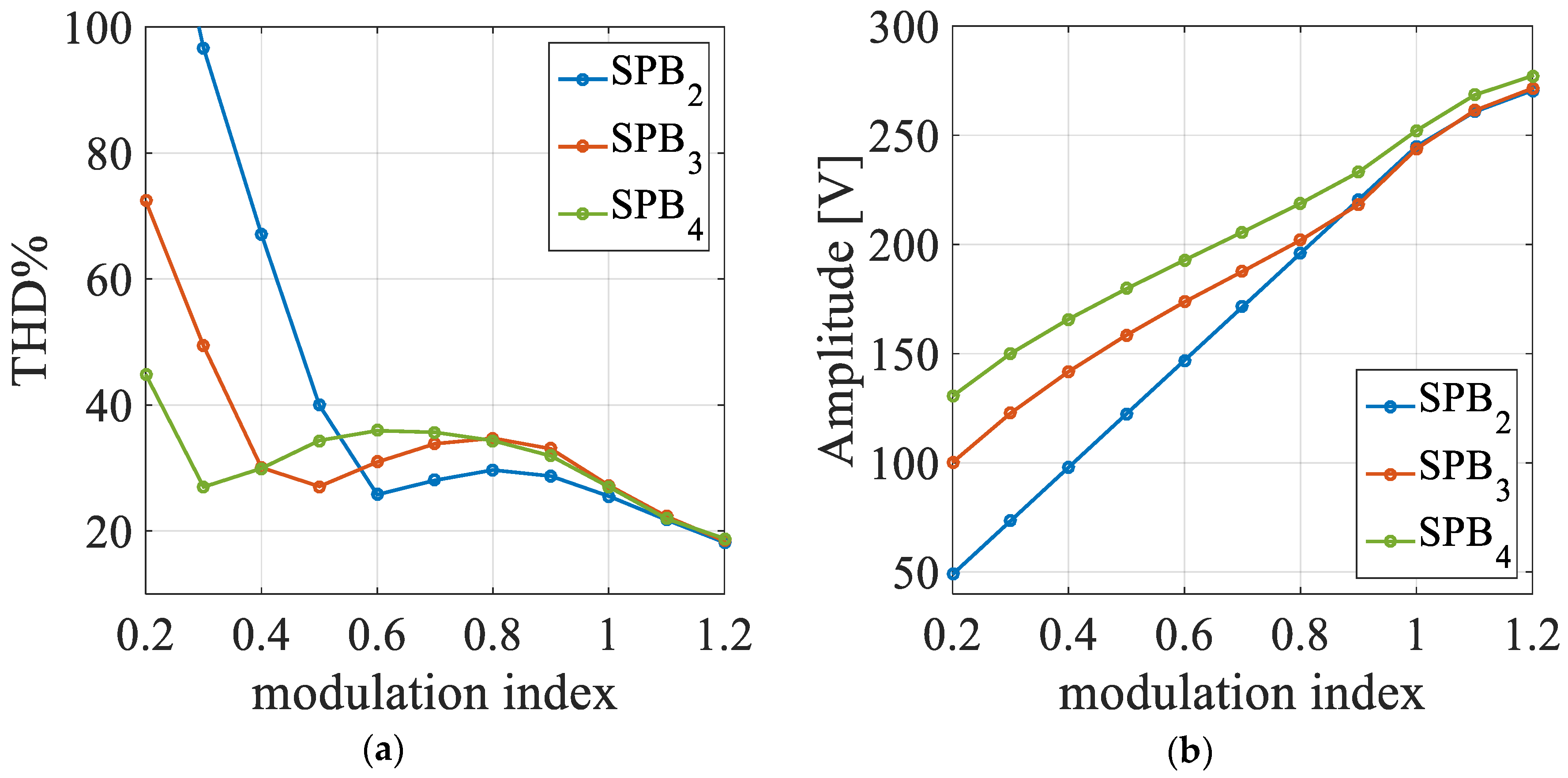
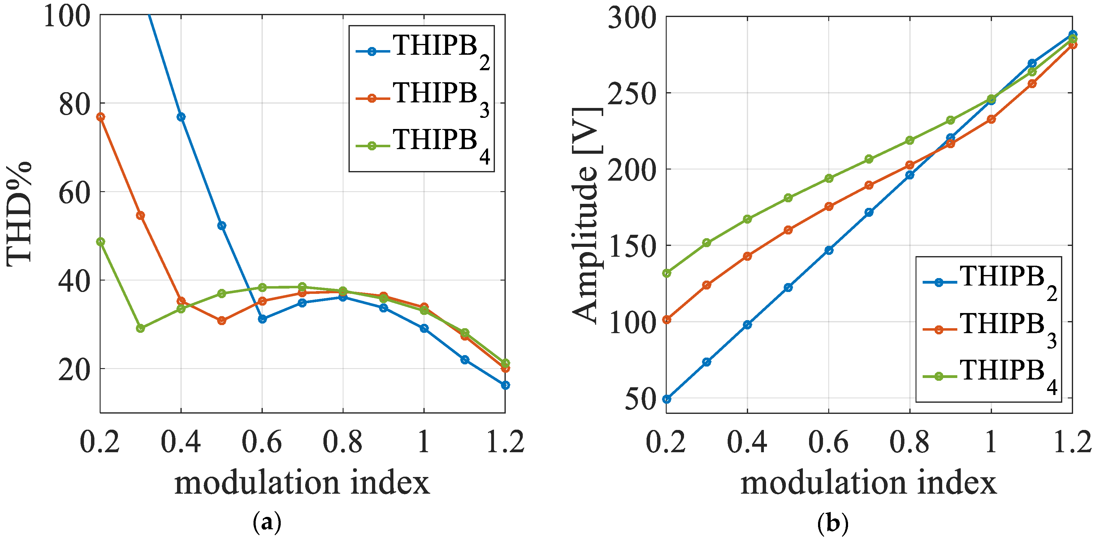
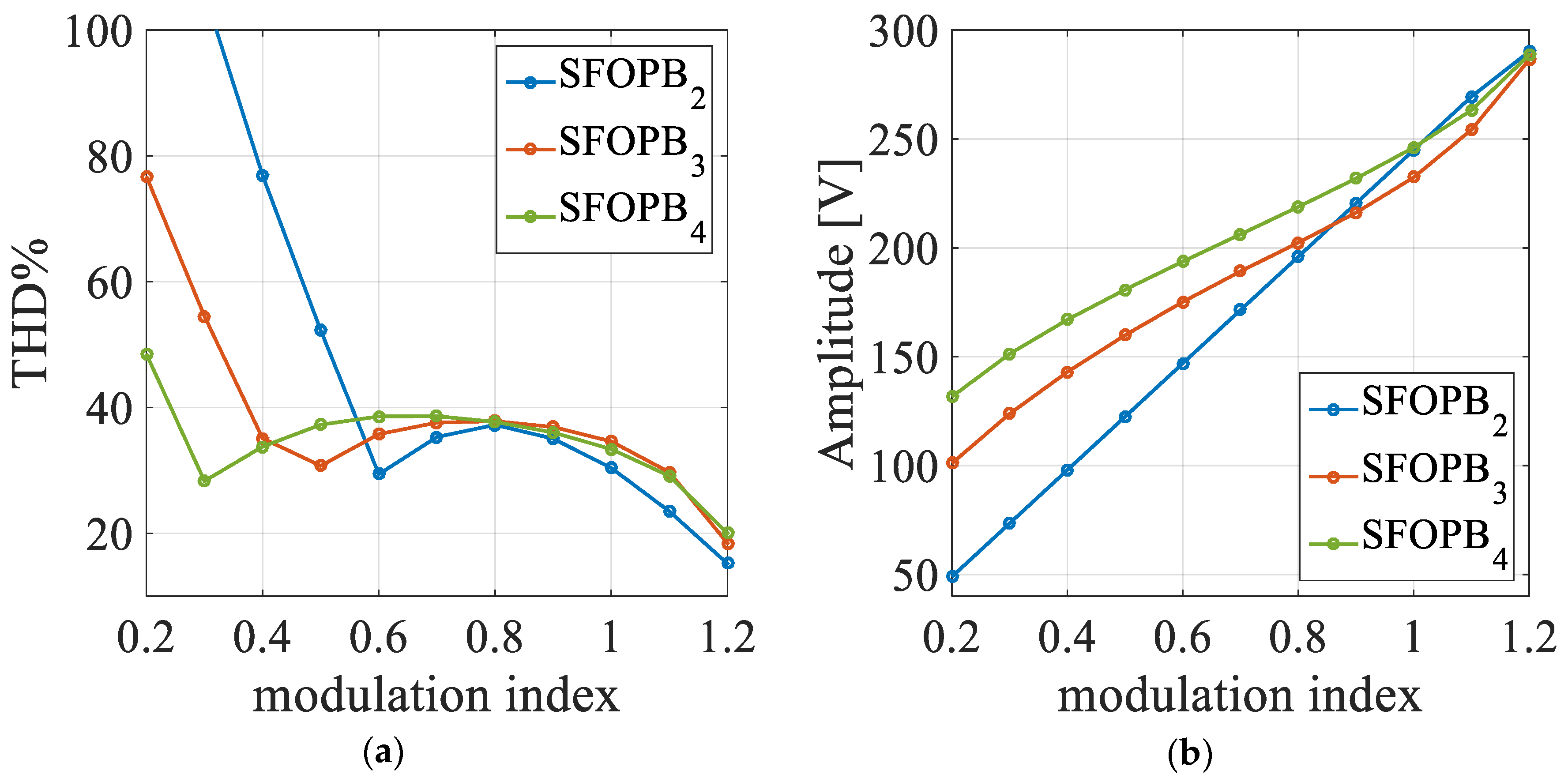
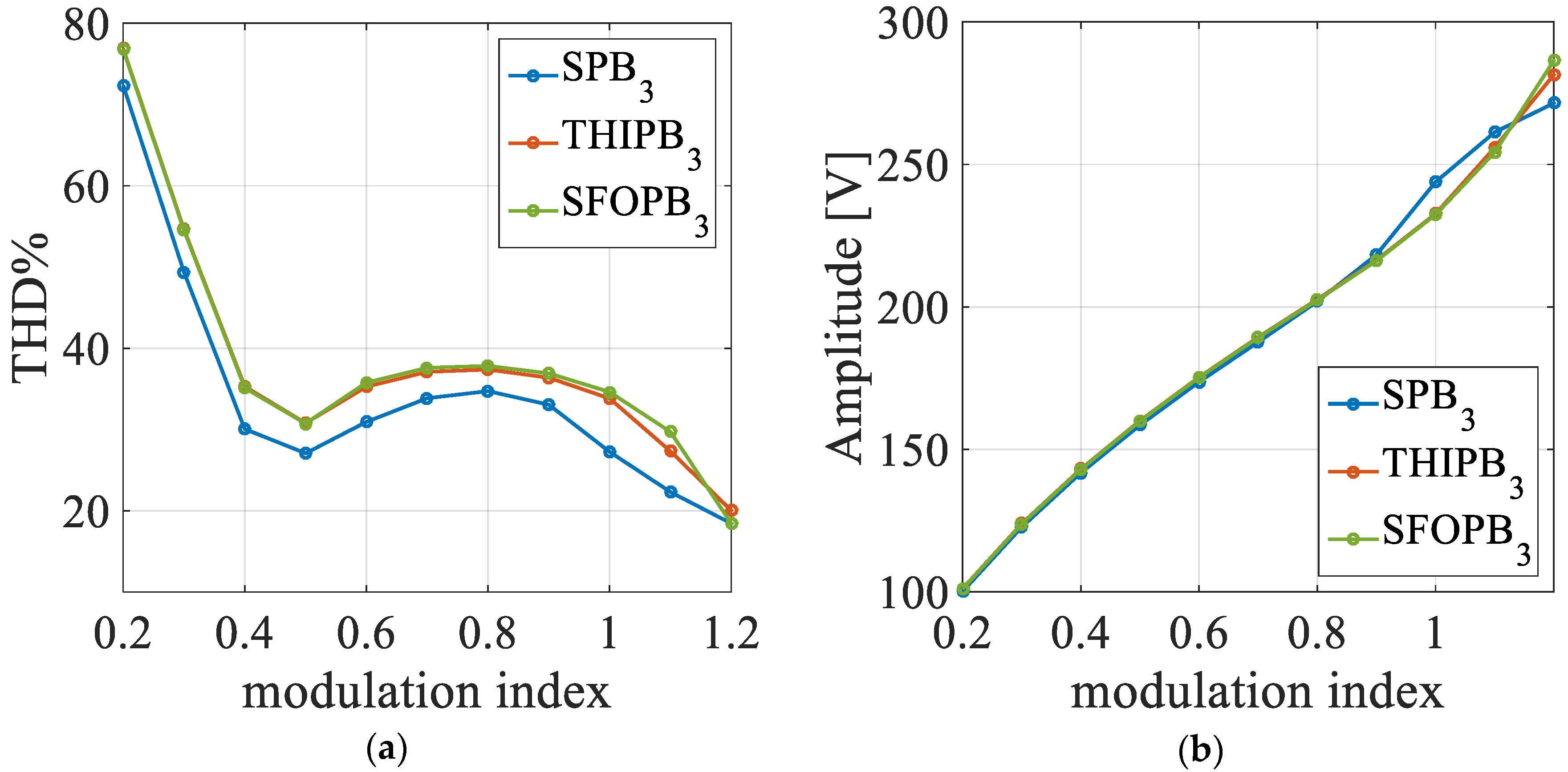
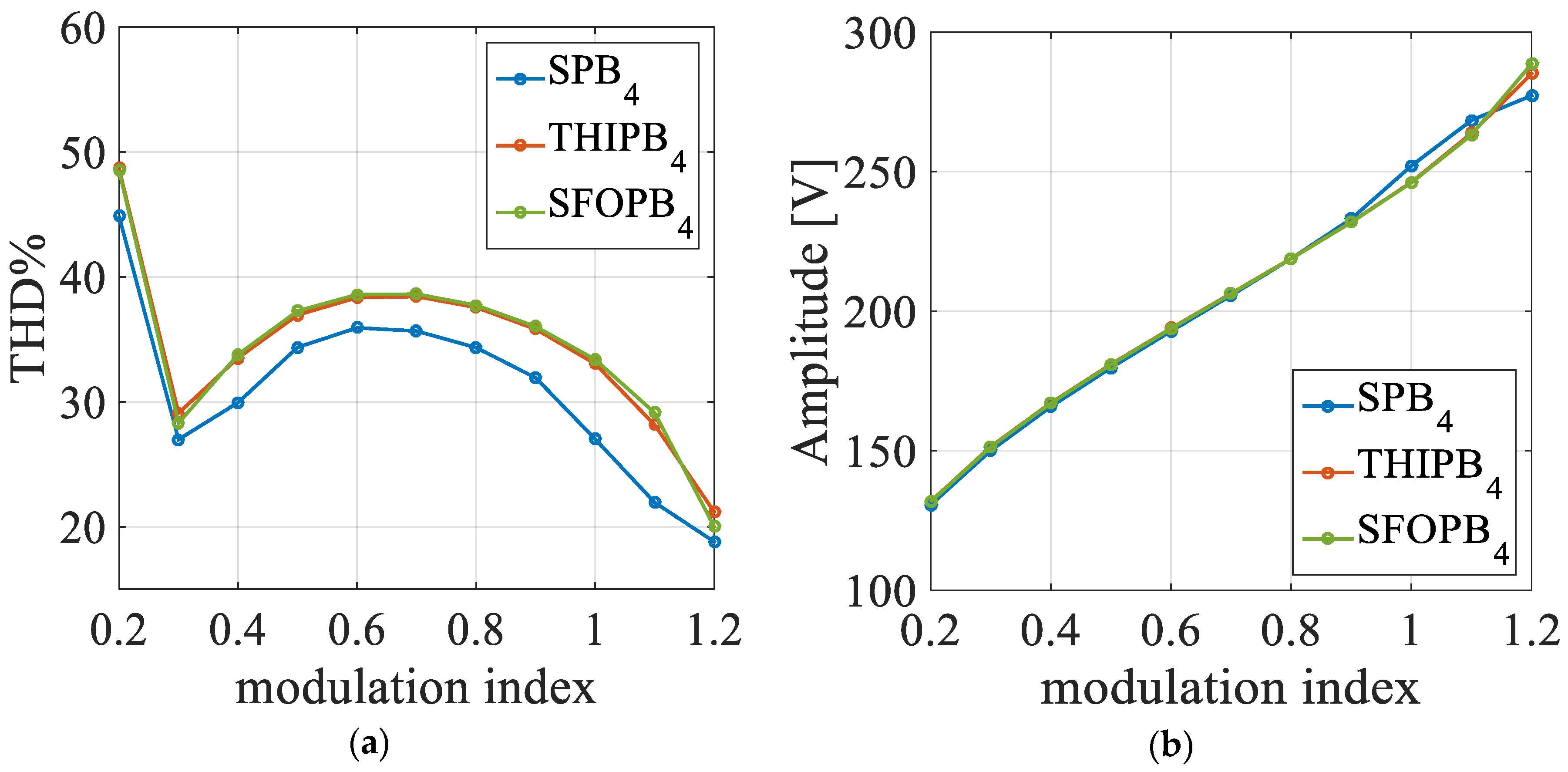
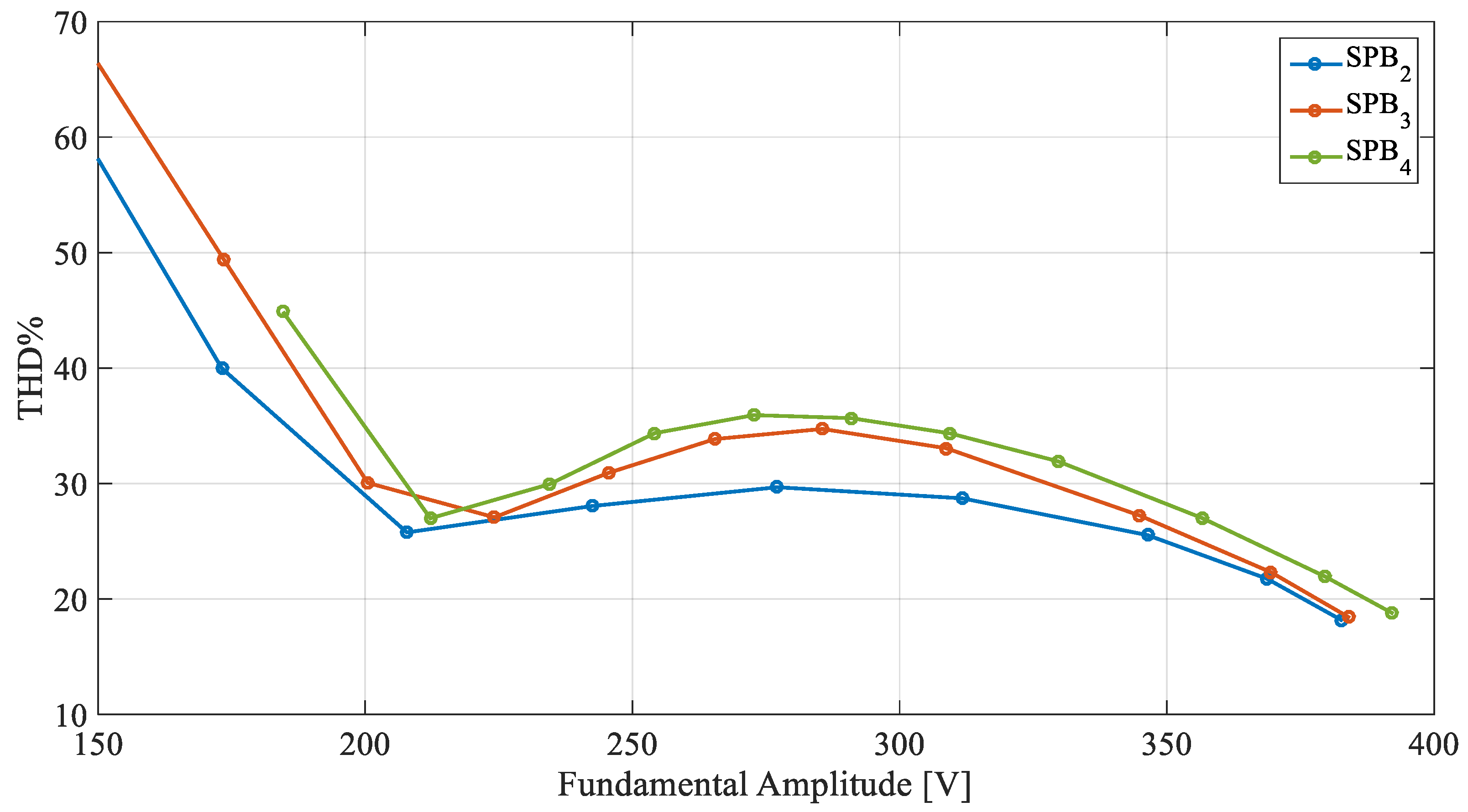
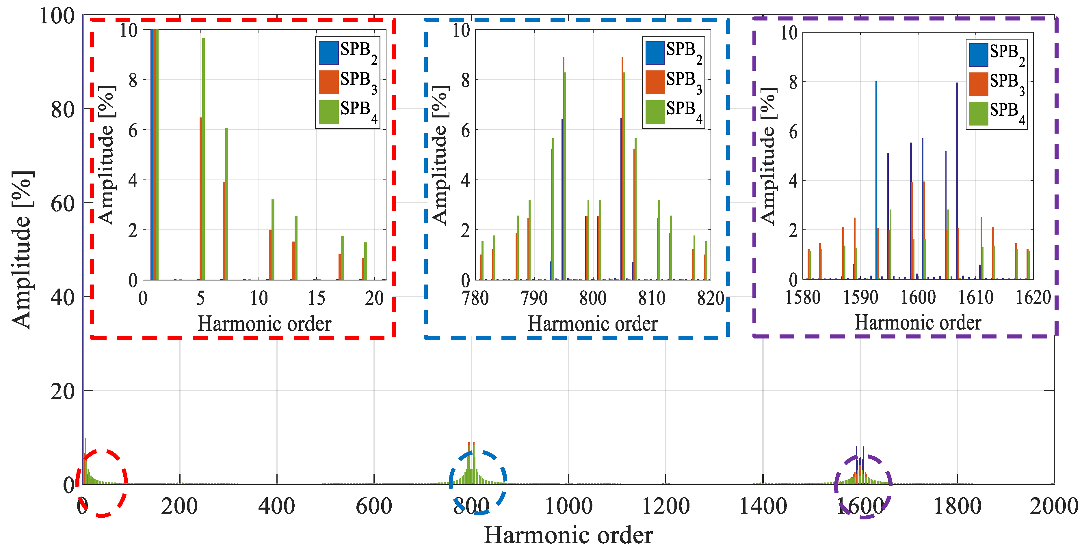
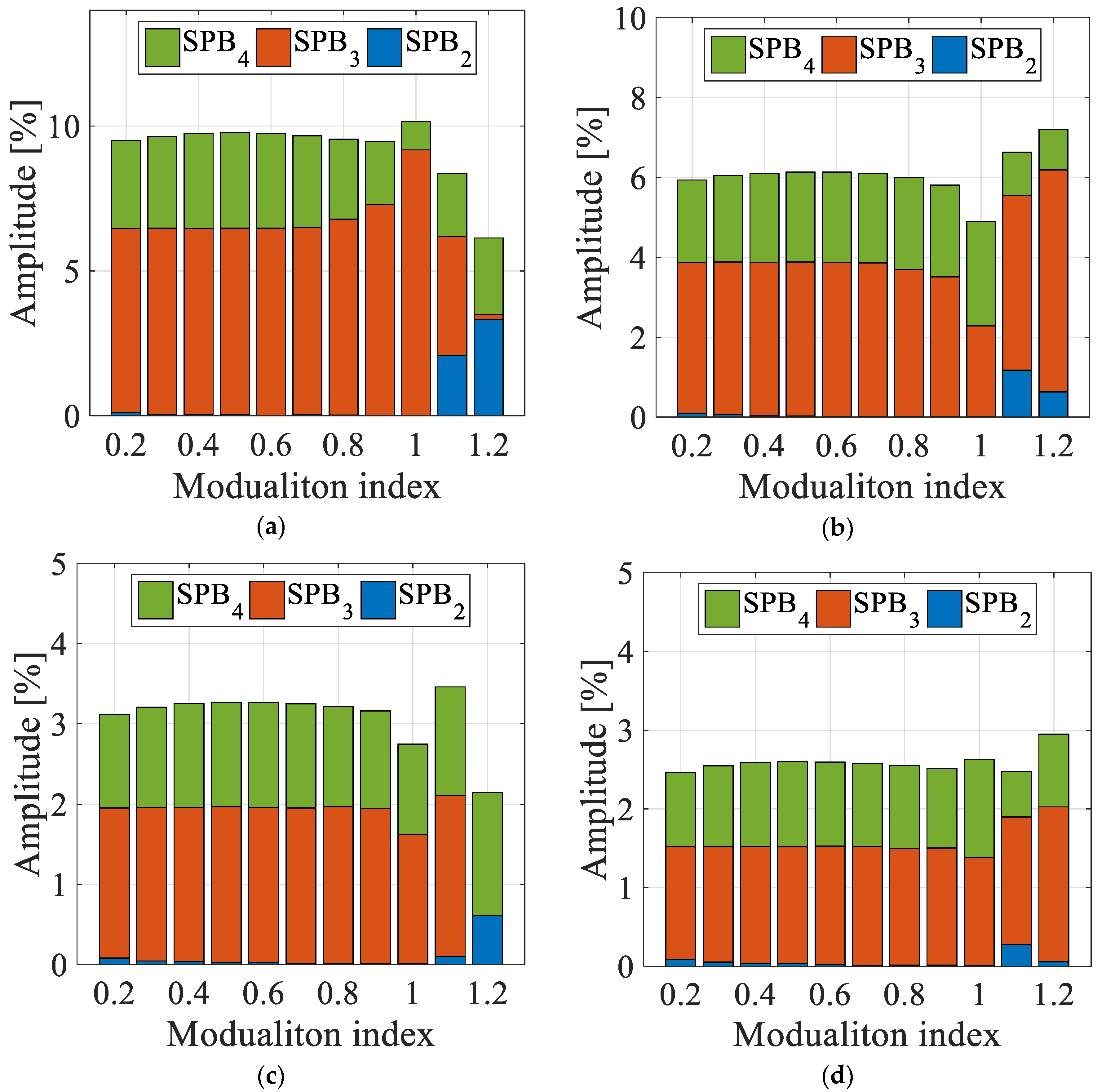
4.1. Single-Phase Multilevel Inverters

For the simulation analysis, a single-phase, five-level, Cascaded H-Bridge Multilevel Inverter (CHBMI) has been simulated, whose parameters are reported in Table 1.
The computed THD% values as function of M for the phase voltage are plotted in Figure 12a–d. It can be noticed that the THD% obtained for the PD (see Figure 12a), POD (see Figure 12b) and APOD (see Figure 12c), for different values of the reference voltage, are similar to each other and almost independent from the considered periodic B-Spline function. Only light differences can be detected, especially for low modulation indexes. Nevertheless, as shown in Figure 12d, significant differences in terms of THD% can be detected between the B-Spline functions by adopting the PS as carrier signal. In particular, for M in the range of [0.2 0.6], PB3 and PB4 present a lower value of THD% with respect to the PB2, which represents the traditional triangular reference waveform. Therefore, this fact leads to a relevant advantage on the adoption of B-Spline functions, especially for variable-speed electrical drives, such as in automotive applications.
In addition, the comparison between the trends of the fundamental amplitude (peak value) of PB2, PB3, and PB4 as function of M obtained with PD, POD, APOD, and PS are plotted in Figure 13a–d), respectively. It can be noticed that the trends obtained with PB3 and PB4 are not linear. Furthermore, the fundamental harmonic amplitudes obtained for PD (see Figure 13a), POD (see Figure 13b) and APOD (see Figure 13c) present similar values between the considered periodic B-Spline functions. Nevertheless, the adoption of the PS technique (see Figure 13d) contributes to an evident boost effect on the fundamental amplitude with PB3 and PB4 and this effect is higher for lower values of the modulation index.
This boost effect on the fundamental amplitude, due to the lower value of the intersection points, explains the lower values of the THD% obtained from Equation (1). Thus, by adopting the B-Spline functions as carrier signals, the five-level voltage waveform appears for lower values of M with respect to the triangular carrier signal. In fact, the modulation techniques with PB3 employs five-levels in the output phase voltage from M = 0.37, whereas the modulation techniques with PB4 as carrier signal employ the five levels from M = 0.26.
Figure 14 and Figure 15 show the voltage trends of PB3 with M = 0.4 and PB4 with M = 0.3. As previously mentioned, the comparison between these two figures demonstrates the so-called “boost effect” introduced by the B-Spline function.
Furthermore, Figure 16 shows the comparison between the THD% values, obtained with the PS technique and PB2, PB3, and PB4 as carrier signals, as function of the fundamental amplitude. Generally, it should be noted that, for an equal value of the fundamental amplitude, the lowest THD% is detected with PB2, except for the range [120 V 140 V] of the fundamental amplitude, in which similar values of THD% are detected.

4.2. Three-Phase Multilevel Inverters

The comparison of both the THD% and the fundamental amplitude of the line voltages as function of M for the SPB2, SPB3, and SPB4 modulation techniques with sinusoidal reference are plotted in Figure 17. It can be noticed that the SPB4 allows the obtainment of lower THD% values for modulation indexes less than 0.4 and higher fundamental amplitude values in the same range. For M in the range between 0.6 and 1, the traditional SPWM technique presents lower values of the THD%, whereas in the over modulation region the THD% presents similar values between all the techniques taken into account.
Similar results in terms of THD% values and fundamental line voltage amplitude are obtained for the SFO and THI modulation techniques, as shown in Figure 18 and Figure 19. More in detail, lower values of THD% are obtained with traditional triangular carrier signal (PB2) for M between 0.6 to 1.2, whereas the fundamental amplitude presents a boost effect for M in the ranges between the values 0.2–1 and 0.2–0.9 for PB4 and PB3, respectively. Similar values of the modulation techniques are detected in the over modulation region.
In order to determine the benefits provided by the THI and SFO reference signals with respect to the sinusoidal one, the THD% and fundamental amplitude trends have been compared with PB3 and PB4 as carrier signals, as shown in Figure 20 and Figure 21, respectively. In both cases, lower values of the THD% are obtained with the sinusoidal reference signal, which is, therefore, the best solution in terms of reference signal.
As well as for the single-phase case, it is interesting to compare the THD% values as a function of the fundamental amplitude, as shown in Figure 22, highlighting the fact that, for low values of the fundamental amplitude, the lowest THD% values are obtained with SPB2, except for values of fundamental amplitude around 220 V, where similar values of THD% between SPB2, SPB3, and SPB4 are detected.
In order to perform a detailed comparison in terms of harmonic content, the Fast Fourier Transform (FFT) is applied to the output voltage of the inverter with the parameters reported in Table 2 (which summarizes the values of M and THD% corresponding to 220 V of the fundamental amplitude for PB2, PB3, and PB4), obtaining the results shown in Figure 23, which depicts the comparison of the harmonic spectra among the SPB2 (blue bars), SPB3 (red bars), and SPB4 (green bars).
The harmonic spectra are comparable throughout the proposed modulation techniques. More in detail, at around four-times of the switching frequency, SPB3 and SPB4 present a pair of predominant side-band harmonics and other components, whose overall contribution is higher with respect to SPB2. Moreover, at eight-times of the switching frequency, a relevant reduction is detected for the SPB3 and SPB4 components if compared with the SPB2 harmonic components. Nevertheless, low-order harmonic components are detected in the harmonic spectra of both SPB3 and SPB4. However, the output line voltages from the inverter, corresponding to the supply voltages of a three-phase motor in case of electrical drive applications, are not affected by the low-order harmonics that are multiple of three.
Figure 24 shows the comparison between the fifth (a), seventh (b), 11th, (c) and 13th (d) order harmonics as function of M, obtained with SPB2 (blue bars), SPB3 (red bars), and SPB4 (green bars). As previously mentioned, low-order harmonics can be observed for each values of the modulation index.
In conclusion, the simulation results have demonstrated that the highest values of THD% have been obtained for modulation techniques with PB3 and PB4 as carrier signals, detecting low order harmonic components in the harmonic spectra.

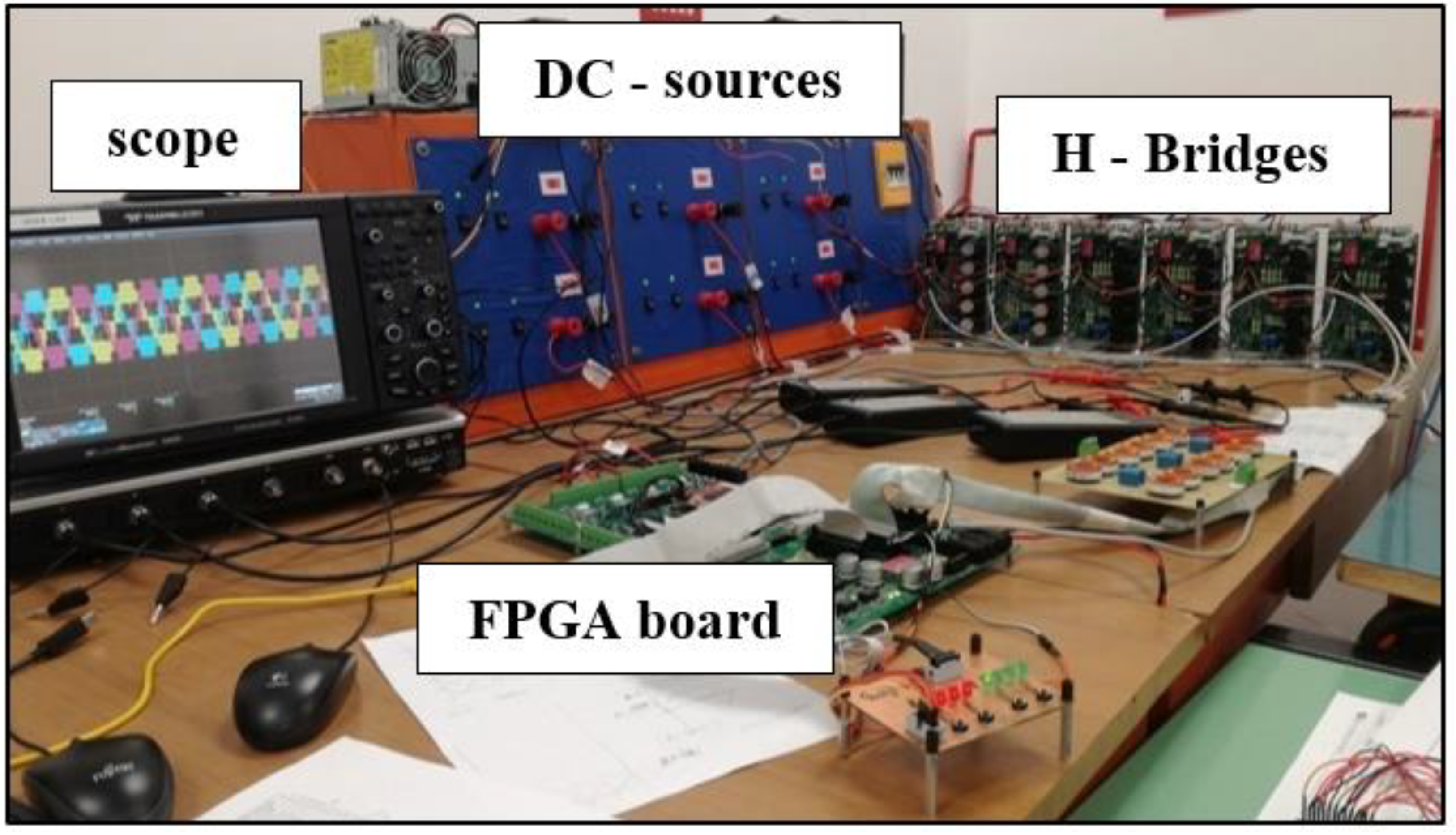
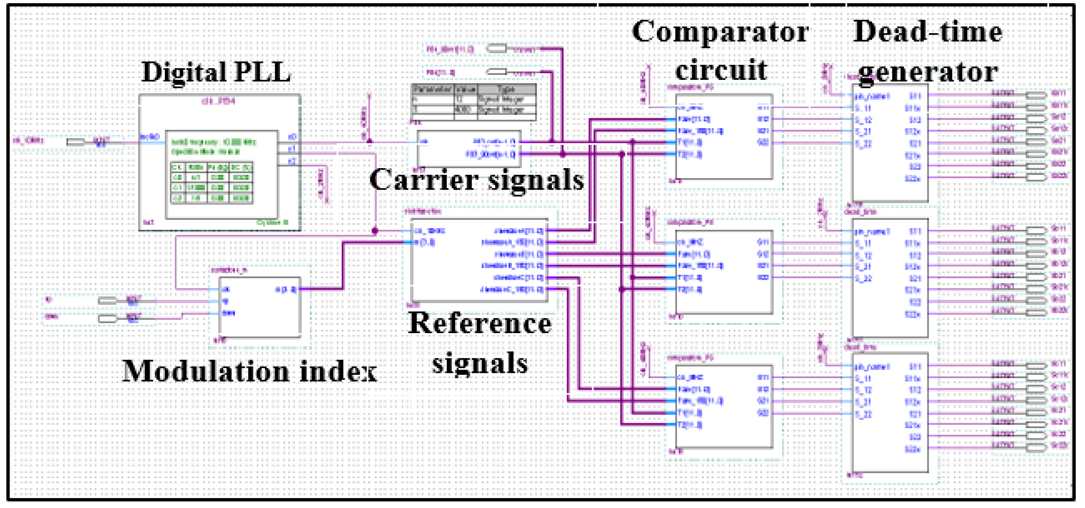
5. Test Bench Equipment and FPGA Algorithm Design

This Section provides a brief description of the test bench assembled in order to carry out the experimental results reported in Section 5. Figure 25 shows a photograph of the test bench, which is mainly composed by the following elements:
A five-level three-phase power MOSFET-based Cascaded H-Bridge;
Six independent DC sources, each one with a rated voltage equal to 12 V;
A control board, based on a prototype of Field Programmable Gate Array (FPGA) (ALTERA, DigiPowers.r.l, model Cyclone III);
A scope (LeCroyWaveRunner 6Zi Teledyne), which is adopted in order to monitor and acquire in real-time the waveforms of voltage and current;
Figure 26 shows the block diagram of the control algorithm implemented in the QuartusII® (Intel Corporationcity, Santa Clara, CA, USA) environment. This scheme is mainly composed by a digital PLL (Phase Locked Loop), a carrier/reference signals generator, a modulation index block, a comparator and a dead-time generator.
The digital PLL allows the generation of the clock signals for each sub-circuit of the system from an external clock signal at a frequency equal to 10 MHz. The modulation index and the reference signals blocks generate the three-phase sinusoidal reference with a fixed amplitude. The sinusoidal reference signals have been sampled with a sample number equal to 200. Thus, these blocks need a clock reference with a frequency equal to 10 kHz in order to obtain a fundamental frequency of 50 Hz.
The generation of PB3 and PB4 is achieved by means of the carrier signal block, whereas the comparator circuit and the dead-time generator blocks allow generating the gate signals and the dead time equal to 400 ns to control the converter through a comparison between the reference signal and carrier signal with a frequency at 40 MHz.

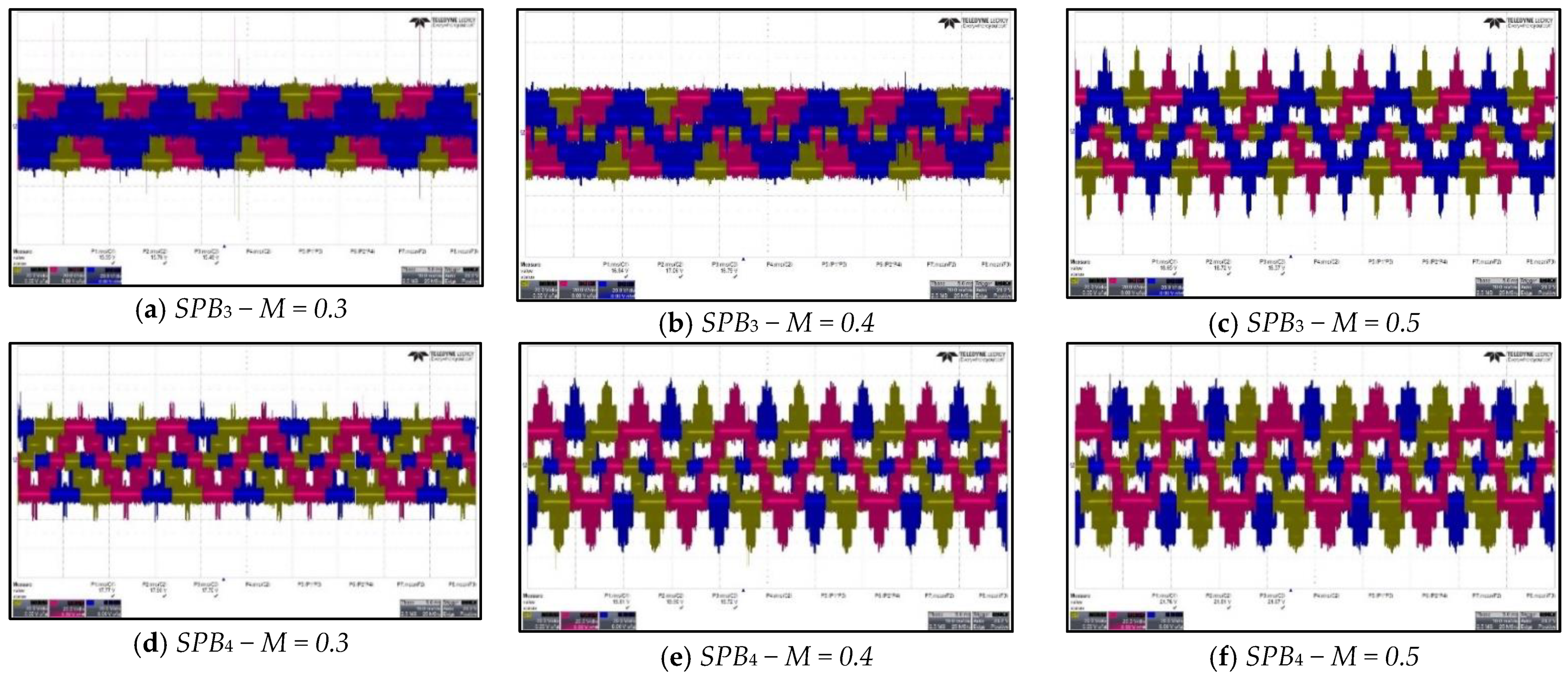
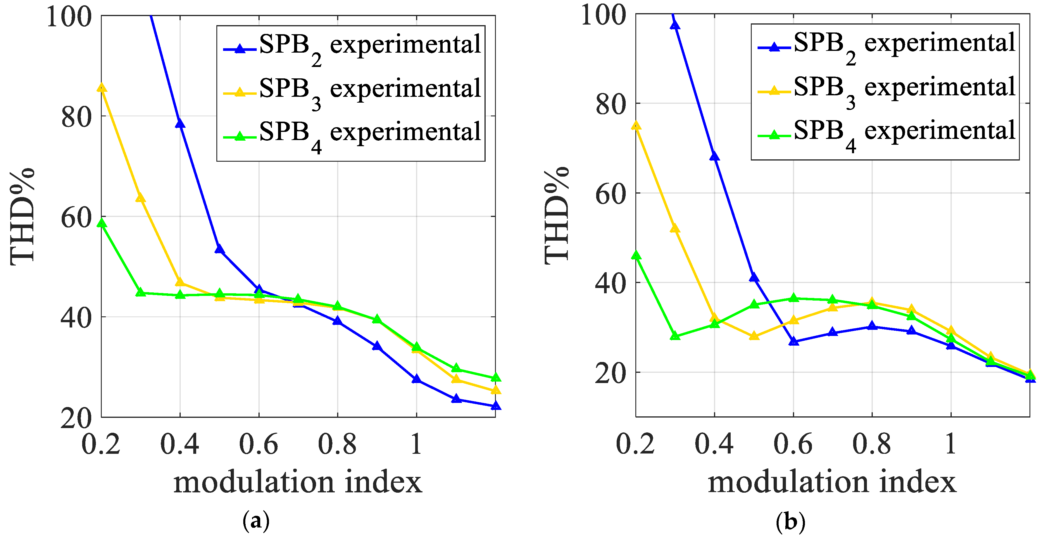
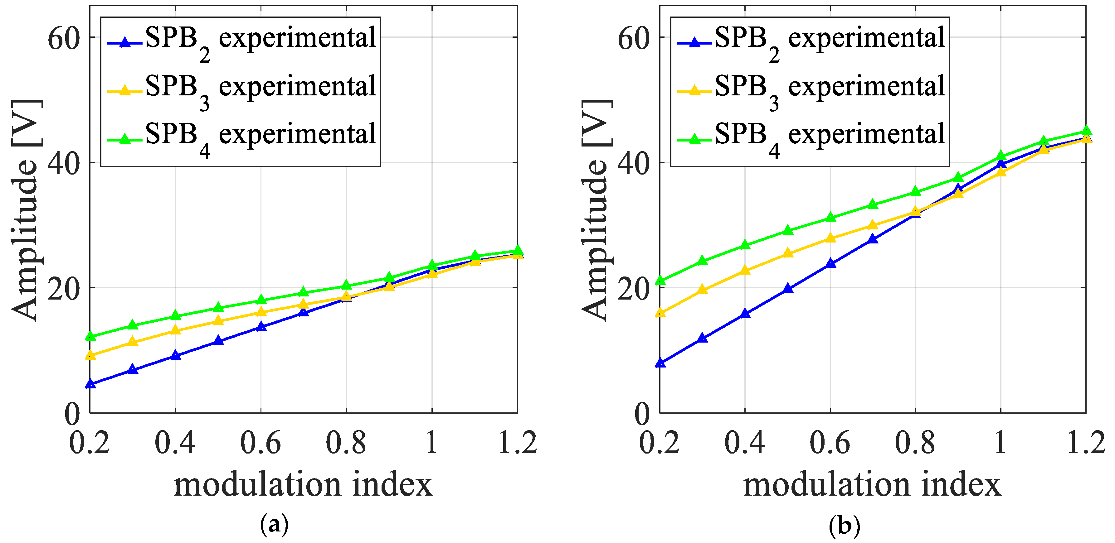
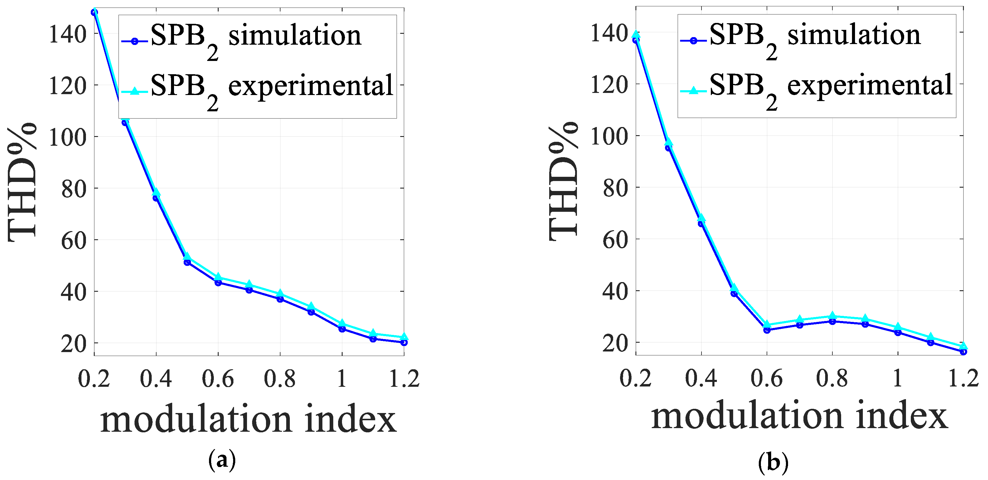
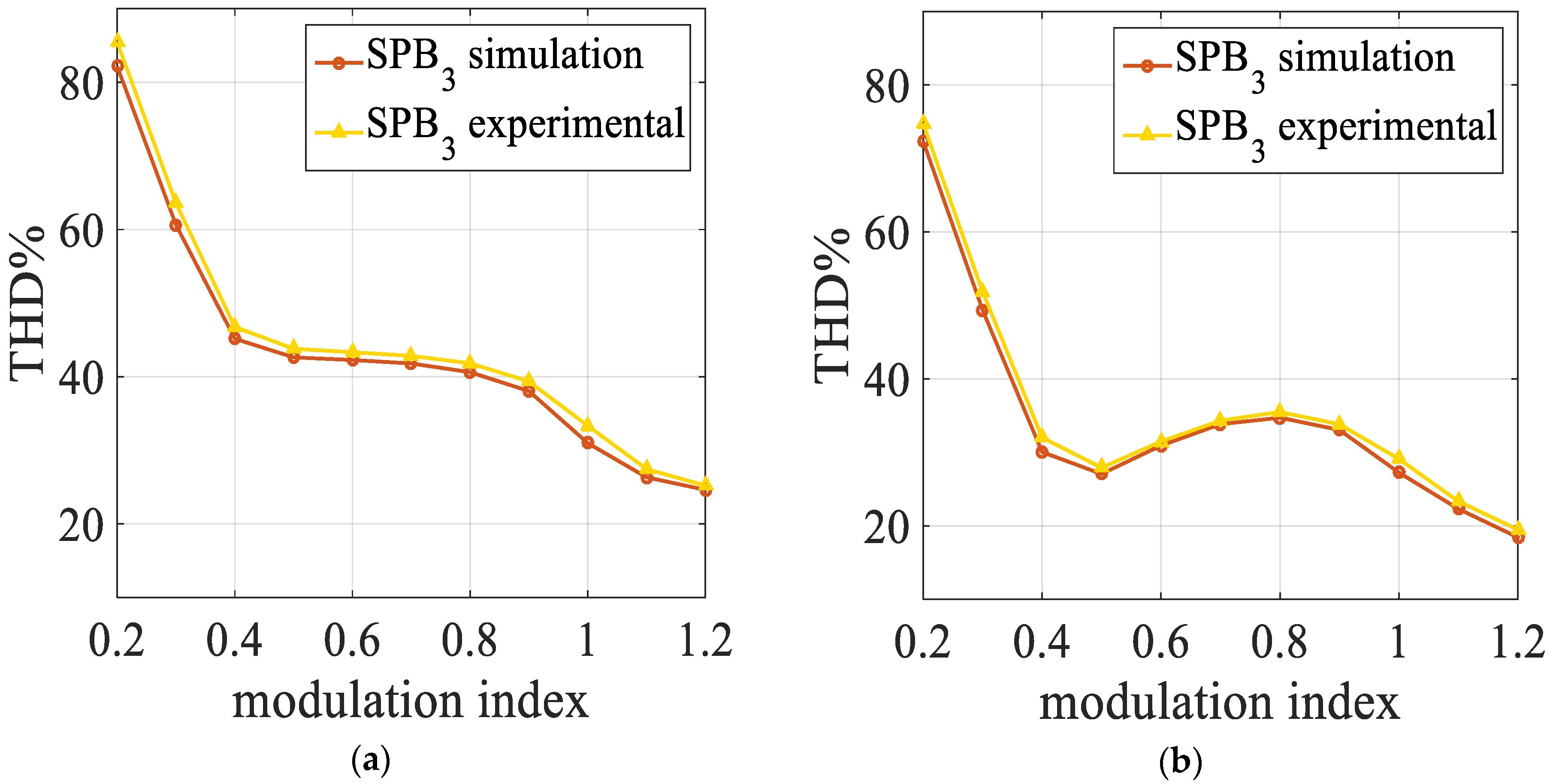
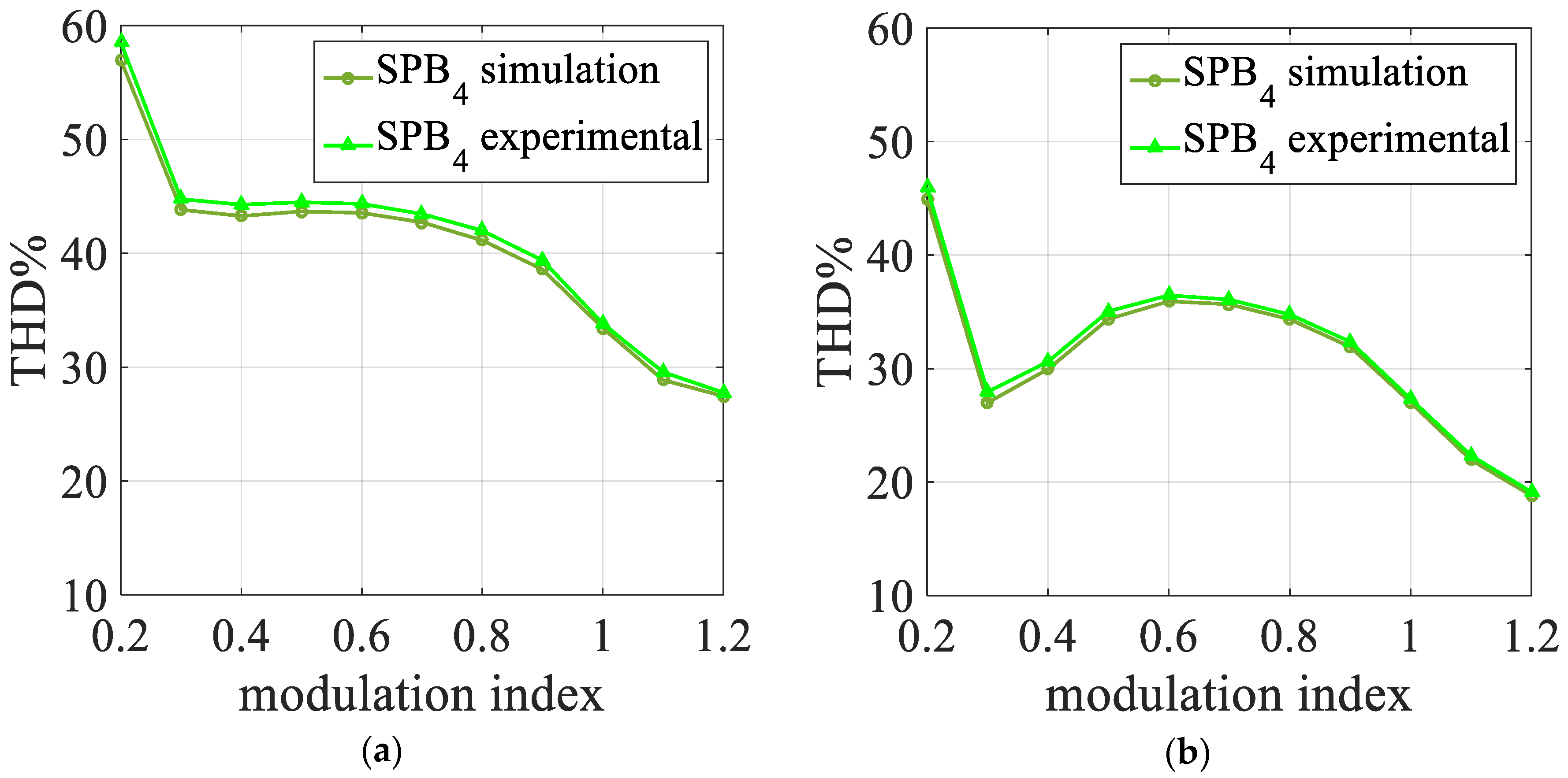
6. Experimental Results and Discussion

The objective of this section is to validate the simulation results described in Section 4 through experimental tests. As mentioned in Section 4, the simulation results for the single-phase case has determined that the most suitable modulation scheme applied to multilevel inverters is the Sinusoidal Phase-Shifted. From this statement, a comparison between simulation and experimental results are reported only for the three-phase case with the SPS technique adopting PB3 and PB4, due to the fact that the single-phase cases are not considered of interest in the proposed work.
By means of the described test bench and control algorithm, the techniques proposed in Section 3 have been experimentally implemented and Figure 27a–f shows the trend of the output line voltage with M ranging from 0.3 to 0.5 for SPB3 and SPB4. It appears evident that these experimental trends present the same behavior of those determined by means of the simulation analysis. In particular, by adopting SPB4 as carrier signal, a five-level voltage for low values of the M is obtained. This phenomenon is due to the lower point of intersection between the carrier signals and it explains the boost effect on the fundamental amplitude. In order to compare the overall harmonic components, the voltage waveforms have been acquired for different values of the modulation index with the parameters reported in Table 3.
Figure 28 shows the computed THD% values of SPB2 (blue curve), SPB3 (yellow curve), and SPB4 (green curve) of the phase voltage (Figure 28a) and line voltage (Figure 28b).
Moreover, the comparison between the computed THD% values confirm the results discussed in Section 4. In particular, the lowest values of the THD% are obtained with PB2 as carrier signals and the boost effect is clearly displayed in the experimental fundamental amplitude trend, as shown in Figure 29.
In any case, as mentioned in Section 4, the output line voltages from the inverter, corresponding to the supply voltages of a three-phase motor in case of electrical drive applications, are not affected by the low-order harmonics that are multiple of three.
Finally, the comparability between the simulation and experimental results in terms of THD% can be clearly visualized for SPB2, SPB3, and SPB4 in Figure 30, Figure 31, and Figure 32, respectively.
Figure 33 shows the screenshot of the phase voltage for different values of the modulation index from 0.2 to 1.0 and low order harmonics spectra with PB4 as carrier signals.

7. Conclusions

This paper has presented an experimental investigation on the adoption of innovative B-Spline-based modulation schemes applied to multilevel Voltage Source Inverters. The Simulation results carried out through the Matlab/Simulink environment are in accordance with the experimental tests, highlighting the fact that the B-Spline functions for multilevel inverters applied, for example, in the field of electrical drives, could bring benefits in terms of increasing the multilevel operation of the converter, but also drawbacks in terms of the presence of some low-order harmonic components in the spectra of the output voltages of the CHBMI.

Author Contributions

Conceptualization, G.S., F.V., and M.C.; methodology, R.M.; software, G.S.; validation, G.S.; writing—review and editing, F.P., V.C., G.S., F.V., and M.C.; supervision, G.A. and M.T.

Funding

This research received no external funding. This work was financially supported by MIUR–Ministero dell’Istruzione dell’Università e della Ricerca (Italian Ministry of Education, University and Research) and by SDESLab (Sustainable Development and Energy Saving Laboratory) and LEAP (Laboratory of Electrical APplications) of the University of Palermo.

Conflicts of Interest

The authors declare no conflict of interest.

References

  1. De Almeida, A.T.; Ferreira, F.J.T.E.; Quintino, A. Technical and economical considerations on super high-efficiency three-phase motors. In Proceedings of the 48th IEEE Industrial & Commercial Power Systems Conference, Louisville, KY, USA, 20–24 May 2012; pp. 1–13. [Google Scholar] [CrossRef]
  2. Ferreira, F.J.T.E.; de Almeida, A.T. Reducing Energy Costs in Electric-Motor-Driven Systems: Savings Through Output Power Reduction and Energy Regeneration. IEEE Ind. Appl. Mag. 2018, 24, 84–97. [Google Scholar] [CrossRef]
  3. De Almeida, P.; Fonseca, F.; Ferreira, F.; Guisse, J.; Blaise, E.; Clair, A.; Diop, A.; Previ, A.; Dominioni, M.; Di Pillo, S.; et al. Improving the Penetration of Energy Efficient Motors and Drives; Technical Report 4.1031/Z96-044; SAVE II Programme; Directorate General of Energy, European Commission: Brussels, Belgium, 2000; Available online: http://publica.fraunhofer.de/dokumente/n-6399.html (accessed on 20 November 2019).
  4. Ferreira, F.; Baoming, G.; de Almeida, A.T. Reliability and operation of high-efficiency induction motors. In Proceedings of the 51st IEEE Industrial & Commercial Power Systems Technical Conf. (I&CPS’2015), Calgary, AB, Canada, 6–8 May 2015; pp. 1–13. [Google Scholar]
  5. Caruso, M.; Di Tommaso, A.O.; Miceli, R.; Nevoloso, C.; Spataro, C.; Viola, F. Characterization of the parameters of interior permanent magnet synchronous motors for a loss model algorithm. Meas. J. Int. Meas.Confed. 2017, 106, 196–202. [Google Scholar] [CrossRef]
  6. Kouro, S.; Malinowski, M.; Gopakumar, K.; Pou, L.; Franquello, L.G.; Wu, B.; Rodriguez, J.; Perez, M.A.; Leon, J.I. Recent Advances and Industrial Applications of Multilevel Converters. IEEE Trans. Ind. Electron. 2010, 57, 2553–2580. [Google Scholar] [CrossRef]
  7. Rodriguez, J.; Franquelo, L.G.; Kouro, S.; Leon, J.I.; Portillo, C.; Prats, M.A.M.; Perez, M.A. Multilevel Converters: An Enabling Technology for High-Power Applications. Proc. IEEE 2009, 97, 1786–1817. [Google Scholar] [CrossRef]
  8. Naouar, M.W.; Monmasson, E.; Naassani, A.A.; Slama-Belkhodja, I.; Patin, N. FPGA-Based Current Controllers for AC Machine Drives—A Review. IEEE Trans. Ind. Electron. 2007, 54, 1907–1925. [Google Scholar] [CrossRef]
  9. Viola, F. Experimental evaluation of the performance of a three-phase five-level cascaded h-bridge inverter by means FPGA-based control board for grid connected applications. Energies 2018, 11, 3298. [Google Scholar] [CrossRef]
  10. De, S.; Banerjee, D.; Kumar, K.S.; Gopakumar, K.; Ramchand, R.; Patel, C. Multilevel inverters for low-power application. IET Power Electron. 2011, 4, 384–392. [Google Scholar] [CrossRef]
  11. Ala, G.; Caruso, M.; Miceli, R.; Pellitteri, F.; Schettino, G.; Trapanese, M.; Viola, F. Experimental investigation on the performances of a multilevel inverter using a field programmable gate array-based control system. Energies 2019, 12, 1016. [Google Scholar] [CrossRef]
  12. Schettino, G.; Benanti, S.; Buccella, C.; Caruso, M.; Castiglia, V.; Cecati, C.; Di Tommaso, A.O.; Miceli, R.; Romano, P.; Viola, F. Simulation and experimental validation of multicarrier PWM techniques for three-phase five-level cascaded H-bridge with FPGA controller. Int. J. Renew. Energy Res. 2017, 7, 1383–1394. [Google Scholar]
  13. Miceli, R.; Schettino, G.; Viola, F. A novel computational approach for harmonic mitigation in PV systems with single-phase five-level CHBMI. Energies 2018, 11, 2100. [Google Scholar] [CrossRef]
  14. Marquez, A.; Leon, J.I.; Vazquez, S.; Portillo, R.; Franquello, L.G.; Freire, E.; Kouro, S. Variable-Angle Phase-Shifted PWM for Multilevel Three-Cell Cascaded H-Bridge Converters. IEEE Trans. Ind. Electron. 2017, 64, 3619–3628. [Google Scholar] [CrossRef]
  15. Grigoletto, F.B.; Pinheiro, H. Generalised pulse width modulation approach for DC capacitor voltage balancing in diode-clamped multilevel converters. IET Power Electron. 2011, 4, 89–100. [Google Scholar] [CrossRef]
  16. Holmes, G.; Lipo, T.A. Pulse Width Modulaiton for Power Converters: Principle and Practice; IEEE Press: Piscataway, NJ, USA, 2003. [Google Scholar]
  17. Wells, J.R.; Geng, X.; Chapman, P.L.; Krein, P.T.; Nee, B.M. Modulation-Based Harmonic Elimination. IEEE Trans. Power Electron. 2007, 22, 336–340. [Google Scholar] [CrossRef]
  18. De Boor, C. Approximation Theory; American Mathematical Society: New Orleans, LA, USA, 1986; Volume 36. [Google Scholar]
  19. De Boor, C. A Practical Guide to Splines; Springer: New York, NY, USA, 2001; ISBN 0387953663. [Google Scholar]
  20. Saleh, S.A.; Rahman, M.A. Development and Experimental Testing of a Single-Phase B-Spline-Based SPWM Inverter. In Proceedings of the 2006 IEEE International Symposium on Industrial Electronics, Montreal, QC, Canada, 9–13 July 2006; pp. 815–819. [Google Scholar]
  21. Saleh, S.A.; Rahman, M.A. Discrete time-based model of the sinusoidal pulse width modulation technique. In Proceedings of the 31st Annual Conference of IEEE Industrial Electronics Society, Raleigh, NC, USA, 6–10 November 2005; p. 6. [Google Scholar]
  22. Saleh, S.A.; Rahmen, M.A. Experimental testing of a novel control for inverter-fed three-phase induction motor. In Proceedings of the 2006 IEEE Power Engineering Society General Meeting, Montreal, QC, Canada, 18–22 June 2006; p. 5. [Google Scholar] [CrossRef]
  23. Genduso, R.; Miceli, R.; Rando, C. Algebraic real-time algorithm for B-Spline sinusoidal pulse width modulation in three phase voltage source inverters. In Proceedings of the 2008 IEEE International Symposium on Industrial Electronics, Cambridge, UK, 30 June–2 July 2008; pp. 353–358. [Google Scholar]
  24. Genduso, R.; Miceli, R.; Rando, C. Implementation and experimental validation of a real-time PWM algorithm based on B-Spline carriers for three phase voltage source inverters. In Proceedings of the 2009 IEEE International Symposium on Industrial Electronics, Seoul, Korea, 5 June–8 July 2009; pp. 1829–1834. [Google Scholar]
  25. Di Tommaso, O.; Genduso, F.; Miceli, R.; Raciti, A. A reexamination of voltage distortion for classical carrier-based vs B-Spline modulation of three-phase Voltage Sources Inverters. In Proceedings of the 2015 IEEE 24th International Symposium on Industrial Electronics (ISIE), Buzios, Brazil, 3–5 June 2015; pp. 986–991. [Google Scholar]
  26. Schettino, G.; Castiglia, V.; Genduso, F.; Livreri, P.; Miceli, R.; Romano, P.; Viola, F. Simulation of a single-phase five-level cascaded H-Bridge inverter with multicarrier SPWM B-Spline based modulation techniques. In Proceedings of the 2017 Twelfth International Conference on Ecological Vehicles and Renewable Energies (EVER), Monte Carlo, Monaco, 11–13 April 2017; pp. 1–6. [Google Scholar]
  27. Castiglia, V.; Livreri, P.; Miceli, R.; Raciti, A.; Schettino, G.; Viola, F. Performances of a three-phase five-level cascaded H-bridge inverter with phase shifted B-spline based modulation techniques. In Proceedings of the 2017 IEEE 6th International Conference on Renewable Energy Research and Applications (ICRERA), San Diego, CA, USA, 5–8 November 2017; pp. 1192–1197. [Google Scholar]
  28. Cohen, A.; Daubechies, I.; Vial, P. Multiresolution analysis, wavelets and fast algorithms on an interval. Appl. Comput. Harmon. Anal. 1993, 1, 100–115. [Google Scholar]
  29. Cohen, A.; Daubechies, I.; Vial, P. Wavelets on the interval and fast wavelet transform. Appl. Comput. Harmon. Anal. 1993, 1, 54–81. [Google Scholar] [CrossRef]
  30. Ala, G.; Francomano, E.; Viola, F. A wavelet operator on the interval in solving Maxwell’s equations. Prog. Electromagn. Res. Lett. 2011, 27, 133–140. [Google Scholar] [CrossRef]
  31. Barmada, S.; Musolino, A.; Raugi, M. Wavelet-based time-domain solution of multiconductor transmission lines with skin and proximity effect. IEEE Trans. Electromagn. Compat. 2005, 47, 774–780. [Google Scholar] [CrossRef]
  32. Barmada, S.; Musolino, A.; Raugi, M. Analysis of Integrated circuit systems by an innovative wavelet-based scattering matrix approach. IEEE Trans. Adv. Packag. 2007, 30, 86–96. [Google Scholar] [CrossRef]
  33. Daubechies, I. Ten Lectures on Wavelets; SIAM: Philadelphia, PA, USA, 1992; p. 12. [Google Scholar]
  34. Rubinacci, G.; Tamburrino, A.; Ventre, S.; Villone, S. Interpolating wavelets for the solution of Maxwell equations in the time domain. IEEE Trans. Magn. 1998, 34, 2775–2778. [Google Scholar] [CrossRef]
  35. Carrara, G.; Gardella, S.; Marchesoni, M.; Salutari, R.; Sciuto, G. A new multilevel PWM method: A theoreotical analysis. IEEE Trans. Power Electron. 1992, 7, 497–505. [Google Scholar] [CrossRef]
  36. McGrath, B.P.; Holmes, D.G. Multicarrier PWM strategies for multilevel inverters. IEEE Trans. Ind. Electron. 2002, 49, 858–867. [Google Scholar] [CrossRef]
  37. Balamurugan, C.R.; Natarajan, S.P.; Bensraj, R.; Shanthi, B. A Review on Modulation Strategies of Mulilevel Inverter. Indones. J. Electr. Eng. Comput. Sci. 2016, 3, 681–705. [Google Scholar] [CrossRef]
Figure 1. Cardinal B-Spline functions obtained by means of the convolution procedure: (a) first order; (b) second order; (c) third order; and (d) fourth order.
Energies 12 04521 g001
Figure 2. First order periodic B-spline function, (a) temporal representation of the function and (b) related harmonic spectrum. Sometimes named Haar function.
Energies 12 04521 g002
Figure 3. Second order periodic B-Spline function, (a) temporal representation of the function and (b) related harmonic spectrum.
Energies 12 04521 g003
Figure 4. Third order periodic B-Spline function, (a) temporal representation of the function and (b) related harmonic spectrum.
Energies 12 04521 g004
Figure 5. Fourth order periodic B-Spline function, (a) temporal representation of the function and (b) related harmonic spectrum.
Energies 12 04521 g005
Figure 6. Third order B-spline-based modulation schemes: (a) PD, (b) POD, (c) APOD, and (d) PS.
Energies 12 04521 g006
Figure 7. Fond urth order B-spline-based modulation schemes: (a) PD, (b) POD, (c) APOD, (d) PS.
Energies 12 04521 g007
Figure 8. Comparison between the intersections of PS carrier signals for a five-level converter. In traditional modulation scheme with triangle waveform as carrier signals (PB2) the transition from three to five levels occurs for modulation index equal to 0.5. By using the B-spline functions as carrier signals (PB3 and PB4), this transition is achieved for lower values of the modulation index, equal to 0.37 and 0.26 for PB3 and PB4, respectively.
Energies 12 04521 g008
Figure 9. Modulation schemes with sinusoidal reference, the three different phases are sketched in green, yellow and purple, blue and orange are used for the carriers employing periodic B-spline function: (a) SPB3 and (b) SPB4.
Energies 12 04521 g009
Figure 10. Modulation schemes with Total Harmonic Injection (THI) reference for each phase (green, yellow and purple): (a) SPB3 and (b) SPB4.
Energies 12 04521 g010
Figure 11. Modulation schemes with Switching Frequency Optimal, (SFO) reference for each phase (grren, yellow and purple): (a) SPB3 and (b) SPB4.
Energies 12 04521 g011
Figure 12. THD% comparison between the PB2, PB3, and PB4 for each carrier signal: (a) PD, (b) POD, (c) APOD, and (d) PS.
Energies 12 04521 g012
Figure 13. Fundamental amplitude comparison between the PB2, PB3, and PB4 for each carrier signal: (a) PD, (b) POD, (c) APOD, and (d) PS.
Energies 12 04521 g013
Figure 14. Voltage trend with PB3 as carrier signal and M = 0.4; the five-level voltage waveform appears for lower values of M with respect to the triangular carrier signal.
Energies 12 04521 g014
Figure 15. Voltage trend with PB4 as carrier signal and M = 0.3, the five-level voltage waveform appears for lower values of M with respect to the triangular carrier signal.
Energies 12 04521 g015
Figure 16. Comparison of THD% versus fundamental amplitude among PB2, PB3, and PB4 for PS.
Energies 12 04521 g016
Figure 17. Comparison between the simulation results obtained with the modulation schemes SPB2, SPB3, and SPB4 of: (a) THD% and (b) peak values of fundamental amplitude of the line voltage.
Energies 12 04521 g017
Figure 18. Comparison between the simulation results obtained with the modulation schemes THIPB2, THIPB3, and THIPB4 of: (a) THD% and (b) peak values of fundamental amplitude of the line voltage.
Energies 12 04521 g018
Figure 19. Comparison between the simulation results obtained with the modulation schemes SFOPB2, SFOPB3, and SFOPB4 of: (a) THD% and (b) peak values of fundamental amplitude of the line voltage.
Energies 12 04521 g019
Figure 20. Comparison between the THD% and fundamental amplitude of the line voltage with sinusoidal, THI, and SFO as reference signals and with PB3 as the carrier signal: (a) behavior of THD%; (b) amplitude of fundamental.
Energies 12 04521 g020
Figure 21. Comparison between the THD% and fundamental amplitude of the line voltage with sinusoidal, THI, and SFO as reference signals and with PB4 as carrier signal: (a) behavior of THD%; (b) amplitude of fundamental.
Energies 12 04521 g021
Figure 22. Comparison between the THD% values as function of the fundamental amplitude among SPB2, SPB3, and SPB4.
Energies 12 04521 g022
Figure 23. Comparison between the harmonic spectra referred to the fundamental amplitude of the line voltage for SPB2 (blue bars), SPB3 (red bars), and SPB4 (green bars).
Energies 12 04521 g023
Figure 24. Comparison between the low order harmonics as function of M: (a) fifth order (b) seventh order (c) 11th order, and (d) 13th order harmonics.
Energies 12 04521 g024
Figure 25. Photograph of the test bench.
Energies 12 04521 g025
Figure 26. Block diagram of the control algorithm in the Quartus II environment.
Energies 12 04521 g026
Figure 27. Evolution of the line voltage trend for low modulation index values between SPB3 and SPB4. (a) SPB3 and M = 0.3 realize a three level operation, (b) SPB3 and M = 0.4 realize a three level operation, (c) SPB3 and M = 0.5 realize a five level operation, (d) SPB4 and M = 0.3 realize a three level operation, (e) SPB4 and M = 0.4 realize a five level operation, (f) SPB4 and M = 0.5 realize a three level operation.
Energies 12 04521 g027
Figure 28. Comparison between the experimental THD% obtained with SPB2, SPB3, and SPB4: (a) phase voltage and (b) line voltage.
Energies 12 04521 g028
Figure 29. Comparison between the experimental fundamental amplitude with SPB2, SPB3, and SPB4: (a) phase voltage and (b) line voltage.
Energies 12 04521 g029
Figure 30. Comparison between the simulated and experimental THD% PB2 as carrier signal: (a) phase voltage and (b) line voltage.
Energies 12 04521 g030
Figure 31. Comparison between the simulated and experimental THD% PB3 as carrier signal: (a) phase voltage and (b) line voltage.
Energies 12 04521 g031
Figure 32. Comparison between the simulated and experimental THD% PB4 as carrier signal: (a) phase voltage and (b) line voltage.
Energies 12 04521 g032
Figure 33. Screenshot of the phase voltage and low order harmonics spectra with PB4 as carrier signals for modulation index from 0.3 to 1 (10 V/div and 100 Hz/div). (a) low value of fundamental due to the limited five level operation; (b) limited increase of fundamental; (c) appreciable increase of the fundamental; (d) considerable increase of fundamental; (e) good operation of the fundamental; (f) maximum value of the fundamental.
Energies 12 04521 g033
Table 1. Simulation parameters.
QuantitySymbolValue
Reference frequencyf50 Hz
Switching frequencyfPWM10 kHz
Frequency modulation indexmf200
DC Voltage VDC100 V
Voltage levell
Table 2. Simulation parameters.
QuantitySPB2SPB3SPB4
Modulation index, M0.630.50.3
Fundamental Amplitude (peak value)219 V224 V214 V
THD%26.6%27.1%27%
Table 3. Acquisition parameters.
QuantityValue
Sample frequency25 MHz
Sample number500,000
Acquisition time20 ms

