Mitigating Impulsive Noise for Wavelet-OFDM Powerline Communication


1
Department of Electrical Engineering, National Ilan University, Yilan 26047, Taiwan
2
LitePoint Technology, Ltd., Taipei 11492, Taiwan
*
Author to whom correspondence should be addressed.
Energies 2019, 12(8), 1567; https://0-doi-org.brum.beds.ac.uk/10.3390/en12081567
Submission received: 27 March 2019
/
Revised: 19 April 2019
/
Accepted: 22 April 2019
/
Published: 25 April 2019
Abstract
:Advanced metering infrastructure (AMI) is an important application of smart grid communication technology used for the remote monitoring and control of smart meters. Broadband powerline communication (BB-PLC) systems could perhaps be used for AMI; however, impulsive noise (IN) greatly degrades performance. In addition to the fast Fourier transform (FFT)-based orthogonal frequency-division multiplexing (OFDM), IEEE 1901 specifications have defined the other physical layer called wavelet-based OFDM. Even though many existing studies have reported the IN mitigation algorithms for the FFT-based OFDM system, these approaches may not directly apply to the wavelet-OFDM-based PLC systems. In this paper, we propose a robust receiver for PLC systems based on wavelet-OFDM. The proposed receiver comprises a pre-IN mitigation block, an adaptive inverse discrete wavelet transform, and an iterative IN reconstruction block. The iterative cancellation of strong IN samples leads to a gradual improvement in the quality of the received signal. Instead of using the frequency domain approach, we reduce the inter-dependency of the channel estimation and per-subchannel equalization by using the time domain signal processing. Besides, we apply variable step-size adaptive algorithms to reduce the impact of IN during the training processes for the channel estimator and per-subchannel equalizer. In accordance with IEEE 1901 specifications, we built a simulation environment to evaluate the effectiveness of the proposed method. Simulation results demonstrated that conventional blanking devices fall short in terms of IN mitigation, and that the proposed scheme is able to achieve performance values approaching those obtained in cases without IN.
1. Introduction
With an advanced metering infrastructure (AMI), researchers have shown that broadband powerline communication (BB-PLC) systems are applicable to backhaul communication [1] and service quality estimation [2]. In Korea, a power company has adopted BB-PLC systems for nationwide AMI to serve 22.50 million low-voltage customers until 2020 [2]. For distributed smart grid applications, BB-PLC systems are possible wired technologies to indoor communications between smart meters and photovoltaic inverters [3]. One of the advantages of powerline communication (PLC) technologies is that the powerline infrastructure has already deployed so that installation costs could be reduced. The transmission distance for BB-PLC is up to about 1.5 kilometers, it is more suitable for home area networks [4] (p. 117). Some field trials have been conducted to validate feasibility of using BB-PLC for smart grid applications [5]. It has pointed out that narrowband PLC (NB-PLC) is affected by inverters used in some home appliances. This is mainly because of NB-PLC and inverters are operating on the same frequency band (3–148.5 kHz). However, BB-PLC does not suffer from such problems because of using a broad frequency band (3–30 MHz). In addition, the highest available date rate with NB-PLC, which is around 500 Kb/s, is insufficient for common and future smart grid services. However, PLC was designed for power delivery rather than data transmission; therefore, from the perspective of data transmission, issues associated with PLC channels like impulsive noise (IN), frequency-dependent attenuation, narrowband interference, and time-varying impedance are needed to be addressed [6,7]. The most intractable issue is IN. Due to the short duration and high magnitude properties, IN can be regarded as high-power wideband noise in the frequency domain [8]. In PLC systems based on orthogonal frequency-division multiplexing (OFDM), the noise bucket effect [9] significantly increases in the bit error rate (BER) [10]. BB-PLC schemes with two physical specifications have been proposed by IEEE: fast Fourier transform (FFT) -based OFDM and wavelet-based OFDM [11]. Wavelet-OFDM-based PLC employs an M-band transmultiplexer, which allows the stopband attenuation of subcarriers to exceed 35 dB [12]. Comparing with FFT-based OFDM systems, wavelet-based OFDM systems offer better subchannel isolation. An inverse discrete wavelet transform (IDWT) block is used at the transmitter and a discrete wavelet transform (DWT) block is used at the receiver.
Many IN mitigation schemes have been proposed for FFT-OFDM-based PLC systems. Zhidkov assessed a number of nonlinear IN mitigation techniques, included clipping, nulling, and a mixture of both nulling and clipping approaches [13]. A scheme combining nulling, clipping, and replacement was proposed in Reference [14], and the multipath issue was further considered in Reference [15]. A scheme based on deep clipping was proposed in Reference [16] to enhance the effectiveness of the nonlinear IN mitigation methods described above. Unfortunately, some pre-determined parameters, which tend to vary with the channel conditions, are required for determining the threshold values. In Reference [17], the authors utilized zero carriers to estimate noise power and the IN parameters were extracted to calculate the optimal clipping threshold. However, Yin pointed out that nonlinear devices used to mitigate IN cause intercarrier interference and degrade system performance [18]. Consequently, Zhidkov reported an iterative IN mitigation scheme for OFDM-based digital terrestrial video broadcasting systems [19]. A number of sophisticated multilayer perceptron [20] and deep neural network [21] schemes have been developed to mitigate IN. An iterative receiver for FFT-OFDM-based PLC systems was proposed in Reference [22], which simultaneously considered the channel estimation, channel equalization, and IN mitigation issues in the frequency domain. By iteratively mitigating part of IN samples with stronger amplitude, the quality of channel estimation could be improved gradually. Thus, the quality of the estimation of residual IN samples was gradually improved as well, i.e., the channel estimation and IN mitigation are mutually beneficial. In Reference [23], the authors used a linear precoder at the transmitter and applied overlapped frequency-domain equalizers to mitigate IN for wavelet-OFDM-based PLC systems. The linear precoder, which is implemented by using a Walsh–Hadamard transform, improves the efficiency of the frequency domain equalizer. However, adding the linear precoder to the transmitter does not comply with IEEE 1901 specifications. Moreover, the frequency domain equalizer requires extra FFT and inverse FFT operations.
Although many IN mitigation approaches have been proposed on FFT-based OFDM systems, these existing approaches cannot directly apply to the wavelet-based OFDM. To the best of our knowledge, researchers have largely overlooked the issue of IN mitigation for wavelet-OFDM-based PLC systems. Inspired by the iterative receiver for the FFT-OFDM-based PLC system [22], this paper presents a robust receiver architecture for wavelet-OFDM-based PLC systems to fill this research gap. The receiver comprises a pre-IN mitigation block, an adaptive DWT block, and an iterative IN reconstruction block. The pre-IN mitigation block copes with the stronger portion of the IN to facilitate the training of equalizers and channel estimator. Adaptive per-subchannel equalizers are applied to the conventional DWT block to flatten out the passband of each subchannel, and the IN reconstruction block iteratively estimates the residual IN. Note that to alleviate the impact of IN samples on the training algorithms, we applied a variable step-size adaptive algorithm [24]. Comparing with our previous work [22], the new contributions of this paper are summarized as follows. First, we proposed an adaptive analysis filter bank, comprised of the DWT block and adaptive per-subchannel equalizers, such that the channel is equalized in the time domain for each subchannel. In this way, no additional FFT operation is required to perform equalization in the frequency domain. Note that a wavelet-based OFDM system does not implement guard interval and causes performance degradation in the multipath PLC channels. Thus, the realization of equalizers form wavelet-based OFDM systems is an important issue that needed to be addressed. Second, we decoupled the channel estimation from the per-subchannel channel equalization, such that the inter-dependency between these two functions could be reduced. Third, we exploited a variable step-size adaptive algorithm to estimate the channel impulse response in the time domain, such that the impact of the IN on the channel estimation could be reduced.
2. System Model
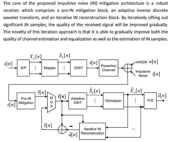
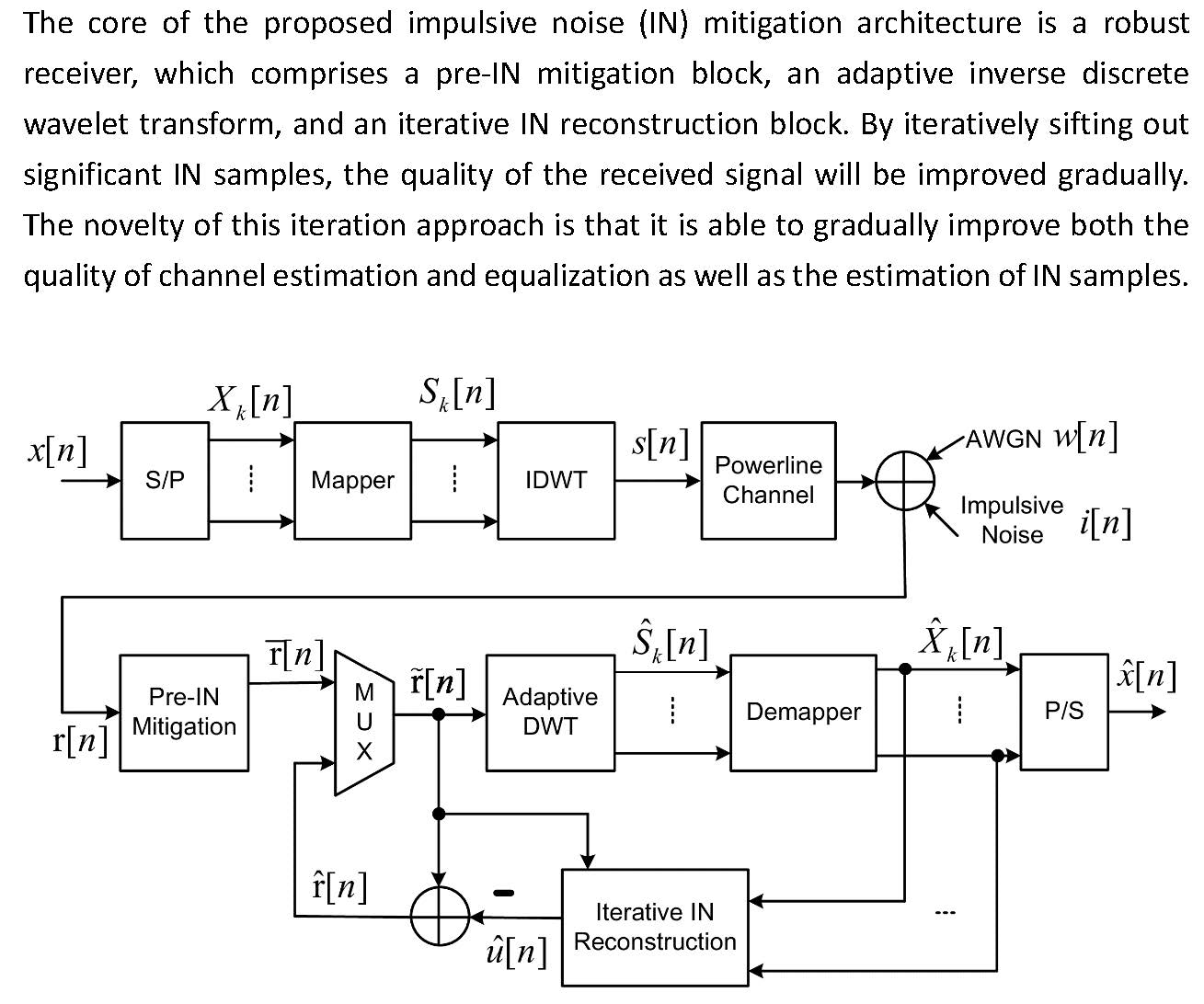
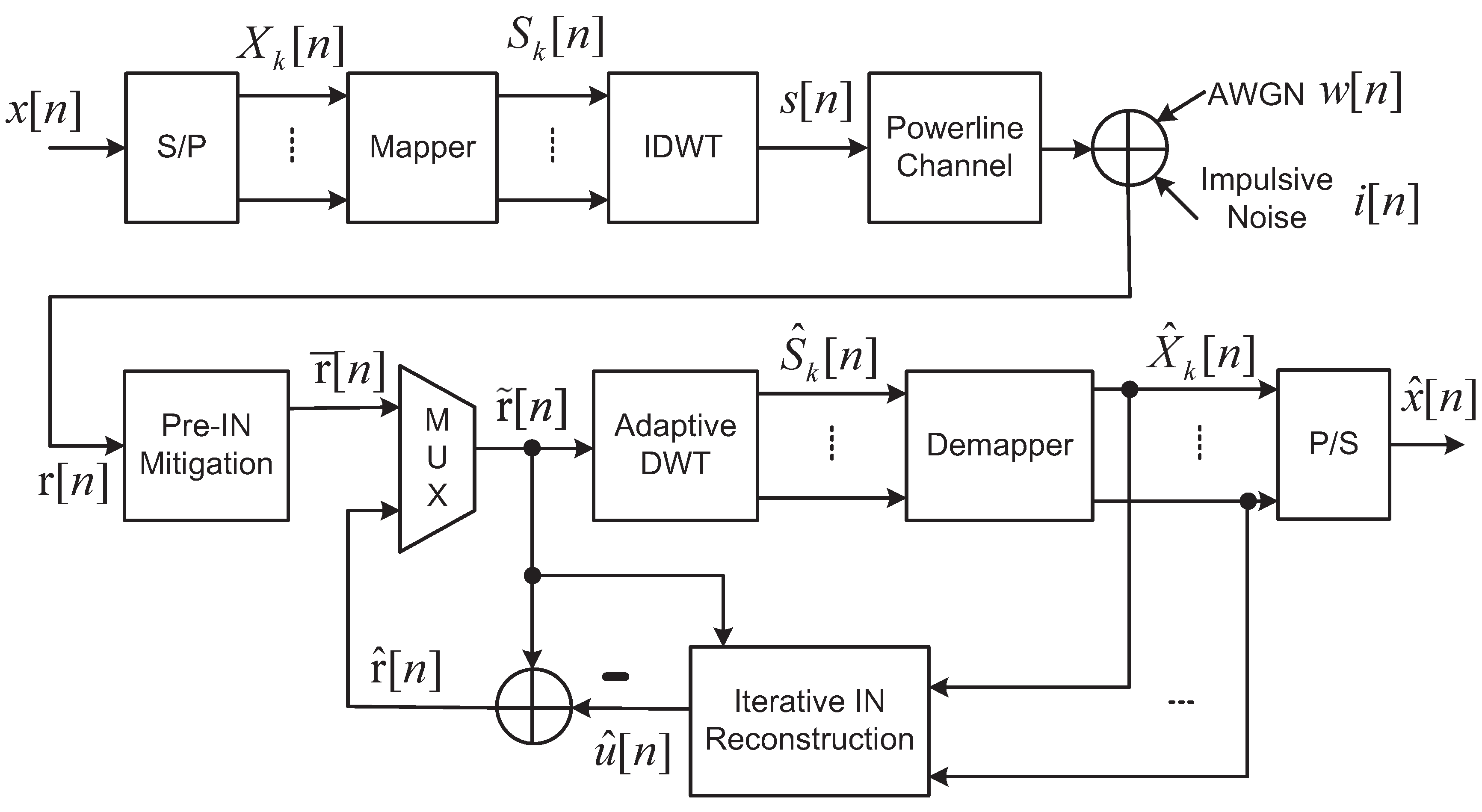
Figure 1 presents the system model of our proposed IN mitigation scheme for wavelet-OFDM PLC. The details of each block are described below.
2.1. Transmission Using IDWT
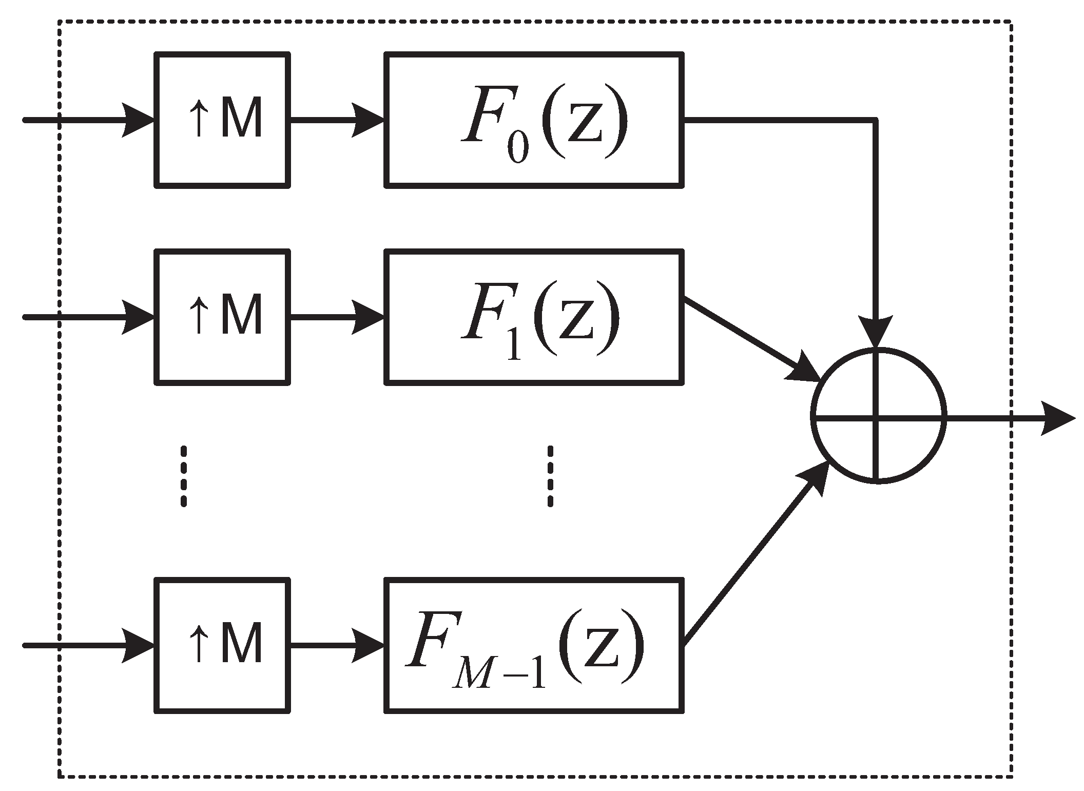
First, a serial-to-parallel (S/P) block converts the binary information source into M parallel subchannels, where we denote as the information source on the k-th subchannel. Next, is assumed to be mapped into the data symbol with a pulse amplitude modulation (PAM) scheme by a mapper. Then, an IDWT block converts the carriers to the time domain data . The IDWT for baseband communication is the synthesis side of a cosine modulated filter bank (CMFB). The IDWT block depicted in Figure 1 is detailed in Figure 2. IDWT operations involve the application of M synthesis filters. Each input signal is up-sampled using factor M and passed through a set of synthesis filters. Without loss of generality, we consider the baseband transmission scenario, in which the number of subchannels and the length of prototype filter . Note that is the overlapping factor, which implies that the symbol duration in the wavelet-OFDM system is extended over g consecutive symbols so that a guard interval is not used. We use to denote the Z-transform of the k-th synthesis filter , which can be described as follows:
where is the index of the subchannel, is the prototype filter with coefficients given in [11] (Annex B), and equals 0 or . By adding the M output of the synthesis filters, we have the channel inputs at the output of the IDWT block.
2.2. Powerline Channel Model
Powerline channels can generally be modeled as multipath channels. Zimmerman [25] proposed using the following frequency response to model the multipath effects caused by the powerlines:
where denotes the number of paths, is the weighting factor, and are the attenuation parameters, is the length of the channel, is the exponent of the attenuation factor, and is the delay associated with the i-th path.
2.3. Additive Noise Model
For indoor BB-PLC systems, asynchronous IN is the dominant source of noise [26]. In this paper, we consider two additive noise sources: background noise and asynchronous IN. We assume that background noise is additive white Gaussian noise (AWGN) with zero mean and variance of . The asynchronous IN is modeled as Bernoulli-Gaussian (BG) IN [27] with zero mean and variance and can be described as follows:
where denotes the Bernoulli process with a probability of success p and is the white Gaussian process with zero mean and variance . Note that we use the occurrence probability of IN p and the Gaussian-to-impulsive-noise ratio (GINR) to characterize the intensity of the IN. A higher value for p and smaller value for indicate a situation with a stronger noise within a channel. The probability density function (PDF) of the aggregated noise seen by the receiver is given as follows:
where denotes the Gaussian PDF, which is defined by:
where and , respectively, denote the associated mean and variance. Thus, the received signal can be expressed as follows:
where is the channel input signal; denotes the channel impulse response (CIR) of the powerline; and ⊗ represents the convolution operation.
2.4. Proposed Receiving Block
In accordance with the iterative IN mitigation approach in Reference [22], the received signal is clipped by a pre-IN mitigation block. A multiplexer (MUX) is then used to select the input signal of the adaptive DWT block, which outputs the symbols for each subchannel. The MUX selects a less contaminated received signal as the input for the adaptive DWT block. We denote as the output signal of the adaptive DWT block for the k-th subchannel. The signal for each subchannel is then demapped and applied to the iterative IN reconstruction block to estimate the IN data . This makes it possible to obtain a received signal of greater clarity by subtracting the estimated IN from the input signals of the adaptive DWT block, i.e., . Following this iterative procedure, a parallel-to-serial (P/S) block converts into the estimated information source .
3. Proposed IN Mitigation Scheme
3.1. Pre-IN Mitigation
The Kurtosis value of is defined as:
where represents expectation operation; and , respectively, denote the mean and standard deviation of . If the received signal is infected by strong IN, then holds. Previous work has revealed that disabling the blanking function of the pre-IN mitigation block is desirable, due to the fact that [28]. Otherwise, the pre-IN mitigation block nullifies portions of the strong IN samples, as follows:
where is an adaptive threshold [22], which can be calculated as follows:
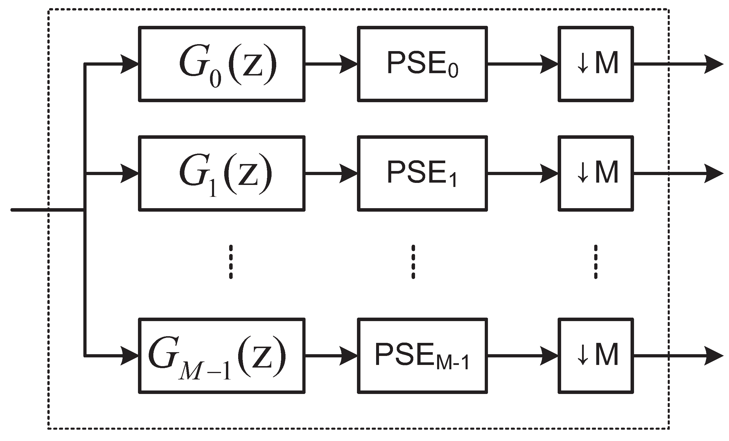
3.2. Adaptive DWT
After pre-IN mitigation, is input to the adaptive DWT block. The adaptive DWT block (see Figure 3) comprises an M-subchannel analysis filter bank, a per-subchannel equalizer (), and a down-sampling operation with a factor M. Note that denotes the Z-transform of the k-th analysis filter , which can be expressed as follows:
where is the index of the subchannel, is the prototype filter, and equals 0 or . The is a finite impulse response (FIR) adaptive filter, used to equalize the powerline channel within the k-th subband. Specifically, equalizes the equivalent channel . In this paper, we employ the variable step-size normalized least mean square (VSS-NLMS) algorithm [24] to train the equalizer to alleviate the impact of IN samples on the training process. The weight updating recursion for can be expressed as follows:
where denotes the weight vector with length at time index n; denotes the regressor vector; the superscript T denotes the transpose operator; and is the error signal associated with the k-th PSE, which can be expressed as follows:
The desired signal is the input of at the IDWT block; is a small positive constant to prevent numerical errors during the weight updating process, and is the variable step-size, which can be calculated as follows:
where is a small positive number; is the estimated variance of the desired signal, which can be calculated using the following recursion:
is the estimated variance of the output signal of the , which can be calculated as follows:
and is the estimated variance of the error signal of the , which can be calculated as follows:
where is the smoothing factor. After down-sampling by a factor of M, we obtain the output of the adaptive IDWT with respect to the k-th subchannel (). This output is then de-mapped to .
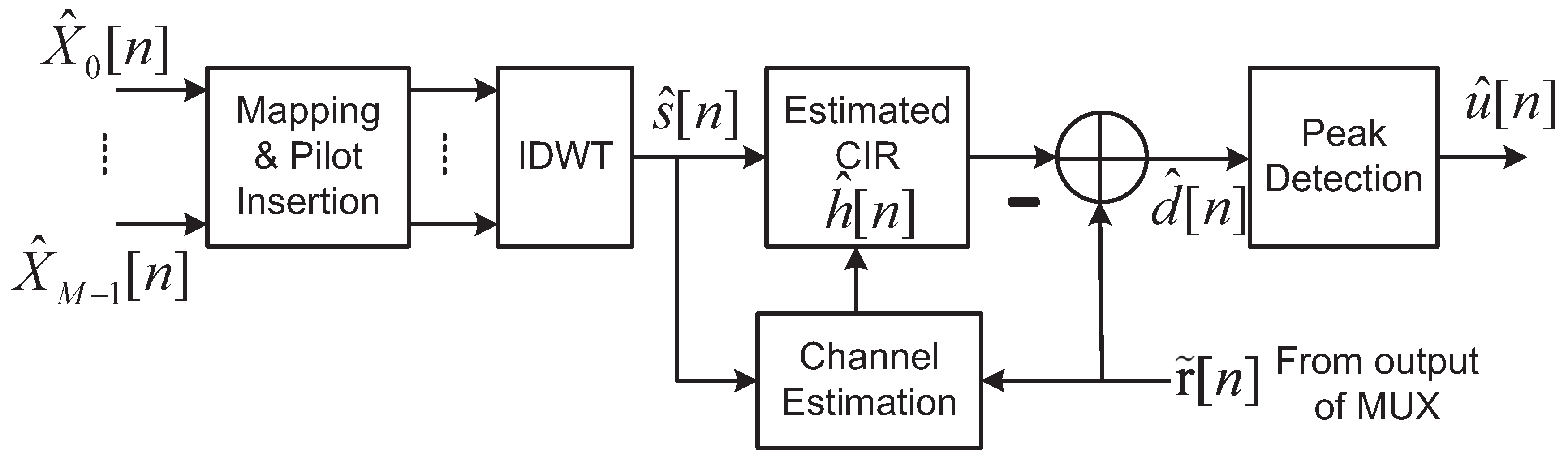
3.3. Iterative IN Reconstruction
Figure 4 details the proposed iterative IN reconstruction block. After re-mapping and pilot-insertion, we can estimate the input of the IDWT block on the transmitter side. Thus, if an estimate of the CIR is available, then it is possible for the IN to be re-generated as follows:
However, and are not exactly the same with and , respectively. Thus, for the samples in , only the samples with large amplitude are reliable estimation for the IN. This leads us to use a peak detector to enhance the reliability of the estimation process, such that only significant estimates of are retained. The operation involving the peak detector can be expressed as follows:
where is an adaptive threshold for the peak detector [22]. Channel estimation can be performed using the following recursions:
where denotes the weight vector with length at time index n; denotes the input regressor vector; is a small positive constant used to prevent numerical errors during the weight updating process; and is an error signal, which can be expressed as follows:
is the variable step-size, which can be calculated as follows [24]:
where is a small positive number; is the estimated variance of the desired signal, which can be calculated using the following recursion:
is the estimated variance of the output signal of the channel estimator which can be calculated as follows:
and is the estimated variance of the error signal of the channel estimator which can be calculated as follows:
where is the smoothing factor.
When the estimated IN becomes available, we are able to obtain a cleaner received by subtracting from , such that in the following iteration, becomes less contaminated. As a result, the mis-adjustments imposed by the equalizers and channel estimator are iteratively reduced. In cases where more iterations are unnecessary, the output of the de-mapper passes through a P/S block to produce the estimation of the information that has been transmitted.
3.4. Computational Complexity
The additional computational complexity incurred by the proposed IN mitigation algorithm mainly comes from the pre-IN mitigation block, the adaptive per-subchannel equalizer, and the iterative IN reconstruction block. We list these additional computational complexity as follows:
- To train the coefficients of the , the calculation of Equations (11)–(13) is necessary. The computation of the variable step-size needs 9 multiplier, one divider, 6 adders, and one square-root operation. The calculation of the error signal requires multipliers and adders. The weight updating recursion needs multipliers, one divider, and adders. Thus, for M per-subchannel equalizers, it totally requires multipliers, adders, dividers, and M square-root operations.
- In addition to one additional IDWT operation, the main computation burden in the iterative IN reconstruction block is resulted from the calculation of Equations (19)–(21). Assuming that the channel estimator is implemented by an FIR filter of length , then the calculation of the recursion (19) needs multipliers, one divider, and adders; the calculation of Equation (20) needs multipliers and adders; the calculation of Equation (21) needs 9 multiplier, one divider, 6 adders, and one square-root operation. Thus, it requires about multiplier, 7 dividers, adders, and one square-root operation in total.
With the fixed number of subchannel M, the main computational cost is linear growth with respect to . Thus, the additional computation complexity associated with our IN mitigation scheme is affordable.
4. Simulation Results
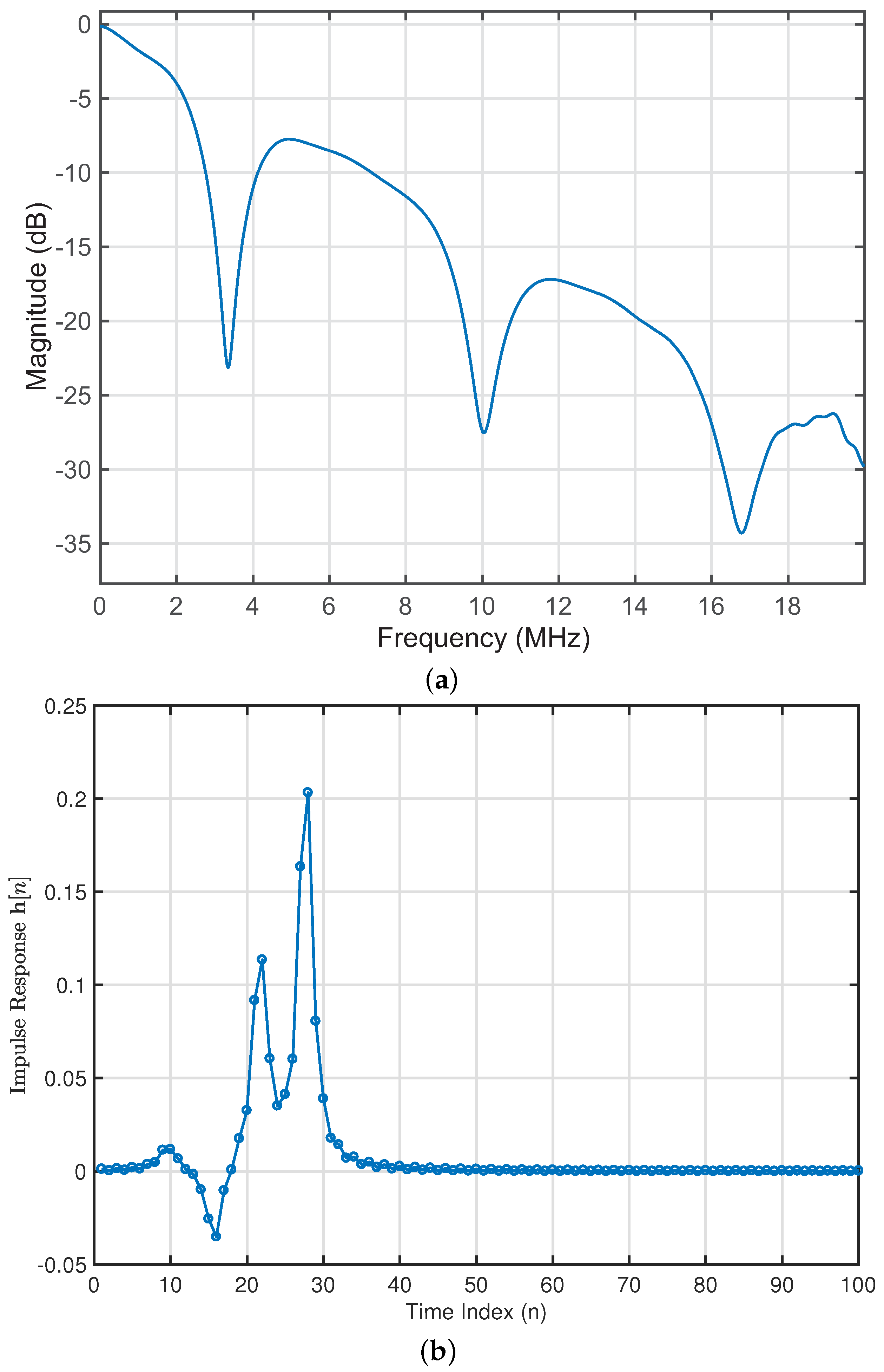
We evaluated the performance of the proposed IN mitigation algorithm by establishing transmitters for use in a wavelet-OFDM PLC system in accordance with IEEE 1901 specifications [11]. The frequency band was 1.8 MHz to 28 MHz, and the modulation was assumed to be 2-PAM. Table 1 lists the parameters of a four-path channel model [25] and the corresponding magnitude and impulse responses are illustrated in Figure 5.
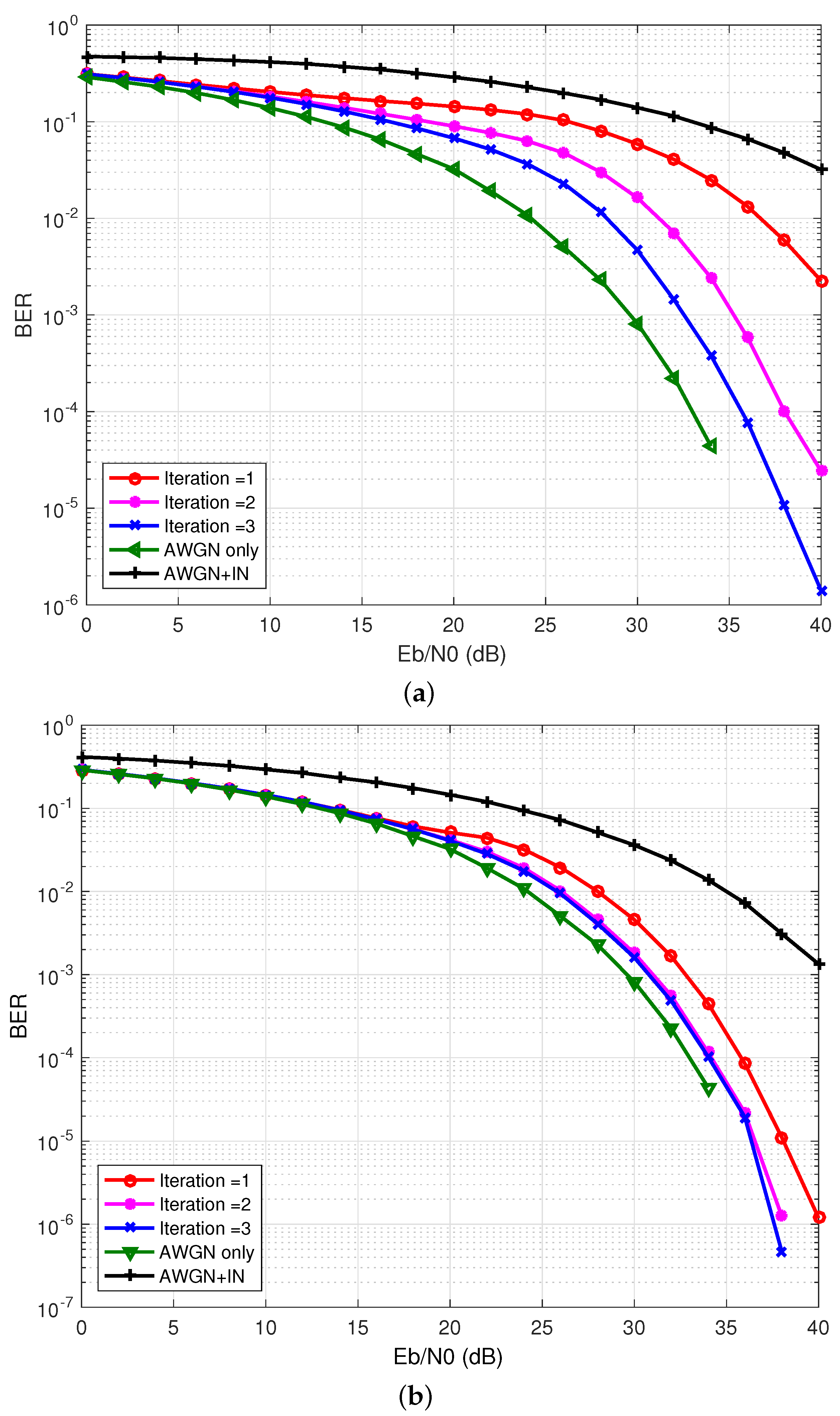
Using the BG IN model described in Equation (3), we considered two IN environments: (1) strongly-disturbed IN (p = 0.1 and = 0.01) and (2) weakly-disturbed IN (p = 0.01 and = 0.1). The performance metric was the BER performance. The effectiveness of the proposed iterative IN mitigation method is confirmed in Figure 6. In the strongly-disturbed case, the required to achieve BER of were as follows: iteration 1 (36 dB), iteration 2 (32 dB), and iteration 3 (28 dB). However, in the weakly-disturbed case, the improvements in were marginal. Note that , which denotes the ration of energy per bit () to noise power spectral density (), is an essential parameter in digital communication systems. It can be treated as a normalized signal-to-noise ratio (SNR) measurement, i.e., SNR per bit. Therefore, for a target BER, we prefer that the required is as small as possible; on the other hand, for a fixed value of , we favor that the resulting BER is as low as possible.
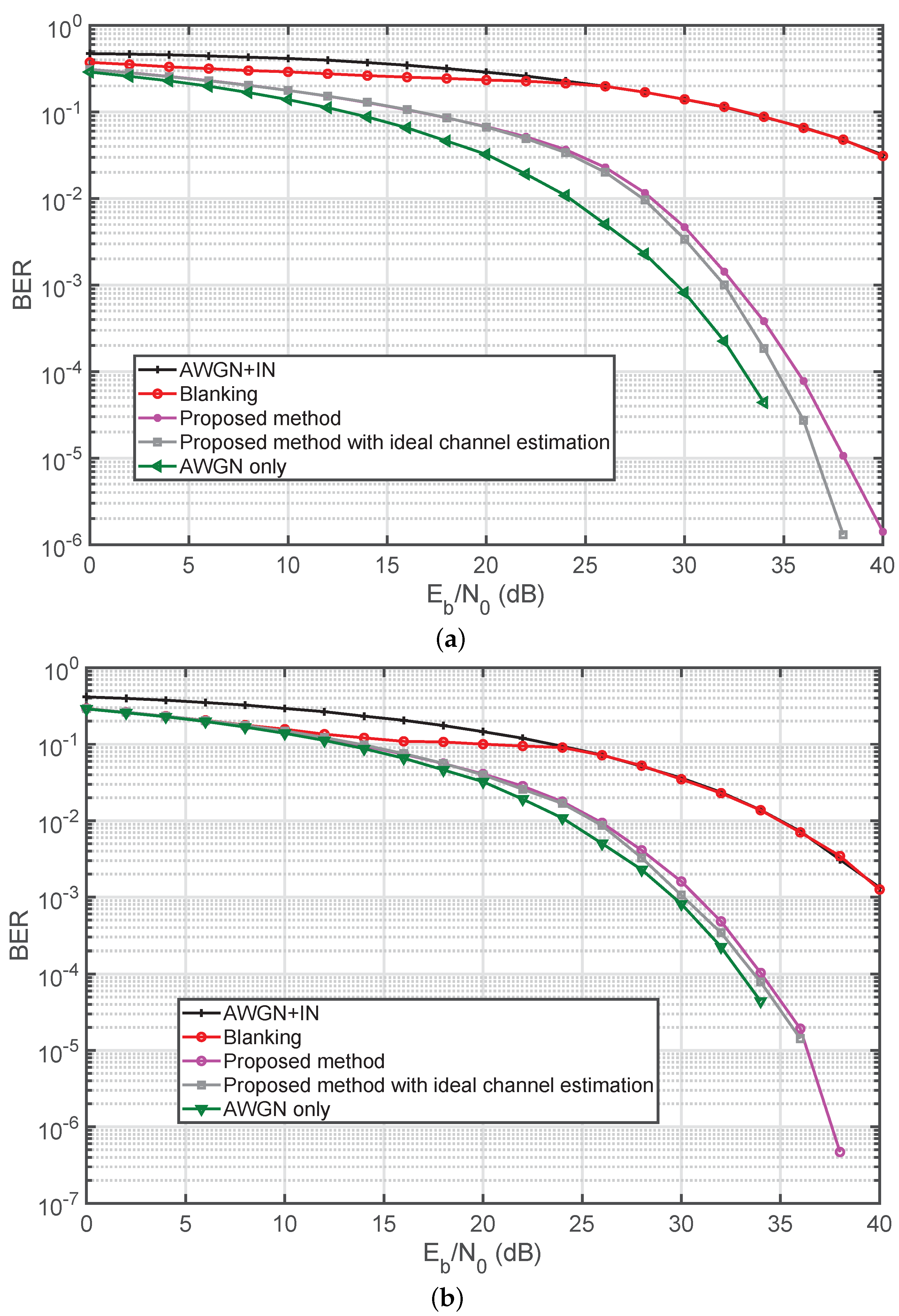
As shown in Figure 7, the conventional blanking method [28] (with blanking device threshold optimized empirically) resulted in poor BER performance. Specifically, only subtle improvements (in terms of the BER ) were obtained when was below 24 dB. When exceeded 24 dB, no blanking was performed. In contrast, the proposed method with estimated channel impulse response achieved BER performance on par with what can be obtained when the channel information is known exactly. Compared to the case with no IN, the loss in at were as follows: strongly-disturbed IN (2.5 dB) and weakly-disturbed IN (0.5 dB).
5. Conclusions
This paper proposes an enabling technology for BB-PLC-based AMI. Specifically, we present a robust iterative receiver to combat IN in wavelet-OFDM-based PLC systems. The proposed receiver iteratively eliminates IN in two stages. In the first stage, a pre-IN block is used to eliminate the most prominent portions of the IN source. The second stage employs an adaptive IDWT block, which serves as an analytical filter bank and adaptively equalizes each subchannel, and an IN reconstruction block. Note that the IN reconstruction block iteratively estimates samples with pronounced residual IN that were not detected by the pre-IN block in the first stage. Simulation results confirmed that the proposed scheme is able to reduce the impact of IN on BER performance, bringing it down to an acceptable level. Compared to the case with no IN, the loss at were as follows: strongly-disturbed IN (2.5 dB) and weakly-disturbed IN (0.5 dB).
Author Contributions
Y.-R.C. was the principle investigator of the funding project and conceived and designed the architecture of the iterative wavelet-OFDM PLC receiver; H.-C.Y. was a part-time research assistant in this project and implemented all simulation codes.
Funding
This research was funded by Ministry of Science and Technology (MOST), Taiwan, under Grant MOST 104-2221-E-197-013.
Conflicts of Interest
The authors declare no conflict of interest.
References
- Ikpehai, A.; Adebisi, B.; Rabie, K.M. Broadband PLC for Clustered Advanced Metering Infrastructure (AMI) Architecture. Energies 2016, 9. [Google Scholar] [CrossRef]
- Kim, D.S.; Chung, B.J.; Chung, Y.M. Statistical Learning for Service Quality Estimation in Broadband PLC AMI. Energies 2019, 12. [Google Scholar] [CrossRef]
- Zhang, J.; Hasandka, A.; Wei, J.; Alam, S.M.S.; Elgindy, T.; Florita, A.R.; Hodge, B.M. Hybrid Communication Architectures for Distributed Smart Grid Applications. Energies 2018, 11. [Google Scholar] [CrossRef]
- Zambroni de Souza, A.C.; Castilla, M. Microgrids Design and Implementation, 1st ed.; Springer International Publishing: Cham, Switzerland, 2019. [Google Scholar]
- Graf, N.; Tsokalo, I.; Lehnert, R. Validating broadband PLC for smart grid applications with field trials. In Proceedings of the 2017 IEEE International Conference on Smart Grid Communications (SmartGridComm), Dresden, Germany, 23–27 October 2017; pp. 497–502. [Google Scholar]
- Zhang, J.; Meng, J. Noise Resistant OFDM for Power-Line Communication Systems. IEEE Trans. Power Deliv. 2010, 25, 693–701. [Google Scholar] [CrossRef]
- Gianaroli, F.; Pancaldi, F.; Sironi, E.; Vigilante, M.; Vitetta, G.M.; Barbieri, A. Statistical Modeling of Periodic Impulsive Noise in Indoor Power-Line Channels. IEEE Trans. Power Deliv. 2012, 27, 1276–1283. [Google Scholar] [CrossRef]
- Andreadou, N.; Pavlidou, F.N. Modeling the Noise on the OFDM Power-Line Communications System. IEEE Trans. Power Deliv. 2010, 25, 150–157. [Google Scholar] [CrossRef]
- Suraweera, H.; Armstrong, J. Noise Bucket Effect for Impulse Noise in OFDM. Electron. Lett. 2004, 40, 1156–1157. [Google Scholar] [CrossRef]
- Ghosh, M. Analysis of the Effect of Impulse Noise on Multicarrier and Single Carrier QAM Systems. IEEE Trans. Commun. 1996, 44, 145–147. [Google Scholar] [CrossRef]
- IEEE Standard for Broadband over Power Line Networks: Medium Access Control and Physical Layer Specifications; IEEE Std 1901-2010; IEEE Standards Association: Piscataway, NJ, USA, 2010; pp. 1–1586. [CrossRef]
- Koga, H.; Kodama, N.; Konishi, T. High-speed power line communication system based on wavelet OFDM. In Proceedings of the 2003 IEEE 7th International Symposium on Power Line Communications and Its Applications, Kyoto, Japan, 26–28 March 2003; pp. 226–231. [Google Scholar]
- Zhidkov, S. Analysis and Comparison of Several Simple Impulsive Noise Mitigation Schemes for OFDM Receivers. IEEE Trans. Commun. 2008, 56, 5–9. [Google Scholar] [CrossRef]
- Papilaya, V.N.; Vinck, A.J.H. Investigation on a new combined impulsive noise mitigation scheme for OFDM transmission. In Proceedings of the 2013 IEEE 17th International Symposium on Power Line Communications and Its Applications, Johannesburg, South Africa, 24–27 March 2013; pp. 86–91. [Google Scholar]
- Kim, Y.; Bae, J.N.; Kim, J.Y. Performance of Power Line Communication Systems with Noise Reduction Scheme for Smart Grid Applications. IEEE Trans. Consum. Electron. 2011, 57, 46–52. [Google Scholar] [CrossRef]
- Juwono, F.; Guo, Q.; Huang, D.; Wong, K.P. Deep Clipping for Impulsive Noise Mitigation in OFDM-Based Power-Line Communications. IEEE Trans. Power Deliv. 2014, 29, 1335–1343. [Google Scholar] [CrossRef]
- Ndo, G.; Siohan, P.; Hamon, M. Adaptive Noise Mitigation in Impulsive Environment: Application to Power-Line Communications. IEEE Trans. Power Deliv. 2010, 25, 647–656. [Google Scholar] [CrossRef]
- Yih, C. Iterative Interference Cancellation for OFDM Signals With Blanking Nonlinearity in Impulsive Noise Channels. IEEE Signal Process. Lett. 2012, 19, 147–150. [Google Scholar] [CrossRef]
- Zhidkov, S. Impulsive noise suppression in OFDM based communication systems. IEEE Trans. Consum. Electron. 2003, 4, 944–948. [Google Scholar] [CrossRef]
- Chien, Y.; Chen, J.; Xu, S.S. A Multilayer Perceptron-Based Impulsive Noise Detector with Application to Power-Line-Based Sensor Networks. IEEE Access 2018, 6, 21778–21787. [Google Scholar] [CrossRef]
- Barazideh, R.; Niknam, S.; Natarajan, B. Impulsive Noise Detection in OFDM-based Systems: A Deep Learning Perspective. In Proceedings of the 2019 IEEE 9th Annual Computing and Communication Workshop and Conference (CCWC), Las Vegas, NV, USA, 7–9 January 2019; pp. 937–942. [Google Scholar] [CrossRef]
- Chien, Y.R. Iterative Channel Estimation and Impulsive Noise Mitigation Algorithm for OFDM-Based Receivers With Application to Power-Line Communications. IEEE Trans. Power Deliv. 2015, 30, 2435–2442. [Google Scholar] [CrossRef]
- Khan, A.; Shin, S.Y. Linear precoded wavelet OFDM-based PLC system with overlap FDE for impulse noise mitigation. Int. J. Commun. Syst. 2017, 30, e3349. [Google Scholar] [CrossRef]
- Paleologu, C.; Benesty, J.; Ciochina, S. A Variable Step-Size Affine Projection Algorithm Designed for Acoustic Echo Cancellation. IEEE Trans. Audio Speech Lang. Process. 2008, 16, 1466–1478. [Google Scholar] [CrossRef]
- Zimmermann, M.; Dostert, K. A Multipath Model for the Power Line Channel. IEEE Trans. Commun. 2002, 50, 553–559. [Google Scholar] [CrossRef]
- Zimmermann, M.; Dostert, K. Analysis and modeling of impulsive noise in broad-band powerline communications. IEEE Trans. Electromagn. Compat. 2002, 44, 249–258. [Google Scholar] [CrossRef]
- Pighi, R.; Franceschini, M.; Ferrari, G.; Raheli, R. Fundamental performance limits of communications systems impaired by impulse noise. IEEE Trans. Commun. 2009, 57, 171–182. [Google Scholar] [CrossRef]
- Chien, Y.; Chen, Y.; Tsao, H. Signal-quality-aware impulsive noise mitigation for OFDM-based power-line communications. In Proceedings of the 2015 IEEE International Conference on Consumer Electronics—Taiwan, Taipei, Taiwan, 6–8 June 2015; pp. 174–175. [Google Scholar] [CrossRef]
Figure 1.
Proposed system model. DWT = discrete wavelet transform; IDWT = inverse discrete wavelet transform; IN = impulsive noise; S/P = serial-to-parallel; P/S = parallel-to-serial; AWGN = additive white Gaussian noise; and MUX = multiplexer.
Figure 1.
Proposed system model. DWT = discrete wavelet transform; IDWT = inverse discrete wavelet transform; IN = impulsive noise; S/P = serial-to-parallel; P/S = parallel-to-serial; AWGN = additive white Gaussian noise; and MUX = multiplexer.

Figure 2.
Details in an inverse IDWT block with M subchannels.

Figure 3.
Details in an adaptive DWT block with M subchannels.

Figure 4.
Details of the iterative IN reconstruction block. CIR = channel impulse response.

Figure 5.
(a) Magnitude and (b) impulse responses for the four-path channel model.

Figure 6.
Performance of proposed algorithm with different iteration in (a) strongly-disturbed and (b) weakly-disturbed cases.
Figure 6.
Performance of proposed algorithm with different iteration in (a) strongly-disturbed and (b) weakly-disturbed cases.

Figure 7.
Performance comparison of the proposed algorithm (iteration = 3) with other related works in (a) strongly-disturbed and (b) weakly-disturbed cases.
Figure 7.
Performance comparison of the proposed algorithm (iteration = 3) with other related works in (a) strongly-disturbed and (b) weakly-disturbed cases.


Table 1.
Parameters of the Four-path Model.
| Attenuation Parameters | |||||
| Path Parameters | |||||
| i | i | ||||
| 1 | 0.64 | 200 | 3 | −0.15 | 244.8 |
| 2 | 0.38 | 222.4 | 4 | 0.05 | 267.5 |
© 2019 by the authors. Licensee MDPI, Basel, Switzerland. This article is an open access article distributed under the terms and conditions of the Creative Commons Attribution (CC BY) license (http://creativecommons.org/licenses/by/4.0/).
Share and Cite
MDPI and ACS Style
Chien, Y.-R.; Yu, H.-C. Mitigating Impulsive Noise for Wavelet-OFDM Powerline Communication. Energies 2019, 12, 1567. https://0-doi-org.brum.beds.ac.uk/10.3390/en12081567
AMA Style
Chien Y-R, Yu H-C. Mitigating Impulsive Noise for Wavelet-OFDM Powerline Communication. Energies. 2019; 12(8):1567. https://0-doi-org.brum.beds.ac.uk/10.3390/en12081567
Chicago/Turabian StyleChien, Ying-Ren, and Hao-Chun Yu. 2019. "Mitigating Impulsive Noise for Wavelet-OFDM Powerline Communication" Energies 12, no. 8: 1567. https://0-doi-org.brum.beds.ac.uk/10.3390/en12081567
Note that from the first issue of 2016, this journal uses article numbers instead of page numbers. See further details here.