Challenges and Design Requirements for Industrial Applications of AC/AC Power Converters without DC-Link


Institute of Electrical Eng., University of Zielona Góra, 65-516 Zielona Góra, Poland
Energies 2019, 12(8), 1581; https://0-doi-org.brum.beds.ac.uk/10.3390/en12081581
Submission received: 29 March 2019
/
Revised: 19 April 2019
/
Accepted: 22 April 2019
/
Published: 25 April 2019
(This article belongs to the Special Issue Design and Control of Power Converters 2019)
Abstract
:AC/AC converters that do not have a DC energy storage element, such as a matrix chopper and a matrix converter, are increasingly becoming alternatives to conventional two-stage AC/DC/AC converters and thyristor choppers. In such systems, the main DC-link capacitor does not exist, so the system provides more reliable operation and makes it possible to reduce the financial costs of its construction. It should be noted that AC/AC converters without an energy storage element in a form of DC-link capacitors have not been implemented on an industrial scale. The reasons involve technical aspects and cost components. The main aim of this paper is to present some of the challenges and selected design requirements for industrial applications of AC/AC high reliability power converters.
1. Introduction
The development of power electronic converters has led to them being applied in various areas of life, such as: industrial and household applications, renewable energies, Flexible AC transmission systems and micro grids, as well as automotive and transport applications. In the development of power converter topologies, much more attention is being paid to the, reliability [1,2] efficiency and robustness of power electronics converters [3,4,5,6]. Automotive industry and transport have very strict reliability requirements in power electronics systems due to safety requirements. Moreover, the industrial and energy sectors are striving for improvement in the efficiency and robustness of power electronics systems. Likewise, home solutions are often designed as economical and sustainable eco-friendly devices. Additionally, some novel devices have a smaller size, and have achieved higher power density and robustness for very high loads. This is a general trend in all areas of technology. High power density, higher switching frequency, and reduced overall dimensions of passive components and power electronic converters are possible due to the use of power transistors made using silicon carbide (SiC) or gallium nitride (GaN) technology [7,8,9,10].
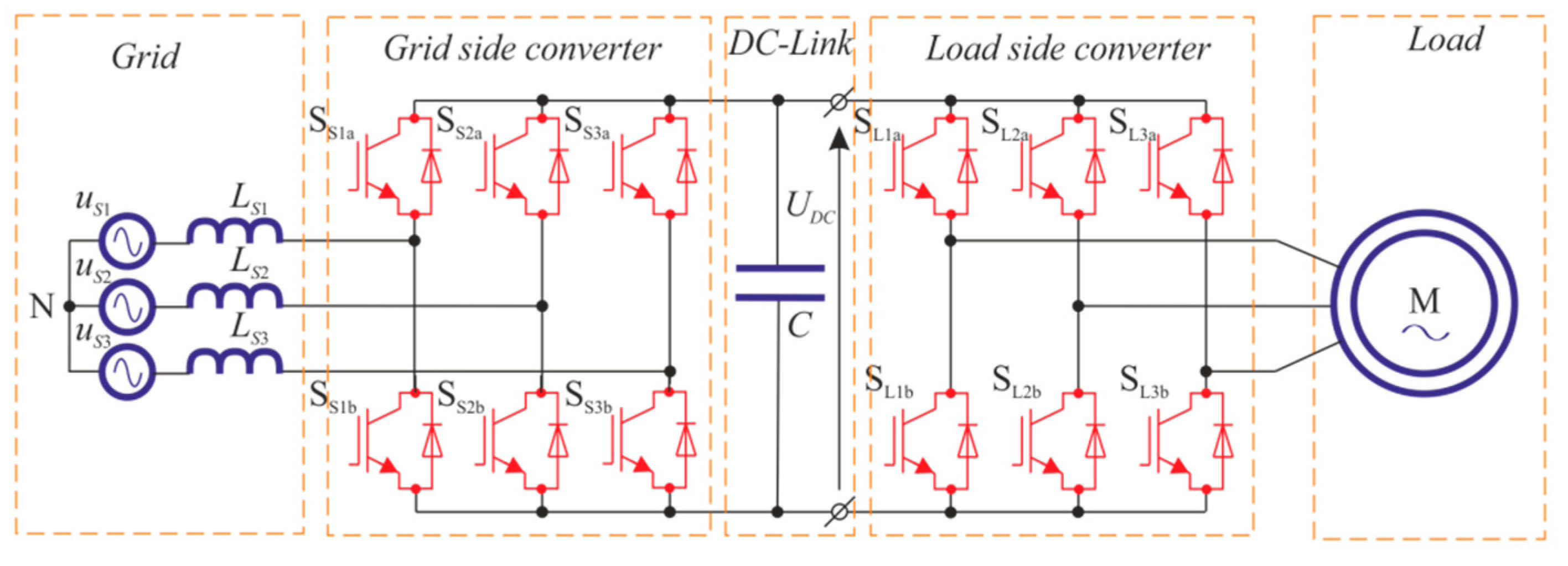
In low-voltage industrial systems, the most commonly used topology is the unidirectional AC/DC/AC converter. The bidirectional (four-quadrant) structure of such a converter is a system called a back-to-back converter (B2B) (Figure 1) [11]. The power stage of converters contains power transistors with a heatsink and heat dissipation system, a DC-link capacitor, an input filter to provide a unit input power factor, and measurement and control units. In medium-voltage industrial systems, multilevel converters with DC-link are commonly used [12,13]. Multilevel converters offer numerous advantages compared with the two-level converter, e.g., better power quality and lower switching losses, low transistor voltage stress, and high voltage capability. It is evident that the multilevel converters will be used for medium voltage or high power electronic systems. However, in general terms, it can be concluded that the two-level converters will be used in low-voltage systems with lower power. In addition, the specialized design of low voltage power electronics converters using SiC or GaN semiconductors, with the optimization of cooling systems, enables the construction of power plants with high efficiency or power densities. In the last decade, apart from the development of power electronics devices, there has also been a significant development of capacitors used in DC circuits. Aluminum electrolytic capacitors are probably the most common capacitors used in the DC-link circuits of modern power electronic converters. In addition, other technologies employed in the production of such capacitors are the multi-layer ceramic structure or the metallized-polypropylene structure [11]. Despite the significant reduction in the dimensions of modern capacitors used in DC circuits, these capacitors still constitute the main component increasing the dimensions, weight, and price of power converters. Furthermore, the capacitor is the component that is most often damaged due to disturbances from the power grid and as a result of improper operation. Figure 2 shows the elements that are most often damaged in circuits of power electronic converters [1,2,14]. For this reason, the most common electrolytic capacitors are the cause of the premature shortening of the lifespan of the converter device [11]. The ageing of DC-link capacitors is manifested by the increase in their equivalent series resistance RESR. The heating up of the electrolyte and its consequent evaporation and deterioration of electrical parameters is the most significant factor in the degradation of the electrolytic capacitor. One of the main reasons for the increase in capacitor temperature is the ripple of the capacitor current. In addition, the second most critical parameter for the failure of the capacitor is its voltage capacity, usually determined by the rated voltage or operating voltage, surge voltage, or allowed short-term maximum voltage. The voltage parameter is so critical that exceeding its nominal values for a few tenths of a second can cause an immediate failure or significantly accelerate the degradation of capacitor nominal parameters. For the presented reasons, in power converters, especially high power ones, particular attention is paid to environmental and operational conditions affecting their lifespan, with special emphasis on DC-link capacitors.
The development of power converters that do not have large capacitors in their structure (DC-link) is an interesting solution to reduce their cost and size. In addition, this can achieve greater reliability and thus extend their operating time [15,16,17,18]. Such converters are often considered an alternative solution for atypical applications and are not found in many industrial applications. One of the main reasons concerns technical aspects related to the small number of available and dedicated semiconductor power devices, as well as DSP processors with a sufficient number of PWM outputs and A/D converters. An additional difficulty is undoubtedly the complex algorithms for modulation of the switch control function and transistor current commutation.
AC/AC converters without DC-link capacitors have several topologies with different functionalities. One of the main functionalities is the possibility to change the frequency of the output current/voltage (fL = const [16], fL = var [15,16,17,18]). In addition, different structures of AC/AC converters are distinguished, such as direct and indirect (with a fictitious DC-link) topology. An example of an AC/AC converter without an intermediate circuit capacitor and fL = const is a matrix controller (matrix chopper), whereas fL = var is a matrix converter.
This paper will present a review of current commercial applications of the AC/AC converters whose topologies do not have a DC energy storage element (capacitor or inductor). Particular attention will be paid to the technological issues and barriers concerning the design of such converters. In addition, possible construction solutions as well as potential applications will be indicated. The originality of this research is in the presentation of requirements and challenges for practical or future-proof applications of AC/AC high-reliability power converters. The paper includes (1) a review of semiconductor power elements dedicated to the discussed converters, (2) an indication of expectations regarding integrated intelligent modules and new SiC technologies, and (3) an indication of the development of modern control techniques (e.g., model predictive control (MPC)). In addition, new application possibilities of the discussed converters in AC power systems, (e.g., compensators for voltage changes) are indicated and their beneficial properties are discussed.
2. Description of Selected Topologies
The analysis presented in the article will be based on topologies of two converters: a matrix controller (chopper) and a matrix converter. Based on these, the main design problems and limitations related to the available components and the industrial application will be indicated.
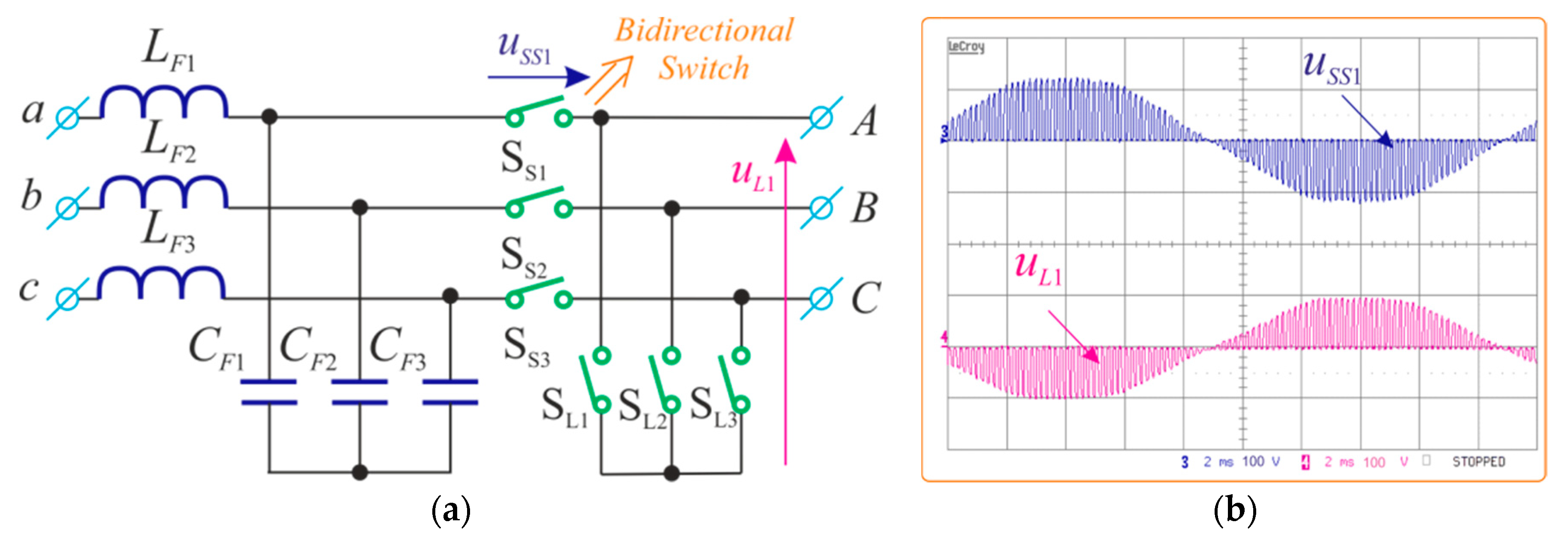
One of the basic applications of AC/AC choppers, as an alternative to thyristor choppers, is in electric drive systems used as a soft-start for an AC motor. Issues with industrial temperature control and lighting intensity control are the further areas of AC/AC chopper application. A schematic diagram of the three phase AC/AC matrix controller power circuit is presented in Figure 3a [16]. The system consists of six bidirectional switches. Three switches are connected to the input terminals, while the other three are connected in parallel to the load. Control of the switches is carried out by means of the PWM signal (Figure 3b), and a duty cycle determines the RMS value of the output voltage. In addition, the choppers have an input low-pass filter to eliminate the higher harmonics components of the current drawn by the converter, which result from the frequency of the PWM signal. The second kind of structure based on the chopper shown in Figure 3a is the matrix-reactance chopper, which also enables the increase in amplitude of the output voltage [19] as well as various other types of compensators for AC voltage fluctuations in the power grid [20,21].
The main advantages of the AC/AC chopper compared to the classic thyristor chopper are derived from the sinusoidal current drawn from the mains, and the use of LC output filters to obtain sinusoidal output voltages. Such properties allow one to work with the unit input power factor and use these choppers in systems of electricity conditioners [20,21]. The high switching frequency of the power transistors makes it possible to minimize the sizes for the input and output LC passive filters. The disadvantage of chopper devices is the increased internal losses resulting from the large number of power transistors and the necessity of using additional snubber devices on each of the power electronics switches or of using overvoltage protection of bidirectional switches with a clamp circuit [16,22].
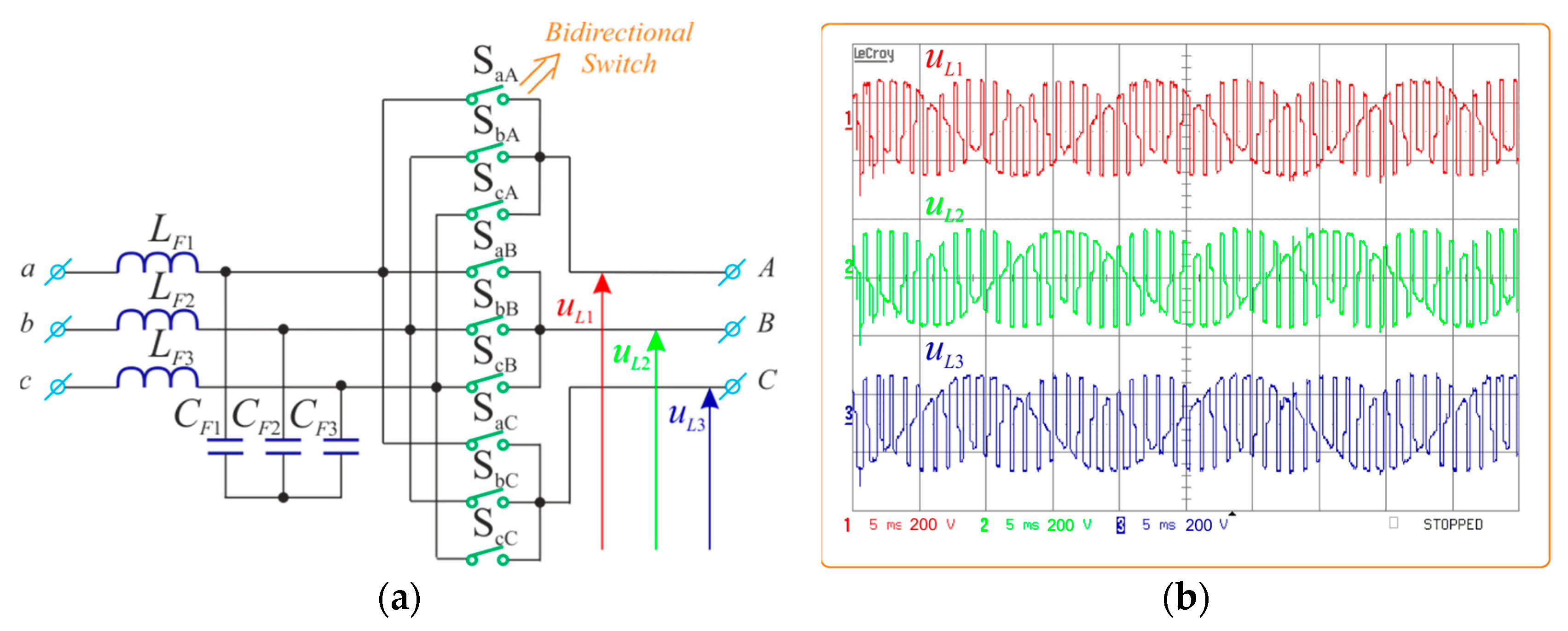
The most widely known of frequency converters (fL = var) without DC-link is the matrix converter (MC) in its direct topology shown in Figure 4a [15,16,17,18,22,23,24]. Generally, in three-phase systems, the MC consists of nine bidirectional switches connected in a matrix—each input is connected to each output. Similar to the matrix controller, there is an input low pass filter in the MC topology that fulfills identical functions. MC output voltages are formed from pieces of input voltages, shown in Figure 4b, as exemplary experimental time waveforms.
The MC is a four-quadrant topology with adjustable input power factor and a sinusoidal shape of input and output currents. In addition, the MC is a fully semiconductor device without large capacitor circuit capacitors. Similarly to chopper devices, there is a necessity to use additional overvoltage protection of bidirectional switches with a clamp circuit, where small capacitors accumulating commutation voltage spikes should be used. The disadvantages of the MC are the large number of power transistors and the associated complex control and switching strategies. In addition, the voltage gain of MCs does not exceed 0.866, which, for applications in variable speed drives, requires the use of motors with lower rated voltages.
In both MC and AC/AC chopper topologies, the main elements are bi-directional power electronic switches. These switches allow switching of both the positive and negative sine wave of the supply voltage and, in the case of the MC, the bi-directional power flow. Bidirectional switches, as will be discussed in the next section, have a configuration of transistors and diodes other than those used in classical, commonly used voltage inverters. Therefore, the commercial development of available bidirectional switches in various configurations is important for the development of AC/AC converters without DC-link circuits.
3. Design, Construction, and Implementation Barriers
The development of AC/AC converters encounters problems related to misunderstanding the specificity of their operation, especially in the context of MCs. In this chapter, basic construction problems and development barriers related to technological differences in relation to commonly used frequency converters will be indicated. Barriers hindering development include, among others, a lack of semiconductor components in more complex modules than single transistors, a specific distribution of control signals, a complex transistor switching strategy, and a large number of measuring sensors. However, in spite of these problems, this chapter will indicate the first commercial applications of AC/AC converters without DC-link and provide guidelines for the modular construction of intelligent power modules that would significantly contribute to the development of this technology. An important development impulse may also be the implementation of control methods that are developed for other topologies such as model predictive control. The number of topics discussed in this chapter results from the need to indicate both the application potential and difficulties in designing the discussed converters.
3.1. Power Semiconductors
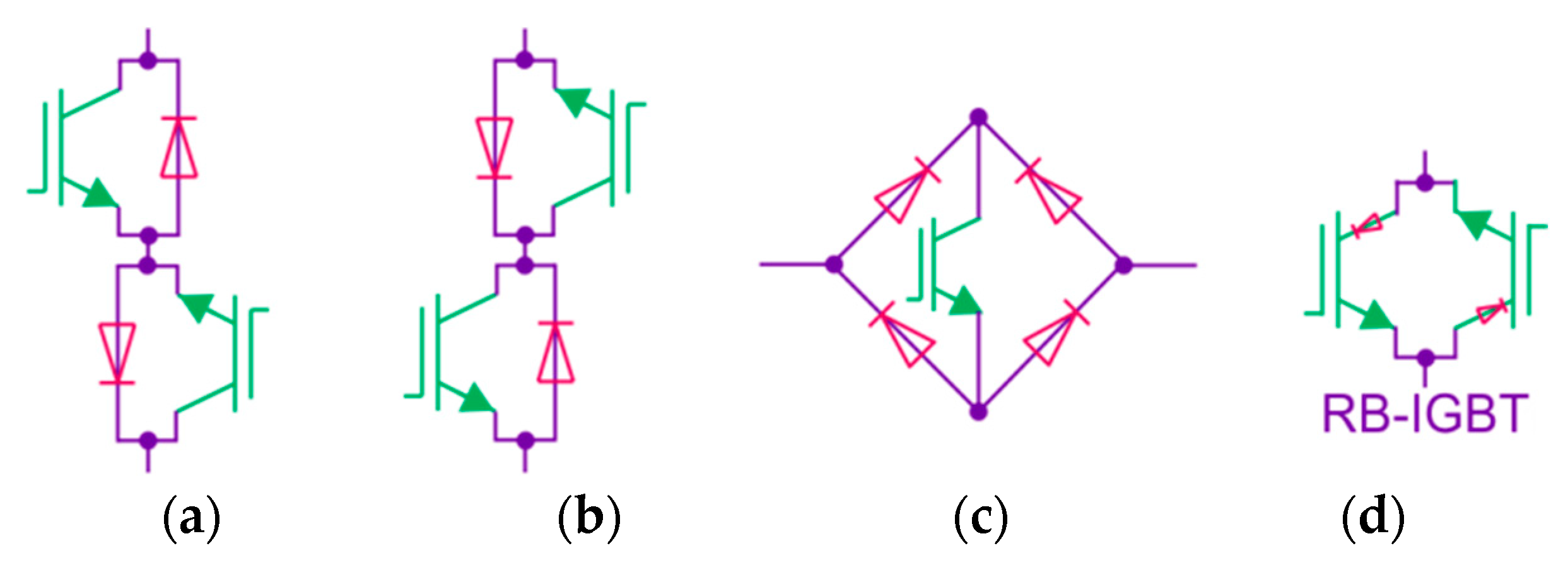
As already mentioned in the previous chapter, bi-directional switches are used in the discussed converters. Basic configurations of such bidirectional switches made in Si technology are presented in Figure 5. Such configurations of Insulated Gate Bipolar Transistor (IGBT) transistors and diodes allow conducting currents in both directions and blocking voltages for positive and negative polarity.
3.1.1. Si Semiconductors
AC/AC converters are full semiconductor systems and must be constructed of bi-directional switches. For power converters commonly used in industry, there are many developed modules containing complex structures on the market for the transistors or diode connections. However, for AC/AC converters, there are very few commercially available semiconductor modules that have bi-directional switches in their structure. As shown in Figure 5, the most commonly used configurations of bi-directional switches are IGBTs with anti-parallel diodes (two topologies, a common collector, and a common emitter). In addition, there are switches with a diode bridge and a single IGBT transistor, and reverse blocking IGBT (RB-IGBT), where anti-parallel diodes can be eliminated [21]. It is possible to build bi-directional switches with a combination of various discrete elements, but the creation of advanced power electronic devices in the form of integrated power modules facilitates a reduction in dimensions of the converter, allows higher power densities, and produces high reliability. Few examples of power modules for the bidirectional switches or complex structures are currently available on the market, though some of these modules are now commercially available. Table 1 lists the selected of manufacturers that have commercially available power modules with bi-directional switches.
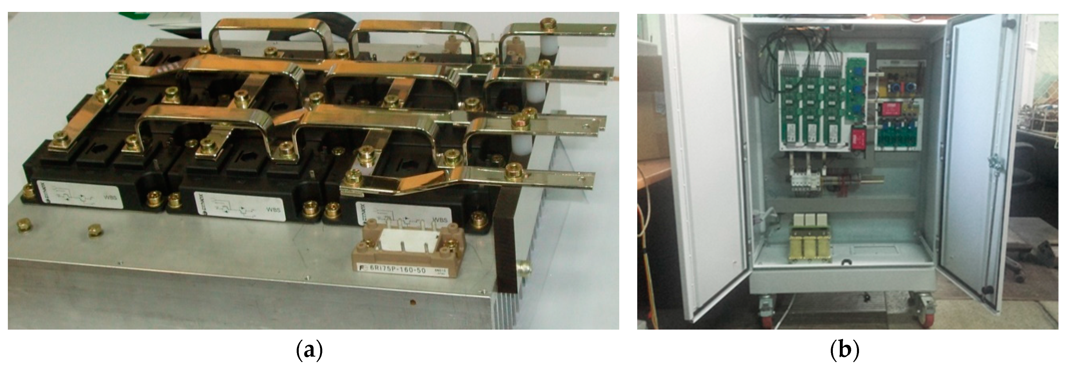
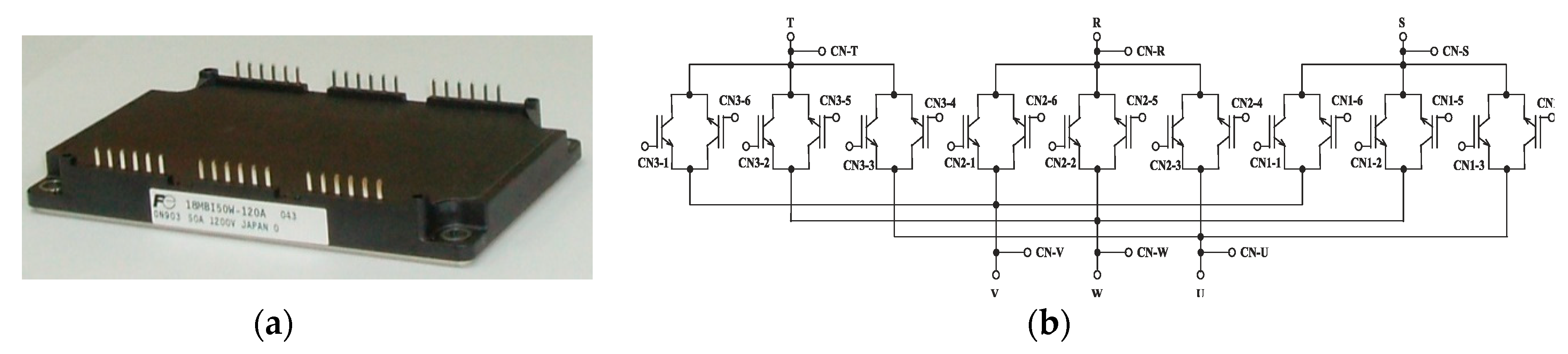
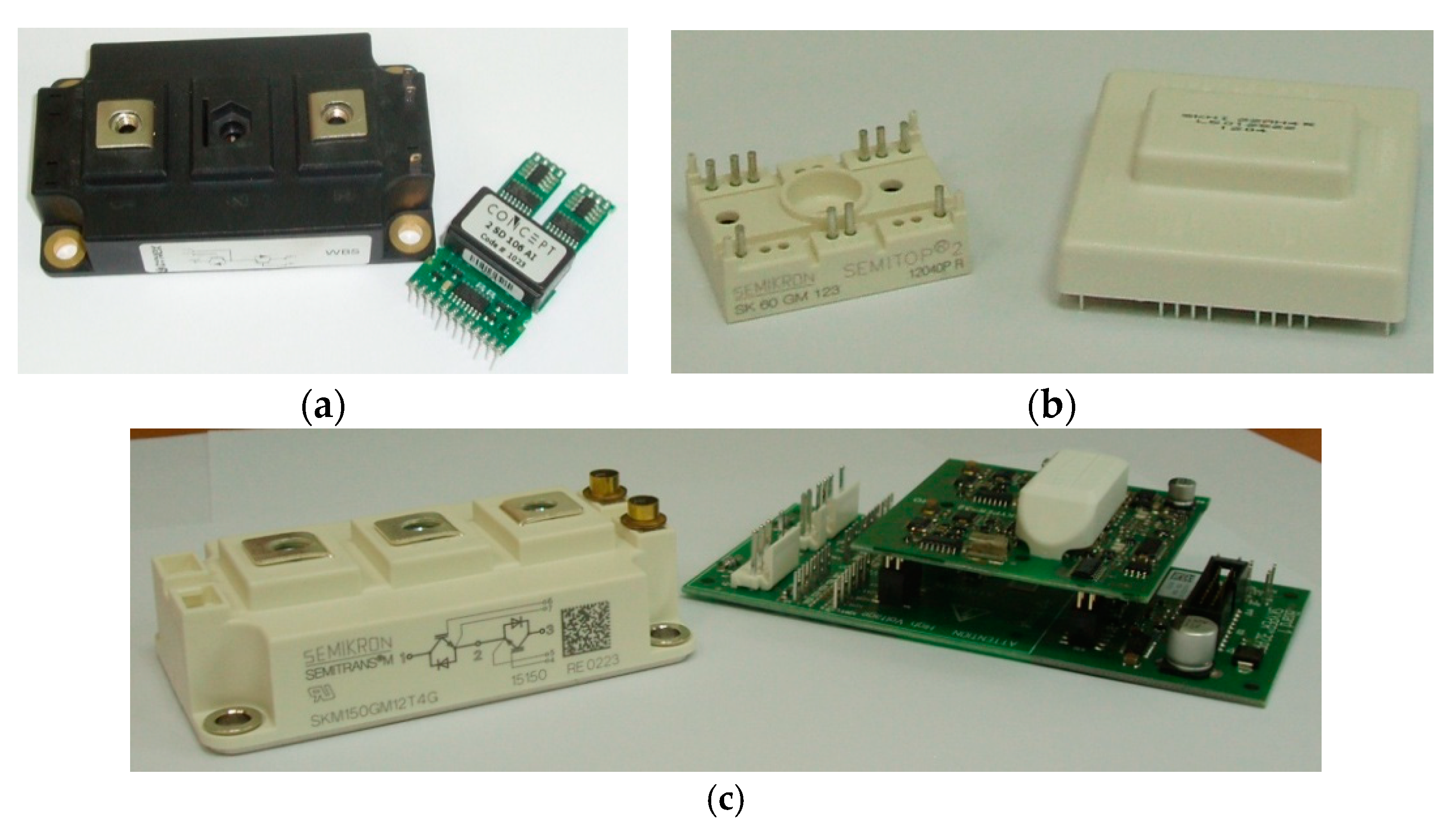
The first example of the use of bi-directional Dynex Semiconductor switches with rated parameters of 1.2 kV and 200 A is illustrated in the structure of the matrix converter shown in Figure 6. An example of a structure containing a single housing topology of a matrix converter with RB-IGBT transistors is the module presented in Figure 7. The module is manufactured by the FUJI Electric company and its nominal parameters are 1.2 kV/50 A. As generally known, in addition to the power element, a dedicated transistor gate driver is also needed. In this case, designers can use existing drivers used in other converter topologies. However, there are dedicated drivers for available bi-directional modules. Examples of such dedicated drivers include Concept [14] drivers for Dynex switches (Figure 8a) and Semicron drivers and transistors presented in Figure 8b,c. These are examples of bi-directional switches. In the catalogues of other semiconductor companies, such solutions are found often and with increasing frequency. Based on the above review, it can be said that the number of dedicated components is gradually increasing over time. It should be noted that, without systematic growth of proposals for new, dedicated components for the design and construction of AC/AC converters, there will be no significant development of these topologies. The main direction of development should be to reduce component costs and increase their reliability.
3.1.2. SiC Semiconductors
Thanks to the development of semiconductor power electronics with silicon carbide (SiC), which has certain advantageous features such as high temperature operation, low losses, and higher switching speeds, a full power electronic converter structure has also been developed. Moreover, thanks to the semi-conductor being made using SiC technology, a further improvement in the converters power density can be achieved. Because this is a technology that has not fully achieved technological maturity, there are some problems in the implementation of power converters with SiC devices due to the high speed of switching devices and the design of devices for the gate drive.
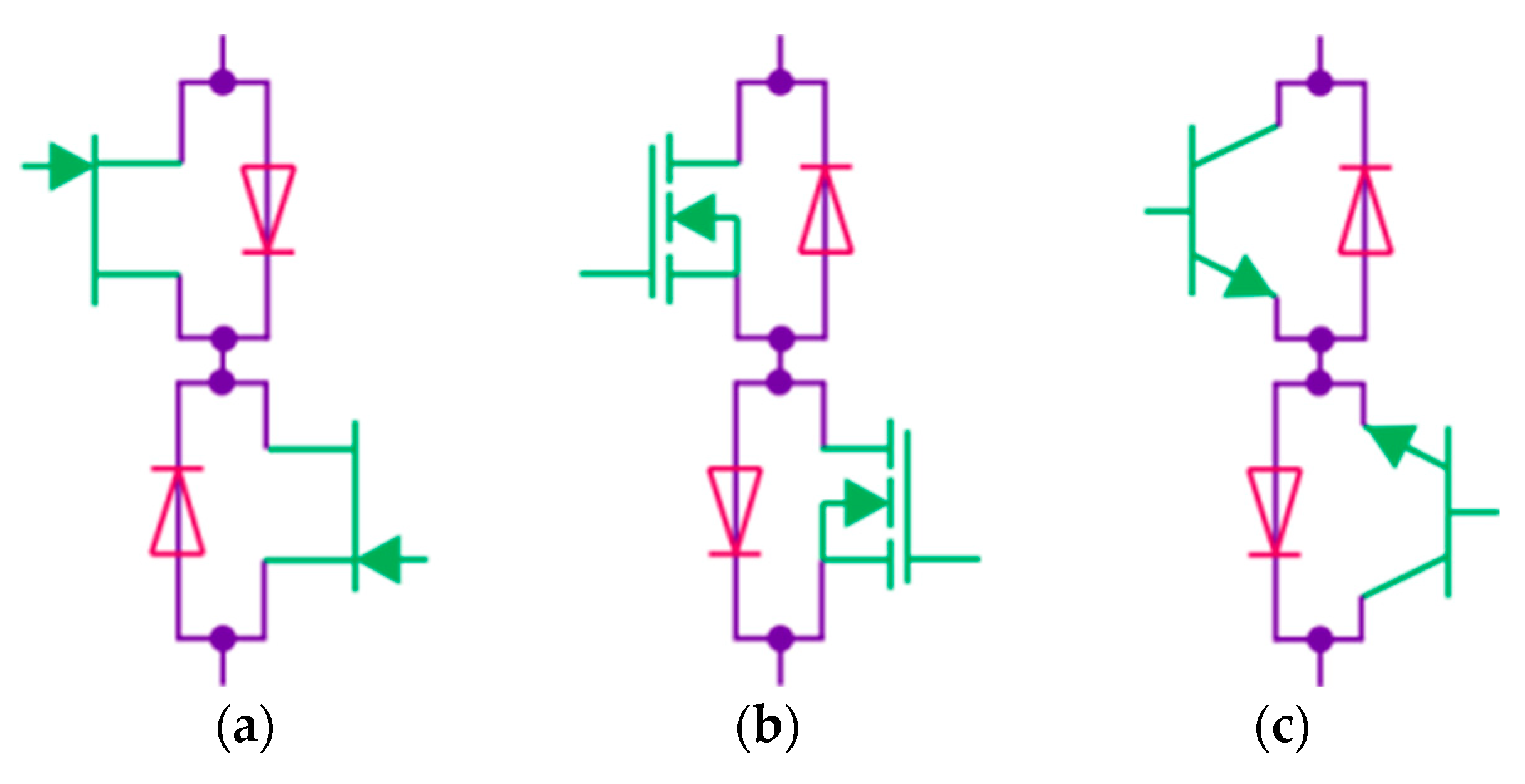
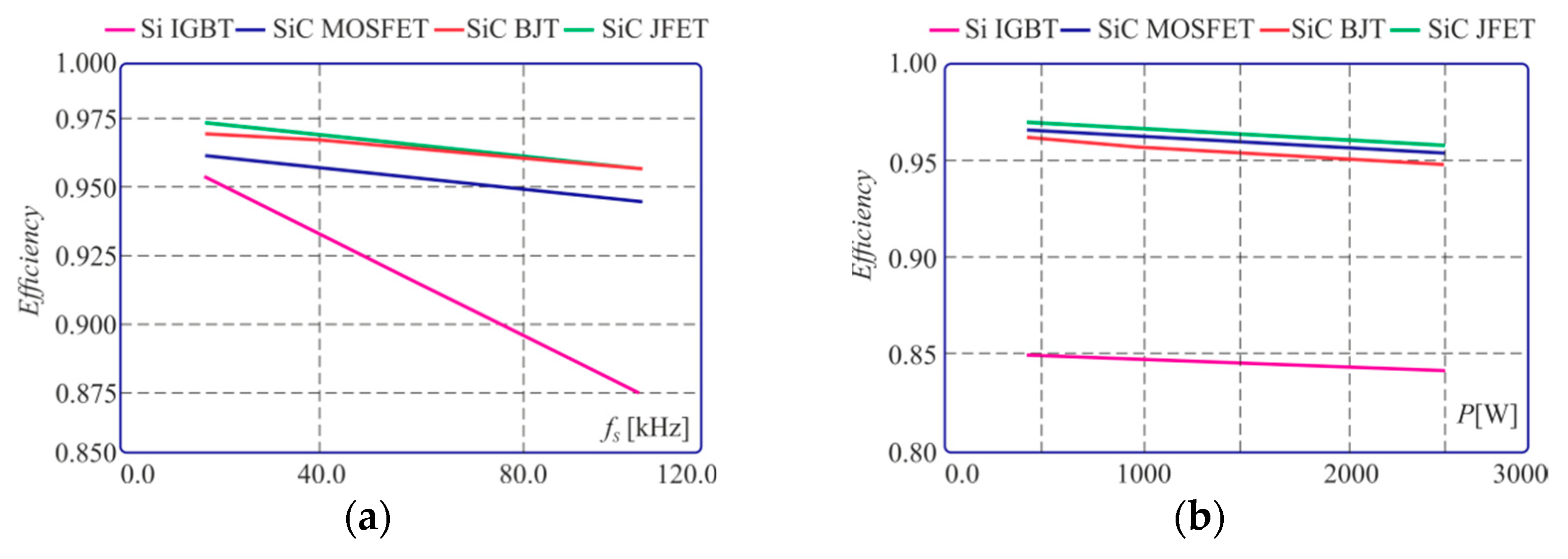
The most promising SiC devices are the normally-off SiC JFET, SiC MOSFET, and SiC BJTs. The bi-directional switch topologies in SiC technology are shown in Figure 9. Potential improvements regarding the efficiency and performance of SiC components in the context of bi-directional power electronics switches are reported in [24,25,26,27]. As demonstrated by existing research, the use of transistors made in SiC technology enables a significant increase in the efficiency of converters for switching frequencies of several dozen kHz. Sample results illustrating the beneficial properties of SiC transistors, taken from [24], are presented in Figure 10.
3.2. Control Units
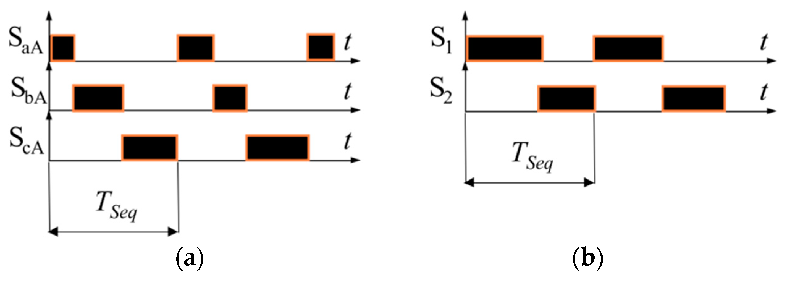
The MC power stage circuit is made up from a table of nine bi-directional switches which provides a total of 18 transistors. The specificity of the MC construction also requires the generation of a PWM switching sequence. In addition, special attention should be paid to maintaining a safe current commutation strategy when the transistors are switched. An additional difficulty in the modulation process of the transistors control functions is the distribution of control pulses in a single period of the control sequence TSeq. Since there are three bidirectional switches connected in one output branch (six transistors) and two or three of them cannot be switched on simultaneously, the switching sequence will be responsible for three switching operations during one period TSeq (Figure 11a). In the classic bridge voltage inverter, for a single branch, there are two transistors working alternately. A pair of complementary control signals are then generated and are negated in relation to each other (Figure 11b). In addition, additional dead times (dead-band) are used to ensure correct current commutation. Modern DSP processors and microcontrollers have built-in PWM modulators that generate complementary control signals that occur in classic bridge voltage inverters with built-in dead time generation functions [28]. The control implementation for the matrix converter using built-in PWM modulators is not simple and requires either multiple-core systems (at least two) or additional logic circuits. It is also possible to solve this problem using software I/O outputs instead of built-in PWM modulator procedures. These are, of course, more complicated solutions than in the classic branches of the inverter bridge.
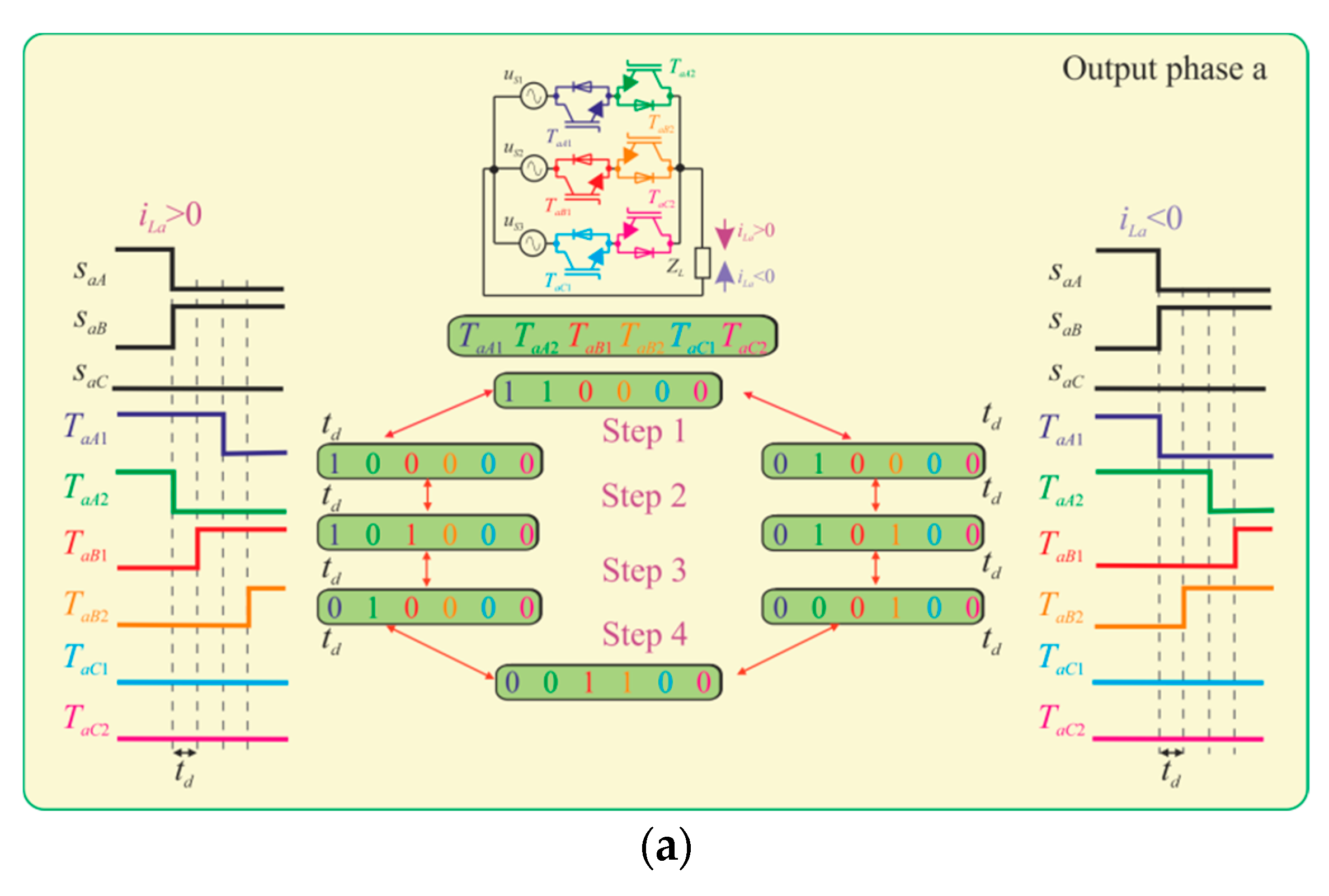
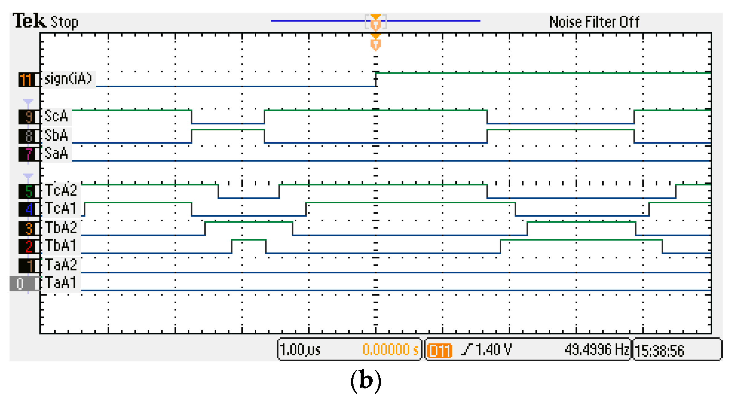
In addition to the algorithm for the modulation of switch control signals in the MC, it is necessary to use complex current switching algorithms for transistors. Several commutation strategies can be found in the scientific literature [17,21], where the most widely known is the four-step current commutation strategy. In this method, the current direction in the output line is used to determine switching sequences of transistors. The commutation process for one output phase is shown in Figure 12a. An analogous switching pattern occurs between any transistors in each MC output stage. Examples of control sequences obtained at the FPGA output are shown in Figure 12b.
The digital implementation of the two presented algorithms of modulation and commutation requires the use of complex computing systems often combining DSP and FPGA devices. [29]. The control algorithms for a given application (electric drive, voltage compensator, etc.) and modulation algorithm are in most cases implemented in the DSP, while the FPGA, observing safe commutation rules, is used in the part related to the separation of control signals and transfer to individual transistors, so as to perform additional tasks to supplement the DSP function.
A significant limitation preventing faster development of AC/AC converters, such as MCs, is the large number of transistors and hence the need for DSPs with a large number of PWM outputs. The solution to this problem may be the rapid development of FPGAs, which has occurred in recent years. In the scientific literature, first articles related to the implementation of complete MC control algorithms implemented solely on FPGA have appeared [30,31]. Such an implementation is much more difficult when advanced mathematical functions such as trigonometric functions are used. Additionally, I/O systems in particular should be defined using a software solution, especially those related to cooperation with A/D and D/A converters. Nevertheless, parallelism and the speed of calculation means that FPGAs can replace DSP processors.
3.3. Measurement of Voltages and Currents
In order to correctly implement the control, modulation, and commutation algorithms in MCs, it is necessary to measure the values of voltages and currents [21,32]. Measured voltage and current signals are used, among others, in (1) semisoft commutation strategies, (2) fault detections, (3) modulation process (e.g., SVM), (4) phase-locked loop (PLL) units, (5) current loops in control algorithms, and (6) the clamp protection circuit. The measuring transducers should ensure galvanic isolation between the measured signals and the components of the control system and match the level of signals to the A/D converters. The most popular voltage and current measurement devices are LEM type transducers [33]. Of course, there are also many other manufacturers of this type of device, e.g., ABB, Honeywell, Allegro Microsystems, and Chen Young [34]. Transducer devices are quite expensive, so the measurement of voltages or currents can also be made on the basis of differential and isolated amplifiers, which are cheaper. Devices with galvanic isolation use optical, capacitive, or inductive insulation barriers. Table 2 presents examples of voltage and current measuring amplifiers as well as selected types of transducers [34].
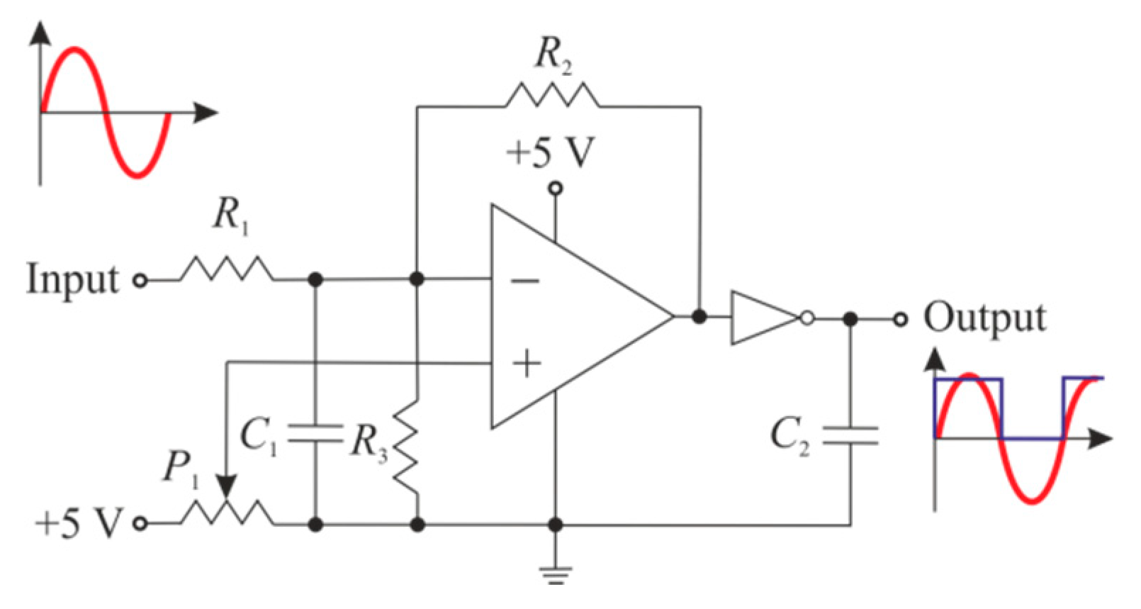
One of the more precise issues related to the measurement of currents in AC/AC converters is the detection of its direction needed to ensure correct commutation of the tan resistors [21]. Due to the inductive nature of the load and the switched output voltage, the currents in the circuits of AC/AC converters contain higher harmonics. Therefore, accurate determination of the current direction is an issue requiring either advanced software algorithms or additional electronic circuits. The software solution for determining the current direction can be implemented using the network voltage synchronization algorithms (PLL) [35]. It is also possible to use an additional electric circuit that will perform the function of determining the current direction in a hardware manner. An example of such a solution based on a zero-crossing detector is shown in Figure 13 [36].
3.4. Commercialization of Prototype Solutions
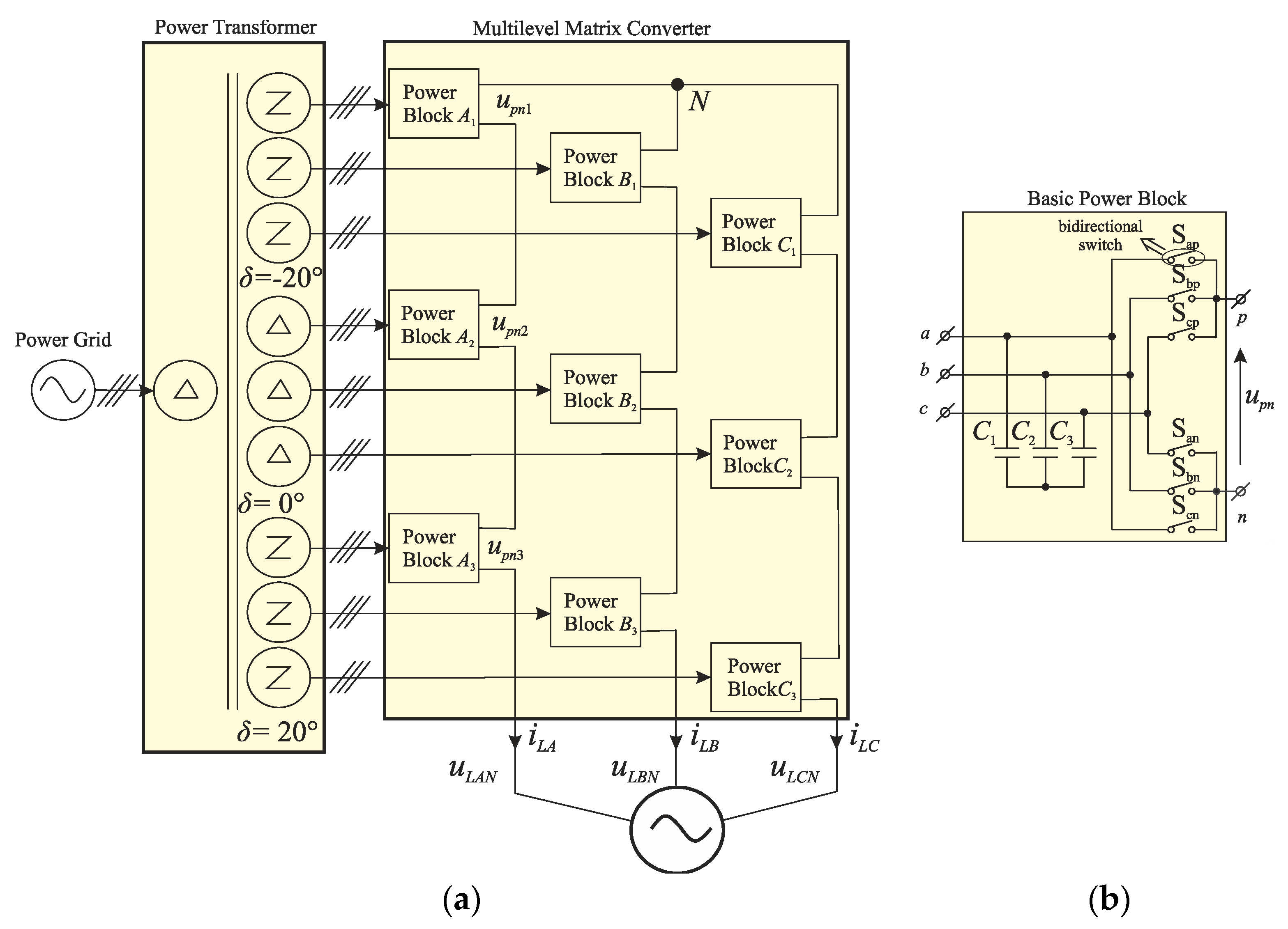
The first major challenge for AC/AC converters without a DC-link element is the commercialization of the semiconductor components and other elements necessary for their design and implementation. The market situation of the semiconductor switches is discussed in Section 3.1.1. A growing number of dedicated semiconductor modules is visible. However, is this enough for faster development of power converters? This question is important because despite the growing interest in scientific research in this field, there are few AC/AC converters without DC-link available on the market. One of the first manufacturers of matrix converters is the Yaskawa Electric Corporation [32]. The Yaskawa products of an MC include low-voltage and medium-voltage solutions. The low-voltage MC solution is the classic matrix converter shown in Figure 7a. The classic MC product portfolio has two voltage levels: 200 V (from 9 to 63 kVA) and 400 V (from 10 to 114 kVA) [32]. In contrast, the solution for medium voltage is designed as a multi-level structure (Figure 14a). It uses a three-phase to single-phase MC structure as a basic power block (Figure 14b). By combining three blocks in series, a phase voltage three times higher than the voltage of a single module can be obtained (Figure 14a). The multilevel MC has similar features to the classical matrix converter. The medium voltage MC product portfolio has two voltage levels: a 3.3 kV level ranging from 200 to 3000 kVA and a 6.6 kV level from 400 to 6000 kVA [32].
3.5. Modular Construction
In commercially available modules dedicated to the discussed converters, there are no solutions for intelligent modules with power semiconductors, protection devices, drivers, or measurement sensors in their structure. This subsection indicates the expectations regarding this type of intelligent solution based on previous experience.
The power-electronic building block (PEBB) is the concept of building converters from basic modules. The effect of this approach is to increase the reliability and dimensions of power electronic converters [37,38]. The PEBB concept is used to integrate the following components into one module: power supply devices, gate drives, communication interfaces, measuring sensors, snubber protection circuits, and other components necessary for the proper operation of the converter. The concept of the PEBB offers a means for hardware standardization of power electronics systems.
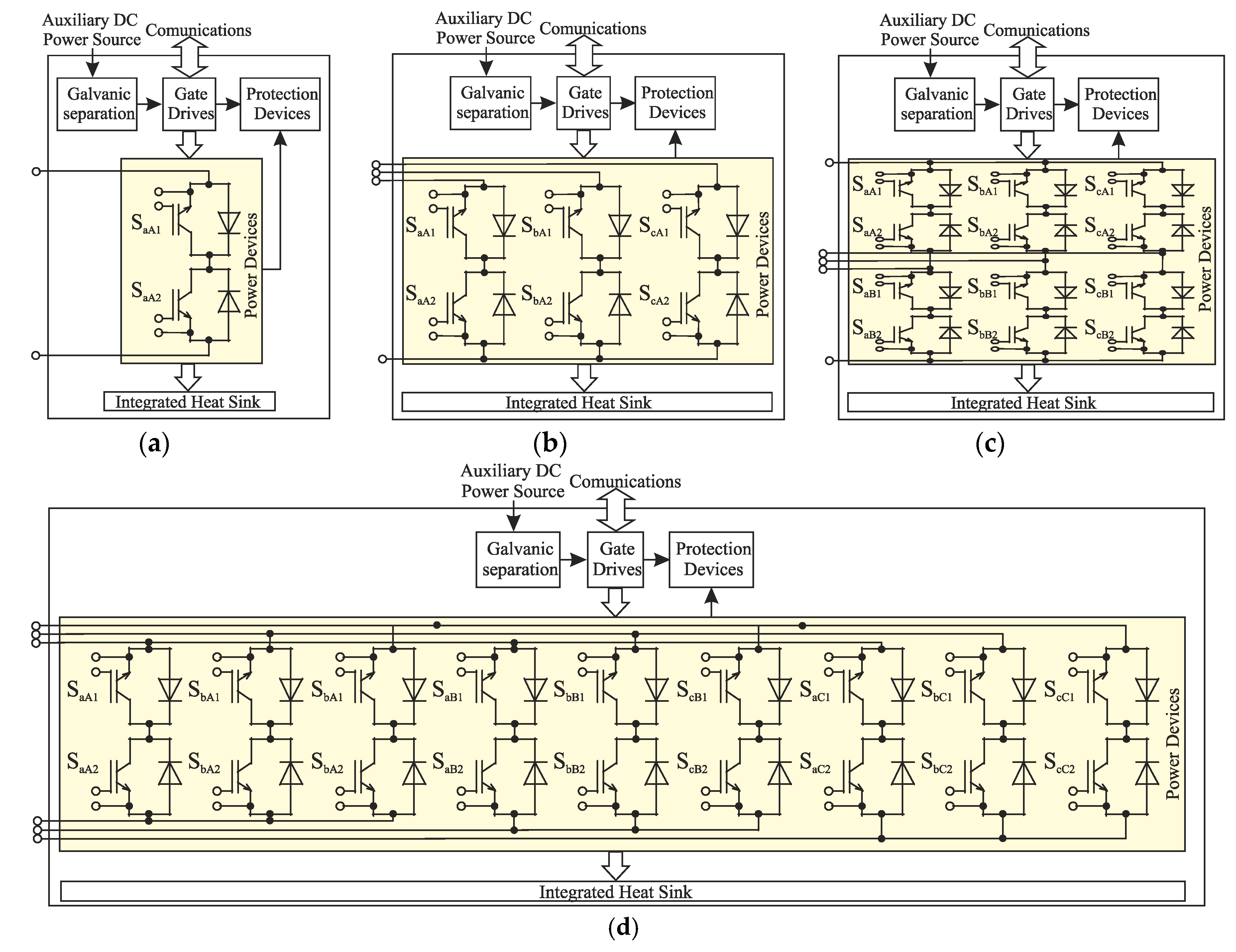
In the analyzed AC/AC power converters, depending on the topology, there are several basic blocks presented in Figure 15. Figure 15a is the most widely used single bidirectional switch structure, which consists of two active switches and two diodes anti-parallel with them. Practical implementation of such a basic block can be realized by using power electronic switches with the dedicated driver systems that are shown in Figure 8. Figure 15b shows a basic structure for a single leg of the matrix converter structure. This basic block may be used for the construction of both the classical MC (Figure 4a) as well as the multilevel MC (Figure 14). Two prototypes of power module in such configurations as SML150MAT12 and SML300MAT06 are proposed and presented in Table 1. Another basic block from Figure 15c is the arrangement of a three-to-single phase MC, which can be used in a multilevel MC (Figure 14) or can be operated as a rectifier [39]. The most complex block power is the whole structure of the MC in a single device shown in Figure 15d. Manufacturers of semiconductor power devices offer several of these dedicated structures, as shown in Table 1.
3.6. The Development of Modulation Methods
The development of varied technologies is related to the possibility of following the evolving trends in technology. In this subsection, it is shown that, in the discussed topologies, it is possible to implement recent commonly developed methods of predictive control.
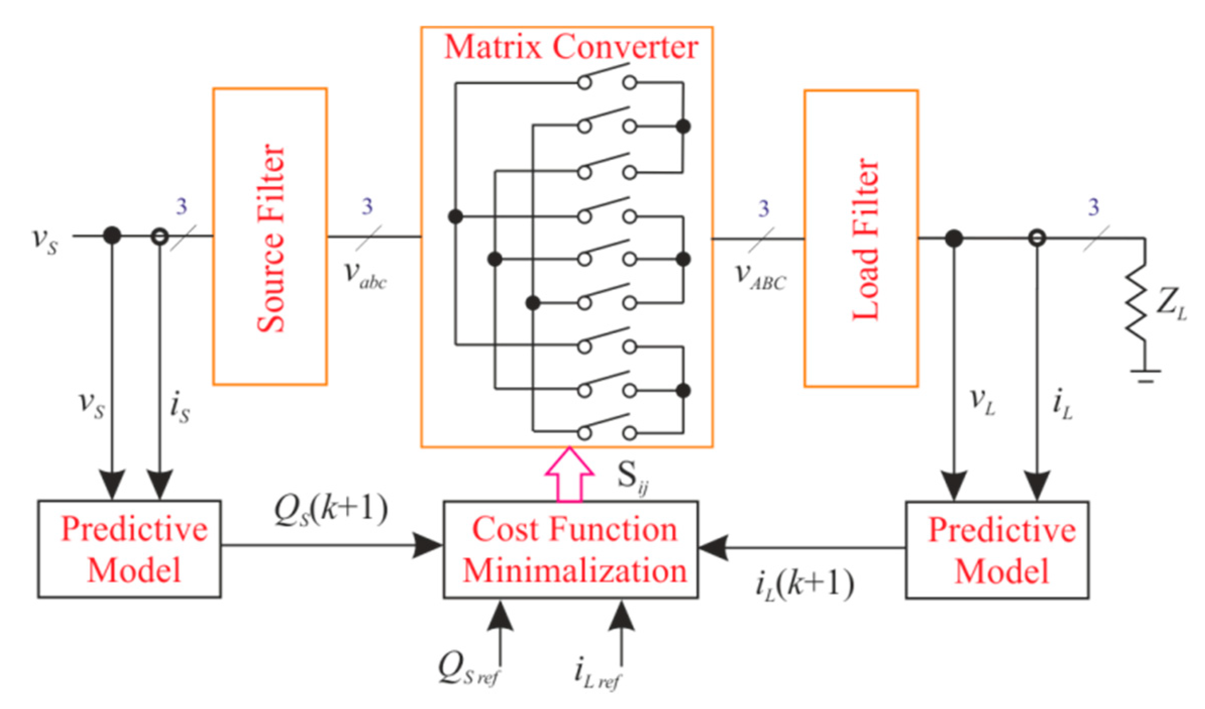
Modulation strategies in AC/AC converters without capacitors in the intermediate circuit are not a simple issue due to the high number of transistors. AC/AC choppers have much simpler modulation strategies. Most modulation techniques have been determined for classical, direct MCs, and they are presented in a review article [22]. In recent years, MPC has been the best developed method of modulation. At discrete time Td, MPC examines a model of a controlled system and predicts its condition in the next step. The configuration of converter switches is selected to ensure a minimum value of the cost function [40]. Scientific publications with MPC of an MC show better achievements in the quality of current and voltage waveforms, torque ripple, and internal switching power losses [30,41,42]. An example MPC scheme for the MC is shown in Figure 16, and this example is one that minimizes the cost function related to the accuracy of shaping the output current and the input power factor. Development of predictive control methods in AC systems without DC-link capacitors is a future area of extensive conceptual and implementation research.
The AC/AC chopper modulation algorithms are not complicated and are based only on the change in the control pulse duty factor. Research on control algorithms is mainly related to increasing efficiency, identifying faults, and optimizing their operation during component failures. New system structures are also being developed that produce significantly better properties regarding efficiency and power density [43,44].
4. Novel Applications of AC/AC Converters without DC-Link Capacitor
The classic application of frequency converters such as the matrix converter is to variable speed electric drives, while the AC/AC choppers are used in applications such as industrial process heating, the control of lighting intensity, or the soft-start of an induction AC motor. These applications are ubiquitously described in the literature and will not be analyzed in this article.
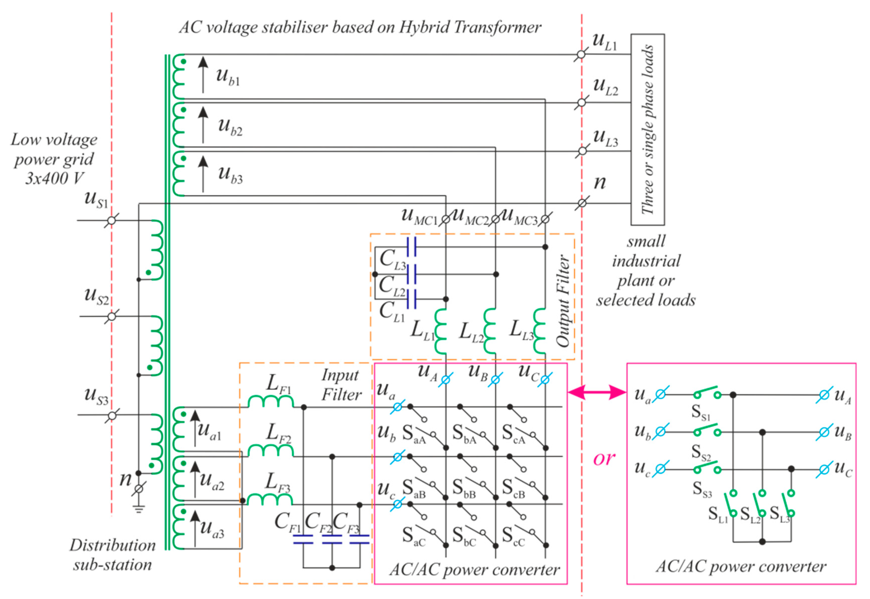
New potential areas for the application of choppers and AC/AC frequency converters without a DC-link circuit are in such devices as compensators for voltage fluctuations in the electric power grid and power flow controllers [19,45,46]. An example of such a compensator with a power flow control function is the hybrid transformer (HT) with a matrix converter or a matrix chopper [45,46], which is shown in Figure 17. The HT contains two main units: (1) a conventional three-phase transformer with two pairs of secondary windings and (2) a three-phase AC/AC converter. The first pair of output windings supplies the converter, whereas the second pair is connected in series with the output terminals of the converter. The compensating voltage is generated at the output of the converter. The output voltage of the whole HT is the sum of the power converter output voltage and the second secondary winding voltage of the transformer. The output terminals of the HT are connected with a sensitive load or a protected small industrial plant. The disadvantage of the HT is the necessity of using transformers with two pairs of secondary windings. Furthermore, under normal supply voltage conditions, the inverter can be switched off, resulting in this part of the transformer generating additional power losses.
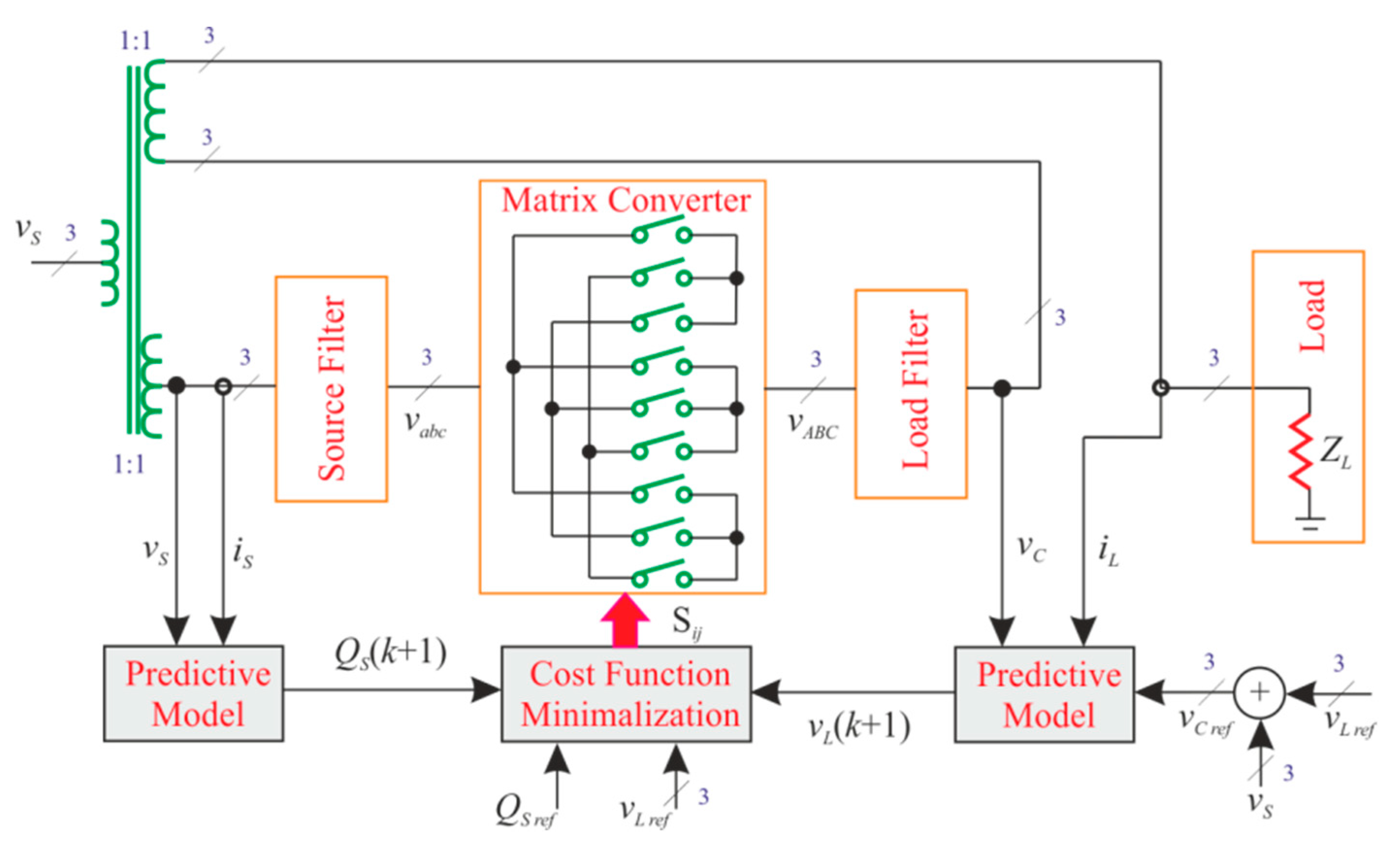
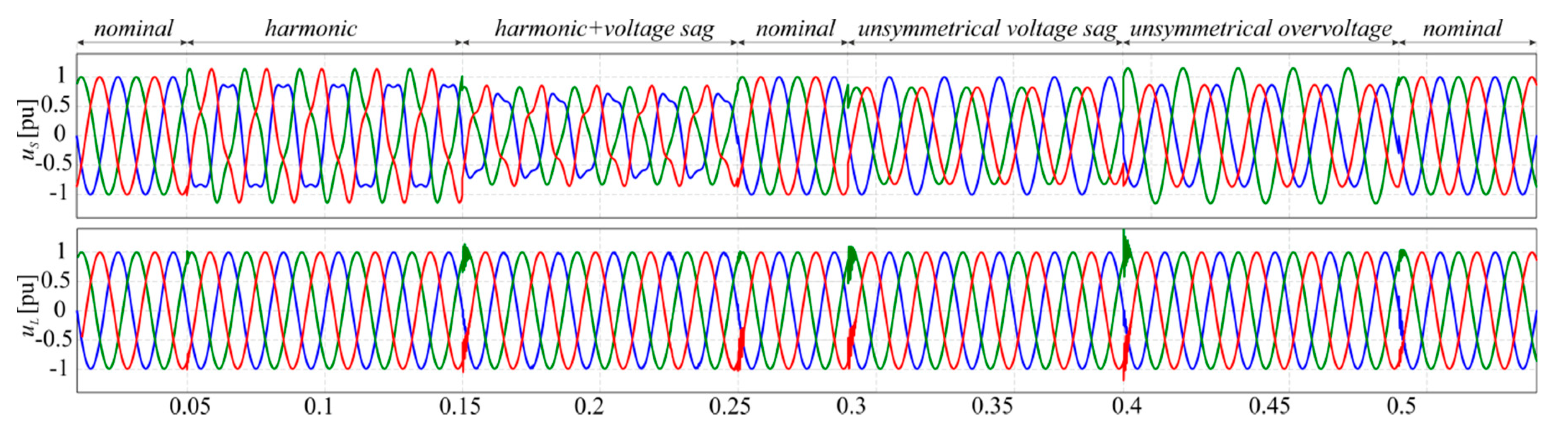
A hybrid transformer with a matrix chopper allows compensation only for the amplitude of the supply voltage; using a matrix converter, it is possible to compensate for both symmetrical and asymmetrical voltage changes as well as harmonic distortions. As an example, to illustrate the beneficial properties of an HT with an MC, the results of the MPC algorithm (Figure 18) are presented in Figure 19 [47]. As can be seen from Figure 19, the output voltage of the compensator is kept at a constant amplitude with no harmonic distortion, despite large fluctuations in the main voltage.
If such an HT were connected to a dual-source network, it would be possible to regulate the power flow in the system by changing the phase angle of the compensator output voltage [46]. As can be seen from the above applications, AC/AC converters without a DC-link capacitor can be used in non-standard applications in low voltage power grids.
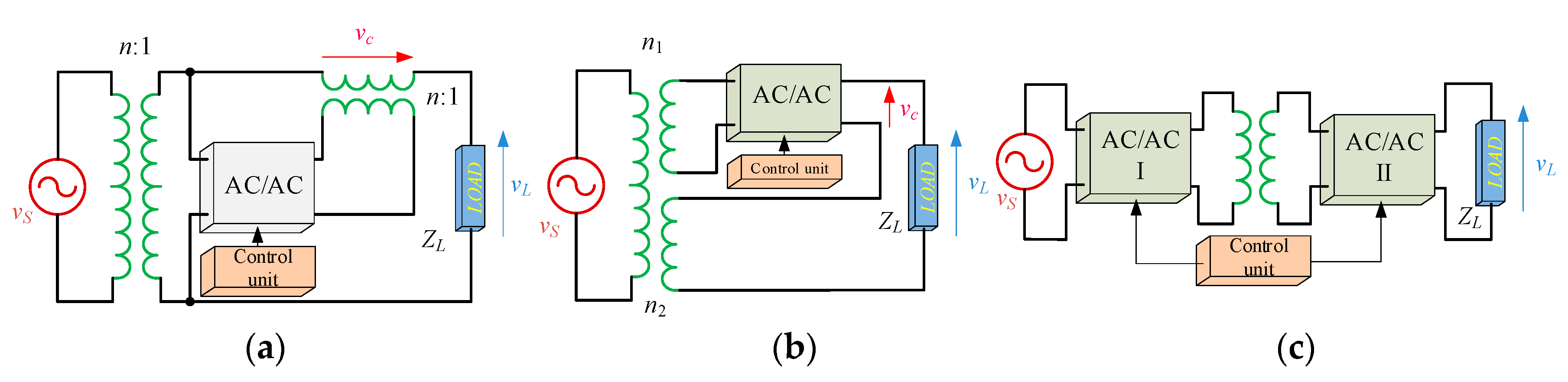
The main requirements for devices installed in the power system are a high reliability and a high efficiency factor. For an AC/AC converter, the parts most sensitive to damage are the power electronic elements. The installed converters should permit continuous work even after the occurrence of a fault in the power electronic converter, ensuring greater reliability. The reliability is high if the load can work with source voltage parameters (or slightly modified) even when damage has occurred in the power electronic part [19]. In this case, the bypass circuits should be used to disconnect or short-circuit the defective converter. In Figure 20, the single phase equivalent models of example AC/AC converters without a DC-link capacitor installed in the power system are presented. In the case of damage to the power electronic unit (AC/AC), the topologies based on the configuration shown in Figure 20a,b, could still operate with source (vS) parameters, after activation of the additional bypass switch. In the case of the configuration shown in Figure 20c, the reliability can be assessed as low. In the event of damage to the AC/AC converter, the whole circuit must be turned off, because it is unable to continue to operate. As a result, all receivers connected to the load side have to be shut off.
5. Conclusions
The presented converter offers a number of important benefits. However, such devices are still not widely used. Their application at the industrial level has been halted due to the fact that there are a number of challenges that must be overcome. This article has identified the challenges faced by the designers of such systems. The main aim of this article was to identify the problems that need to be addressed by research to enable the use of such converters without DC energy storage elements.
The main barrier to the development of AC/AC converters is due to the small number of available semiconductor power components. In addition, there are virtually no solutions in the form of intelligent modules that also include gate drivers and systems providing additional measuring and protection functions. It should be pointed out that minimizing the size of AC/AC converters without a DC-link circuit will become possible as a result of the development of modules which will be dedicated and optimized in terms of functionality, size, and performance of intelligent power modules. Another constraint is met in the complex algorithms for the modulation and commutation of transistors, which requires the construction of complex systems most often equipped with DSP and FPGA. In addition, the complexity of the above-mentioned algorithms also involves the use of additional electronic circuits, such as current flow detectors or a clamp protection circuit.
Finally, the article identifies the application possibilities of the analyzed topologies in modern power systems. The potential of modern control algorithms based on MPC has also been indicated. Comparative analysis shows that the use of such algorithms produces very good properties in voltage or current signal shapes.
Funding
This research received no external funding.
Conflicts of Interest
The authors declare no conflict of interest.
References
- Yang, Y.; Wang, H.; Sangwongwanich, A.; Blaabjerg, F. Design for Reliability of Power Electronic Systems. In Power Electronics Handbook, 4th ed.; Butterworth-Heinemann: Oxford, UK, 2018; pp. 1423–1440. [Google Scholar]
- Chung, H.S.-H.; Wang, H.; Blaabjerg, F.; Pecht, M. Reliability of Power Electronic Converter Systems; The Institution of Engineering and Technology: London, UK, 2015. [Google Scholar]
- Sang, Z.; Mao, C.; Lu, J.; Wang, D. Analysis and Simulation of Fault Characteristics of Power Switch Failures in Distribution Electronic Power Transformers. Energies 2013, 6, 4246–4268. [Google Scholar] [CrossRef]
- Fischer, K.; Pelka, K.; Puls, S.; Poech, M.-H.; Mertens, A.; Bartschat, A.; Tegtmeier, B.; Broer, C.; Wenske, J. Exploring the Causes of Power-Converter Failure in Wind Turbines based on Comprehensive Field-Data and Damage Analysis. Energies 2019, 12, 593. [Google Scholar] [CrossRef]
- Choi, U.M.; Blaabjerg, F.; Lee, K.B. Study and Handling Methods of Power IGBT Module Failures in Power Electronic Converter Systems. IEEE Trans. Power Electron. 2015, 30, 2517–2533. [Google Scholar] [CrossRef]
- Kamel, T.; Biletskiy, Y.; Chang, L. Fault Diagnoses for Industrial Grid-Connected Converters in the Power Distribution Systems. IEEE Trans. Ind. Electron. 2015, 62, 6496–6507. [Google Scholar] [CrossRef]
- Peftitsis, D.; Rabkowski, J. Gate and Base Drivers for Silicon Carbide Power Transistors: An Overview. IEEE Trans. Power Electron. 2016, 31, 7194–7213. [Google Scholar] [CrossRef]
- Marzoughi, A.; Burgos, R.; Boroyevich, D. Characterization and Performance Evaluation of the State-of-the-Art 3.3 kV 30 A Full-SiC MOSFETs. IEEE Trans. Ind. Appl. 2019, 55, 575–583. [Google Scholar] [CrossRef]
- Zhang, L.; Yuan, X.; Wu, X.; Shi, C.; Zhang, J.; Zhang, Y. Performance Evaluation of High-Power SiC MOSFET Modules in Comparison to Si IGBT Modules. IEEE Trans. Power Electron. 2019, 34, 1181–1196. [Google Scholar] [CrossRef]
- Jones, E.A.; Wang, F.F.; Costinett, D. Review of Commercial GaN Power Devices and GaN-Based Converter Design Challenges. IEEE J. Emerg. Sel. Top. Power Electron. 2016, 4, 707–719. [Google Scholar] [CrossRef]
- Wang, H.; Blaabjerg, F. Reliability of capacitors for DC-Link applications in power electronic converters—An overview. IEEE Trans. Ind. Appl. 2014, 50, 3569–3578. [Google Scholar] [CrossRef]
- Yun, G.; Cho, Y. Active Hybrid Solid State Transformer Based on Multi-Level Converter Using SiC MOSFET. Energies 2019, 12, 66. [Google Scholar] [CrossRef]
- Zhu, Q.; Dai, W.; Guan, L.; Tan, L.; Li, Z.; Xie, D. A Fault-Tolerant Control Strategy of Modular Multilevel Converter with Sub-Module Faults Based on Neutral Point Compound Shift. Energies 2019, 12, 876. [Google Scholar] [CrossRef]
- Volosencu, C. System Reliability; Intech Open: Rijeka, Croatia, 2017. [Google Scholar]
- Kolar, J.W.; Friedli, T.; Rodriguez, J.; Wheeler, P.W. Review of three-phase PWM AC–AC converter topologies. IEEE Trans. Ind. Electron. 2011, 58, 4988–5006. [Google Scholar] [CrossRef]
- Szcześniak, P.; Kaniewski, J.; Jarnut, M. AC/AC power electronic converters without DC energy storage: A review. Energy Convers. Manag. 2015, 92, 483–497. [Google Scholar] [CrossRef]
- Zhang, J.; Li, L.; Dorrell, D.G. Control and applications of direct matrix converters: A review. Chin. J. Electr. Eng. 2018, 4, 18–27. [Google Scholar]
- Empringham, L.; Kolar, J.W.; Rodriguez, J.; Wheeler, P.W.; Clare, J.C. Technological issues and industrial application of matrix converters: A review. IEEE Trans. Ind. Electron. 2013, 60, 4260–4271. [Google Scholar] [CrossRef]
- Kaniewski, J.; Fedyczak, Z.; Szcześniak, P. AC voltage transforming circuits in power systems. Electr. Rev. 2015, 91, 8–17. [Google Scholar]
- Kaniewski, J.; Szcześniak, P.; Jarnut, M.; Benysek, G. Hybrid voltage sag/swell compensator. A review of AC/AC converters. IEEE Ind. Electron. Mag. 2015, 9, 37–48. [Google Scholar] [CrossRef]
- Szcześniak, P.; Kaniewski, J. Power electronics converters without DC energy storage in the future electrical power network. Electr. Power Syst. Res. 2015, 129, 194–207. [Google Scholar] [CrossRef]
- Andreu, J.; Kortabarria, I.; Ormaetxea, E.; Ibarra, E.; Martin, J.L.; Apiñaniz, S. A step forward towards the development of reliable matrix converters. IEEE Trans. Ind. Electron. 2012, 59, 167–183. [Google Scholar] [CrossRef]
- Rodriguez, J.; Rivera, M.; Kolar, J.W.; Wheeler, P.W. A review of control and modulation methods for matrix converters. IEEE Trans. Ind. Electron. 2012, 59, 58–70. [Google Scholar] [CrossRef]
- Safari, S.; Castellazzi, A.; Wheeler, P. Experimental and Analytical Performance Evaluation of SiC Power Devices in the Matrix Converter. IEEE Trans. Power Electron. 2014, 29, 2584–2596. [Google Scholar] [CrossRef]
- Empringham, L.; de Lillo, L.; Schulz, M. Design Challenges in the Use of Silicon Carbide JFETs in Matrix Converter Applications. IEEE Trans. Power Electron. 2014, 29, 2563–2573. [Google Scholar] [CrossRef]
- Trentin, A.; de Lillo, L.; Empringham, L.; Wheeler, P.; Clare, J. Experimental Comparison of a Direct Matrix Converter Using Si IGBT and SiC MOSFETs. IEEE J. Emerg. Sel. Top. Power Electron. 2015, 3, 542–554. [Google Scholar] [CrossRef]
- Trentin, A.; Empringham, L.; de Lillo, L.; Zanchetta, P.; Wheeler, P.; Clare, J. Experimental Efficiency Comparison Between a Direct Matrix Converter and an Indirect Matrix Converter Using Both Si IGBTs and SiC mosfets. IEEE Trans. Ind. Appl. 2016, 52, 4135–4145. [Google Scholar] [CrossRef]
- Buccella, C.; Cecati, C.; Latafat, H. Digital Control of Power Converters—A Survey. IEEE Trans. Ind. Inform. 2012, 8, 437–447. [Google Scholar] [CrossRef]
- Kobravi, K.; Iravani, R.; Kojori, H.A. Three-Leg/Four-Leg Matrix Converter Generalized Modulation Strategy—Part II: Implementation and Verification. IEEE Trans. Ind. Electron. 2013, 60, 860–872. [Google Scholar] [CrossRef]
- Gulbudak, O.; Santi, E. FPGA-Based Model Predictive Controller for Direct Matrix Converter. IEEE Trans. Ind. Electron. 2016, 63, 4560–4570. [Google Scholar] [CrossRef]
- Wiśniewski, R.; Bazydło, G.; Szcześniak, P.; Wojnakowski, M. Petri Net-Based Specification of Cyber-Physical Systems Oriented to Control Direct Matrix Converters with Space Vector Modulation. IEEE Access 2019, 7, 23407–23420. [Google Scholar] [CrossRef]
- Yamamoto, E.; Hara, H.; Uchino, T.; Kawaji, M.; Kume, T.J.; Kang, J.-K.; Krug, H.-P. Development of MCs and its Applications in Industry. IEEE Ind. Electron. Mag. 2011, 5, 4–12. [Google Scholar] [CrossRef]
- Oancea, C.D.; Dinu, C. LEM transducers interface for voltage and current monitoring. In Proceedings of the 9th International Symposium on Advanced Topics in Electrical Engineering (ATEE’15), Bucharest, Romania, 7–9 May 2015; pp. 949–952. [Google Scholar]
- Sozański, K. Digital Signal Processing in Power Electronics Control Circuits, 2nd ed.; Springer: London, UK, 2017. [Google Scholar]
- Bobrowska-Rafal, M.; Rafal, K.; Jasinski, M.; Kazmierkowski, M.P. Grid synchronization and symmetrical components extraction with PLL algorithm for grid connected power electronic converters—A review. Bull. Pol. Acad. Sci. Tech. Sci. 2011, 59, 485–497. [Google Scholar] [CrossRef]
- Irmak, E.; Colak, I.; Kaplan, O.; Guler, N. Design and application of a novel zero-crossing detector circuit. In Proceedings of the International Conference on Power Engineering, Energy and Electrical Drives, Malaga, Spain, 11–13 May 2011. [Google Scholar]
- Iyer, A.R.; Kandula, R.P.; Moghe, R.; Hernandez, J.E.; Lambert, F.C.; Divan, D. Validation of the Plug-and-Play AC/AC Power Electronics Building Block (AC-PEBB) for Medium-Voltage Grid Control Applications. IEEE Trans. Ind. Appl. 2014, 50, 3549–3557. [Google Scholar] [CrossRef]
- Laka, A.; Barrena, J.A.; Chivite-Zabalza, J.; Rodriguez, M.A. Analysis and Improved Operation of a PEBB-Based Voltage-Source Converter for FACTS Applications. IEEE Trans. Power Deliv. 2013, 28, 1330–1338. [Google Scholar] [CrossRef]
- You, K.; Xiao, D.; Rahman, M.F.; Uddin, M.N. Applying Reduced General Direct Space Vector Modulation Approach of AC/AC Matrix Converter Theory to Achieve Direct Power Factor Controlled Three-Phase AC-DC Matrix Rectifier. IEEE Trans. Ind. Appl. 2014, 50, 2243–2257. [Google Scholar] [CrossRef]
- Rodríguez, J.; Cortes, P. Predictive Control of Power Converters and Electrical Drives; John Wiley & Sons: Hoboken, NJ, USA, 2012. [Google Scholar]
- Zhang, J.; Norambuena, M.; Li, L.; Dorrell, D.; Rodriguez, J. Sequential Model Predictive Control of Three-Phase Direct Matrix Converter. Energies 2019, 12, 214. [Google Scholar] [CrossRef]
- Rivera, M.; Rojas, C.; Rodriguez, J.; Wheeler, P.W.; Wu, B.; Espinoza, J.R. Predictive Current Control with Input Filter Resonance Mitigation for a Direct Matrix Converter. IEEE Trans. Power Electron. 2011, 26, 2794–2803. [Google Scholar] [CrossRef]
- Khan, A.A.; Cha, H.; Ahmed, H.F. High-Efficiency Single-Phase AC–AC Converters Without Commutation Problem. IEEE Trans. Power Electron. 2016, 31, 5655–5665. [Google Scholar] [CrossRef]
- Khan, A.A.; Cha, H.; Kim, H. Three-Phase Three-Limb Coupled Inductor for Three-Phase Direct PWM AC–AC Converters Solving Commutation Problem. IEEE Trans. Ind. Electron. 2016, 63, 189–201. [Google Scholar] [CrossRef]
- Kaniewski, J.; Fedyczak, Z.; Benysek, G. AC voltage sag/swell compensator based on three-phase hybrid transformer with buck-boost matrix-reactance chopper. IEEE Trans. Ind. Electron. 2014, 61, 3835–3846. [Google Scholar] [CrossRef]
- Szcześniak, P.; Kaniewski, J. Hybrid transformer with matrix converter. IEEE Trans. Power Deliv. 2016, 31, 1388–1396. [Google Scholar] [CrossRef]
- Szcześniak, P.; Tadra, T.; Kaniewski, J.; Fedyczak, Z. Model predictive control algorithm of AC voltage stabilizer based on hybrid transformer with a matrix converter. Electr. Power Syst. Res. 2019, 170, 222–228. [Google Scholar] [CrossRef]
Figure 1.
Two-level back-to-back converter with DC-link.

Figure 2.
Distribution of faults in power electronic converters [14].
Figure 2.
Distribution of faults in power electronic converters [14].

Figure 3.
AC/AC controller: (a) main circuit; (b) voltage time waveforms.

Figure 4.
Matrix converter: (a) main circuit; (b) voltage time waveforms.

Figure 5.
Bi-directional switches: (a) Common emitter IGBT, (b) common collector IGBT, (c) IGBT with a diode bridge, and (d) RB-IGBT reverse blocking IGBTs.
Figure 5.
Bi-directional switches: (a) Common emitter IGBT, (b) common collector IGBT, (c) IGBT with a diode bridge, and (d) RB-IGBT reverse blocking IGBTs.

Figure 6.
MC construction: (a) Dynex 1.2 kV/200 A IGBT; (b) a built-in MC structure in the control cabinet.
Figure 6.
MC construction: (a) Dynex 1.2 kV/200 A IGBT; (b) a built-in MC structure in the control cabinet.

Figure 7.
Matrix-connected RB-IGBTs module: (a) photograph; (b) topology structure.

Figure 8.
A photograph of the IGBTs with dedicated drivers: (a) Dynex IGBT with Concept driver; (b,c) Semicron drivers and IGBTs.
Figure 8.
A photograph of the IGBTs with dedicated drivers: (a) Dynex IGBT with Concept driver; (b,c) Semicron drivers and IGBTs.

Figure 9.
Main topologies for SiC bi-directional switches: (a) common drain anti-paralleled JFET, (b) common source anti-paralleled SiC MOSFET, and (c) common emitter anti-paralleled SiC BJT.
Figure 9.
Main topologies for SiC bi-directional switches: (a) common drain anti-paralleled JFET, (b) common source anti-paralleled SiC MOSFET, and (c) common emitter anti-paralleled SiC BJT.

Figure 10.
Illustration of the beneficial properties of the use of SiC transistors, taken from [24], presents the efficiency of a two-phase to single-phase 2.5 kW MC in Si and SiC technology (a) as a function of switching frequency at Tc = 125 °C and (b) as a function of power at fs = 100 kHz, Tc = 125 °C.

Figure 11.
Distribution of control pulses in a single period of the control sequence TSeq: (a) in the phase leg of a matrix converter, (b) in the phase leg of a classical inverter.
Figure 11.
Distribution of control pulses in a single period of the control sequence TSeq: (a) in the phase leg of a matrix converter, (b) in the phase leg of a classical inverter.

Figure 12.
Four-step commutation process in one output phase of the MC: (a) switching diagram; (b) control signals from FPGA devices.
Figure 12.
Four-step commutation process in one output phase of the MC: (a) switching diagram; (b) control signals from FPGA devices.


Figure 13.
Circuit diagram of the zero-crossing detector.

Figure 14.
Multilevel, medium voltage matrix converters: (a) a multilevel MC with nine basic power switch blocks; (b) a three-phase to single-phase (3 × 2) MC power block.
Figure 14.
Multilevel, medium voltage matrix converters: (a) a multilevel MC with nine basic power switch blocks; (b) a three-phase to single-phase (3 × 2) MC power block.

Figure 15.
Common switching structures for power-electronic building blocks (PEBBs) in AC/AC power converters (a) single bidirectional switch structure, (b) single output phase of MC switch configuration, (c) two phase of MC switch configuration, (d) three phase of MC switch configuration.
Figure 15.
Common switching structures for power-electronic building blocks (PEBBs) in AC/AC power converters (a) single bidirectional switch structure, (b) single output phase of MC switch configuration, (c) two phase of MC switch configuration, (d) three phase of MC switch configuration.

Figure 16.
Model predictive control (MPC) of an MC with minimalization of the output current ripples and input power factor (reactive power).
Figure 16.
Model predictive control (MPC) of an MC with minimalization of the output current ripples and input power factor (reactive power).

Figure 17.
Compensator for voltage fluctuations, based on the HT with an MC or matrix chopper, installed at connection terminals of an industrial plant, a building, or selected industrial loads.
Figure 17.
Compensator for voltage fluctuations, based on the HT with an MC or matrix chopper, installed at connection terminals of an industrial plant, a building, or selected industrial loads.

Figure 18.
MPC of an HT voltage compensator with an MC and minimalization of the output voltage tracking error and input power factor.
Figure 18.
MPC of an HT voltage compensator with an MC and minimalization of the output voltage tracking error and input power factor.

Figure 19.
Results of compensations of electric power grid voltage fluctuation using an HT with an MC and MPC control (author’s simulation results); red – voltage phase 1, blue – voltage phase 2, green – voltage phase 3.
Figure 19.
Results of compensations of electric power grid voltage fluctuation using an HT with an MC and MPC control (author’s simulation results); red – voltage phase 1, blue – voltage phase 2, green – voltage phase 3.

Figure 20.
Single phase equivalent models of AC/AC converters installed in the power grid, (a,b) high reliability configurations, (c) low reliability configuration.
Figure 20.
Single phase equivalent models of AC/AC converters installed in the power grid, (a,b) high reliability configurations, (c) low reliability configuration.


Table 1.
Available, selected commercial modules with bidirectional switches.
| Switch Model | Characteristic | Manufacturer | Number of Bidirectional Switches |
|---|---|---|---|
| DIM200MBS12-A | 1.2 kV/200 A | DYNEX | 1 |
| DIM400PBM17-A | 1.7 kV/400 A | DYNEX | 1 |
| DIM600EZM17-E | 1.7 kV/600 A | DYNEX | 1 |
| SK 60GM123 | 1.7 kV/60 A | SEMICRON | 1 |
| SKM 150GM12T4G | 1.2 kV/60 A | SEMICRON | 1 |
| SML150MAT12 | 1.2 kV/150 A | SEMELAB | 3 |
| SML300MAT06 | 0.6 kV/300 A | SEMELAB | 3 |
| 18MBI50W-120A | 1.2 kV/ 50A | FUJI | 9 |
| 18MBI100W-060A | 0.6 kV/100 A | FUJI | 9 |
| 18MBI100W-120A | 1.2 kV/100 A | FUJI | 9 |
| 18MBI200W-060A | 0.6 kV/200 A | FUJI | 9 |
Table 2.
Selected available voltage and current measurement amplifiers and transducers.
| Model | Isolation/Operation | Manufacturer | Type |
|---|---|---|---|
| HCPL-7860 | Optic | Avago Technologies | Current |
| HCPL-786J | Optic | Agilent | Current |
| HCPL-7800 | Optic | Avago Technologies | Current |
| ISO124 | capacitive | Texas Instruments | Current/Voltage |
| ISO120/121 | capacitive | Burr-Brown Corporation | Current/Voltage |
| INA270 | difference amplifier | Texas Instruments | Current |
| LM358 | difference amplifier | Texas Instruments | Current |
| AD8210 | difference amplifier | Analog Devices | Current. |
| ACS752SCA-100 | magnetic | Allegro MicroSystems | Current |
| ACS756xCB | magnetic | Allegro MicroSystems | Current |
| LV-25 | magnetic | LEM | Voltage |
| LTS 25-NP | magnetic | LEM | Current |
| MP25P1 | magnetic | ABB | Current |
| VS500B | magnetic | ABB | Voltage |
© 2019 by the author. Licensee MDPI, Basel, Switzerland. This article is an open access article distributed under the terms and conditions of the Creative Commons Attribution (CC BY) license (http://creativecommons.org/licenses/by/4.0/).
Share and Cite
MDPI and ACS Style
Szczesniak, P. Challenges and Design Requirements for Industrial Applications of AC/AC Power Converters without DC-Link. Energies 2019, 12, 1581. https://0-doi-org.brum.beds.ac.uk/10.3390/en12081581
AMA Style
Szczesniak P. Challenges and Design Requirements for Industrial Applications of AC/AC Power Converters without DC-Link. Energies. 2019; 12(8):1581. https://0-doi-org.brum.beds.ac.uk/10.3390/en12081581
Chicago/Turabian StyleSzczesniak, Pawel. 2019. "Challenges and Design Requirements for Industrial Applications of AC/AC Power Converters without DC-Link" Energies 12, no. 8: 1581. https://0-doi-org.brum.beds.ac.uk/10.3390/en12081581
Note that from the first issue of 2016, this journal uses article numbers instead of page numbers. See further details here.