Article

Wood Chip Drying through the Using of a Mobile Rotary Dryer

1
Consiglio per la ricerca in agricoltura e l’analisi dell’economia agraria (CREA)—Centro di ricerca Ingegneria e Trasformazioni agroalimentari (CREA-IT)—Via della Pascolare 16, 00015 Monterotondo (Rome), Italy
2
National Research Council of Italy, Insitute of Atmospheric Pollution Research, via Salaria km 29,300, 00015 Monterotondo (RM), Italy
*
Author to whom correspondence should be addressed.
Submission received: 19 March 2019 / Revised: 16 April 2019 / Accepted: 17 April 2019 / Published: 26 April 2019

Abstract

:
Drying is a critical point for the exploitation of biomass for energy production. High moisture content negatively affects the efficiency of power generation in combustion and gasification systems. Different types of dryers are available however; it is known that rotary dryers have low cost of maintenance and consume 15% and 30% less in terms of specific energy. The study analyzed the drying process of woody residues using a new prototype of mobile rotary dryer cocurrent flow. Woodchip of poplar (Populus spp.), black locust (Robinia pseudoacacia L.), and grapevine (Vitis vinifera L.) pruning were dried in a rotary drier. The drying cycle lasted 8 h for poplar, 6 h for black locust, and 6 h for pruning of grapevine. The initial biomass had a moisture content of around 50% for the poplar and around 30% for grapevine and black locust. The study showed that some characteristics of the biomass (e.g., initial moisture content, particle size distribution, bulk density) influence the technical parameters (i.e., airflow temperature, rate, and speed) of the drying process and, hence, the energy demand. At the end of the drying process, 17% of water was removed for poplar wood chips and 31% for grapevine and black locust wood chips. To achieve this, result the three-biomass required 1.61 (poplar), 0.86 (grapevine), and 1.12 MJ kgdry solids−1 (black locust), with an efficiency of thermal drying (η) respectively of 37%, 12%, and 27%. In the future, the results obtained suggest an increase in the efficiency of the thermal insulation of the mobile dryer, and the application of the mobile dryer in a small farm, for the recovery of exhaust gases from thermal power plants.

1. Introduction

The use of biomass for energy purposes is related to its moisture content, availability, and pre-treatments such as the drying process [1].
The moisture content of the biomass used for energy production is a key parameter for the proper management of the power plant or in the densification process [2,3,4,5]. Generally, the wet wood biomass has a moisture content, on a wet basis, higher than 50% [6,7] and the natural drying process hardly lowers the moisture contents under 35% in 3–4 months of storage [8,9]. High moisture content of fuels increases the cost of transport, reduces the combustion efficiency [10], and decreases the potential energy input for steam generation. Consequentely, a reduction in the calorific value of the fuel gas produced in gasification is experienced, with a negative effect on the efficiency of power generation in combustion, gasification systems, and pyrolysis processes [5,11,12]. Concerning human health, higher biomass moisture content causes an increase of CO and VOC emission [7] as well as the formation of carcinogenic compounds from wood combustion [13,14]. The fine particles may be responsible for severe diseases, like invasive pulmonary infections or broncho-pulmonary allergies [15], whereas the larger particles one may have a role in air and soil contamination [16]. Forced hot air drying is a process for the conditioning of biomass (firewood and/or wood chips) which allows increasing the efficiency and flexibility of combustion, transportation, and storage process [17]. It may increase the calorific value, lower the emissions [18] and save fuel [19,20]. The principles of biomass drying can also be applied to increase the time to preserve food [21].
However, the choice of a suitable drying system and drying conditions is critical to achieve the required final moisture content [22,23]. Although the forced drying process is a suitable alternative to natural drying [6], it presents higher production costs. The drying process consumes a significant amount of energy, so it would be very important to implement energy saving strategies to reduce energy consumption during the drying process [24]. This one involves the use of hot and dry air as a drying fluid, fed by a fan with a working temperature which can vary between 20 °C and 100 °C [25]. The process depends on several factors such as the particle size of the biomass [10], the temperature and speed of drying air [26,27] and the temperature inside the container [28]. The drying fluid is characterized by a low relative humidity so that the air-water contact causes the evaporation of free water contained in the pores of the biomass particles, the water bounded in the intercapillary spaces and/or the water adsorbed on the surface of the product [29].
In the case of hot air, the fluid can be introduced inside the system directly through a dedicated thermal system, or by using low-cost or even free heat, co-produced and recovered from cogeneration plants by injecting hot air at 80 °C [25]. Of course, the supply of hot air through a dedicated heat plant or the recovery of thermal waste from cogeneration plants leads to different energetic and economic costs. In this way the share of thermal energy recovered by cogeneration plants, almost always dissipated, can be exploited to dry firewood or wood chips [25].
The most common industrial systems for drying biomass are conveyor dryers, rotary dryers of single or multiple passes, fixed and mobile bed dryers, perforated floor bin dryers, direct and indirect fired rotary dryers, cascade dryers, superheated steam dryers, microwave dryers, fluidized bed dryers, screw conveyor dryers, and flash or pneumatic dryers [5,23,27]. However, it is known that rotary dryers have a low cost of maintenance and consume 15% and 30% less in terms of specific energy that the pneumatic and cascade types, respectively [6]. An exhaustive description of the drying systems is present in Mujumdar [30].
The rotary dryer is the most diffuse system for drying small-sized woody biomass [31,32]. Considering the method of heat transfer, rotary dryers, can be classified as direct, indirect-direct, indirect, and special types [
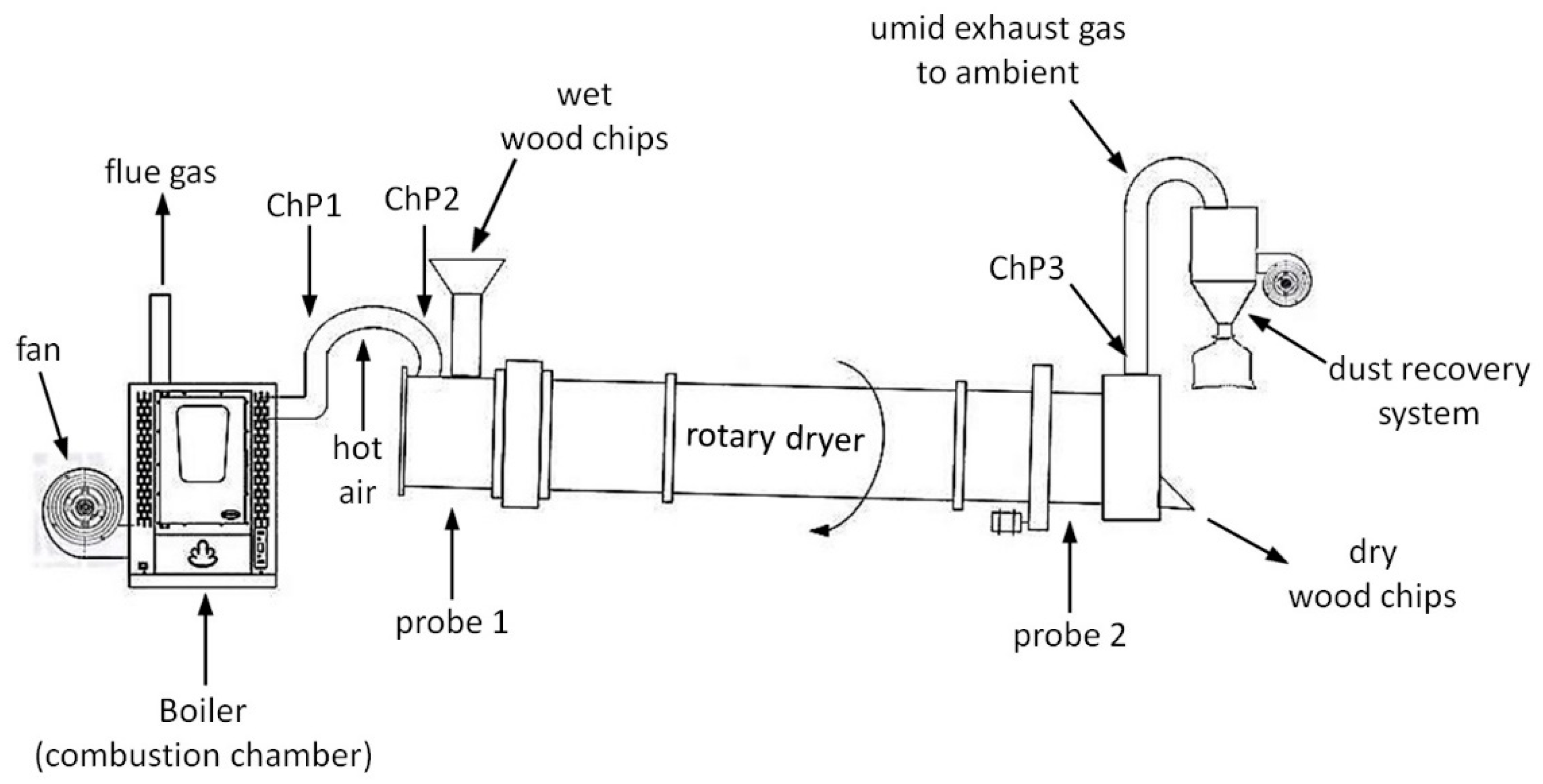
33]. The direct rotary dryers consist of a slightly inclined metal hollow cylinder, rotating around its axis. The internal space is designed to ensure direct contact between the biomass and the drying fluid, usually hot air.
Rotating dryers have the advantage of being less sensitive to particle size and can accept the hottest exhaust gases of any type of dryer. They have lower maintenance costs and greater capacity than any type of dryer. The drying process of the wet biomass in a rotary dryer can be challenging owing to the prolonged time for the uniform drying of the biomass [19], this can also increase the fire hazard inside the dryer [5,18].
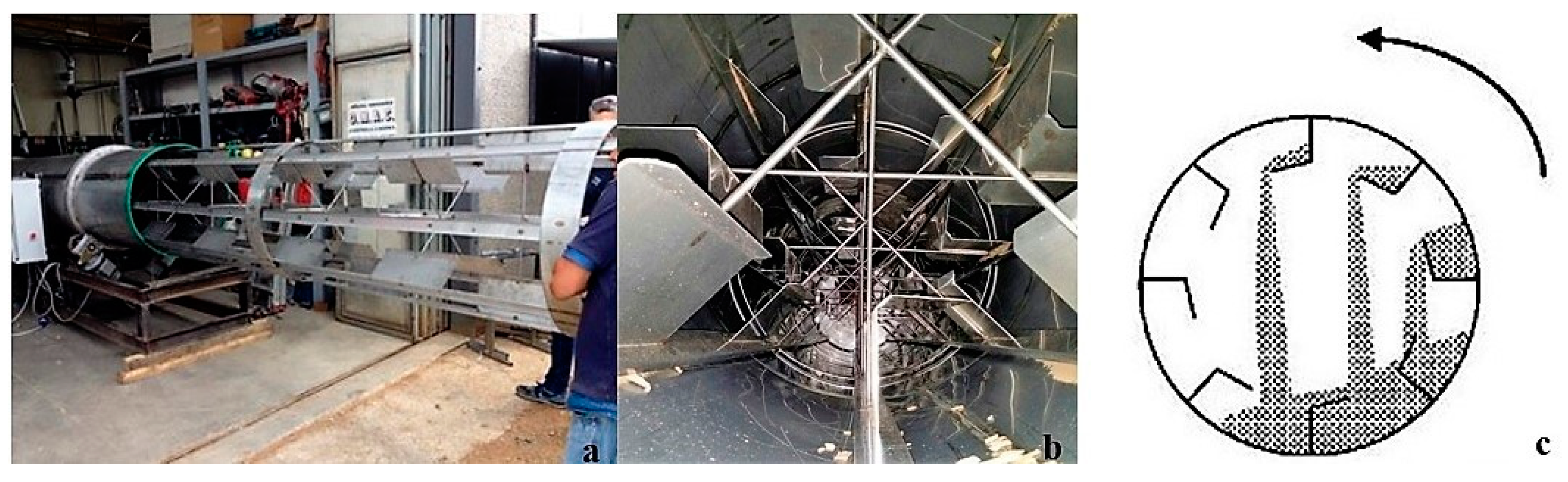
The heat transfer between the hot air and the biomass is improved by a series of flights on the inner surface of the cylinder which serve to increase the contact of the two flows (air/solid). During the rotation, the action of the flights lifts and drops the biomass regularly from top to bottom through the flow of hot air. In this way, each portion of the biomass is invested by the flow of hot air [32,33]. Depending on how the hot air is introduced, there are two types of dryer, cocurrent and countercurrent. In this type of system, the solid fluid (wood chips), kept in constant movement by the rotation of the cylinder, is mixed with the drying fluid (hot air) favouring its drying [31]. A quick drying process reduces considerably the drying time [23], compared to conventional storage methods (piles), in which the natural drying process lasts from 6 to 12 months [18]. If the piles of woodchips are covered with a special fabric, the moisture content can reach about 35% [34]. The energy required to dry 1 kg of wood chips in a rotary dryer is 3.1 MJ [35,36], while the heat needed to evaporate 1 kg of water from wet biomass fuel can exceed 2.6 MJ kg−1 depending on initial and final moisture content and temperature of drying [7]. However, the energy required may vary depending on the type of biomass and the homogeneity of the material [37].
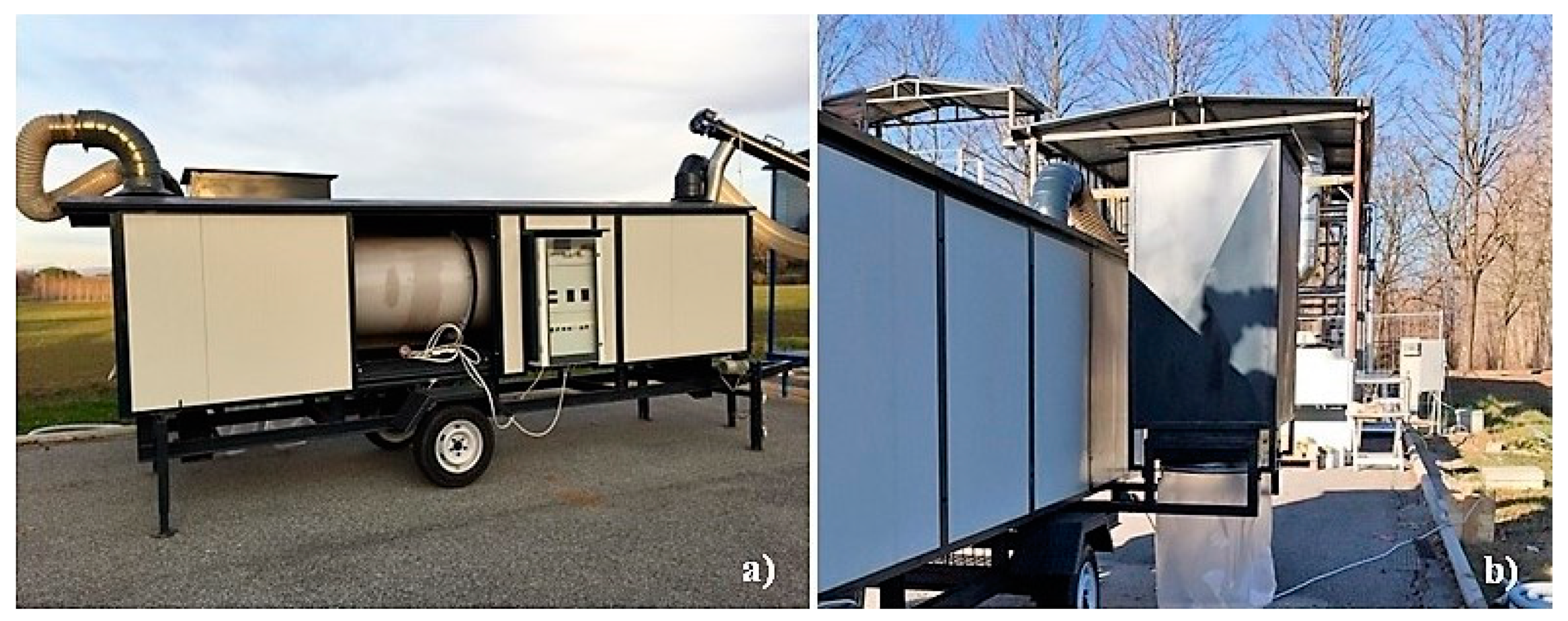
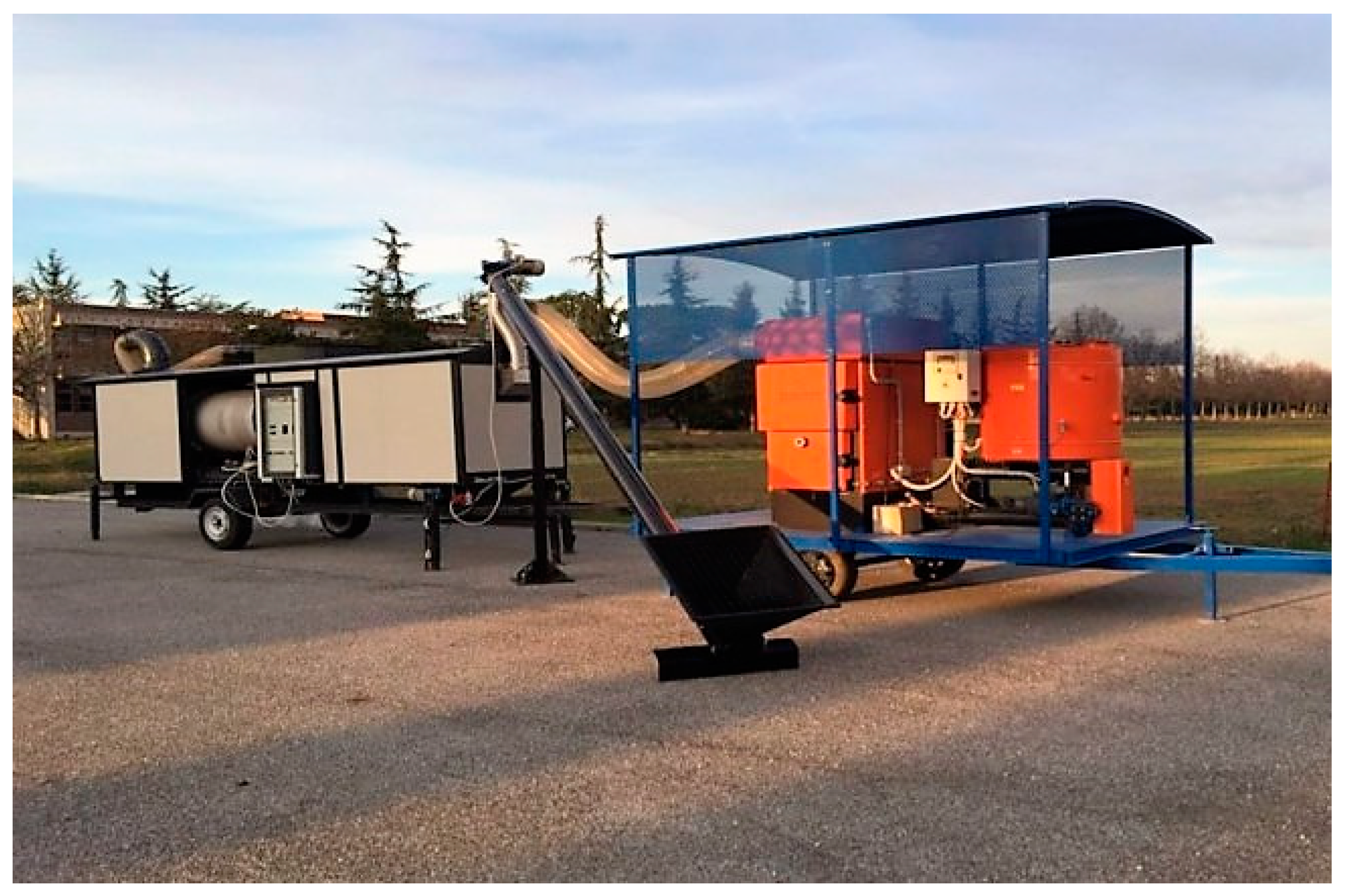
The CREA-IT of Monterotondo (RM) in collaboration with the CNR-IIA tested a new prototype of mobile rotary dryer, for the exploitation of biomass in the field. This preliminary study analyzed the variation of the thermal requirements and the drying profile as a function of the physical characteristics of the biomass. The objective of the study was to evaluate the applicability of the system for the waste heat recovery resulting from combustion plants.

2. Materials and Methods

2.1. Rotary Dryer Prototype

The prototype was a cocurrent rotary dryer with drum designed for wood chips composed of a metallic rotating cylinder of 5 m length and 0.8 m diameter and a volume of 2.5 m3. The cylinder was provided with four openings (Figure 1a): two for the loading and unloading of the product and two for the inlet and outlet of the drying fluid (hot air). The dryer was placed on a mobile floor and was equipped with a system of ventilation of the MZ aspirator (Italy) and dust recovery with two bag filters connected in parallel with a 50 cm diameter, a height of 1 m, and a total dust collection efficiency of 98% (Figure 1b).
The wet biomass was loaded into a hopper equipped with a 150 mm diameter screw conveyor of Pelltech (Germany) for the transport inside the cylinder. Here, the advancement and the subsequent unloading of the biomass was favored by the rotation at 5 revolutions per minute and by an angle of the cylinder of 2° to the horizontal axis.
The rotation of the cylinder was regulated trough an electrical board and a gear reducer. The adjustment of the height occurred trough the setting of two support legs powered by 2 electrics motors. The internal metal structure was provided with flights (48) differently shaped (Figure 2) which favored the mixing of the mass. The set of wings was fixed on a supporting structure, removable from the cylindrical body, which rotates with the drum.
The prototype was connected to a commercial hot air generator of 80 kW (Company D’Alessandro Termomeccanica mod. GSA) through a 250 mm insulated pipe (Figure 3). The generator was equipped with a centrifugal fan, set at a flow rate of about 1100 m3 h−1 (maximum load 5500 m3·h−1) for the diffusion inside the cylinder of a drying fluid at 80 °C. The volume of the hopper for the supply of the hot air generator was 0.19 m3.
The internal temperature of the cylinder was monitored by two k-type termocouples with a thermal range from −60 to 350 °C and a resolution of 0.2 °C; the first positioned at the entry point of the fresh biomass, the second placed at the exit (Figure 4). Both values were displayed on the electric panel. The cylinder was closed inside an insulating structure to limit thermal dispersion and to reduce the risk of contact with hot surfaces.

2.2. Characterization of the Biomass

The characterization of the biomass was carried out at the LAS-ER-B laboratory of CREA-IT in Monterotondo (RM).
The moisture content was monitored at regular intervals of two hours following the European Standard UNI EN 14774-2:2010 [38]. In all tests, three samples of approximately 300 g each were collected in plastic bags, sealed, labeled and transported to the laboratory where they were dried in an oven with forced ventilation for 24 h at 105 ± 2 °C.
The bulk density of the biomass was determined before and after drying, making five weighing with a normalized cylinder of 0.026 m3, according to the requirements of the European standard UNI EN 15103: 2010 [39]. Before the drying tests the analysis of particle size distribution was performed on the incoming biomass (UNI CEN/TS 15149-1:2006 [40]). A representative sample of 12 L was divided into sub-samples of 3 L each, each subsample was analyzed by means of a mechanical sieve shaker of the Fritsch mod. Analysette 18 with normalized sieves according to ISO 3310-2 [41].
The energy content of the biomass referred to a given moisture content (w%), which was calculated with the following Equation (1) [42], referring to the pre and post-drying humidity conditions:
H u ( w ) = H u ( w f ) ×   ( 100 w ) 2.443   ×   w 100
where, Hu(wf): calorific value of the wood dry matter in the “anhydrous” 18.5 MJ kg−1 [43]. w: moisture content of the wet biomass. 2.443 MJ·kg−1: energy required for preheating and evaporation of the water.
The air permeability of the feedstock was calculated following the method reported by Manzone [43] and Pari [44] by means of Equation (2):
A = 19125 (Mean particle size, mm)−0.874
where “A” is a coefficient describing the pressure resistance of the heaped chips to airflow.
As reported by the cited authors, if the mean particle size can be calculated using geometric means, which partly compensate for such skewness towards the lower size classes. The mean particle size is therefore obtained by a weighted average of all particle classes, as represented by their geometric mean calculated with the following Equation (3):
Geometric mean = e^((lnb − lna)/2) + lna)
where a and b are respectively the lower and the upper limits of the given size class.

2.3. Experimental Procedure and Characterization of the Airflow

The feedstock used in the study were woodchip of poplar (Populus spp.), black locust (Robinia pseudoacacia L.), and grapevine (Vitis vinifera L.) pruning. The drying cycle had a constant air flow and lasted 8 h for poplar, 6 h for black locust, and 6 h for pruning of grapevine.
Poplar plants were processed with a chipper FARMI mod. CH 260 to obtain two particle sizes (named Poplar 1 and Poplar 2). The black locust was processed with a drum chipper of the Pezzolato mod. PTH 700/660. The wood chip of grapevine pruning was provided by the company ONG s.n.c. of Castel Bolognese (RA) who made the chipping through the prototype mod. PC50 [45]. The quantities of processed biomass were as follows: 250 kg for both the poplar tests, 207 kg for the black locust, and 144 kg for the grapevine. It should be noted that the pruning of vineyard underwent a preliminary drying in open field for ten days before chipping.
During the tests, biomass sampling was carried out every two hours. Along the system (Figure 4), temperature, rate, and speed of the airflow were measured at three control points (checkpoint, ChP). The first (ChP1) was positioned on the duct conveying the hot air from the boiler to the rotary dryer. It was chosen a point far from the boiler five-fold the diameter of the duct, to avoid the influence of turbulence when reading the data. The second (ChP2) was placed in the same duct immediately before the entrance of the drying fluid in the dryer, while the third (ChP3) corresponded to the output of exhausted fluid from the system. The values of temperature, speed, and rate of the airflow were detected at each ChP with a wire thread anemometer (TSI mod. 9535-A). The temperature inside the cylinder was measured by two probes (Probe 1 and 2) and displayed by the control panel. During the drying process, to optimize economic and environmental performance, the dryer generator was fed with the same dried biomass (Poplar) as was obtained from the dryer [29].

2.4. Energy Analysis

Energy analysis was carried out for assessing the efficiency of the process. To this aim, the thermal energy (Q) needed for drying was calculated applying Equation (4) of Zhou [46]:
Q = M ×   C u   ×   ( Δ T )
where, Q: thermal energy (kJ·h−1). M: drying air flow (kg·h−1). Cu: specific heat of air (J·kg−1·K). ΔT: temperature difference air at the dryer inlet and outlet.
In Equation (4), M is expressed as mass flow, that is, the volumetric flow rate multiplied by the air density (1.03 kg/m3) referred to the working temperature. The following formula is used to determine the amount of heat needed to evaporate moisture from moist woody biomass. The efficiency of thermal drying (η) was calculated as the ratio between the heat used to evaporate the moisture from woody biomass (Q) and the primary energy input (Efuel) in the system, by applying the Equation (5) of Meza [6] and Tippayawong [47]:
η = Q E f u e l

2.5. Statistical Analysis

The data of particle size distribution, bulk density of the biomass before and after drying as well as the thermodynamic parameters were analyzed with the software PAST. After checking the data for normality, the data were subjected to the ANOVA, and the differences tested according to Tukey’s HSD test.
The effect of the specie at different ChP on the drying process was analyzed using the 50-50 MANOVA [48]. The method is a modified variant of classical MANOVA that integrates the Principal Component Analysis (PCA) in its algorithm. The software was applied for the elaboration of PCA. In a PCA, a set of uncorrelated variables (principal components, PCs) is obtained as a linear combination of the original interrelated variables, in such a way that the first PCs explain the largest fraction of the original data variability.

3. Results and Discussion

3.1. Biomass Characterization

Except for grapevine pruning, the amount of dried biomass was above 200 kg (Table 1). The reduced amount used for the grapevine pruning (143.7 kg) was imposed by the physical characteristics of the biomass, because a higher amount would have increased the risk of clogging at the flight system during the movement of the biomass inside the cylinder. During the drying process the deflectors cyclically moved the solid fluid by lifting and dropping it through the drying fluid. In this way the hot air flow blended directly with the wood chips inside the cylinder, and then released its heat. The heat was mostly conveyed during the drop of the product. However, the system presented some losses caused by the contact of the biomass with the cylinder walls, when the heat was transferred by conduction and irradiation [29].
The biomass used in the study showed two levels of moisture content (Table 1): above 50% for poplar and above 30% for grapevine and black locust. This allowed testing of the rotary drier in presence of biomass requiring highly different drying power. The storage period of about 10 days lowered the moisture content of the vineyard chips to 33.3%, while the humidity of the black locust (31.2%) must be considered normal considering the physiological characteristics of the species. In energy plantations, two-year old plants of black locust can show a moisture content close to 45% [49,50] while for older plants the water content ranges between 39% [49] and 32% [3].
It should be noted as the figures confirmed the inverse relationship between moisture content and net calorific value reported by Hellrigl [51]: as the moisture content was much higher the net calorific value was lower. The bulk density of the comminuted biomass decreased with the order black locust > poplar 2 > poplar 1 > grapevine and appeared influenced by the characteristic of the wood morphology rather than the moisture content. Bulk density is a parameter extremely important in handling and storage of biomass because it directly influences the transport costs, the storable amount, the storage conditions, and the final quality of the fuel [52].
The slight difference between the two poplar types probably also reflected the different particle size distribution (Figure 5A). Almost 80% of poplar biomass was concentrated in the classes 3.15–8 mm and 8–16 mm. For these fractions, the difference reached a statistical significance. The fraction 3.15–8 mm accounted for in 37.5% Poplar 2 and 30.1% in Poplar 1, while the fraction 8–16 mm showed an opposite behaviour: higher in Poplar 1 (48.7%) than in Poplar 2 (41.16%).
Such differentiation led to a significant higher mean particle size for Poplar 1 then Poplar 2 and even more to a lower pressure resistance of poplar 1 to air (Table 2).
Unlike poplar, the distributions of the wood chips of grapevine and black locust were shifted towards the longer fractions (Figure 5B), and, both had the highest percentage within the classes 8–16 mm and 16–45 mm. To one side, this has led to the highest mean particle size for grapevine, coupled to the lowest pressure resistance (Table 2). On the other side, the biomass of black locust showed the same characteristics of Poplar 1. The increase in particle size leads to a reduction of the pressure resistance to air, given by the A value [44]. In general, low values mean a good circulation of air and in this specific case, grapevine pruning appeared to be feedstock more prone to facilitating the air movement inside the biomass. In this way, it must be recognized how important it is to achieve the right particle size distribution for woody biomass, because, beside the storage behavior and the handling properties [52], the chip size largely influences the drying speed. Therefore, the comminution phase upwards from the drying process may address to some extent the final result.

3.2. Drying Process

The type of biomass and the characteristics of the drying fluid influenced each other leading to different conditions inside the cylinder and, in turn, to a different pattern of drying (Figure 6A). In eight hours, the moisture content of the Poplar 1 decreased from 54.4% to 43.3%, while the Poplar 2 passed from 52.5% to 34.1%, with a statistically significant difference starting from the fourth hour. The temperature curves inside the cylinder where rather similar, with higher values for Poplar 2 than Poplar 1.
On the other side, after a drying cycle of 6 h the moisture content of the biomass dropped to 15.3% for the grapevine and 11.8% for the black locust (Figure 6B). The two dehydration curves showed a similar trend although in all point of data recording the difference between black locust and the vine pruning residues value was significant. However, these values were obtained with a trend of the temperature inside the cylinder that was completely different with respect to the poplar and between the grapevine and the black locust too. During drying of the grapevine, the temperature inside the cylinder rose from 40 °C to 61 °C while for the black locust it increased from 39 °C to 45 °C.
These results confirm the observations of Kocsis [26] about the influence of the temperature of the drum on the drying rates of biomass. With increasing temperature, the rate and the time required to lower the moisture content decline. The heat provided at the beginning increases the temperature of particles. In our case, this increment was affected by initial moisture content (higher in poplar than in black locust and grapevine) and a higher amount of heat was spent to warm up the particles of poplar. In the following phase, the drying rate of particles was affected only by drying conditions [28] involved in transferring the water layered on the surface of particles to gas flow. In the case of vineyard and black locust a role in increasing the level of the temperature inside the cylinder was played by the different air permeability of the biomass. In fact, as described previously, the higher mean particle size of the grapevine with respect to the black locust lowered the pressure resistance to air leading to a more pronounced increase of the temperature into the drier. Although, with the increase of temperature inside the cylinder, the time required to achieve the same moisture content may decline [28] in the present study the higher temperature during the grapevine drying did not bring an improvement of the drying rate of the grapevine (see below). Other characteristics of the woody particles like the thickness and weight [10,28] may have affected such a result.

3.3. Characteristics of the Airflow

The data shown previously, gave some clues about the influence of the feedstock on the parameters involved in the drying process. The results of the Anova showed as the rate and the speed of the airflow were significantly affected by the species (Table 3), while all the parameters (temperature, rate, and speed) showed significant differences at the ChP. The interaction between species and ChP resulted significant only for the temperature and the speed of the airflow.
On average, the airflow temperature, rate, and speed were higher in poplar than in grapevine and black locust. The reader must be aware about the differences of the biomass in terms of initial moisture content (higher in poplar) as well as their particle size distribution and mean particle size (higher for grapevine). As a general behavior, there was an abatement of all the variables going through ChP1 and ChP2 (before the entry) to ChP3 (at the exit), showing a clear interaction between the energy provided during the drying process and the resident biomass.
However, the extent of such a decrease was different (Table 4). The reduction of the airflow rate from ChP1 to ChP3 was comparable between poplar (37%), but different from grapevine (59%) and black locust (51%). Similarly, temperature and speed of the airflow showed a defined trend. The difference in airflow rate and temperature registered at the ChP3 compared with the values at entry (ChP1 and ChP2) reflected the loss of energy employed for drying the biomass. The poplar drying required a remarkable expenditure of temperature that decreased from 74–77 °C to 29–31 °C, with about 60% reduction. The pruning registered a diminution of the temperature at ChP3 limited to 48.3% for the black locust and 30.5% for the grapevine. In fact, for the latter, the difference among the ChPs that resulted was not significant. This behavior upheld the previous observation about the higher heat expenditure required to increase the temperature of the wetter particles of poplar.
A similar, but opposite trend was observed for the airflow speed. When comparing the speed at ChP3, the difference was significant between the poplar and the grapevine. However, it remained almost constant in each ChP for poplar, while sharply declined at ChP3 for black locust and grapevine, although also in this case, the difference among ChP was never significant.
A clearer glance of the outcomes can be provided by the analysis of the corresponding PCA (Figure 7). PCA can graphically show differences and similarities between the elements, by projecting them in a 2-dimensional plan defined by the two main components: the more the objects are similar, the closer they are. Visually, the effect of the species was expressed by the divergent gap among poplar from one side and grapevine and black locust on the other. The common feature was a sort a gradient were the three variables (temperature, rate and speed of the airflow) tended to decrease from ChP1 to ChP3. The airflow rate was strictly associated with the principal component which explained 74% of the variability, while the airflow temperature and speed showed a greater variance associated with the second component. The analysis showed four distinct groups. In the first two, correspondent to the ChP1 and ChP2, the group of poplar (both particle size distribution) was clearly distinguishable from the group of grapevine and black locust. Both groups appeared more sensible to the effect of the airflow rate, rather than the temperature or the airflow speed. The third and the fourth groups were referred to as ChP3 and separated the poplar from the other species. For poplar, the airflow speed had a more pronounced effect, while for the wood chips of grapevine and black locust, the airflow rate remained probably the most important parameter.
Overall, the data showed as drying required different patterns of heat transfer depending. Each patten was influenced by the characteristic of the biomass which driven the energy demand during the essiccation process as well as the time needed to dry. To this aim, it should be noted that the initial moisture contents of the biomass was greatly different (Table 1), those of Poplar 1 and Poplar 2 being higher than 50% and those of grapevine and black locust slightly above 30%. Moreover, even if the moisture was comparable, grapevine and black locust differed for the bulk density and the particle size distribution. High values of moisture content appeared to influence more the heat content of the airflow rather than the rate or its speed. When using drier biomass, the flow of the air led to a higher loss of both the rate and the speed of the airflow. Viewing the process as a chain (recovery of waste energy at small scale for drying residual biomass), the best results can be obtained through the optimization of each step involved. This means that a trade-off must be sought between the improvement of the residue’s properties which influence the drying efficiency (moisture content, bulk density, particle size distribution) and the variables affecting the drying rate which are determined by the characteristics of the device (in this case, temperature and rate of the drying fluid, thermal insulation of the dryer, systems of recirculation of the drying air).

3.4. Energy Balance

The drying made it possible to remove 17% (41.7 kg) of water from the poplar wood chips, while for the grapevine and black locust wood chips drying removed the 31% of water, corresponding to 44.9 and 64.8 kg respectively. (Table 5). Considering the drying cycles of 8 h for the poplar and 6 h for the grapevine and the black locust, the hourly drying performances of the system are equal to 5.2 kg·h−1 for the poplar, 7.5 kg·h−1 for the vine and 10.8 kg·h−1 for black locust. Furthermore, dried biomass increased its calorific value compared to the starting content, with an increase of 51.2% (Poplar 2), 33.1% (Grapevine) and 43.0% (Black locust).
The energy consumption of conventional dryers is represented by thermal energy and electricity. The thermal energy represents 95% of total energy consumption, the amount of electricity useful for the handling of the cylinder, of the fan and the supply auger, is instead considered equal to 5% of the heat used to dry one kg of wood chips [6].
For the energy balance, we considered only thermal energy (Table 6). For each feedstock, starting from the primary energy input, we calculated the thermal energy (Q) used during drying and the losses. The energy losses during the drying process can be divided into the following parts: transmission losses through the dryer; leakages that mainly arise when the kiln has been opened during the biomass loading [53]. The data indicate that the heat for drying amounted at 1.61 MJ·kgdry solids−1 for the poplar 2, 0.86 MJ·kgdry solids−1 for the grapevine and 1.12 MJ·kgdry solids−1 for black locust. As for the efficiency of thermal drying, the results obtained in this study indicate a drying efficiency (η) of 37% for poplar 2, 12% for grapevine and 27% for black locust.
Considering the consumption of electrical energy as 5% of the overall energy, based on the experimental results of this study, the energy input for drying 1 kg of poplar wood chips, grapevine and black locust increases respectively to 4.57, 7.22 and 4.35 MJ·kgdry solid−1.
The loss of energy (Table 6) was 2.74 MJ·kgdry solid−1 (63%), 6.02 MJ·kgdry solid−1 (88%), and 3.02 MJ·kgdry solid−1 (73%) for Poplar 2, Grapevine, and Black locust, respectively. On average, the energy losses of the system were about 75%, a value agreeing with that reported by Johansson and Westerlund [54], which indicate average energy losses of 78%.
The drying process is an energy intensive process and can easily account for up to 15% of industrial energy utilisation [55]. Consequently, in many industrial drying processes, a large fraction of energy is wasted [56]. Drying the biomass applying a low temperature process, by means of secondary heat flows prior to combustion/gasification, is a very reasonable way of increasing the efficiency of heat and power generation. A simple and handy apparatus like the rotary drier tested in the present study can result particularly useful for the recovery of waste energy at small scale. Further research on increasing the energy efficiency of this drier, but also other type of dryers should be directed to specific conditions that provide for the recovery of thermal waste from thermal power plants. The heat request can be provided with greater precision if we consider variables such as the fibrous structure of the biomass, the geometry of the biomass, the part of the plant considered, the free water, and the drying conditions.
From a practical point of view, the use of the rotary dryer for the exploitation of flue gas can be feasible paying attention to some issues. One is linked to the specific rotary dryer analized. Its thermal efficiency requires the improvement of the thermal insulation to increase further the performance. A second issue concern the assessing of the environmental aspects of the drying process for minimizing the emission of volatile organic compounds (VOC) in the air and those condensed into the affluents of liquid waste from the drying process. For instance burning into the boiler very dry biomass (e.g., <10%w,wb.) the CO and the total particulate emissions may increase [57]. The last aspect requires the control of processing parameters with reference to the temperature of the airflow. Values higher than 100 °C are preferable for preventing the condensation of acid and resins.

4. Conclusions

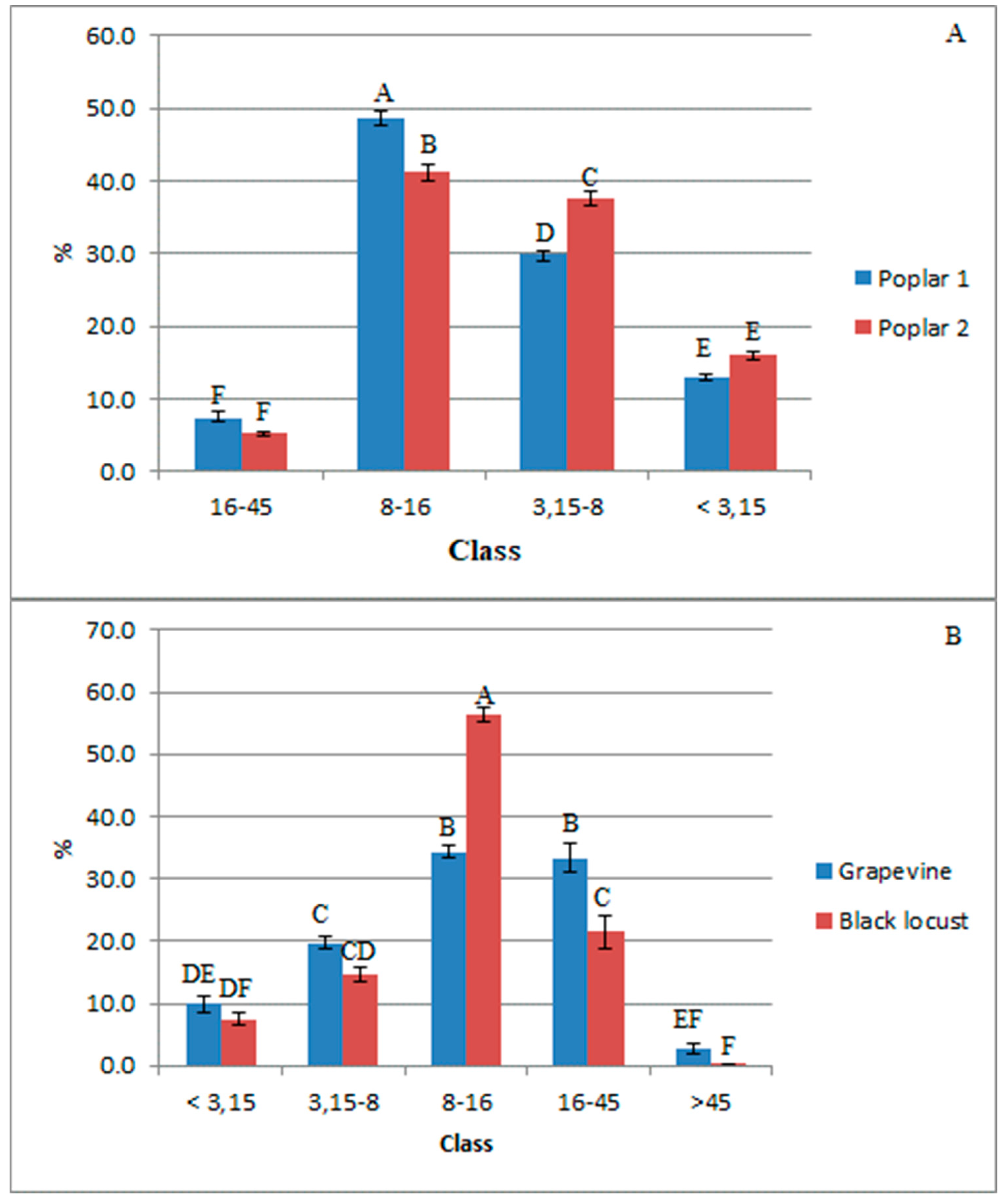
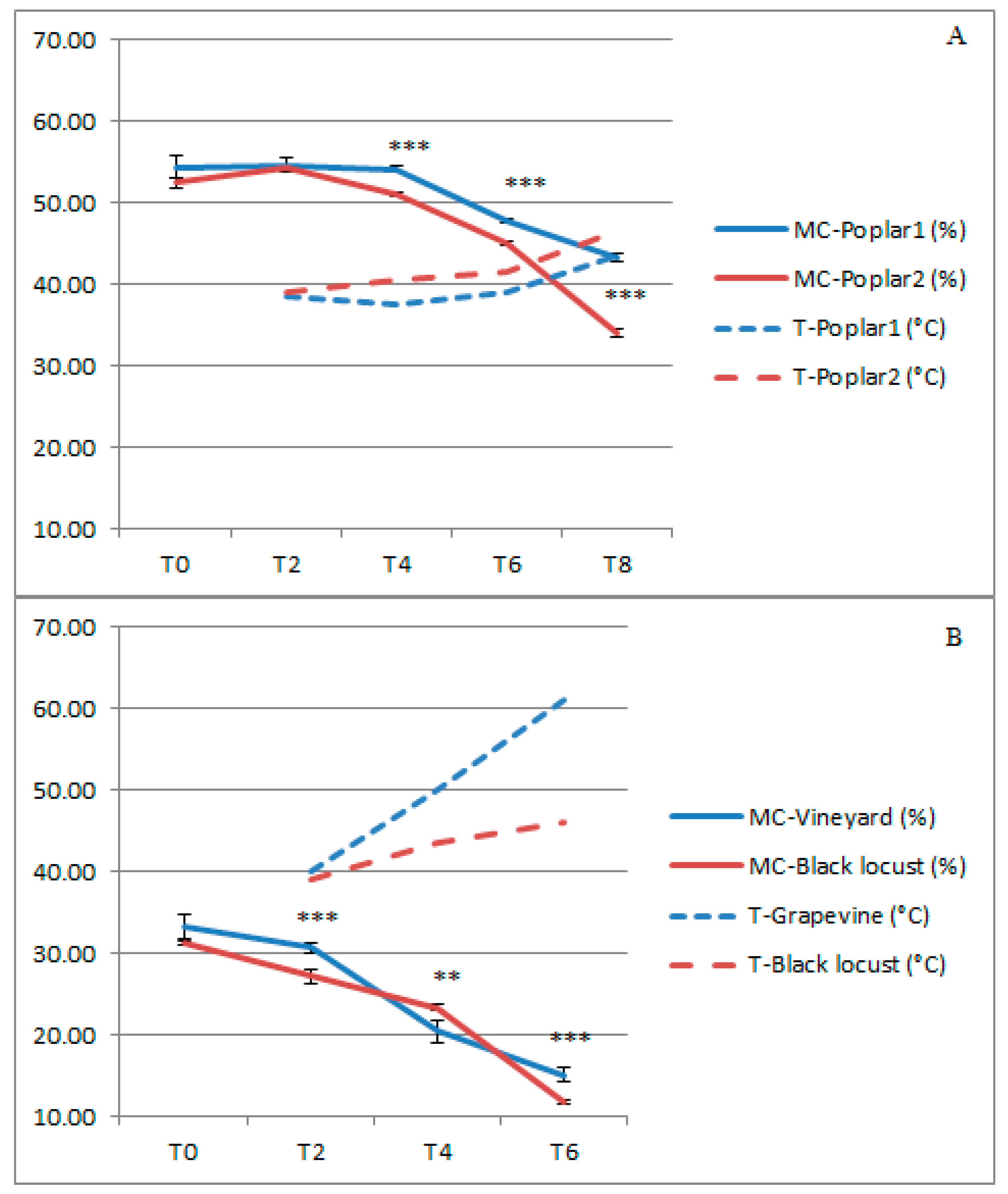
The characteristics of the biomass have shown to influence the technical parameters of the drying process. The moisture content of the biomass as well as the particle size distribution and the bulk density determined a difference in the intensity of airflow temperature, rate, and speed, and this in turn affected the energy demand of the rotary drier. In the present study, the drying process allowed a reduction of the moisture content of 35%, 53%, and 63% respectively for poplar, grapevine, and black locust, with a corresponding increase in the energy content of the biomass of the 52.1%, 33.1%, and 43.0%. On the other hand, at the same operating thermodynamic conditions, the data indicate a thermal efficiency for the grapevine of 12% compared to 37% of poplar and 27% of black locust.
Based on the results, in our opinion the rotary drier presented and assessed in the present study may be viewed as an interesting device for the small farms equipped with energy plants (biogas, gasifiers, and cogeneration). The main strengths of the prototype are the the simplicity of the design, the small size, and its easy handling and transportability. In agricultural contexts where the environmental awareness favours the adoption of energy approaches of self-consumption, the prototype may provide the opportunity to dry residual biomass at low cost through the recovery of waste heat from the energy plant. This choice may also entitle to access at incentive rates for the recovery of residual heat. Being a prototype, the drier is susceptible of further improvements increasing its efficience: these should concern the recirculation of the drying air, the thermal insulation of the dryer, and the increase in the temperature of the drying fluid.

Author Contributions

Conceptualization, A.D.G., A.A., E.S., L.P. and F.G.; Data curation, A.D.G. and E.S.; Formal analysis, E.S.; Funding acquisition, L.P. and F.G.; Investigation, A.D.G., A.A. and E.S.; Resources, F.P., V.P. and F.G.; Supervision, L.P. and F.G.; Writing—original draft, A.D.G. and E.S.; Writing—review & editing, S.B., E.G., F.P., M.T. and V.P.

Acknowledgments

This research was funded by the Ministry of Agriculture, Food, Forestry and Tourism (MiPAAFT) as part of grant D.M. N° 4056 of 24/07/2008 (FAESI project), D.M. N° 2420 of 20/02/2008 (BTT project) and D.D. N° 26329 of 01/04/2016 (AGROENER project).

Conflicts of Interest

The authors declare no conflict of interest.

References

  1. Colantoni, A.; Longo, L.; Gallucci, F.; Monarca, D. Pyro-Gasification of hazelnut using a downdraft gasifier for concurrent production of syngas and biochar. Contemp. Eng. Sci. 2016, 9, 1339–1348. [Google Scholar] [CrossRef]
  2. Nystrom, J.; Dahlquist, E. Methods for determination of moisture continent in wood chip for power plant—A review. Fuel 2003, 83, 773–779. [Google Scholar] [CrossRef]
  3. Maltoni, A.; Mariotti, B.; Tani, A. La Robinia in Toscana. La Gestione dei Popolamenti, L’impiego in Impianti Specializzati, il Controllo della Diffusione, Regione Toscana—DEISTAF: Dipartimento di Economia, Ingegneria, Scienze e Tecnologie Agrarie e Forestali Università di Firenze; Regione Toscana: Firenze, Italy, 2012. [Google Scholar]
  4. Wimmerstedt, R. Recent advances in biofuel drying. Chem. Eng. Prog. 1999, 38, 441–447. [Google Scholar] [CrossRef]
  5. Kaplan, O.; Celik, C. An experimental research on woodchip drying using a screw conveyor dryer. Fuel 2018, 215, 468–473. [Google Scholar] [CrossRef]
  6. Meza, J.; Gil, A.; Cortés, C.; González, A. Drying cost of wood biomass in a semi-industrial exsperimental rotary dryer. In Proceedings of the 16th European Conference & Exhibition on Biomass for Energy, Biomass Resources, Valencia, Spain, 2–6 June 2008. [Google Scholar]
  7. Svoboda, K.; Martinec, J.; Pohorely, M.; Baxter, D. Integration of biomass drying with combustion/gasification technologies and minimalization of organic compounds. Chem. Pap. 2009, 63, 15–25. [Google Scholar] [CrossRef]
  8. Spinelli, R.; Magagnotti, N. Il cippato forestale. In Foresta, Legno, Energia. Linee guida per lo sviluppo di un modello di utilizzo del cippato forestale a fini energetici; Press Service Firenze: Florence, Italy, 2007; pp. 69–103. [Google Scholar]
  9. Spinelli, R. Cippato: La raccolta della materia prima. Mondo Macchina 2008, 2, 56–59. [Google Scholar]
  10. Cuevas, M.; Martínez-Cartas, M.L.; Perez-Villarejo, L.; Hernandez, L.; García-Martín, J.F.; Sanchez, S. Drying kinetics and effective water diffusivities in olive stone and olive-tree pruning. Renew. Energy 2019, 132, 911–920. [Google Scholar] [CrossRef]
  11. McIlveen-Wright, D.R.; Williams, B.C.; McMullan, J.T. A re-appraisal of wood-fired combustion. Bioresour. Technol. 2001, 76, 183–190. [Google Scholar] [CrossRef]
  12. Schuster, G.; Löffler, G.; Weigl, K.; Hofbauer, H. Biomass steam gasification—An extensive parametric modelling study. Bioresour. Technol. 2001, 77, 71–79. [Google Scholar] [CrossRef]
  13. Belis, C.A.; Cancelinha, J.; Duanea, M.; Forcina, V.; Pedronia, V.; Passarella, R.; Tanet, G.; Douglas, K.; Piazzalunga, A.; Bolzacchini, E.; et al. Sources for PM air pollution in the Po Plain, Italy: I. Critical comparison of methods for estimating biomass burning contributions to benzo(a)pyrene. Atmos. Environ. 2011, 45, 7266–7275. [Google Scholar] [CrossRef]
  14. Petracchini, F.; Romagnoli, P.; Paciucci, L.; Vichi, F.; Imperiali, A.; Paolini, V.; Liotta, F.; Cecinato, A. Influence of transport from urban sources and local biomass combustion on the air quality of a mountain area. Environ. Sci. Pollut. Res. 2017, 24, 4741–4754. [Google Scholar] [CrossRef] [PubMed]
  15. Barontini, M.; Crognale, S.; Scarfone, A.; Gallo, P.; Gallucci, F.; Petruccioli, M.; Pesciaroli, L.; Pari, L. Airborn fungi in biofuel wood chip storage sites. Int. Biodeter. Biodegr. 2014, 90, 17–22. [Google Scholar] [CrossRef]
  16. Chapela, S.; Porteiro, J.; Gómez, M.A.; Patiño, D.; Míguez, J.L. Comprehensive CFD modeling of the ash deposition in a biomass packed bed burner. Fuel 2018, 234, 1099–1122. [Google Scholar] [CrossRef]
  17. Klavinia, K.; Cinis, A.; Zandeckis, A. A study of pressure drops in an experimental low temperature wood chip dryer. Agron. Res. 2014, 12, 511–518. [Google Scholar]
  18. Li, H.; Chen, Q.; Zhang, X.; Finney, K.N.; Sharifi, V.N.; Swithenbank, J. Evaluation of a biomass drying process using waste heat from process industries: A case study. Appl. Therm. Eng. 2012, 35, 71–80. [Google Scholar] [CrossRef]
  19. Fredrikson, R.W. Utilisation of Wood Waste as Fuel for Rotary and Flash Tube Wood Dryer Operation. In Proceedings of the Biomass Fuel Drying Conference Proceedings, Superior, WN, USA, 8 August 1984; Office of Special Programs, University of Minnesota: Minneapolis, MN, USA, 1984; pp. 1–16. [Google Scholar]
  20. Hulkkonen, S.; Parvio, E.; Raiko, M. An Advanced Fuel Drying Technology for Fluidized Bed Boilers. In Proceedings of the 13th International Conference on Fluidized Bed Combustion, Orlando, FL, USA, 7–10 May 1995; pp. 399–403. [Google Scholar]
  21. Lamidi, R.O.; Jiang, L.; Pathare, P.B.; Wang, Y.D.; Roskilly, A.P. Recent advances in sustainable drying of agricultural produce: A review. Appl. Energy 2019, 233–234, 367–385. [Google Scholar] [CrossRef]
  22. Ozollapins, M.; Kakitis, A.; Nulle, I. Stalk biomass drying rate evaluation. In Proceedings of the 12th International Scientific Conference Enginering for Rural Development, Jelgava, Latvia, 23–24 May 2013. [Google Scholar]
  23. Pang, S.; Mujumdar, A.S. Drying of woody biomass for bioenergy: Drying technologies and optimization for an integrated bioenergy plant. Dry. Technol. 2010, 28, 690–701. [Google Scholar] [CrossRef]
  24. Vigants, E.; Vigants, G.; Veidenbergs, I.; Lauka, D.; Klavina, K.; Blumberga, D. Analysis of Energy Consumption for Biomass Drying Process. In Proceedings of the 10th International Scientific and Practical Conference on Environment, Technology and Resources, Rezekne, Latvia, 18–20 June 2015; Volume II, pp. 317–322. [Google Scholar]
  25. AIEL. Sistemi di essiccazione. In Legna, Cippato e Pellet, Produzione, Requisiti Qualitativi, Compravendita; Associazione Italiana Energie Agroforestali (AIEL): Legnaro (PD), Italy, 2012; pp. 93–100. [Google Scholar]
  26. Kocsis, L.; Herdovics, M.; Deákvári, J.; Fenyvesi, L. Corn drying experiments by pilot dryer. Agron. Res. Biosyst. Eng. Special Iss. 2011, 1, 91–97. [Google Scholar]
  27. Grimm, D.; Elustondo, M.; Mäkelä, M.; Segerström, G.; Kalén, L.; Fraikin, A.; Léonard, S.; Larsson, H. Drying recycled fiber rejects in a bench-scale cyclone: Influence of device geometry and operational parameters on drying mechanisms. Fuel Process. Technol. 2017, 167, 631–640. [Google Scholar] [CrossRef]
  28. Gu, C.; Yuanb, Z.; Sunb, S.; Guanb, L.; Wub, K. Simulation investigation of drying characteristics of wet filamentous biomass particles in a rotary kiln. Fuel Process. Tchnol. 2018, 178, 344–352. [Google Scholar] [CrossRef]
  29. Zuccarello, B. La co-densificazione di sanse e residui di potature: Fattibilità tecnico-economica e sviluppo. In Proceedings of the Conference Progetto ECODENS—Ecostabilizzazione delle sanse mediante densificazione, Misura 124-PSR Sicilia, 2007–2013, Università degli Studi di Palermo, Palermo, Italy, 30 January 2014. [Google Scholar]
  30. Mujumdar, A.S. Handbook of Industrial Drying; CRC Press: Boca Raton, FL, USA, 2006. [Google Scholar]
  31. Kaplan, O.; Celik, C. Woodchip drying in a screw conveyor dryer. J. Renew. Sustain. Energy 2012, 4, 063110. [Google Scholar] [CrossRef]
  32. Xu, Q.; Pang, S. Mathematical modeling of rotary drying of woody biomass. Dry. Technol. 2008, 26, 1344–1350. [Google Scholar] [CrossRef]
  33. Krokida, M.; Marinos-Kouris, D.; Mujumdar, A.S. Rotary drying. In Handbook of Industrial Drying; Mujumdar, A.S., Ed.; CRC Press: Boca Raton, FL, USA, 2006; pp. 151–172. [Google Scholar]
  34. Lazdāns, V.; Lazdiņš, A.; Zimelis, A. Technology of biofuel production from slash in clear-cuts of spruce stands. For. Sci. 2009, 19, 109–121. [Google Scholar]
  35. Williams-Gardner, A. Industrial Drying; Leonard Hill Books Ltd.: London, UK, 1971. [Google Scholar]
  36. Brammer, J.; Bridgwater, A. Drying technologies for an integrated gasification bio-energy plant. Renew. Sustain. Energy Rev. 1999, 3, 243–289. [Google Scholar] [CrossRef]
  37. Maciejewska, A.; Veringa, H.; Sanders, J.; Peteves, C. Co-Firing of Biomass with Coal: Constraints and Role of Biomass Pre-Treatment; JRC’s Institute for Energy: Petten, The Nederlands, 2006. [Google Scholar]
  38. UNI EN 14774-2. Solid Biofuels, Determination of Moisture Content—Oven Dry Method. Part 2: Total Moisture—Simplified Method; Italian Authority for Standardization: Milano, Italy, 2010. [Google Scholar]
  39. UNI EN 15103. Solid Biofuels, Determination of Bulk Density; Italian Authority for Standardization: Milano, Italy, 2010. [Google Scholar]
  40. UNI EN 14961-1. Solid Biofuels, Determination of Particle Size Distribution. Part 1: Oscillating Screen Method Using Sieve Apertures of 1 mm and Above; Italian Authority for Standardization: Milano, Italy, 2011. [Google Scholar]
  41. ISO 3310-2. Test Sieves e Technical Requirements and Testing-Part 1: Test Sieves of Metal Wire Cloth; Italian Authority for Standardization: Milano, Italy, 2000. [Google Scholar]
  42. Hartmann, H. Handbuch Bioenergie-Kleinanlagen; Sonderpublikation des Bundesministeriums für Verbraucherschutz, Ernährung und Landwirtschaft (BMVEL) und der Fachagentur Nachwachsende Rohstoffe (FNR): Gülzow, Germany, 2007. [Google Scholar]
  43. Manzone, M.; Balsari, P.; Spinelli, R. Small-scale storage techniques for fuel chips from short rotation forestry. Fuel 2013, 109, 687–692. [Google Scholar] [CrossRef]
  44. Pari, L.; Assirelli, A.; Acampora, A.; Del Giudice, A.; Santangelo, E. A new prototype for increasing the particle size of chopped Arundo donax (L.). Biomass Bioenergy 2015, 74, 288–295. [Google Scholar] [CrossRef]
  45. Garcia-Galindo, D.; Gomez-Palmero, M.; Lopez, E.; Sebastián, F.; Jirjis, R.; Gebresenbet, G.; Germer, S.; Pari, L.; Suardi, A.; Lapeña, A.; et al. Agricultural pruning harvesting demostrationns in Germany, France, and Spain. Lessons learned reccommendations. In Proceedings of the 24th European Biomass Conference and Exhibition, Amsterdam, The Netherlands, 6–9 June 2016; pp. 1727–1733. [Google Scholar]
  46. Zhou, L.P.; Wang, B.X.; Peng, X.F.; Du, X.Z.; Yang, Y.P. On the Specific Heat Capacity of CuO Nanofluid. Adv. Mech. Eng. 2010, 1–4, 172085. [Google Scholar] [CrossRef]
  47. Tippayawong, N.; Tantakitti, S.; Thavornun, S. Energy efficiency improvements in longan drying practice. Energy 2008, 33, 1137–1143. [Google Scholar] [CrossRef]
  48. Langsrud, Ø.; JØrgensen, K.; Ofstad, R.; Næs, T. Analyzing designed experiments with multiple responses. J. Appl. Stat. 2007, 34, 1275–1296. [Google Scholar] [CrossRef]
  49. Jakob, K. Black locust (Robinia pseudoacacia L.). In Energy Plant Species, Their Use And impact on Environment and Development; James & James (Science Publishers) Ltd.: London, UK, 1998; pp. 98–103. [Google Scholar]
  50. Kraszkiewicz, A. Chemical composition and selected energy proprieties of Black locust bark (Robinia pseudoacacia L.). Agric. Eng. 2016, 20, 117–124. [Google Scholar]
  51. Hellrigl, B. Elementi di Xiloenergetica. Definizioni, Formule e Tabelle; AIEL-Italian Agriforestry Energy Association: Padova, Italy, 2006. [Google Scholar]
  52. Civitarese, V.; Del Giudice, A.; Suardi, A.; Santangelo, E.; Pari, L. Study on the effect of a new rotor designed for chipping short rotation woody crops. Croat. J. For. Eng. 2015, 36, 101–108. [Google Scholar]
  53. Anderson, J.-O.; Westerlund, L. Improved energy efficiency in sawmill drying system. Appl. Energy 2014, 113, 891–901. [Google Scholar] [CrossRef]
  54. Johansson, L.; Westerlund, L. An open absorption system installed at a sawmill description of pilot plant used for timber and bio-fuel drying. Energy 2000, 25, 1067–1079. [Google Scholar] [CrossRef]
  55. Chua, K.J.; Mujumdar, A.S.; Hawlader, M.N.A.; Chou, S.K.; Ho, J.C. Batch drying of banana pieces—Effect of stepwise change in drying air temperature on drying kinetics and product color. Food Res. Int. 2001, 34, 721–731. [Google Scholar] [CrossRef]
  56. Ogura, H.; Yamamoto, T.; Otsubo, Y.; Ishida, H.; Kage, H.; Mujumdar, A.S. A control strategy for chemical heat pump dryer. Dry. Technol. 2005, 23, 1189–1203. [Google Scholar] [CrossRef]
  57. De Fusco, L.; Jeanmart, H.; Blondeau, J. A modelling approach for the assessment of an air-dryer economic feasibility for small-scale biomass steam boilers. Fuel Process. Technol. 2015, 134, 251–258. [Google Scholar] [CrossRef] [Green Version]
Figure 1. Rotary dryer prototype (a); dust recovery system (b).
Energies 12 01590 g001
Figure 2. Intertwined flights inside of cylinder (a,b); schematic representation of the system (c).
Energies 12 01590 g002
Figure 3. Mobile rotary dryer connected to a boiler of the power of 80 kW.
Energies 12 01590 g003
Figure 4. Schematic representation of the system and the points (checkpoint and probe) where the temperature and the airflow were recorded during the test.
Energies 12 01590 g004
Figure 5. Particle size distribution (mean ± SE) of the wood chips: (A) Poplar 1 and Poplar 2; (B) grapevine and black locust. Within each size class, different letters indicate a significant difference at the level of P ≤ 0.01 after Tuckey’s HSD test. Before the ANOVA analysis the data were transformed as square root of the arcsine.
Energies 12 01590 g005
Figure 6. Mean (±SD) of the moisture content (MC, solid line) and the temperature (T, dotted line) inside the cylinder at each time-point of the drying cycle: (A) Poplar 1 and Poplar 2; (B) grapevine and black locust. For the moisture content, significant differences between treatment within each time were determined by Student’s t-test. Where reported, ** P < 0.01 and *** P < 0.001 probability level.
Energies 12 01590 g006
Figure 7. Principal component analysis of the thermodynamic variables monitored during the drying of the wood chips of poplar, grapevine and black locust.
Energies 12 01590 g007
Table 1. Main characteristics of the wood chips (mean ± SD) before drying.
BiomassAmount (kg)Moisture Content (%)Calorific Value (MJ·kg−1)Bulk Density (kg/m3)
Poplar 1250.054.4 ± 1.47.1 ± 0.3280.6 ± 8.4
Poplar 2250.052.5 ± 0.67.5 ± 0.1285.2 ± 3.2
Grapevine143.733.3 ± 1.511.5 ± 0.3199.3 ± 8.2
Black locust207.031.2 ± 0.312.0 ± 0.1358.5 ± 10.5
Table 2. Mean particle size and resistance to air flow (mean ± SD) before drying. For each column, different letters indicate a significant difference at the level of P ≤ 0.01 after Tuckey’s HSD test.
BiomassMean Particle Size (mm)A
Poplar 164.0 ± 8.7 B511.1 ± 68.9 B
Poplar 239.2 ± 6.0 C786.0 ± 100.2 A
Grapevine145.0 ± 45.4 A263.9 ± 78.8 C
Black locust68.3 ± 7.8 B480.4 ± 46.6 B
Table 3. Main results of the Anova on the characteristics of the airflow.
Source of VariationTemperatureRateSpeed
FpFpFp
Species1.720.18439.860.00048.660.000
ChP147.300.000145.600.0008.810.001
Species X ChP4.330.0030.680.6664.340.003
Table 4. Features of the airflow monitored during the drying test (mean ± SD). For each variable, different letters indicate a significant difference at the level of P ≤ 0.01 after Tuckey’s HSD test.
VariableChPPoplar 1Poplar 2GrapevineBlack Locust
Temperature (°C)173.75 ± 4.22 A76.85 ± 1.14 A60.40 ± 9.69 AC64.30 ± 11.97 AB
271.23 ± 4.23 A72.15 ± 2.85 A60.27 ± 10.00 AC67.47 ± 48.79 AB
328.58 ± 1.15 D31.10 ± 0.84 D41.97 ± 10.31 BD34.87 ± 2.99 CD
Airflow rate (m3·h−1)11035.99 ± 47.641004.40 ± 70.59809.52 ± 155.50811.80 ± 49.98
2948.24 ± 16.13978.03 ± 47.06734.88 ± 139.58775.80 ± 26.82
3659.79 ± 49.67625.41 ± 36.56332.88 ± 54.05396.31 ± 6.64
Speed (m·s−1)15.79 ± 0.33 A5.70 ± 0.37 A4.63 ± 0.91 AC4.59 ± 0.28 AC
25.28 ± 0.05 AB5.49 ± 0.26 A4.08 ± 0.73 AC4.52 ± 0.11 AC
35.76 ± 0.41 A5.53 ± 0.36 A2.95 ± 0.46 C3.48 ± 0.02 C
Table 5. Energy parameters (average data for each drying cycle).
ParameterPoplar 2GrapevineBlack Locust
Biomass fuel used (kg) 806052
Dried biomass (kg)208.398.8142.2
Quantity of H2O evaporated (kg) 41.744.964.8
Heating value * (MJ·Kg−1)
- wet basis7.5011.5311.96
- dry basis11.3415.3517.10
* Energy content related to the moisture content of the biomass after the drying process.
Table 6. Thermal energy balance (average data for each drying cycle).
ParameterPoplar 2GrapevineBlack Locust
ItemThermal Energy Utilization
Energy input (MJ·kgdry solid 1)4.356.884.14
Heat for drying Q (MJ·kgdry solid1)1.610.861.12
Losses (MJ·kgdry solid−1)2.746.023.02
Drying efficiency η (%)371227

