Modeling and Evaluation of Stator and Rotor Faults for Induction Motors


1
School of Electrical Engineering, Beijing Jiaotong University, Beijing 100044, China
2
China Academy of Railway Sciences Co. Ltd., Beijing 100081, China
3
Department of Energy Technology, Aalborg University, 9220 Aalborg, Denmark
4
Beijing Qiansiyu Electric Co. Ltd., Beijing 100082, China
5
Beijing Engineering Research Center for Electrical Rail Transit, Beijing 100044, China
*
Author to whom correspondence should be addressed.
Energies 2020, 13(1), 133; https://0-doi-org.brum.beds.ac.uk/10.3390/en13010133
Submission received: 5 November 2019
/
Revised: 20 December 2019
/
Accepted: 20 December 2019
/
Published: 26 December 2019
(This article belongs to the Special Issue Design and Analysis of Electric Machines)
Abstract
:The modeling of stator and rotor faults is the basis of the development of online monitoring techniques. To obtain reliable stator and rotor fault models, this paper focuses on dynamic modeling of the stator and rotor faults in real-time, which adopts a multiple-coupled-circuit method by using a winding function approach for inductance calculation. Firstly, the model of the induction machine with a healthy cage is introduced, where a rotor mesh that consists of a few rotor loops and an end ring loop is considered. Then, the stator inter-turn fault model is presented by adding an extra branch with short circuit resistance on the fault part of a stator phase winding. The broken rotor bar fault is then detailed by merging and removing the broken-bar-related loops. Finally, the discrete models under healthy and faulty conditions are developed by using the Tustin transformation for digital implementation. Moreover, the stator and rotor mutual inductances are derived as a function of the rotor position according to the turn and winding functions distribution. Simulations and experiments are performed on a 2.2-kW/380-V/50-Hz three-phase and four-pole induction motor to show the performance of the stator and rotor faults, where the saturation effect is considered in simulations by exploiting the measurements of a no load test. The simulation results are in close agreement with the experimental results. Furthermore, magnitudes of the characteristic frequencies of 2f1 in torque and (1 ± 2s)f1 in current are analyzed to evaluate the stator and rotor fault severity. Both indicate that the stator fault severity is related to the short circuit resistance. Further, the number of shorted turns and the number of continuous broken bars determines the rotor fault severity.
1. Introduction
It is reported that 37% of stator faults and 10% of rotor faults occur in induction motors in industry applications [1]. In the early stage, most of the stator faults and rotor faults are caused by turn-to-turn insulation failures [2] and broken bar faults [3], respectively. There are many factors that result in stator and rotor faults, including thermal, mechanical, and environmental stresses. For instance, it was indicated in [4] that the insulation degradation of stator windings is the main cause for stator inter-turn faults, where the thermal stress is the most recognized factor for the ultimate insulation failure [5]. Other reasons such as partial discharges (PD) [5] also lead to the insulation decrease, especially in applications with voltage source inverters. Furthermore, in [5] and [6], it has been illustrated that the rotor faults are developed from manufacturing defects, thermal and mechanical stresses. The thermal expansion can lead to rotor internal misalignment or shaft bending, which will cause rotor unbalancing [7]. To address the fault issues, stator and rotor fault diagnosis methods based on signal processing technologies, modeling or parameters, and artificial intelligence have been developed in the literature. Nevertheless, to explore the degradation of the induction motor performance and to release the online monitoring, reliable models of stator and rotor faults are of importance.
Accordingly, a stator fault model in steady state was introduced in [8], and however, it is not suitable for the analysis of the dynamic performance. In [9], the stator fault in the natural a-b-c reference frame was established by considering the stator parameters as a function of the three short-circuited windings. In [10,11,12,13], an extra branch with short-circuit-resistance was added on the fault part with shorted turns of stator windings, where the stator fault model at the d-q-0 reference frame has been further derived to separate the healthy and faulty components in the equations. In addition, [14] describes the stator fault model in the d-q-0 stationary reference frame, where the parameter changes due to faults are calculated in detail. However, the space harmonics due to the non-sinusoidal distribution of stator windings are not considered.
Most rotor fault models are based on the winding function approach, where the rotor cage is considered as a mesh that contains rotor loops (the number of rotor loops is equal to the number of rotor bars) and an end ring loop [15,16,17]. In [6], the steady state rotor fault was analyzed by merging the double rotor loops of the two adjacent loops, whose currents flow through the broken bar. Here, in this case, the stator current consists of the components of the main frequency and fault sidebands. Similarly, [18] analyzed the transient performance of cage induction motors under stator and rotor faults, where the rotor fault is simulated by modifying the column and row elements of the rotor loop related to the broken bar. Furthermore, [17] proposed a symmetrical components theory to simplify the analysis of the unbalance of the three-phase power system for rotor broken bar fault detection. In addition, the modeling of rotor fault was presented in [19,20,21] by considering a resistance ∆Rr added on the d- or q-axis rotor resistance of the healthy rotor to break the rotor symmetry at the two-phase rotor rotation axis.
Reliable stator and rotor fault models are very important to achieve online faults detection. With this consideration, this paper focuses on the dynamic modeling of stator and rotor faults. The influence of space harmonics and magnetizing saturation is investigated, which is suitable for any excited voltage and any arrangement of stator windings. The rest of the paper is organized as follows. Section 2 introduces models of healthy systems, stator and rotor faults based on the winding function method. Section 3 proposes an improved method for stator-rotor mutual inductance calculation in real-time based on the winding function and turn function distributions with respect to the rotor position. Section 4 demonstrates the simulation results of the stator and rotor faults, where the severity of stator and rotor faults under different cases are further analyzed (i.e., the torque and current spectrum analysis). Section 5 shows the experimental results on a 2.2-kW/380-V/50-Hz induction motor under healthy, stator and rotor faulty conditions, where the saturation is considered as a coefficient related to the magnetizing flux. The conclusion of this paper is presented in Section 6.
2. Stator and Rotor Fault Models
As aforementioned, the fault models are crucial for online monitoring of induction motors. For simplicity, the following assumptions are considered: (a). It is assumed that the motor is supplied by a balanced three-phase voltage source; (b) The air gap is uniformed, and the motor has no eccentricity; (c) Rotor bars are insulated to each other, and there is no inter-bar current. With those assumptions, voltage and flux expressions of a three-phase induction motor with nb rotor bars can be derived, which will be presented in the following.
2.1. Modeling of Healthy Induction Motors
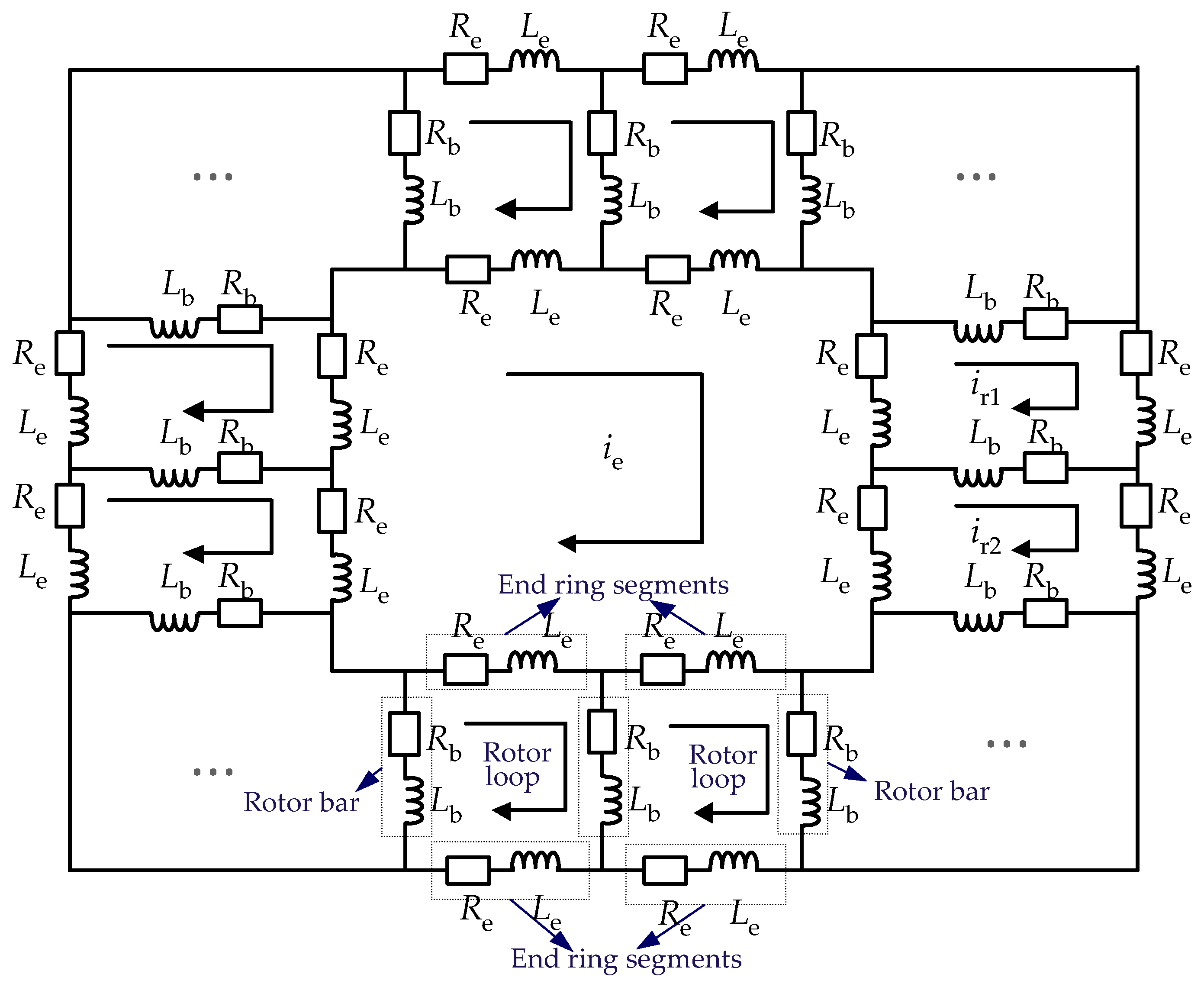
The equivalent circuit of the rotor cage is described as a mesh, which is shown in Figure 1. Here, Rb and Lb are the rotor bar resistance and leakage inductance, respectively; Re and Le are the resistance and leakage inductance of the end ring segment, respectively; ir1 and ir2 represent the currents of the first and second rotor loop, respectively; ie is the end ring current. It can be observed in Figure 1 that the arbitrary rotor loop comprises of two adjacent rotor bars, together with the end ring segments.
According to the above mesh model, the first rotor loop can be described as
where irnb represents the current of the nb-th rotor loop and “p” is the derivation operation. Then, it can be simplified as
Next, the couplings to other rotor loops and to stator phases are considered, which leads to the following voltage equation:
in which λr1 is the flux of the first rotor loop, Lr1sx is the mutual inductance between the first rotor loop and phase x in the stator (x = A, B, C), Lr1rj is the mutual inductance of the first to jth rotor loop (j = 1, 2,…, nb), Lr1e is the mutual inductance between the first rotor loop and the end ring, and Lr1e = 0.
The voltage and flux expressions of the rest rotor loops can be obtained in the same way. Moreover, for the end ring, its current does not couple with stator phases, and thus,
The aforementioned rotor mesh shows that there are nb rotor loop currents and an end ring loop current, along with three-phase stator currents. There are (nb + 4) un-known currents in total for a healthy three-phase induction motor with nb rotor bars. Therefore, the healthy motor model can be described as
(1) Voltage equations
where,
with Rs being the stator resistance of the symmetry stator.
(2) Flux equations
where,
in which Lsisj is the mutual inductance between phase i and phase j (i = a, b, c; j = a, b, c); the way of other definitions is the same as that of the first loop. It should be noted that the stator and rotor mutual inductances depend on the rotor position during motor operation.
(3) Torque and speed equations
where Te and TL are the electromagnetic torque and load torque, respectively, ωm and θm are the mechanical angular speed and angle, respectively, and J is the inertia of the motor.
Substituting Equation (8) into (7), the healthy motor can be described by the vector given as
2.2. Modeling of Stator Faults
If a stator fault is presented in the motor, an extra branch with short circuit resistance Rf will be added on the short part in the stator winding, as shown in Figure 2. The current if flows through the short circuit resistance Rf, and thus, the current of the fault part in the stator winding is (isa-if) according to the Kirchhoff’s current law.
Figure 2 further shows that the stator fault is located at phase A. The parameters related to faulted turns are considered to be proportional to the number of shorted turns nsf. For example, the stator resistance of the shorted part is ksfRs (ksf = nsf/zs, and zs is the total number of stator slots), whereas the resistance of the healthy part is (1 − ksf)Rs. Hence, the voltage equations of the stator phase A and shorted circuit are derived as
Notably, other equations related to the shorted phase should be updated accordingly. As a consequence, the vector of the stator fault model can be simplified as
where , , , , , and .
2.3. Modeling of Rotor Faults
When a rotor bar broken fault is presented in the induction motor, the broken bar is removed from the loop, as shown Figure 3, where the first rotor bar is broken. It can be seen from Figure 3 that the two adjacent rotor loops surrounding the broken bar are combined into one rotor loop, and the combined loop can be described as:
which can be simplified as
where ir1’ is the current of the combined rotor loop when the rotor bar broken is presented. Thus, considering the inductances, the voltage and flux equations of the combined rotor loop are described as
in which Lr1sa’, Lr1sb’, Lr1sc’ are the mutual inductance between the combined rotor loop and stator phase A, B, and C respectively, and it has relationships of Lr1sa’ = Lr1sa + Lr2sa, Lr1sb’ = Lr1sb + Lr2sb, Lr1sc’ = Lr1sc + Lr2sc; Lr1r1’, Lr1r3’, …, Lr1rnb’, Lr1e’ are the self and mutual inductances of the first rotor loop, similarly, Lr1rj’ = Lr1rj + Lr2rj (j = 1, 2, …). It can be observed from Equations (17) and (18) that the voltage and flux of the combined first loop are equivalent to the case by adding the parameters of the second column and line of the parameter matrices under healthy condition to the first column and line with further simplification.
Therefore, the vector expression of the rotor broken bar model is given as
where
2.4. Discretization
To realize the above healthy and faulty models in MATLAB/SIMULINK, the digital implementation of these models should be considered. The above derived models involve in a large amount of matrix calculations, and thus, it is necessary to find a suitable discrete method to reduce further computation cost and improve calculation accuracy. Currently, the well-known discrete methods include the first order forward/backward Euler methods, Tustin transformation, and Runge–Kutta method. Among those, the Tustin transformation not only has higher computation accuracy, but also has a lower calculation cost. It can be expressed as
where Ts is the sampling period. Then, the model of the healthy, stator and rotor fault motors can be written as the following uniformed expression
with u(t) and i(t) being the voltage and current vector matrix; Φ1 and Φ2 representing the state matrix that depend on the models. Therefore, the discrete model is given as
in which ik and ik−1 are the current vectors at the kth and (k − 1)th steps, respectively; uk and uk−1 are the voltage vectors at the kth and (k − 1)th sampling instant.
3. Inductance Calculations
The inductances in the derived motor models are crucial for computation. The rotor bar leakage inductance Lb and end ring leakage inductance Le can be easily calculated through the geometric parameters of the machine. The relevant inductances can be calculated by using the winding function method. The induction motor studied in this paper is a three-phase four-pole machine, which has 36 stator slots and 28 rotor bars. Each stator phase has six coils, and each coil has 42 turns, and thus, the total number of turns of one stator phase is 252 turns. According to the winding function, the inductances are calculated, which will be detailed in the following.
3.1. Stator Inductances Calculation
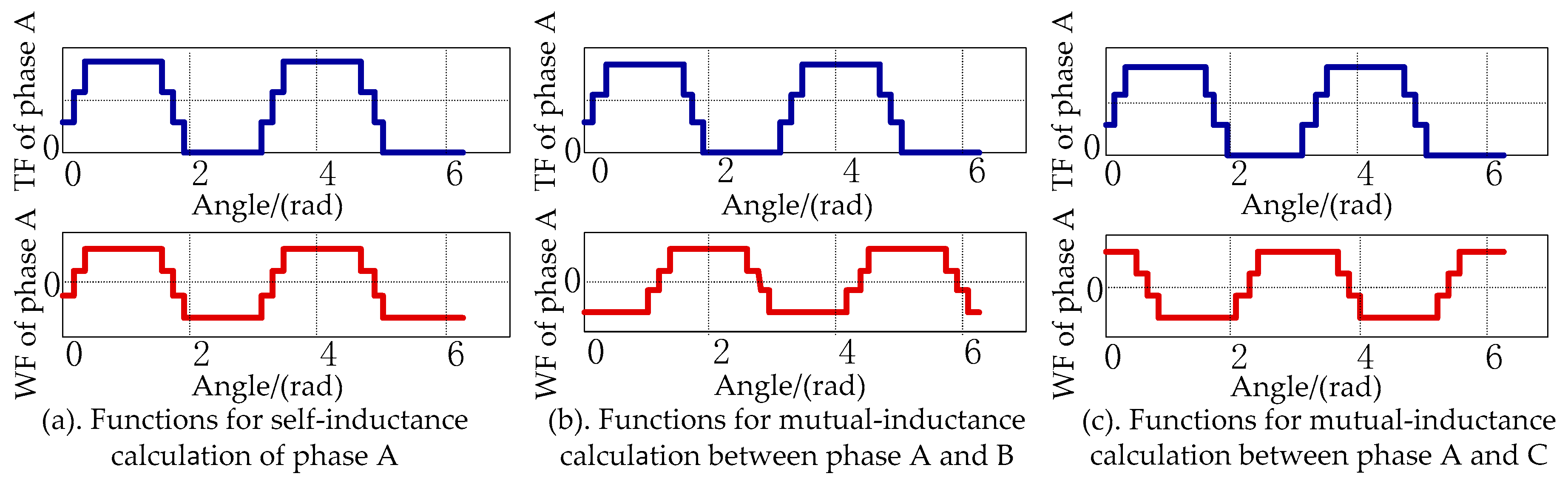
The turn function and winding function distribution for self and mutual inductances calculation of the stator phase A is shown in Figure 4. Furthermore, the inductances in the matrix Lsabc can be calculated according to
which describes the inductance calculation expression of coil A to coil B. Here, in (23), μ0 is the air gap permeability; r is the inside radius of the stator core; l is the length of the stator core; nA is the turn function of coil A; FB is the winding function of coil B; g is the length of the air gap, which is constant if the eccentricity is ignored.
3.2. Rotor Inductance Calculations
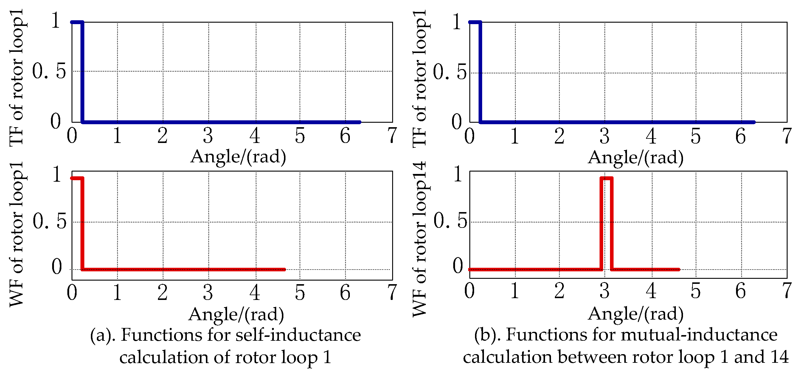
In order to calculate the rotor inductances, the rotor loop is taken as a coil and it has only one turn. Figure 5 presents the turn functions (TF) and winding functions (WF) for the inductance calculation of the rotor loop 1. Figure 5a shows the TF and WF of the rotor loop 1, and thus, the self-inductance can be calculated according to the TF and WF. It can be observed from Figure 5b that the winding function of the rotor loop 14 is the result of the shift of the WF of the rotor loop 1 to the right by 14 2π/28. Similarly, the WF of the kth rotor loop can be obtained by shifting the angle of k 2π/28. Hence, all the mutual inductances of rotor loops can be obtained, as shown in Figure 6, which gives the calculated inductances of the rotor loop 1. It can be observed in Figure 6 that the mutual inductances are negative, and their values are identical.
3.3. Transient Mutual Inductance bewteen Stator Phases and Rotor Loops Calculation
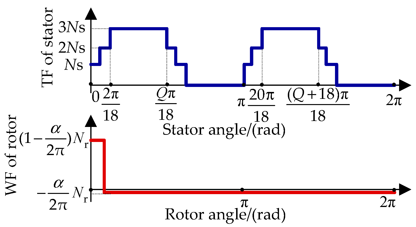
The mutual inductance calculation of stator phases to rotor loops is important, but it is difficult because the rotor position changes when the motor is running. In order to realize the real-time calculation of mutual inductances, the TF and WF with 0 ≤ θm < 2π/18-α are shown in Figure 7. Here, the mutual inductance can be calculated as
where α is the angle between two adjacent rotor slots; Ns and Nr is the number of turns of a stator and rotor coil, respectively, with Nr = 1; Q is the pitch of stator coil. It can be seen in Figure 7 that the position of the rotor loop 1 related to the stator phase A determines the overlapping area for the inductance calculation according to the TFs and WFs distribution. Consequently, Table 1 gives the derived mutual inductance expressions and its derivation, as a function of the rotor position. The mutual inductances between stator phases to other rotor loops are identical, as given in Table 1, but they are shifted by a certain number of angles that depend on their relative positions. For example, the mutual inductances between the stator phase B and C to the rotor loop 1 are shifted to the right by 2π/3 and 4π/3, respectively.
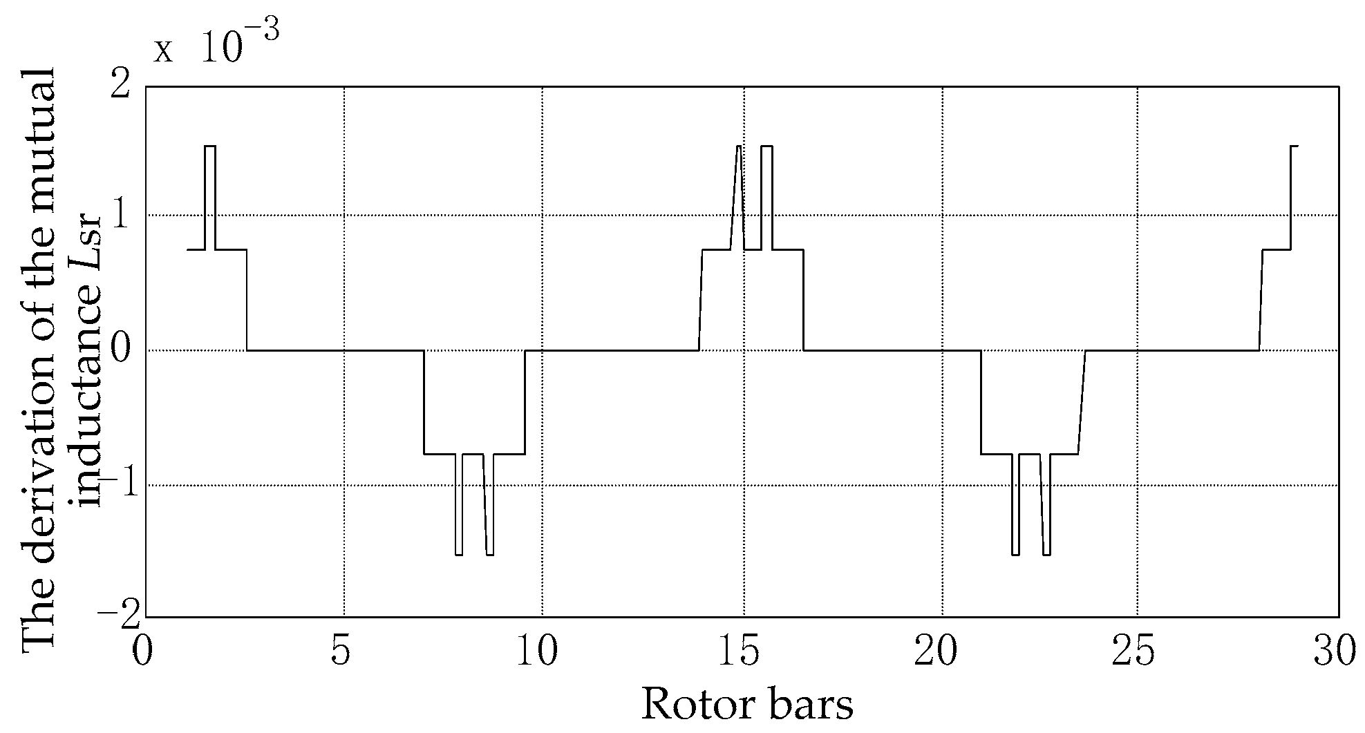
Therefore, the mutual inductances of the rotor loop 1 to the stator phase A will be progressively in phase around the rotor periphery. Then, the mutual inductances can be obtained by using the above derivations, which can be plotted as shown in Figure 8. Furthermore, the derivation to the rotor position is shown in Figure 9.
4. Simulation Results
To analyze the impact of stator and rotor faults, the proposed fault models are simulated on a 2.2-kW/380-V/50-Hz induction motor, whose parameters are given in Table 2. The motor is supplied by a balanced sinusoidal voltage (380-V/50-Hz). The simulation results for the stator faults and rotor faults are presented in the following section.
4.1. Stator Faults
Figure 10 shows the currents of the stator phases under healthy and faulty conditions. It can be observed from Figure 10a that the currents are balanced for a healthy motor. Observations of the currents in Figure 10b indicate that the magnitudes of currents are not equal. More specifically, the current magnitude of the phase B is smaller than that of the phases A and C. Furthermore, the currents in Figure 10c are notably unbalanced compared to the currents in Figure 10b, where the current of the phase B is significantly lower.
It has been reported that stator faults result in negative currents in the stator [22], which will produce 2f1 (f1 is the fundamental frequency) components in the power [23] and electromagnetic torque [24]. According to the measurements, the torque is calculated and further analyzed through the fast Fourier transform (FFT) technique. Figure 11 illustrates the torque spectrum of the induction motor under healthy and stator fault conditions. It can be observed in Figure 11 that the torque magnitude at 100 Hz (2f1) of the healthy motor is very small compared to the short-circuit fault motor. In addition, the torque magnitude at 100 Hz with Rf = 0.1 Ω is higher than that with Rf = 1 Ω, i.e., it is less serious for a larger Rf. Therefore, it can be concluded from the simulations that the stator fault severity is related to the short circuit resistance Rf. That is, the smaller Rf is, the more serious the impact is.
Furthermore, if Rf is fixed at 0.1 Ω, changing the number of shorted turns, the currents under different shorted turns can be obtained, as shown in Figure 12. Comparing the currents in Figure 12b and Figure 12c, it can be observed that the currents in Figure 12c are unbalanced, where the current of the phases A and C in Figure 12c is increased. However, in this case, the current of the phase B is decreased, when compared with Figure 12b.
Figure 13 further shows the torque spectrum of the stator fault, where the torque magnitudes at 100 Hz (2f1) of 1-turn (1T) and 5-turn (5T) shorted motors are increased compared to the healthy stator. It also can be seen in Figure 13 that the 5-turn shorted stator has a higher torque magnitude than the 1-turn shorted stator. Therefore, the stator fault severity is related to not only the short circuit resistance, but also the number of the shorted turns.
4.2. Rotor Faults
One broken rotor bar and three broken rotor bars faults are investigated in the simulation according to the above derived rotor faults model. The stator currents are shown in Figure 14. It can be observed in Figure 14 that the magnitudes of the currents of one broken rotor bar motor slightly vary in the simulation period when compared with the healthy condition. For the three broken rotor bars case, the magnitude pulsation is more obvious, as shown in Figure 14.
It is proven that the rotor asymmetry can cause (1 ± 2s)f1 sidebands in the stator current [25,26], where s is the slip. The current spectrums of the healthy and broken rotor bar motors are analyzed, as presented in Figure 15. It is indicated in Figure 15 that the (1 ± 2s)f1 component in the healthy current is negligible, while the (1 ± 2s)f1 component in the motor current of three broken rotor bars is larger than that of the one broken rotor bar. Therefore, it can be seen that the (1 ± 2s)f1 component is produced in the rotor fault, where the number of continuous broken bars determines the severity of rotor faults.
5. Experimental Results
Experimental tests are performed on a 2.2-kW/380-V/50-Hz induction motor in this paper under healthy, stator and rotor faults conditions. The stator inter-turn fault motor is provided through shorting the addition taps connected to the stator coils, and the rotor broken bar fault is created by drilling holes in contiguous rotor bars. When the induction motor with the stator or rotor asymmetry is excited by the balanced sinusoidal voltage source, the motor currents and speed are measured for further analysis and assessment.
5.1. Healthy Motors
The experimental results of the stator currents are shown in Figure 16, when the balanced sinusoidal voltage is applied in the healthy induction motor. The performance is also compared with the simulation results. It can be observed from Figure 16 that the current magnitude in the experimental tests is larger than that in simulations. The difference between simulation and experimental results is due to the existence of the magnetizing saturation.
More specifically, in the motor steady-state equivalent circuit, the saturation is explained as the deviation of magnetizing inductance. Thus, the saturation can be included in terms of adjusting the value of magnetizing inductance in the motor-equivalent-circuit-based model. In general, the magnetizing inductance can be described as a function of magnetizing current, in which their relationship can be fitted as a function through the measurements of no-load tests. It should be noted that the magnetizing current cannot be calculated directly.
Thus, this paper proposes to impose the magnetizing flux λm for the Lm calculation, and subsequently, to realize the analysis of the saturation effect in the proposed multiple-coupled-circuit models in simulations. The first step is to calculate λm in the simulation; then, the magnetizing current Im is obtained through the function of Im and λm based on offline no-load tests; finally, Lm is calculated according to Lm = λm/Im, and thus, ksat is induced to define the coefficient of the saturation effect as
where Lm is the adjusted magnetizing inductance according to the three calculation steps; Lm0 is the magnetizing inductance without saturation, which can be obtained using the winding function approach. Furthermore, the calculated ksat is used to adjust the inductances in matrices of Lsabc, Lsr, and Lr.
The whole procedure with the consideration of saturation effect in simulations is summarized as Figure 17. When the saturation effect is considered in the models, the currents are obtained, as shown in Figure 18. It can be observed that the currents from simulations and experimental tests are well in agreement with each other. That is, the method to impose the magnetizing flux shown in Equation (24) is validated.
5.2. Stator Faults
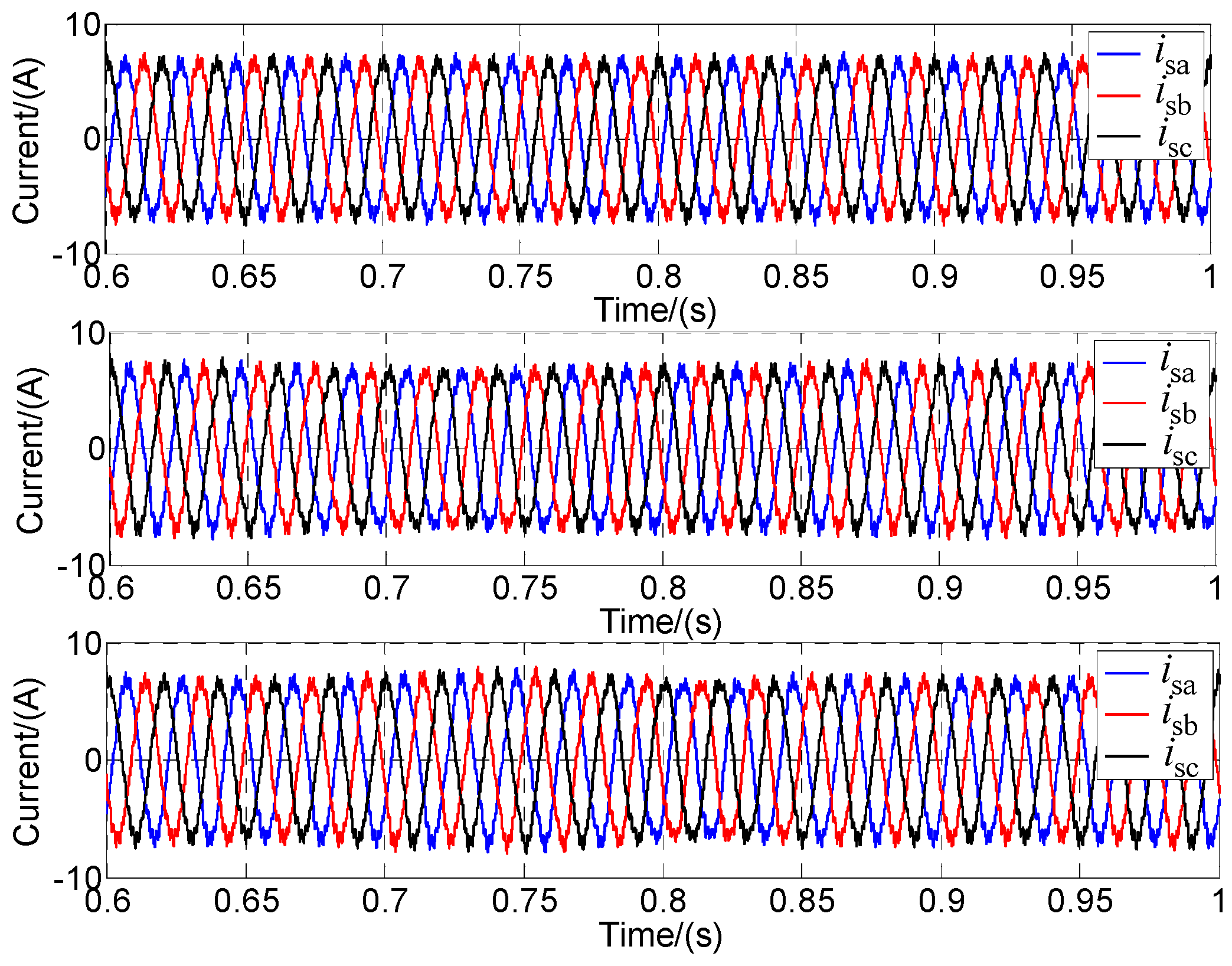
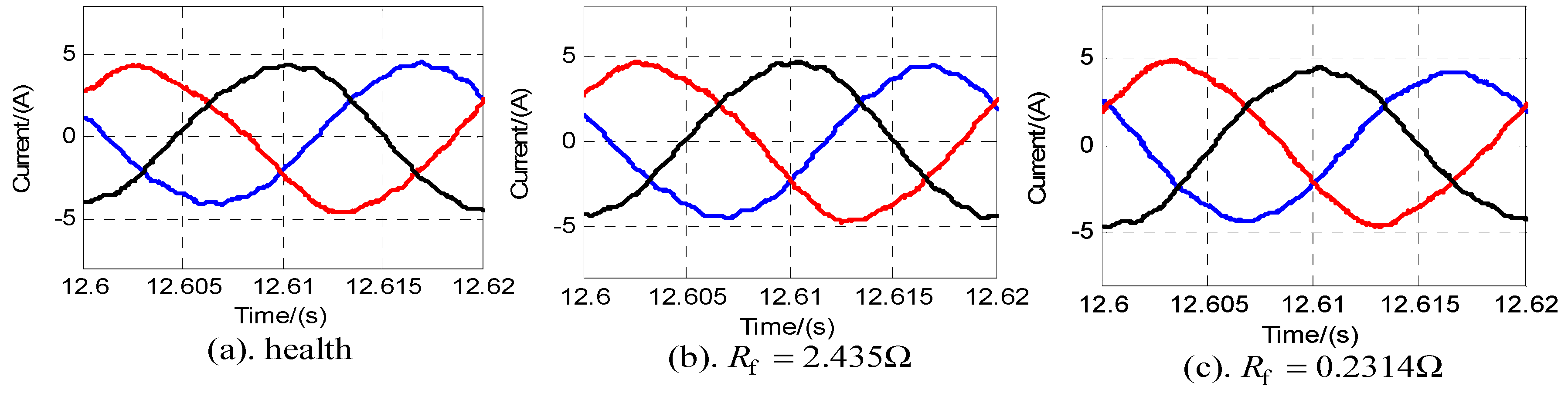
The stator currents of the five-turn shorted fault under different short circuit resistances are measured and shown in Figure 19. Figure 19a shows the appearance of the unbalance of three phase currents even for the healthy motor, which is caused by the unavoidable unbalanced three phase voltages in the experiments. When analyzing Figure 19b, it is known that there is no apparent distinction with respect to Figure 19a. In contrast, it is observed from Figure 19c that the unbalance of the currents is significant, where Rf is ten times smaller compared to Figure 19b.
In order to analyze the influence of the stator fault, the torque spectrums for the fault cases in Figure 19 are presented in Figure 20. It can be observed that the torque magnitude at 100 Hz (2f1) for the healthy motor is comparatively high because of the unbalanced voltage. Moreover, the torque magnitudes at 100 Hz under the stator faults are larger than that under the healthy condition. In addition, it also can be seen in Figure 19 that the lower the short circuit resistance is, the higher the torque magnitude at 100 Hz in the torque spectrum will be.
The measured currents are then compared considering the different number of shorted turns with Rf = 0.1 Ω, and the torque spectrums are further analyzed, as shown in Figure 21 and Figure 22, respectively. It can be observed from Figure 21 and Figure 22 that the degree of unbalance or the torque magnitude of 100 Hz increases with the increasing of the number of shorted turns.
When comparing with the simulation results in Figure 10, Figure 11, Figure 12 and Figure 13, it is known that the experimental results agree with the simulation results. Then, it can be concluded that the stator fault severity is related to the short circuit resistance and the number of shorted turns. The lower the short circuit resistance is or the higher the number of the shorted turns is, the more serious the stator inter-turn fault will become.
5.3. Rotor Faults
When the rotor with broken bars in the motor is considered, the currents are measured and shown in Figure 23. Similarly, the current spectrum is analyzed, as shown in Figure 23. It can be seen in Figure 23 and Figure 24 that the (1 ± 2s)f1 component in the stator current is produced in the rotor fault motor, where the current magnitude at (1 ± 2s)f1 of the three broken bars rotor is larger than that of the one broken bar rotor.
6. Conclusions
In this paper, stator and rotor fault models considering the saturation effect were proposed based on the winding function approach. The stator and rotor mutual inductances are crucial for the models, and hence, how to calculate the inductance in real-time according to the proposed models was detailed in this paper. Furthermore, the discrete model was obtained through the Tustin transformation for digital implementation, where a uniform model was given to describe the motor model under healthy and faulty conditions. Simulation and experimental results have demonstrated the effectiveness of the proposed model, where the 2f1-frequency components in the torque and (1 − 2s)f1-frequency components in the current were considered to assess the fault severity under various faulty cases. It can be concluded from the simulation and experimental results that the stator fault severity is related to the short circuit resistance and the number of shorted turns. Moreover, the larger the number of continuous broken bars is, the more serious the rotor faults will be. In all, the proposed models can be used to provide stator and rotor fault information in simulations with the consideration of the saturation effect, which in turn enables the evaluation of the fault severity of the induction motor.
Author Contributions
All authors contributed equally to this paper, where the first and corresponding authors were responsible for the conceptualization, the first author also for methodology, validation, writing, and other authors mainly for writing. All authors have read and agreed to the published version of the manuscript.
Funding
This research was funded by the Fundamental Research Funds for the Central Universities (2018JBZ004).
Acknowledgments
The author would like to thank the editor and the reviewers who provided many helpful comments and thereby contributed to the final manuscript.
Conflicts of Interest
The authors declare no conflict of interest.
References
- Motor Reliability Working Group. Report of large motor reliability survey of industrial and commercial installations, part I. IEEE Trans. Ind. Appl. 1985, 1, 865–872. [Google Scholar] [CrossRef]
- Nguyen, V.; Wang, D.; Seshadrinath, J.; Ukil, A.; Krishna, M.S.; Nadarajan, S.; Vaiyapuri, V. A Method for Incipient Interturn Fault Detection and Severity Estimation of Induction Motors under Inherent Asymmetry and Voltage Imbalance. IEEE Trans. Transp. Electr. 2017, 3, 703–715. [Google Scholar] [CrossRef]
- Khezzar, A.; Oumaamar, M.E.K.; Hadjami, M.; Boucherma, M.; Razik, H. Induction Motor Diagnosis Using Line Neutral Voltage Signatures. IEEE Trans. Ind. Electron. 2009, 56, 4581–4591. [Google Scholar] [CrossRef]
- Malekpour, M.; Phung, B.T.; Ambikairajah, E. Online technique for insulation assessment of induction motor stator windings under different load conditions. IEEE Trans. Dielectr. Electr. Insul. 2017, 24, 349–358. [Google Scholar] [CrossRef]
- Toliyat, H.A.; Nandi, S.; Choi, S.; Meshgin-Kelk, H. Electric Machines: Modeling, Condition Monitoring, and Fault Diagnosis; CRC Press LLC: Boca Raton, FL, USA, 2012; ISBN 978-0-8493-7027-4. [Google Scholar]
- Williamson, S.; Smith, A.C. Steady-state analysis of 3-phase cage motors with rotor-bar and end-ring faults. IEE Proc. B Electr. Power Appl. 1982, 129, 93. [Google Scholar] [CrossRef]
- Rahman, M.M.; Uddin, M.N. Online Unbalanced Rotor Fault Detection of an IM Drive Based on Both Time and Frequency Domain Analyses. IEEE Trans. Ind. Appl. 2017, 53, 4087–4096. [Google Scholar] [CrossRef]
- Williamson, S.; Mirzoian, K. Analysis of Cage Induction Motors with Stator Winding Faults. IEEE Trans. Power Appl. Syst. 1985, PAS-104, 1838–1842. [Google Scholar] [CrossRef]
- Chang, X.; Cocquempot, V.; Christophe, C. A model of asynchronous machines for stator fault detection and isolation. IEEE Trans. Ind. Electron. 2003, 50, 578–584. [Google Scholar] [CrossRef]
- Cruz, S.M.A.; Cardoso, A.J.M. The method of multiple reference frames applied to the diagnosis of stator faults in three-phase induction motors. In Proceedings of the 4th International Power Electronics and Motion Control Conference, Xi’an, China, 14–16 August 2004; Volume 2, pp. 603–609. Available online: http://0-ieeexplore-ieee-org.brum.beds.ac.uk/stamp/stamp.jsp?tp=&arnumber=1375635&isnumber=30039 (accessed on 14 August 2018).
- Cruz, S.M.A.; Cardoso, A.J.M. Multiple reference frames theory: A new method for the diagnosis of stator faults in three-phase induction motors. IEEE Trans. Energy Convers. 2005, 20, 611–619. [Google Scholar] [CrossRef]
- Cruz, S.M.A.; Toliyat, H.A.; Cardoso, A.J.M. DSP Implementation of the Multiple Reference Frames Theory for the Diagnosis of Stator Faults in a DTC Induction Motor Drive. IEEE Trans. Energy Convers. 2005, 20, 329–335. [Google Scholar] [CrossRef]
- Tallam, R.M.; Habetler, T.G.; Harley, R.G. Transient model for induction machines with stator winding turn faults. IEEE Trans. Ind. Appl. 2002, 38, 632–637. [Google Scholar] [CrossRef]
- Patel, D.C.; Chandorkar, M.C. Modeling and Analysis of Stator Interturn Fault Location Effects on Induction Machines. IEEE Trans. Ind. Electron. 2014, 61, 4552–4564. [Google Scholar] [CrossRef]
- El Bouchikhi, E.H.; Choqueuse, V.; Benbouzid, M. Induction machine faults detection using stator current parametric spectral estimation. Mech. Syst. Signal Process. 2015, 52, 447–464. [Google Scholar] [CrossRef] [Green Version]
- Jung, J.; Kwon, B. Corrosion Model of a Rotor-Bar-Under-Fault Progress in Induction Motors. IEEE Trans. Ind. Electron. 2006, 53, 1829–1841. [Google Scholar] [CrossRef]
- Jerkan, D.G.; Reljić, D.D.; Marčetić, D.P. Broken Rotor Bar Fault Detection of IM Based on the Counter-Current Braking Method. IEEE Trans. Energy Convers. 2017, 32, 1356–1366. [Google Scholar] [CrossRef]
- Toliyat, H.A.; Lipo, T.A. Transient analysis of cage induction machines under stator, rotor bar and end ring faults. IEEE Trans. Energy Convers. 1995, 10, 241–247. [Google Scholar] [CrossRef]
- Cruz, S.M.A.; Stefani, A.; Filippetti, F.; Cardoso, A.J.M. A New Model-Based Technique for the Diagnosis of Rotor Faults in RFOC Induction Motor Drives. IEEE Trans. Ind. Electron. 2009, 55, 4218–4228. [Google Scholar] [CrossRef]
- Toscani, S.; Faifer, M.; Rossi, M.; Cristaldi, L.; Lazzaroni, M. Effects of the Speed Loop on the Diagnosis of Rotor Faults in Induction Machines. IEEE Trans. Instrum. Meas. 2012, 61, 2713–2722. [Google Scholar] [CrossRef] [Green Version]
- Cruz, S.M.A. An Active—Reactive Power Method for the Diagnosis of Rotor Faults in Three-Phase Induction Motors Operating Under Time-Varying Load Conditions. IEEE Trans. Energy Convers. 2012, 27, 71–84. [Google Scholar] [CrossRef]
- Bouzid, M.B.K.; Champenois, G. New Expressions of Symmetrical Components of the Induction Motor Under Stator Faults. IEEE Trans. Ind. Electron. 2013, 60, 4093–4102. [Google Scholar] [CrossRef]
- Drif, M.; Cardoso, A.J.M. Stator Fault Diagnostics in Squirrel Cage Three-Phase Induction Motor Drives Using the Instantaneous Active and Reactive Power Signature Analyses. IEEE Trans. Ind. Inform. 2014, 10, 1348–1360. [Google Scholar] [CrossRef]
- Siddique, A.; Yadava, G.S.; Singh, B. A review of stator fault monitoring techniques of induction motors. IEEE Trans. Energy Convers. 2005, 20, 106–114. [Google Scholar] [CrossRef]
- Pons-Llinares, J.; Antonino-Daviu, J.A.; Riera-Guasp, M.; Bin Lee, S.; Kang, T.; Yang, C. Advanced Induction Motor Rotor Fault Diagnosis via Continuous and Discrete Time–Frequency Tools. IEEE Trans. Ind. Electron. 2015, 62, 1791–1802. [Google Scholar] [CrossRef]
- Antonino-Daviu, J.A.; Quijano-López, A.; Rubbiolo, M.; Climente-Alarcon, V. Advanced Analysis of Motor Currents for the Diagnosis of the Rotor Condition in Electric Motors Operating in Mining Facilities. IEEE Trans. Ind. Appl. 2018, 54, 3934–3942. [Google Scholar] [CrossRef]
Figure 1.
Equivalent circuit of the rotor cage with multiple-coupled-loops.

Figure 2.
Representation of the stator winding inter-turn short branch.

Figure 3.
Representation of the rotor cage mesh when the first rotor bar is broken.

Figure 4.
Turn functions (TFs) and winding functions (WFs) of stator phases.

Figure 5.
Turn functions (TF) and winding functions (WF) of rotor loops 1 and 14.

Figure 6.
Inductances of the rotor loop 1.

Figure 7.
Turn function (TF) and winding function (WF) distribution of stator phase A to rotor loop 1 when 0 ≤ θm < 2π/18-α.
Figure 7.
Turn function (TF) and winding function (WF) distribution of stator phase A to rotor loop 1 when 0 ≤ θm < 2π/18-α.

Figure 8.
Mutual inductance between the stator and the rotor loop.

Figure 9.
The derivation to the rotor position.

Figure 10.
Currents of stator phases for 5 turns shorted stator fault with different fault resistances.
Figure 10.
Currents of stator phases for 5 turns shorted stator fault with different fault resistances.

Figure 11.
Torque spectrum for 5 turns shorted stator fault cases with different fault resistances (top: health, middle: Rf = 1 Ω, bottom: Rf = 0.1 Ω).
Figure 11.
Torque spectrum for 5 turns shorted stator fault cases with different fault resistances (top: health, middle: Rf = 1 Ω, bottom: Rf = 0.1 Ω).

Figure 12.
Currents of stator phases for Rf = 0.1 Ω with different shorted turns.

Figure 13.
Torque spectrum for Rf = 0.1 Ω with different shorted turns (top: health, middle: 1 turn shorted, bottom: 5 turns shorted).
Figure 13.
Torque spectrum for Rf = 0.1 Ω with different shorted turns (top: health, middle: 1 turn shorted, bottom: 5 turns shorted).

Figure 14.
Stator currents of phases in the induction motor under the healthy, one broken bar and three broken bar conditions (top: health, middle: 1 broken bar, bottom: 3 broken bars).
Figure 14.
Stator currents of phases in the induction motor under the healthy, one broken bar and three broken bar conditions (top: health, middle: 1 broken bar, bottom: 3 broken bars).

Figure 15.
Current spectrums of the healthy and rotor fault motors.

Figure 16.
Comparison of simulation and experimental currents under the healthy motor condition.

Figure 17.
Procedure for inductances correction considering the saturation effect.

Figure 18.
Simulation and experimental currents considering the magnetizing saturation.

Figure 19.
Stator currents of healthy, and 5-turns shorted with different short-circuit resistance in the induction motor.
Figure 19.
Stator currents of healthy, and 5-turns shorted with different short-circuit resistance in the induction motor.

Figure 20.
Torque spectrum under stator faults (top: health, middle: Rf = 2.435 Ω, bottom: Rf = 0.2314 Ω).
Figure 20.
Torque spectrum under stator faults (top: health, middle: Rf = 2.435 Ω, bottom: Rf = 0.2314 Ω).

Figure 21.
Stator currents of different shorting turns with Rf = 0.1 Ω in the induction motor.

Figure 22.
Torque spectrum under stator faults (top: health, middle: 5 turns shorted, bottom: 20 turns shorted).
Figure 22.
Torque spectrum under stator faults (top: health, middle: 5 turns shorted, bottom: 20 turns shorted).

Figure 23.
Motor currents under rotor faults (top: health, middle: 1 broken bar, bottom: 3 broken bars).
Figure 23.
Motor currents under rotor faults (top: health, middle: 1 broken bar, bottom: 3 broken bars).

Figure 24.
Current spectrums under rotor faults.


Table 1.
Mutual inductance and its derivation with respect to rotor position.
| Rotor Position | Mutual Inductance | The Derivation to Rotor Position | The Derivation to Time |
|---|---|---|---|
| 0 ≤ θm < 2π/18-α | |||
| 2π/18-α ≤ θm < π/18 | |||
| π/18 ≤ θm < 2π/18 | |||
| 2π/18 ≤ θm < Qπ/18-α | 0 | 0 | |
| Qπ/18-α ≤ θm < (Q + 1)π/18-α | |||
| (Q + 1)π/18-α ≤ θm < Qπ/18 | |||
| Qπ/18 ≤ θm < (Q + 2)π/18-α | |||
| (Q + 2)π/18-α ≤ θm < (Q + 1)π/18 | |||
| (Q + 1)π/18 ≤ θm < (Q + 2)π/18 | |||
| (Q + 2)π/18 ≤ θm < π-α | 0 | 0 | |
| π-α ≤ θm < 19π/18-α | |||
| 19π/18-α ≤ θm < π |
Table 2.
Motor parameters.
| Parameters | Values | Parameters | Values |
|---|---|---|---|
| l | 90.2 mm | Rb | 5.9187 × 10⁻⁵ Ω |
| g | 0.3 mm | Lb | 4.387 × 10⁻⁷ H |
| r | 49 mm | Re | 6.5 × 10⁻⁶ Ω |
| Rs | 2.6953 Ω | Le | 1.994 × 10⁻⁸ H |
| Lls | 0.0113 H |
© 2019 by the authors. Licensee MDPI, Basel, Switzerland. This article is an open access article distributed under the terms and conditions of the Creative Commons Attribution (CC BY) license (http://creativecommons.org/licenses/by/4.0/).
Share and Cite
MDPI and ACS Style
Tang, J.; Chen, J.; Dong, K.; Yang, Y.; Lv, H.; Liu, Z. Modeling and Evaluation of Stator and Rotor Faults for Induction Motors. Energies 2020, 13, 133. https://0-doi-org.brum.beds.ac.uk/10.3390/en13010133
AMA Style
Tang J, Chen J, Dong K, Yang Y, Lv H, Liu Z. Modeling and Evaluation of Stator and Rotor Faults for Induction Motors. Energies. 2020; 13(1):133. https://0-doi-org.brum.beds.ac.uk/10.3390/en13010133
Chicago/Turabian StyleTang, Jing, Jie Chen, Kan Dong, Yongheng Yang, Haichen Lv, and Zhigang Liu. 2020. "Modeling and Evaluation of Stator and Rotor Faults for Induction Motors" Energies 13, no. 1: 133. https://0-doi-org.brum.beds.ac.uk/10.3390/en13010133
Note that from the first issue of 2016, this journal uses article numbers instead of page numbers. See further details here.