Article

Recovery and Utilization of Low-Grade Waste Heat in the Oil-Refining Industry Using Heat Engines and Heat Pumps: An International Technoeconomic Comparison

Clean Energy Processes (CEP) Laboratory and Centre for Process Systems Engineering (CPSE), Department of Chemical Engineering, Imperial College London, London SW7 2AZ, UK
*
Author to whom correspondence should be addressed.
Submission received: 14 April 2020 / Revised: 1 May 2020 / Accepted: 3 May 2020 / Published: 18 May 2020
(This article belongs to the Special Issue Cogeneration Economics)

Abstract

:
We assess the technoeconomic feasibility of onsite electricity and steam generation from recovered low-grade thermal energy in oil refineries using organic Rankine cycle (ORC) engines and mechanical vapour compression (MVC) heat pumps in various countries. The efficiencies of 34 ORC and 20 MVC current commercial systems are regressed against modified theoretical models. The resulting theoretical relations predict the thermal efficiency of commercial ORC engines within 4–5% and the coefficient of performance (COP) of commercial MVC heat pumps within 10–15%, on average. Using these models, the economic viability of ORC engines and MVC heat pumps is then assessed for 19 refinery streams as a function of heat source and sink temperatures, and the available stream thermal energy, for gas and electricity prices in selected countries. Results show that: (i) conversion to electrical power with ORC engines is, in general, economically feasible for heat-source temperatures >70 °C, however with high sensitivity to energy prices; and (ii) steam generation in MVC heat pumps, even more sensitive to energy prices, is in some cases not economical under any conditions—it is only viable with high gas/low electricity prices, for large heat sources (>2 MW) and higher temperatures (>140 °C). In countries and conditions with positive economics, payback periods down to two years are found for both technologies.

1. Introduction

The recovery and reuse of surplus/waste energy in industry is of increasing environmental and economic importance. Surplus thermal energy is already recovered where the technical and economic barriers are low, mainly by transferring heat from higher-temperature sources to lower-temperature sinks by employing technologies such as pinch analysis for heat integration. The incentive to recover lower-grade (i.e., lower-temperature) thermal energy and to utilize this in more diverse ways, e.g., by generating other useful forms of energy (electricity, steam, cooling, etc.), needs to be balanced against economic returns. This paper considers the recovery of the abundant low-grade thermal energy within the oil refining industry and its use by currently-available technologies, in particular: (i) organic Rankine cycle (ORC) engines to convert thermal to electrical energy; and (ii) mechanical vapour compression (MVC) heat pumps to generate steam by upgrading thermal energy to a higher temperature. There is usually a demand for electricity and steam within an oil refinery, so generating these vectors can result in valuable integration options and reductions in plant utilities.
The oil refining industry is currently facing significant challenges that arise from operating relatively old plants and other infrastructure, the wildly fluctuating price of oil, and strong global competition within generally difficult global economic conditions [1]. In the face of highly volatile recent market dynamics, it has become less economical for companies to invest in constructing new refineries; rather, it is viewed as more desirable to increase the competitiveness of existing plants by reducing their operating expenses, as well as their emissions footprint. Although the refining industry has been implementing energy integration measures for many years, further reducing energy consumption by recovering surplus or wasted energy remains an important opportunity.
Taking the UK as an example, a study estimated that about 5400 MW of thermal power is available as “waste heat” across all industrial sectors [2]. Of this total, a technically recoverable potential of 1250 MW (23%) from ca. 250 potential individual combinations of heat sources was identified, 1020 MW (82%) of which was estimated as being economically recoverable. Similar estimates of the technically recoverable energy within the UK manufacturing sector of between 1140 and 2280 MW were reported in an earlier study by McKenna and Norman [3]. However, the latter study did not include the oil refining sector within its database of sources. Element Energy [2] stated that the sectors with the largest potential for industrial heat recovery are the oil refining and chemical sectors. Within the oil refining sector, a technical potential of 590 MW of recoverable thermal energy was estimated (47% of the recoverable total), and 280 MW (or 47%) was judged to have a commercial potential. Jouhara et al. [4] estimated that in the UK, 5000 MW (stated as 40 TWh.yr−1 in the original reference) can be classified as industrial low-temperature heat with potential for recovery. A breakdown of UK energy consumption up to 2017 was reported in Ref. [5]. Within the EU, a potential to recover approximately 11,400 MW of low-grade heat has been estimated across all industrial sectors [6]. A further EU-wide analysis (and useful data) was performed by the EU CE-HEAT (2016–19) project [7]. In the northern regions of China, about 90,000 MW (2.93 EJ.yr−1) of low-grade heat has been estimated [8]. A similar situation can be found in the US, where an astonishing 170,000–430,000 MW (5–13 quadrillion Btu.yr−1) of waste heat from industrial manufacturing has been estimated as remaining unrecovered [9]. These opportunities are not limited to traditional industrial sectors. The dramatic increase of ICT use in recent years is generating new sources of low-grade waste heat. Ebrahimi et al. [10] reported that, in 2012, the data centre industry was responsible for 1.3% of the world’s and 2% of the US’s electricity consumption, and reviewed waste heat reuse opportunities. The temperature of electronic components in data centres must remain below 85 °C in most cases. This dictates limits for the capture temperature, which, for water-cooled extracted heat, is in the range of 60–70 °C. Ebrahimi et al. [10] stated that absorption-refrigeration and ORC power-generation technologies are among the most promising and economically beneficial in this context.
Energy integration using pinch analysis or mathematical programming methods [11,12,13,14], which re-uses thermal energy available at higher temperatures, is nowadays a well-established practice. Opportunities for converting or upgrading recovered low-grade heat to power or higher-temperature heat have been less well-explored, even though the majority of surplus (waste) heat in most industries is low-grade, i.e., available at low temperatures. This has been confirmed in recent studies [2,6,15,16], with Ferland et al. [15], for example, estimating a potential of generating about 1200 MW of electricity (10.5 TWh.yr−1) by using the low-grade energy available in the oil refining sector of the US. Given the potential for low-grade heat recovery in the refining industry based on investigations performed in different parts of the world, it is of interest to assess the technical and economic viability of low-grade waste heat recovery and conversion. As an example of the potential benefits from such practices, the 590 MW of low-grade heat estimated to be available for recovery within the UK oil refining sector [2] translates into potential savings of between £90–250 million.yr−1 depending on the technology employed. Industrial engineers and plant managers are, however, often unsure about the benefits of waste heat recovery, while novel methods of waste heat utilization are often ignored [17]. An economic analysis of different heat conversion technologies (and temperature ranges for various industrial heat sources) was presented by Bruckner et al. [18], who covered electric heat pumps, absorption heat pumps and absorption chillers in terms of a “maximum acceptable investment cost”, for three different types of users. This exercise identified targets in terms of economics, but not the viability of specific solutions in relation to the amount and quality of the heat available. In addition, it did not cover heat engines. Reliable guidelines for the establishment of the economic feasibility of different low-grade heat recovery options, in particular in refining, are clearly still needed.

1.1. Definition of Low-Grade Heat

Although this is to some extent arbitrary, attempts have been made to define “low-grade heat”. A low-grade heat source was defined by Ammar et al. [19] as a heat source available at a temperature Th, which is lower than Th,min, a minimum temperature for heat recovery to be commercially viable:
Th < Th,min and Th > Tc + ΔTmin,
where Tc is the lowest sink temperature available onsite (either the ambient or a cooling utility) and ΔTmin is the minimum allowable temperature difference of the heat-recovery unit, with ΔTmin > 0 being a thermodynamic constraint. This temperature difference is typically between 5 and 10 °C, and depends on the economics of heat recovery. Based on this definition, low-grade heat (sources) has been classified as being, in general, in the temperature range from ambient up to around ~250 °C (e.g., 260 °C by the Watt committee [20], 230 °C by the US Department of Energy (DOE) [9], and 250 °C in Ref. [2], amongst other).
In refinery plants, in particular, a considerable fraction of the wasted heat is via combustion-related exhaust flue-gases released directly into the atmosphere. The gas temperature varies, but is typically in the range of 150–230 °C [15], depending on the design of the exhaust stacks, the need to divert the gases away from ground level in the vicinity of the plant, and the dew point temperature of the sulphur-containing compounds present in the gases (since it is undesirable to condense these), along with engineering safety factors. Another major source of thermal loss to the environment is from air-cooled heat exchangers and water-cooled condensers which generally cool the final products to ambient levels from a wide range of temperatures (typically from 115 to 180 °C). Therefore, in the present study and given the particular industrial application of interest, it is assumed that thermal energy available below 300 °C can be classified as low-grade heat. On the other hand, thermal energy below 60 °C is generally considered extremely difficult to recover and utilize in many sources (see, e.g., Ref. [20]).

1.2. Estimates of Low-Grade Heat within the Oil Refining Industry

Although it is difficult to estimate accurately the quantity of waste heat available in a particular refinery plant or the overall refining sector, high-level analyses have been performed to estimate these quantities of wasted low-grade heat. An estimate of low-grade heat sources and their characterization within the oil refining plants provided by various studies is presented in Table 1 (from a study performed in 2013 [15]) and Table 2 (from a study performed in 1994 [20]). Table 3 provides estimates relating to the overall refining sector in the UK [2]. In these tables, the thermal-energy content is the enthalpy flow-rate of a heat-source stream relative to ambient temperature.

1.3. Aims of the Present Study

Heat engines and heat pumps are gaining increasing attention and traction as viable options when considering the recovery and conversion of low-grade waste heat in various industrial sectors. Hammond and Norman [15] concluded that these technologies are particularly promising compared to competing solutions in this context. While earlier studies [21,22,23] on this subject focused primarily on energy savings, comparisons made on a thermo-economic basis are sparser. As part of the Thermal Energy Challenge (TEM) Network in the UK, Chin et al. [24] reviewed the industrial options and identified technical, regulatory, business and organizational barriers to wider commercial adoption. Haddad et al. [25] indicated that the efficiencies of ORC engines depend on the working fluid employed in each case and that they cannot be easily compared to Kalina cycle efficiencies. In an interesting study, van de Bor et al. [26] compared the use of heat engines and heat pumps for low-grade waste-heat conversion while taking into account the economics of implementation; however, they did not consider the upfront capital investment incurred in the implementation of the heat recovery technology, and focussed on the temperature range of 45–60 °C where heat conversion is difficult to achieve practically due to the limited temperature differences. At the same time, commercial heat engines currently in the market are not available for generating electricity at temperatures below 70–75 °C [27,28]. Numerous theoretical methods of varying complexity and level of detail are available to predict the thermodynamic performance (thermal efficiency or coefficient of performance) of various heat engine and heat pump cycles. Nevertheless, there remains a clear requirement for validated technology-agnostic thermo-economic models that can reliably predict the performance of practical heat engines and heat pumps, and in particular of ORC engines and MVC heat pumps, over a range of operating conditions. To the best of our knowledge, there is also considerable scope for a fair and direct comparison of these technologies in the same application (i.e., with the same heat source size, temperature, plant, etc.).
In this study, simple empirical relations are developed that fit the known performance (electricity or steam, respectively) of ORC engines and MVC heat pumps taken from the literature and manufacturers’ datasheets. The predictions from these relations are then compared against various first-principle theoretical models to identify the theoretical model that best fits the known practical performance of these systems. This is done by applying the models to a range of typical low-grade heat streams, the overall aim being to propose simple yet reliable ORC engine and MVC heat pump models.
Because of fundamental differences in the characteristics of these technologies, it is difficult to compare the energetic benefits (electricity vs. steam) of low-grade heat conversion that arise from the use of ORC engines or MVC heat pumps, and to conclude which technology is best implemented in different applications or settings. Therefore, we proceed here by combining two important elements: (i) empirical and theoretical models of ORC engines and MVC heat pumps, which we use to evaluate the electricity and steam that can be generated by converting recovered thermal energy from selected low-grade heat streams; and (ii) financial evaluations, which take into account both capital and operating costs, and based on which potential monetary savings and payback periods can be directly compared. The sensitivity of these monetary savings to the sink temperature was also examined. Based on the comparisons, we establish the temperature level and thermal-energy content of the low-grade waste-heat streams above which the use of MVC heat pumps becomes economically attractive over ORC engines. Finally, results are presented in terms of both technical and economic feasibility.

2. Technologies for the Recovery and Re-Use of Surplus Low-Grade Heat

The following sections describe technologies that are commercially available for the conversion or upgrading of low-grade thermal energy. A summary of these technologies is provided in Table 4.

2.1. Onsite Heat Recovery and Re-Use with Heat Exchangers/District Heating

Where a suitable heat sink at a lower temperature exists in a plant, it is usually possible to recover heat using heat exchangers directly. The most common practice of this type of heat recovery is that of boiler feed-water heating using economizers. Various types of gas-to-gas, gas-to-liquid, or liquid–liquid heat exchangers are available, with heat-wheel, finned-tube or plate heat exchangers, recuperators and economizers being the most commonly employed in low-grade heat recovery applications. Most of these applications are reported to have payback periods below two years [29] and, as such, are of clear interest. The short payback periods of heat recovery and re-use using heat exchangers arise from the fact that the capital investment is considerably lower than that associated with conversion processes, with lower downtimes required for the installation or retrofitting of existing plants.
Low-grade heat available from refineries can also be used in district heating networks. This possibility is most promising for residential settlements in close proximity to refineries. Many refineries in the EU utilize excess heat for district heating [30]; however, the widespread implementation of this solution faces challenges arising from the often long distances between residential towns and refineries, lack of regulatory framework, uncertainties related to ‘over-the-fence’ heat availability and demand, and a lack of accountability on the part of authorities [31]. Nevertheless, the use of heat exchangers is relatively well understood, and, hence, the related technoeconomics of waste-heat recovery and re-use, e.g., by connection to district heating networks, is excluded from the scope of this paper.

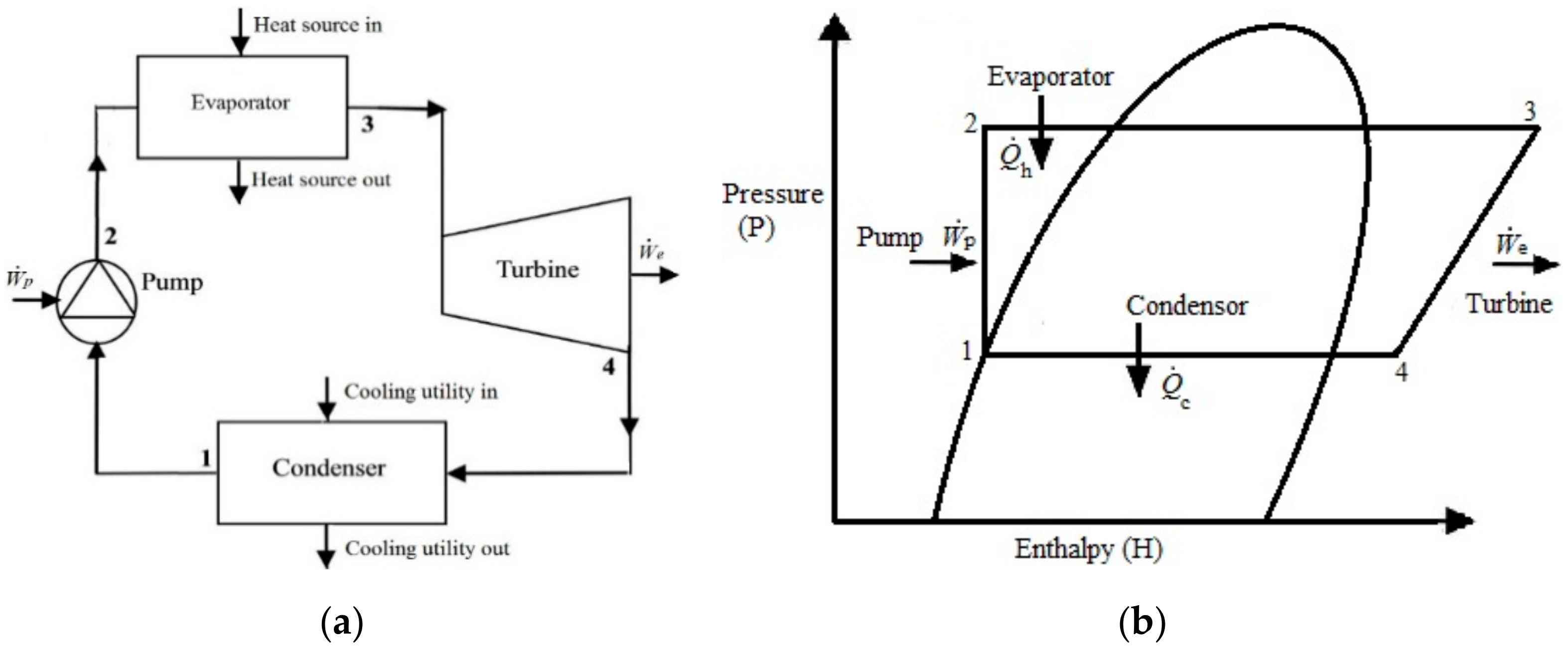
2.2. Power Cycle for Heat-To-Electricity Conversion

Electricity can be generated in power plants based on Rankine cycles by extracting thermal energy from a high temperature/pressure steam (upwards of 400–500 °C) using steam turbines. However, when organic fluids are used in ORC engines, which have lower boiling points and higher vapour pressures compared to water, efficient operation at temperatures as low as 70 °C is possible ([9], p. 26). For example, the ORC power plant installed at Chena Hot Springs in Alaska has been known to generate power from a geothermal hot-water source with temperatures as low as 73 °C [27,28].
The working principle of ORCs is the similar to that of conventional Rankine cycles, with the exception that organic fluids undergo Rankine heat-engine cycles to generate electricity from lower temperature heat sources such as industrial waste heat, geothermal energy, biomass combustion, and solar energy [32,33,34,35,36,37]. In these systems, the working fluid is pumped to a high pressure, where it absorbs heat from the heat source in an evaporator. Following evaporation, the fluid is then expanded to generate power, and sent to a condenser where it releases heat to a heat sink. A schematic diagram of a simple ORC layout and a corresponding thermodynamic cycle is shown in Figure 1.
Hammond and Norman [16] considered the minimum electrical power output for a viable waste heat-to-electricity conversion project and stated that this is around 0.5 MWe, and that based on currently available technology, the temperature band within which ORC systems can successfully utilize waste heat is 100–500 °C [12,16,38]. When operating within these limits, the capital costs of ORC-based power-generation systems have been estimated to be between 1000 and 2000 £.kWe−1 [2,39,40].
The thermal efficiencies of such ORC power-generation systems depend on various factors, including the heat source and sink temperatures (which also determine the choice of an appropriate working fluid), the type of turbine technology used, the quantity of waste heat that is recovered and utilized (which sets the size of the system), the system’s architecture (e.g., whether it includes regeneration or otherwise), etc. Since ORC systems operate at lower temperatures than conventional Rankine cycles, their thermal efficiencies are inherently lower. Various sources report efficiencies of ORC systems that vary from about 10% to 25% in the temperature range of 100–400 °C [38,41,42].
The use of ORC engines specifically in petroleum refineries has been previously considered (e.g., in Ref. [43]). Mechanical Technology Inc. [44] described the construction and showed test results of a prototype ORC engine capable of generating 1 MWe of electricity for use in a refinery in the US. Although the exact heat source for this particular application was not clearly specified, it can be presumed that the ORC engine was designed to recover waste heat from the product streams that are currently being cooled by air-cooled heat exchangers. In Ref. [44], the authors state that the refining sector has the largest potential for the penetration of ORC technology. Furthermore, Berntsson et al. [45] performed an economic evaluation of the use of an ORC engine at the Lysekil refinery in Sweden and concluded that it would be uneconomical to install this at the prevalent cost of electricity in Sweden, i.e., that the capital expenditure is not commercially viable without subsidies or other incentives. In another interesting study at the University of Pannonia in Hungary [46], the performance of a large-scale ORC system was simulated when recovering and utilizing 32 MW of low-grade heat from a refinery source while considering a range of operating fluids, with estimated payback times of six-to-seven years. In related work, Mitsuo, Silva and Oliveira [41] performed technoeconomic studies of the cooling of diesel streams in refineries with a medium-sized heat load (enthalpy flow-rate) of 2.4 MW using an ORC engine and concluded that recovering and re-using this energy with heat exchangers was more economical compared to using ORC systems to convert this energy to electricity. At an even smaller scale, Jung, Krumdieck and Vranjes [40] undertook a technoeconomic analysis of a 250 kWe ORC system using heat from a kerosene cooler in a vacuum distillation unit located at a refining complex in New Zealand. Their study showed a reasonable internal rate of return (IRR) of 21.8% and a payback of six-to-eight years. The estimated investment was around USD 3000 per installed kWe.
In one example of the implementation of ORC technology in actual refining applications, Fuji Oil Company [47] installed an ORC power generation system at its Sodegaura refinery plant, which utilizes heat available at temperatures up to 115 °C from the top of the plant’s distillation column, thereby recovering waste heat that would have been released into the atmosphere if a conventional air-cooled heat exchanger were employed. In another example at a chemical manufacturing plant, DRD Power [48] reported on a portable ORC module that was built and commissioned in Greatham, UK, that is capable of generating 130 kWe of electricity using heat at temperatures around 90 °C.
Other alternative technologies for low-grade/external heat-to-electricity conversion, e.g., Kalina cycles [49,50,51,52], trans/supercritical CO2 cycles [53,54,55], trilateral/flash cycles [23,56,57,58], as well as thermoacoustic/fluidic devices [59,60,61,62,63,64,65,66,67,68,69], are excluded from the present study as they are considered less technically and/or commercially mature in the context of the chosen application (including the specific temperatures, scales, etc.). Thermofluidic oscillators, in particular, are a promising option at small scales, but are in the early stages of development. Similarly, there are few reports concerning the implementation of Kalina cycle waste-heat plants worldwide. In fact, although Kalina cycle power-plants are suitable when using heat sources such as geothermal energy, they are not generally recommended in waste-heat recovery applications due to their more aggressive operating conditions, complexity of construction, and ultimately higher installation costs [49]. Even though Kalina plants have shown improved thermodynamic performance (i.e., efficiencies) compared to ORC systems [50,51,70,71], these benefits are often, but not always, marginal (typically <5–10% higher efficiency) and can be outweighed by the aforementioned disadvantages in waste-heat conversion [49,72].

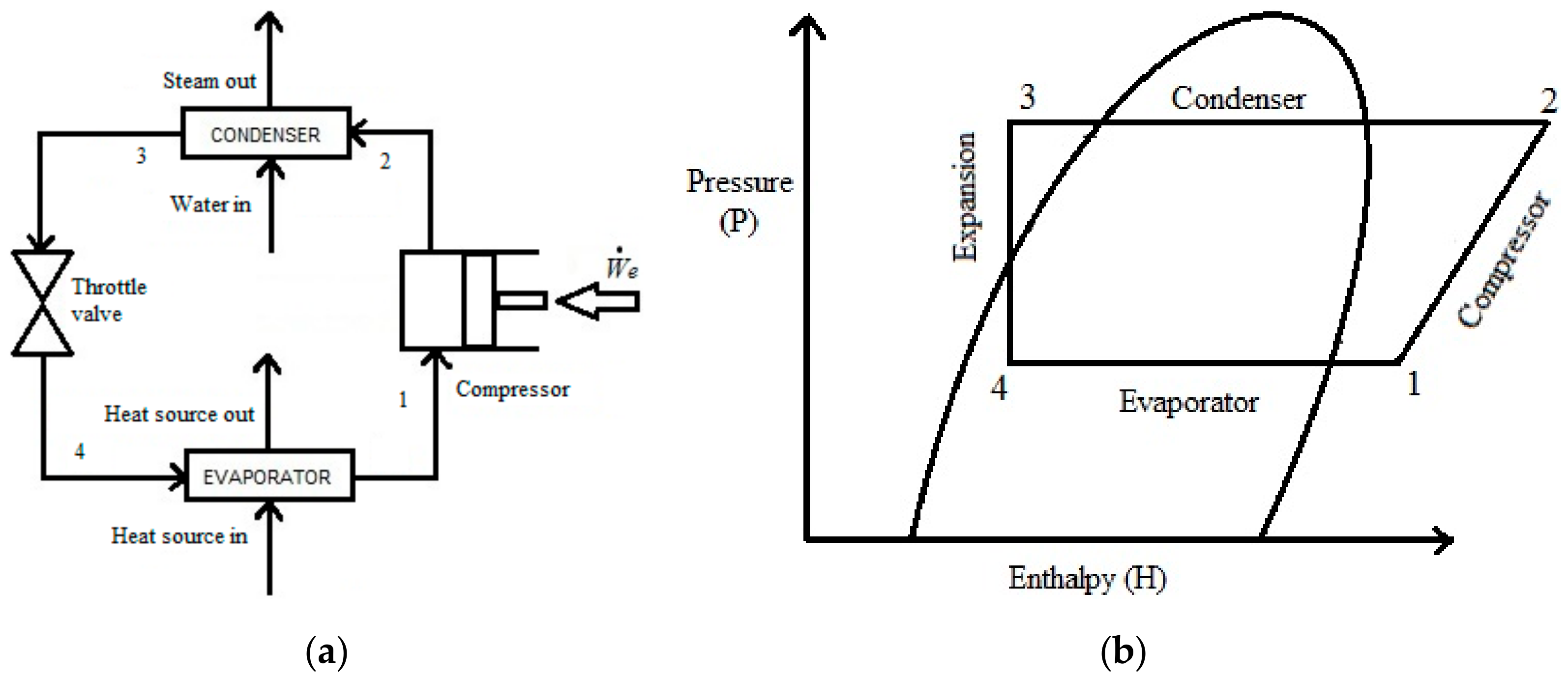
2.3. Heat Pumps for Temperature Upgrading

Heat pumps use external energy to drive a cycle that absorbs heat at a low temperature and rejects heat at a higher temperature, thereby ‘upgrading’ heat to a higher (and more desired) end-use temperature. The present paper is concerned, in particular, with MVC heat pumps [9]. Modern heat pumps can provide temperature lifts of up to 50 °C [12], and efforts are in place to develop even high-temperature systems. The capital costs of heat pump systems are lower than for ORC engines, being in the range from £150 to £200 per kWth of heat delivered [2].
In a compression-based heat pump, the working fluid absorbs low-grade heat in an evaporator (from the heat source) to evaporate. The fluid is then compressed, thereby increasing its saturation temperature/pressure, and sent to a condenser where it releases heat to a higher-temperature heat sink. The fluid is then throttled and sent to the evaporator to close the cycle. In an absorption-based heat pump, the compressor is replaced by separate absorption/desorption processes that establish high and low partial-pressure levels that drive the heat addition and rejection. A schematic diagram of a simple MVC layout and a corresponding thermodynamic cycle is shown in Figure 2.
The integration of heat pumps in refineries is not commonplace; nevertheless, the use of heat pumps has been reported in multiple industrial applications where a cooling/chilling demand exists. Berntsson et al. [45] performed a preliminary analysis of large-scale heat pump capable of delivering 20 MWth by using low-grade heat available in the Preem refinery based in Sweden. This analysis indicated a payback period of two-to-four years based on the prevalent local prices of electricity and steam; however, a detailed analysis of the capital expenditure required is required to substantiate the claim. Cao et al. [73] modelled a mechanical vapour compression heat pump and its variants using a waste-heat source from an oil field at 45 °C to heat up water from 70 to 90 °C. Their analysis suggests that simple heat pump cycles are not economically feasible, but also that modified forms of heat pumps can have payback periods of four-to-five years.
A classic example of the use of heat pumps is in a petrochemical plant separating a mixture of C1–C5 species, wherein the reboiler and condenser operate at very low temperature levels. The heat is transferred from the condenser to the reboiler by using a heat pump [74].

3. Theoretical and Empirical Models of Heat Engines and Heat Pumps

3.1. Heat Engines

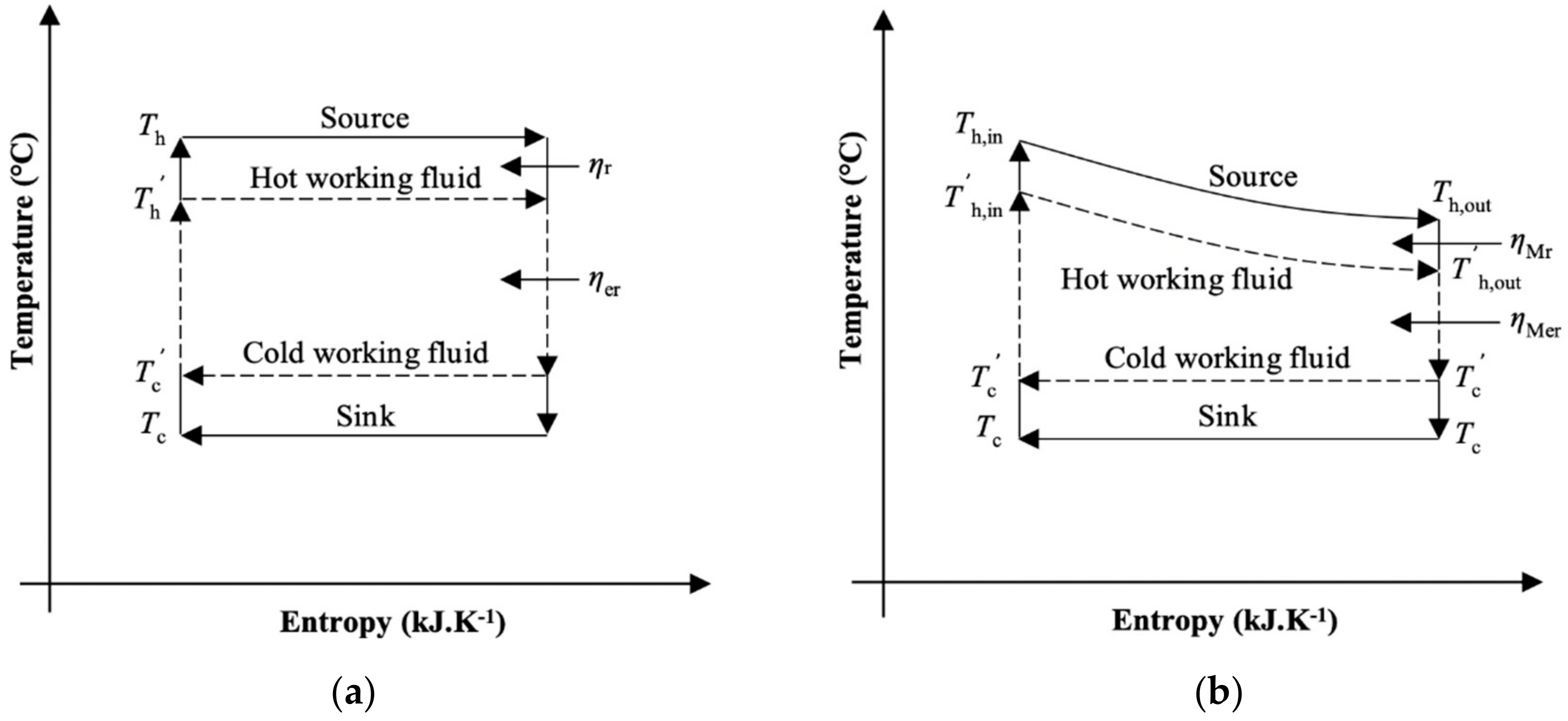
3.1.1. Reversible (Carnot) and Endoreversible (Novikov) Heat Engine

In the Carnot heat engine, the heat addition and heat rejection processes take place at constant temperatures, while the working fluid maintains a zero temperature-difference with the heat source and sink that also remain at a constant temperature. All processes/components are ideal, and the operation of heat engine is therefore fully reversible. No heat engine can be more efficient than a Carnot engine operating between the same thermal reservoirs, and in this sense, the Carnot efficiency is the maximum efficiency attainable by an ideal heat engine when operating between these reservoirs, thus forming a useful performance benchmark for other heat engines (or cycles). The thermal efficiency of the Carnot engine, defined as the (net) work output over the heat input, is given by:
η r = 1 T c T h .
In an endoreversible heat engine, the heat transfer (addition/rejection) processes remain irreversible (as above) due to non-zero temperature differences between the working fluid and external heat source/sink that drive heat into and out of the engine cycle, whereas all other processes/components are thermodynamically ideal (reversible). Similarly to the Carnot engine, an endoreversible engine assumes that the working fluid temperatures during heat addition and rejection remain constant, as do the heat source and sink temperatures. The thermal efficiency of an endoreversible (Novikov) engine is derived by identifying the heat addition and rejection temperatures that maximize the (net) work output from the engine for given source and sink temperatures; this efficiency is given by the expression:
η er = 1 T c T h .
The net power generated in both reversible (Carnot) and endoreversible (Novikov) cases is given by:
W ˙ e , net = η m ˙ c p hot T h , in T h , out ,
where η = η r   or   η er , as appropriate (‘r’ signifying reversible and ‘er’ endoreversible engines).

3.1.2. Varying Heat-Source Temperature Heat Engine

The assumption that the heat-source temperature remains constant through the evaporator is not realistic. On the other hand, access to enough cooling is assumed such that the heat sink is still considered to remain at a constant temperature. To account for the fact that the heat-source temperature will drop as heat is transferred to a heat engine during the heat addition process, one can use the relations in Equations (5)–(7), based on the analysis by Markides [49,75], in which infinitesimal Carnot heat engines were integrated over a changing heat-source temperature to derive expressions for the total net power ( W ˙ e , net ) generated.
For varying source temperature reversible heat engine (referred to as “Mr engine”):
W ˙ e , net m ˙ c p hot T h , in = 1 b + T o T h , in ln b .
For varying source temperature endoreversible heat engine (referred to as “Mer engine”):
W ˙ e , net m ˙ c p hot T h , in = 1 b 2 c 1 b ,
where b = T h , out T h , in and c = T o T h , in .
A thermal efficiency can then be evaluated as:
η = W ˙ e , net ( m ˙ c p ) hot ( T h , in T h , out ) ,
where η = η Mr for the ‘Mr’ heat engine and η = η Mer for the ‘Mer’ heat engine.
Equation (2) states the thermal efficiency of the reversible (Carnot) cycle, which is defined in relation to the solid lines in Figure 3a, whereas Equation (3) states the thermal efficiency of the endoreversible (Novikov) cycle, which is defined in relation to the dashed lines in Figure 3a.
Similarly in Figure 3b, the cycle described by the solid lines corresponds to the Mr engine (reversible engine with varying heat-source temperature), whereas that described by the dashed lines (endoreversible engine with varying heat-source temperature) corresponds the Mer engine; both thermal efficiencies are given by Equations (5)–(7).

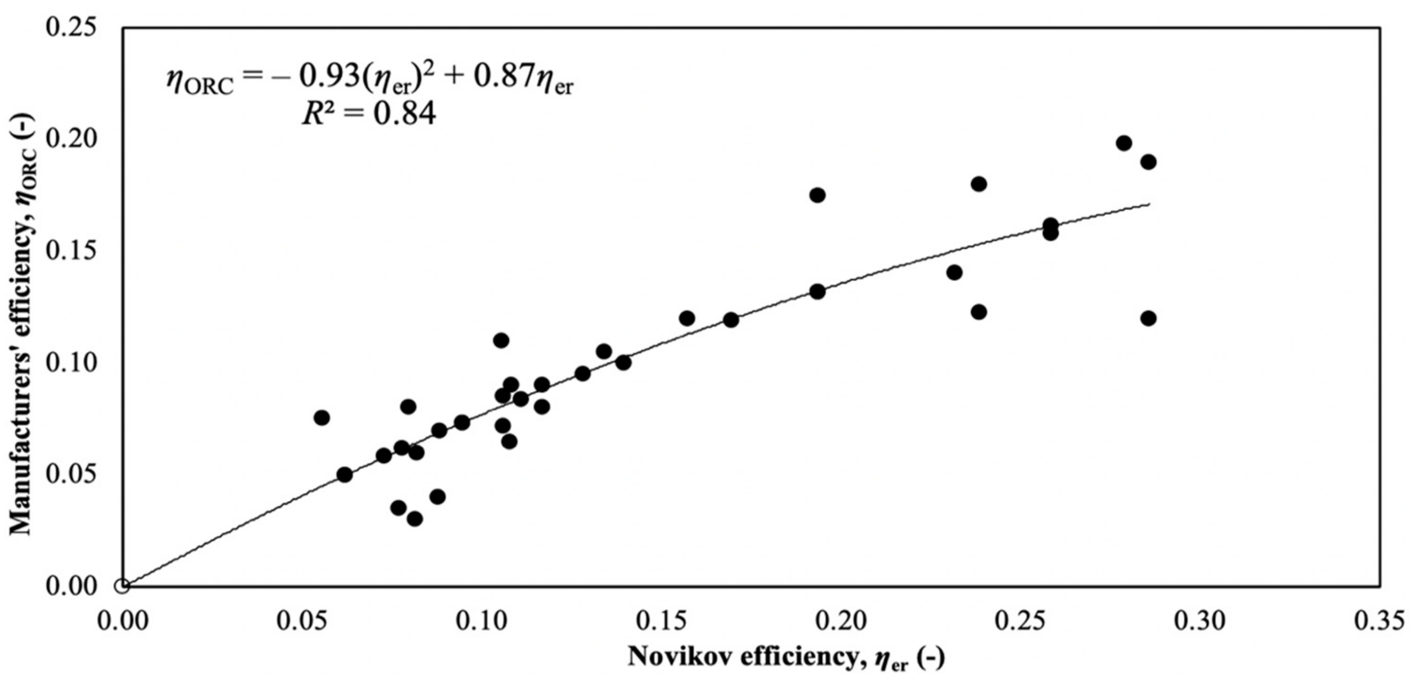
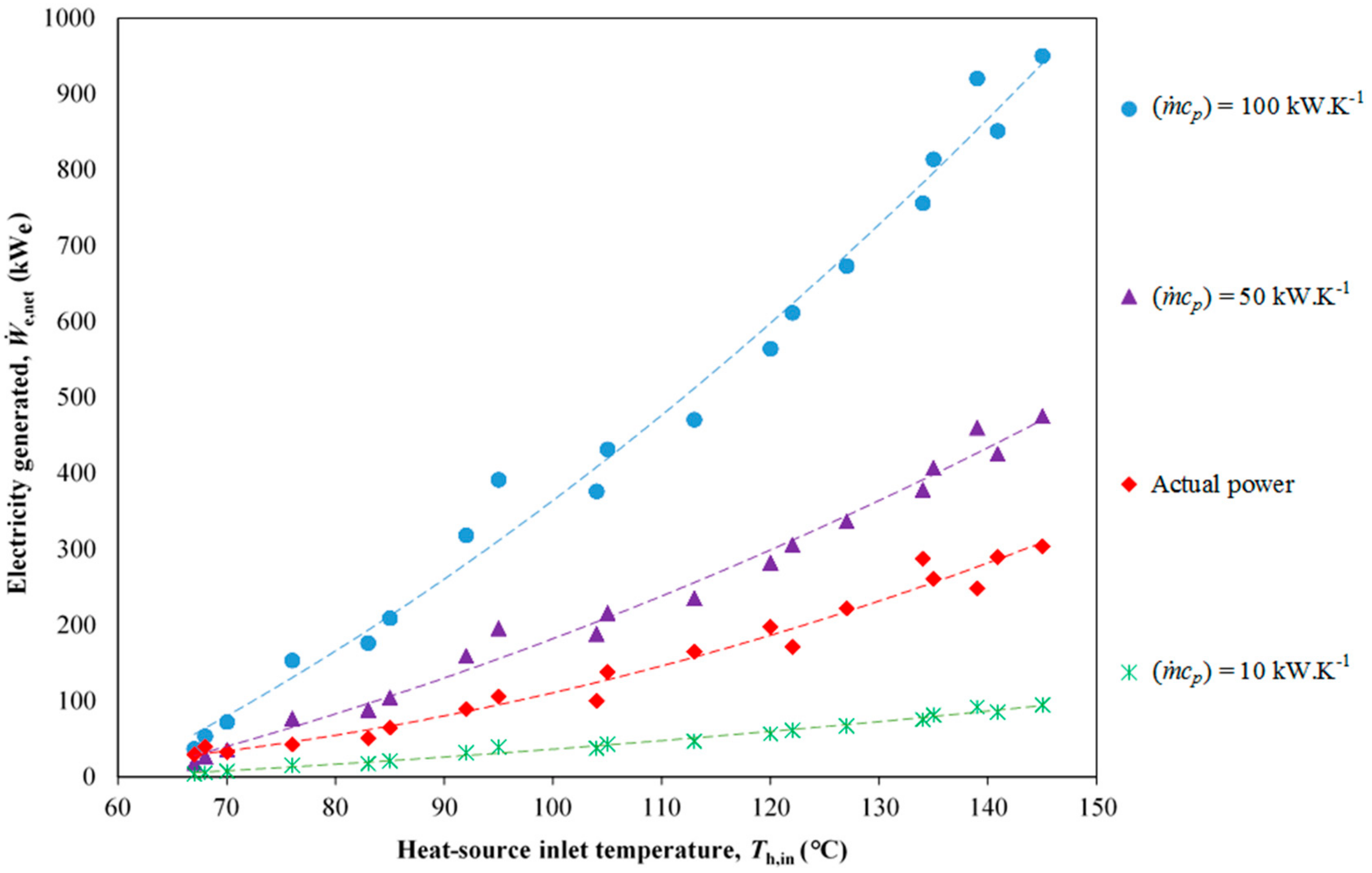
3.1.3. Practical ORC Engine Efficiencies

In order to estimate the amount of electricity that can be generated by an ORC engine, a survey was undertaken of the thermal efficiencies of 34 commercial ORC engines reported by manufacturers in product datasheets. Since in many cases there is an absence of information in such datasheets on the source characteristics that would allow an evaluation of Equation (7), these reported efficiencies were compared (see Figure 4) to the theoretical efficiencies predicted for an endoreversible (Novikov) heat engine with the same input heat-source temperature, T h , in , and sink temperature. This eliminated the need to provide information on the heat-source temperature variation through the engine. An empirical relationship was then obtained between the efficiency of commercial ORC engines and the Novikov prediction/estimate, which is given by Equation (8) below and also shown in Figure 4:
η ORC = 0.93 ( η er ) 2 + 0.87 η er .
Predictions from this relationship have an absolute standard error of 0.14 based on the standard deviation of the differences between manufacturer-quoted efficiencies (Figure 4) and predictions from Equation (8), and a relative error of 15% based on the average relative difference between the same quoted and predicted efficiencies. The net electrical power that can be generated by ORC engines is:
W ˙ e , net = η ORC m ˙ c p hot T h , in T h , out .

3.2. Heat Pumps

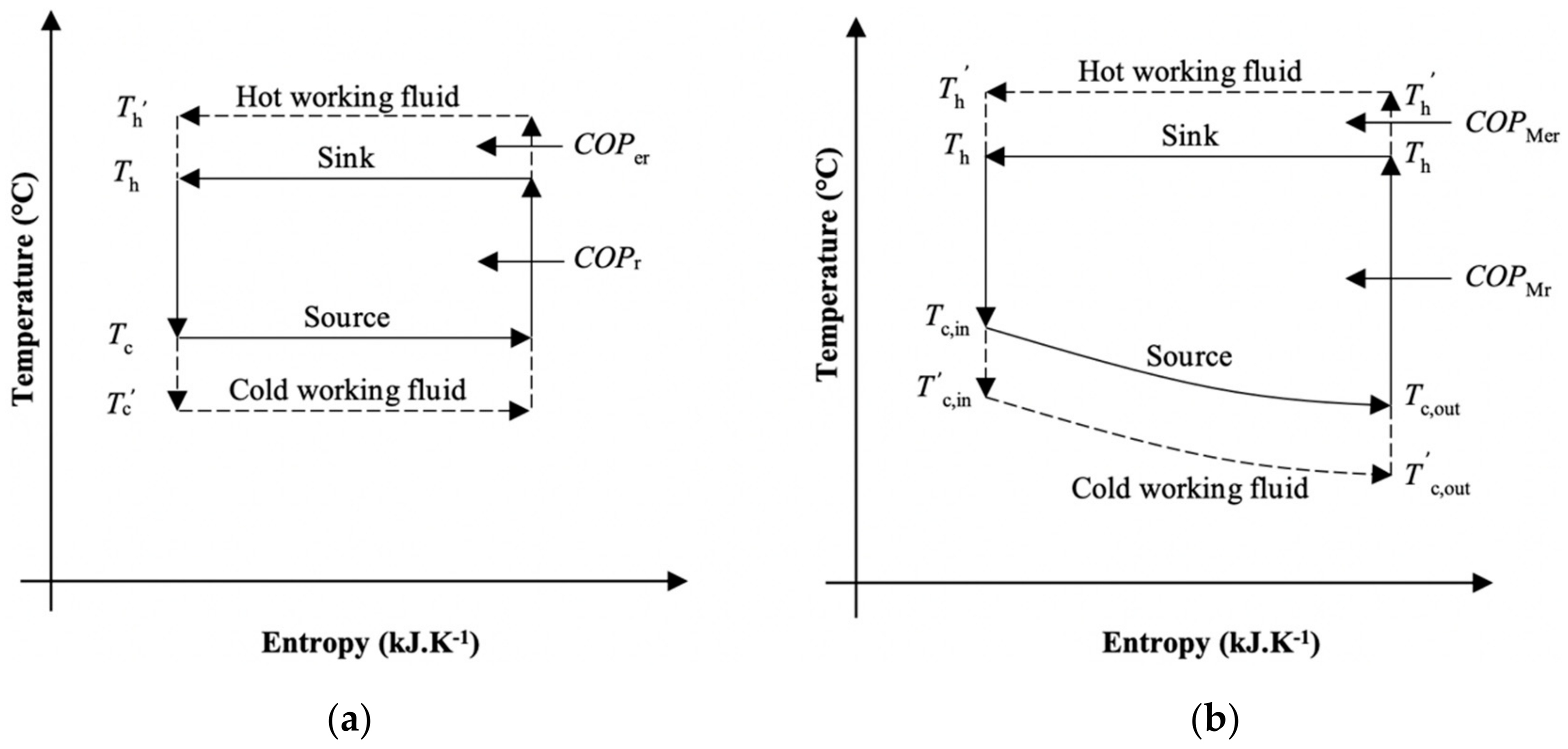
3.2.1. Reversible (Carnot) and Endoreversible Heat Pump

The ideal (Carnot) heat pump has constant temperature heat addition and rejection processes that take place at the (constant) temperatures of the external heat source and sink, respectively, and fully reversible operation. No heat pump can have a better performance than a Carnot heat pump operating between the same thermal reservoirs. The coefficient of performance (COP) of the Carnot heat pump, which is the heat supplied to the high-temperature sink over the (net) work input, is given by:
COP r = T h T h T c .
In an endoreversible heat pump, the heat transfer processes are irreversible due to non-zero temperature differences between the working fluid and the external heat source and sink, which drive heat into and out of the heat pump cycle; all other components/processes are thermodynamically ideal (reversible). As with the Carnot heat pump, the endoreversible heat pump assumes that the heat source and sink temperatures, as well as the working fluid temperatures during heat addition and rejection, all remain constant. Various expressions for the COP of an endoreversible heat pump have been derived for different temperatures of the working fluid during heat addition and rejection. In this work, various expressions were checked (details in Section 4.1) before the expression by Blanchard [76] was selected as this gave the best match with the COP of reported practical heat-pump systems; this is given by:
C O P er = 1 T c T h + T k 1 ,
where Tk is a parameter with units of temperature based on assumptions made for the heat transfer processes, including the thermal conductance ratio, between the working fluid and the (hot and cold) heat reservoirs. Blanchard [76] recommended a value of Tk = 30 °C.

3.2.2. Varying Heat-Source Temperature Heat Pump

To account for the drop in the temperature of a low-temperature or ‘cold’ heat source (notwithstanding phase change) as it transfers heat to a heat pump (which then delivers heat to a high-temperature or ‘hot’ sink; here for steam generation and assumed constant), one can integrate infinitesimal Carnot heat pumps across this changing temperature difference in a similar manner to that done for heat engines in Refs. [49,75]. This leads to the following relationships for a reversible heat pump (referred to as “Mr heat pump”):
Q ˙ hot = m ˙ c p cold T h ln T c , in T c , out ,
Q ˙ cold = m ˙ c p cold T c , in T c , out ,
W ˙ e = Q ˙ hot Q ˙ cold ,
C O P Mr = Q ˙ cold W ˙ e .
Extending the above analysis to endoreversible heat pumps, the following expressions are obtained for the case of a varying heat-source temperature (referred to as “Mer heat pump”):
Q ˙ hot = m ˙ c p cold T h + T k ln T c , in T c , out ,
Q ˙ cold = m ˙ c p cold T c , in T c , out ,
W ˙ e = Q ˙ hot Q ˙ cold ,
COP Mer = Q ˙ hot W ˙ e .
Equation (10) is the COP of the heat pump cycle denoted by the solid lines in Figure 5a, and Equation (11) is the COP of the cycle denoted by the dashed lines in same figure. The Mr heat pump is described by the solid lines in Figure 5b, and the Mer heat pump by the dashed lines in the same figure.

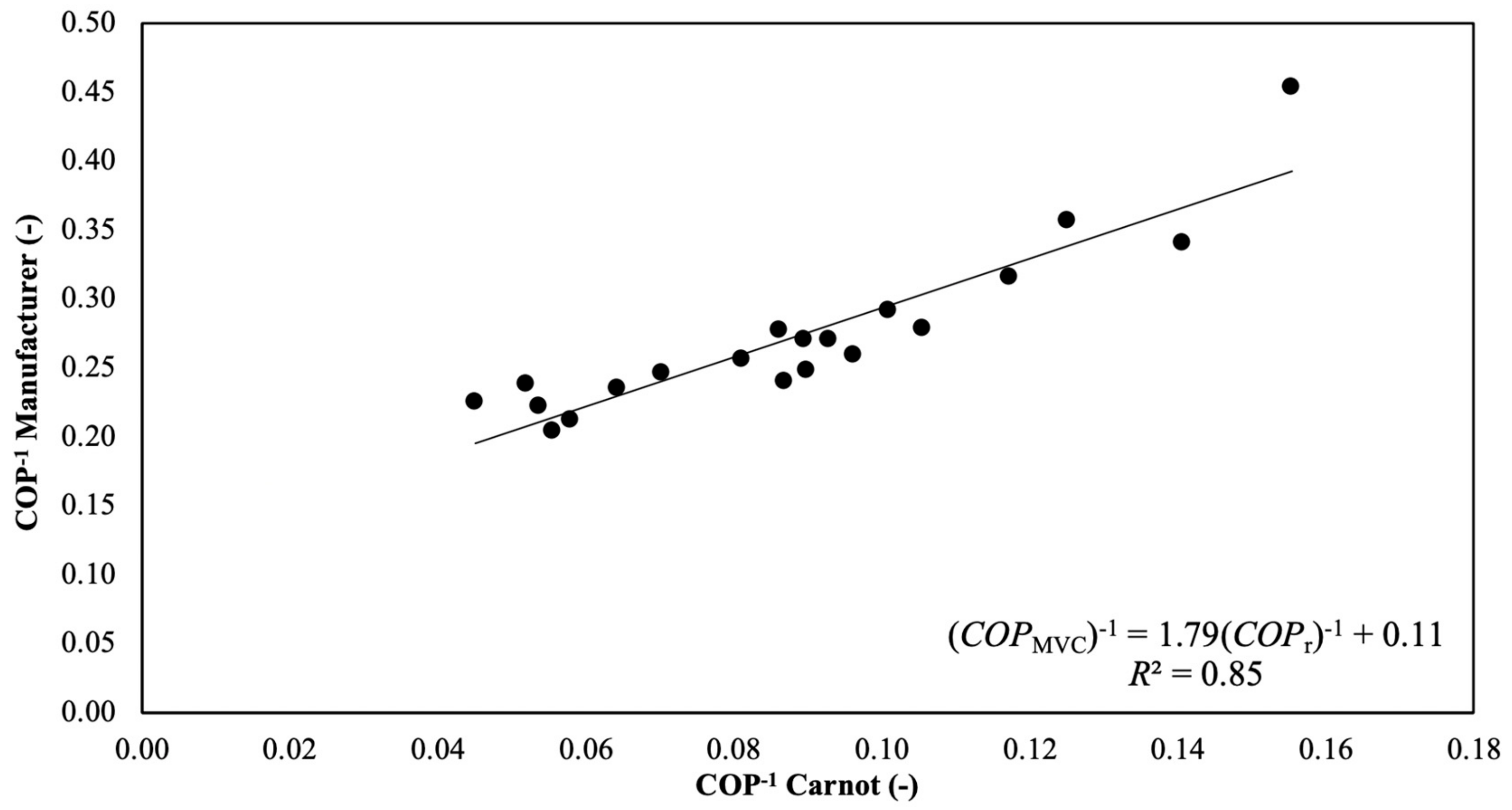
3.2.3. Practical COPs of MVC Heat Pumps

In order to estimate the expected amount of thermal energy that is delivered by a practical mechanical vapour compression (MVC) heat pump, a survey of the reported COPs of 20 commercially available heat pumps was performed. Given the absence of information in most manufacturers’ datasheets concerning the heat source characteristics that would allow an evaluation of estimated COPs from Equations (15) and (19), the reported COPs were compared to the theoretical COPs for Carnot heat pumps operating across the same heat source and sink temperatures, thus eliminating the need to know the heat addition temperature variation through the heat pump. From this comparison, an empirical relationship between COP of commercial MVC heat pump and Carnot heat pump was obtained; this is given by Equation (20) below and also shown in Figure 6:
( C O P MVC ) 1 = 1.79 ( C O P r ) 1 + 0.11 .
Similarly to Equation (8), predictions from Equation (20) have an absolute standard error of 0.18 based on the standard deviation of the differences between manufacturer-quoted COPs (Figure 6) and predictions from Equation (20), and a relative error of 6% based on the average relative difference between the same quoted and predicted COPs. Various other measures that have been proposed [77,78,79,80] for the COPs of endoreversible heat pumps were analysed in a similar manner to Equation (11) so as to identify the one whose predicted values were closest to the empirical data fit of Equation (20).
As elaborated further in Section 4, it was observed that when a modified parameter:
T k = T k 0 + ( T c , in T c , out ) ,
is used in the Blanchard equation, with Tk0 = 105 °C, theoretical COP predictions from Equations (16)–(19) exhibit the lowest deviations from predictions made from Equation (20).

3.3. Economics of Low-Grade Heat Recovery Using ORC Engines and MVC Heat Pumps

It is assumed that all electricity generated using an ORC engine is consumed onsite and thus contributes towards reducing the imported electricity from the grid, thereby reducing utility costs. An annualized capital expenditure can be calculated by assuming that the capital investment for installing an ORC engine is financed completely by external borrowing. The annualized capital expenditure (ACE) and the net annual monetary benefits (AB) arising from the use of ORC engines are given by Equations (22)–(25) (all quantities are defined in the Nomenclature section):
S A E = W ˙ e n C e ,
A F = i ( 1 + i ) n + i ,
A C E = ( A F ) ( C C ) ,
A B = S A E A C E .
The monetary benefits associated with the use of a heat pump are dependent on both the price of the heating fuel that is displaced from its use, and the price of electricity that it requires for operation. Specifically, in the present work, the heat pump is envisaged to raise steam, thus directly displacing heating fuel, which is assumed to be otherwise consumed in a gas-fired boiler with an efficiency of 90%. The commercial benefits arising from the use of heat pumps are evaluated as follows (again, all quantities are defined in the Nomenclature section):
S S G = Q ˙ hot 0.9 n C g ,
E E C = W ˙ e n C e ,
A B = S S G E E C A C E .
The payback period for each case (ORC engine or MVC heat pump) is the calculated as the ratio of respective capital cost (CC) to the annualised benefit (AB):
P B P = C C A B .
The main assumptions made in relation to the capital costs, costs of electricity, gas and steam, operating hours and interest rates are stated in Appendix A. The models presented in Section 3.1 (ORC engines) and Section 3.2 (MVC heat pumps) were applied to a sample of published multiple low-grade waste-heat streams rejecting heat to air or water (listed in Table 5), in order to establish ranges of temperature and thermal-energy content of waste-heat streams for which either MVC heat pump systems or ORC engines would be preferred. In this table (i.e., Table 5), and in the remainder of this paper, thermal-energy content is defined as the change of the enthalpy flow-rate of the heat-source stream across the reported temperature difference, Q ˙ = Δ H ˙ .

4. Results and Discussion

4.1. Comparison of Theoretical Models against Empirical Predictions

Figure 7 shows ORC engine efficiency predictions from the various thermal efficiency definitions (developed in Section 3.1), for the low-grade heat streams listed in Table 5, as a function of the heat-source inlet temperature of each engine. Each point in the figure represents one of the 19 entries in Table 5. The curve fitted to the 19 points for each efficiency prediction method gives a representation of the predictions over the range of heat-source temperatures (Th,in) in Table 5. In Figure 7, the empirical efficiency curve ( η ORC ) for ORC engines obtained from regression of manufacturers’ data is also plotted. From the figure, it can be observed that the predictions from the empirical model ( η ORC ) closely match the predictions of the Mer engine efficiency model η Mer . The percent differences between these two efficiency measures has a mean of 5.4% and a standard deviation of 3.6%. On the other hand, the reversible (Equation (2)) and endoreversible (Equation (3)) heat-engine predictions significantly overestimate the commercial ORC engine performance. Although this was expected, it was nevertheless interesting to quantify these deviations for the data considered in the present work because it reveals the level of error associated with using these well-known estimates, which are common in the literature. Figure 7 suggests that these expressions overestimate performance, in terms of the mean difference between the predictions and actual data, by a factor of 1.46 (reversible) and 30% (endoreversible). These efficiency expressions should therefore be used with caution and only if this level of accuracy is deemed acceptable.
Figure 8 shows the electrical power generated by ORC engines utilizing the thermal energy available in the streams listed in Table 5 (“actual power” points and curve). It also shows estimates of the power produced by ORC engines utilizing thermal energy from low-grade heat streams with same temperature differences as in Table 5, with heat capacity rates ( m ˙ c p ) = 10 kW.K−1, 50 kW.K−1 and 100 kW.K−1. This chart can be used to estimate quickly the range of electrical power outputs that can be generated from the recovery and conversion of low-grade heat streams using ORC engines.
For the various theoretical MVC heat pumps models derived in Section 3.2, Figure 9 shows heat-pump COP predictions as a function of the heat-source inlet temperature when utilizing the available thermal energy in the streams listed in Table 5 to generate steam at 150 °C (low-pressure (LP) steam). The figure also shows the COP predictions from the empirical model (Equation (20)) obtained from the regression of commercial data. Compared to the case of ORC engines in Figure 7, the match of the COP predictions from the empirical model is close to the theoretical predictions from the Mer heat-pump. The match is not as good as for the ORC engine results (in the earlier figures), but is nevertheless acceptable. The percent difference between the two COPs has a mean of 14.8% and a standard deviation of 8.8%. Similarly to Figure 7 for the ORC engines, the reversible and endoreversible performance predictions substantially overestimate actual performance by factors of 2.87% and 83%, respectively.
It was mentioned above that Equation (21) was found to be valid for Tk0 values greater than 85 °C, and the maximum ΔT of the heat streams listed in Table 5 is 84 °C. The COP prediction by the Mer heat pump (endoreversible heat pump with a source-varying temperature) is a strong function of Tk, which in turn is a function of the temperature difference between the thermal reservoirs and the working fluid of the heat pump, the ratio of thermal conductances between the heat reservoirs and the working fluid, and the ΔT of the cold stream. It can be observed that for streams with temperature lifts lower than 40 °C, the deviations between theoretical Mer and empirical COP predictions is less than 0.6. However, when the temperature lifts are higher than 40 °C, the deviations are greater than 0.6. This suggests that when the temperature lifts are small, the temperature difference between the heat pump working fluid and the heat source is also small, as expected, giving rise to small deviations between the two predictions. Conversely, when the temperature lifts are greater, the temperature difference is also greater, leading to greater deviations.
Figure 10 shows the quantity of low-pressure (LP) steam generated by MVC heat pumps utilizing the thermal energy available in the streams listed in Table 5. It also shows estimates of the steam produced by MVC heat pumps that utilize thermal energy from low-grade heat streams with the same temperature differences as in Table 5, but with heat capacity rates ( m ˙ c p ) = 10 kW.K−1, 50 kW.K−1, and 100 kW.K−1. This figure can be used to estimate quickly the range of steam flow rates that can be generated from various low-grade heat streams using MVC heat pumps.

4.2. Economics of Low-Grade Heat Recovery and Utilization

The monetary benefits resulting from the generation of electricity or steam by utilizing (converting or upgrading, respectively) low-grade heat are strongly dependent on the sink temperatures. In the case of electricity generation with ORC engines, it can be seen from Figure 11 that for the heat-sources considered here (see Table 5), the annual monetary benefits decrease by £10,000–20,000 per year when the sink temperature increases by 20 °C, from 5 to 25 °C, based on the price of electricity in China. In addition, it can be seen that the monetary benefits scale linearly with the heat-source inlet temperature.
It can be observed that the monetary benefits become positive (net positive income) for streams with heat-source temperatures above about 70 °C (with a 25 °C sink). This is important, as it underscores the reason why ORC engines operating with heat-source temperatures below 70–75 °C are not available on the market, as stated in Section 1.3. The lowest source temperature for which an installation of an ORC engine has been reported is 73 °C [27,28]. For lower temperature sinks, i.e., 5 °C, the economically limiting heat-source temperature drops to about 60 °C.
For the heat-source cases in Table 5, the generation of LP steam at 150 °C is found to have higher annual monetary benefits (by £100,000–£200,000) than the generation of medium-pressure (MP) steam at 180 °C (see Figure 12), based on the gas and electricity prices in China. The additional electricity consumed by MVC heat pumps for the generation of higher-temperature steam offsets the benefits of the higher value steam generated. Upon close inspection of Figure 9, it can be observed that COP values below 3 are obtained whenever the temperature lifts are above 50 °C. In turn, these streams give negative monetary benefits in Figure 12, i.e., the cost of electricity offsets any savings realized due to the generation of steam. Moreover, for COP values >4, temperature lifts <40 °C would be required. This implies that temperature lifts of less than 40 °C are necessary for the economically attractive operation of heat pumps under the above scenario of fuel and electricity prices in China.
In summary, based on the gas and electricity prices in the region selected here, i.e., China, LP and MP steam generation with MVC heat pumps only shows positive annual benefits for heat-source streams with temperatures above 100 and 130 °C, respectively. Unlike the case of ORC engines, it can be observed from the trend line fitted to the data points in Figure 12 that the monetary benefits arising from the use of MVC heat pumps are non-linear and rise rapidly as the temperature lifts decrease.

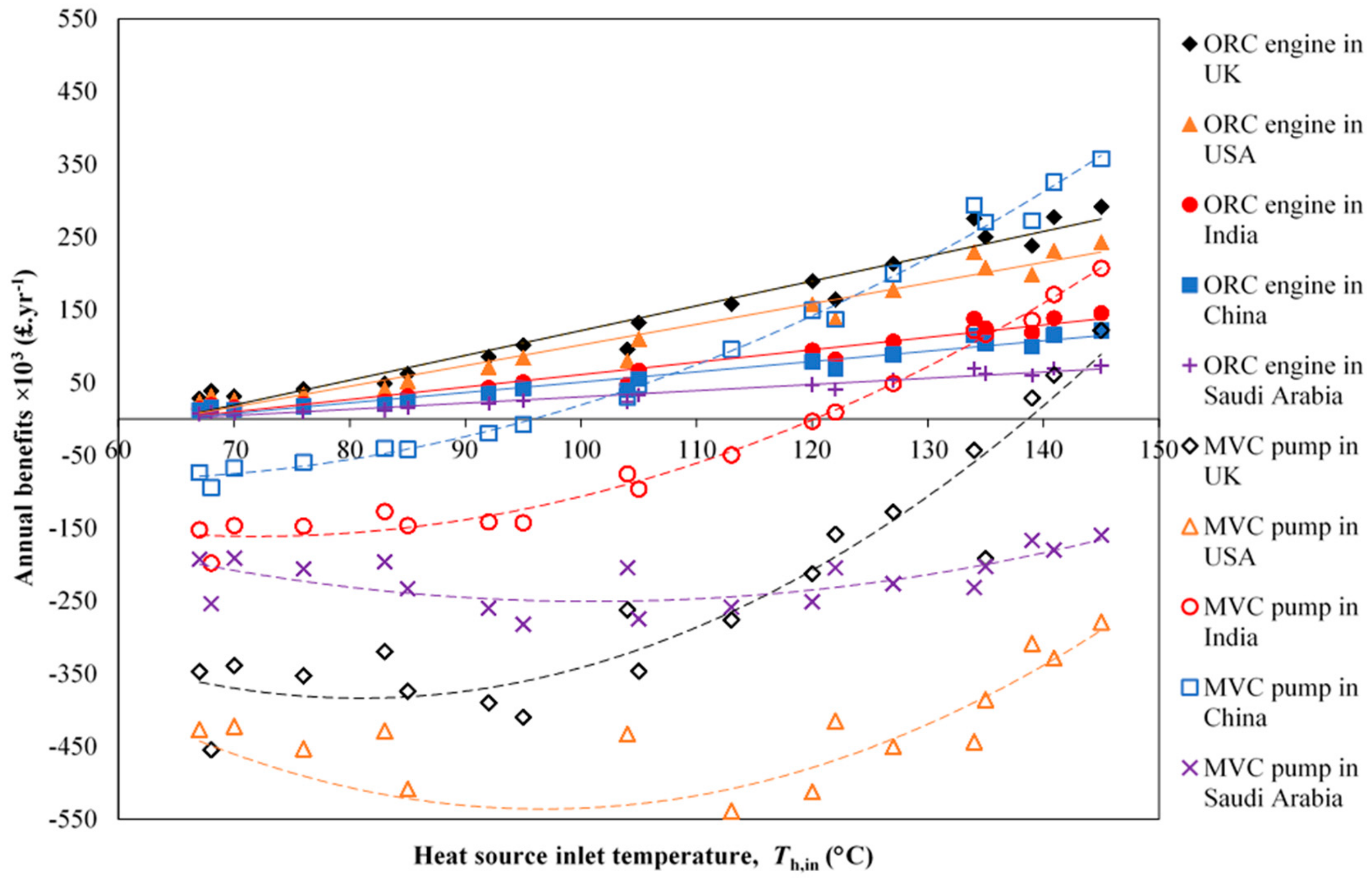
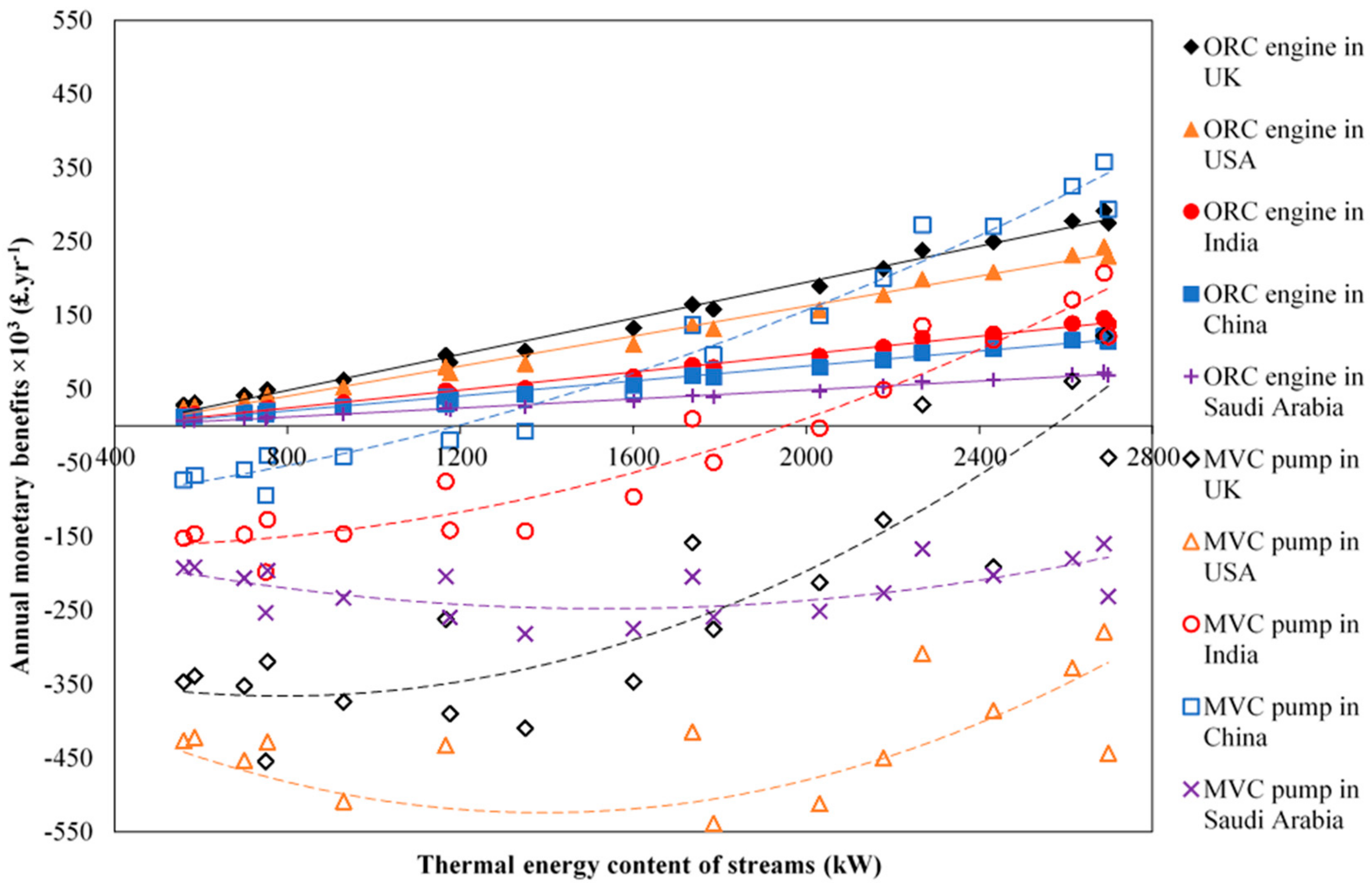
4.3. Comparison of Monetary Benefits across Global Regions

In this section, we extend our study by considering the changes to the arising monetary benefits from the implementation of the aforementioned technological solutions in a wider selection of global regions, by varying the gas and electricity prices based on figures obtained for five countries: China, India, Saudi Arabia, the UK, and the USA (Appendix A). Figure 13 shows a comparison of the annual monetary benefits, as defined in Equation (25), arising in the selected countries as a function of the inlet temperature for the waste-heat stream considered (Table 5) from the use of: (i) ORC engines to generate electricity; and (ii) MVC heat pumps to generate LP steam (at 150 °C). Similarly, Figure 14 shows a comparison of the annual monetary benefits as a function of the thermal-energy content of the same waste-heat streams. In both figures, trend lines are fitted to the series of data points in order to establish visually the crossover point above which the use of one technology would be preferred over the other.
The results reveal a huge variability in the economic feasibility of the two solutions. Although the installation of ORC engines appears to offer positive economics over the range of electricity prices and heat sources (temperatures and thermal-energy contents) considered in this work, the benefits are highly sensitive to these prices. MVC heat pump returns show a high sensitivity to the gas and electricity prices in the different countries, to the extent that in two of the countries studied here (and potentially many others that we have not considered) there is no condition under which they are financially feasible (i.e., positive monetary benefits). Based on these results, we infer that the most important criterion for business decisions regarding the choice of heat utilization option between ORC engines and, especially, MVC heat pumps does not rely on the relative thermodynamic performance of the two technologies, but rather on the prices of gas and electricity, which therefore play a crucial role in incentivising the uptake of any such technology.
For instance, under the prevalent prices of gas and electricity in China, if LP steam (150 °C) generation is of interest, the use of MVC heat pumps is economically more attractive (compared to electricity generation with ORC engines) for waste-heat streams with temperatures above ~110 °C and thermal-energy contents over 1.5 MW (from Figure 14). On the other hand, when utilizing streams with temperatures below ~110 °C and thermal-energy contents below 1.5 MW, the generation of electricity with ORC engines appears as the more economically attractive option. A similar crossover point, but at a higher waste-heat source temperature of ~135 °C and at a higher thermal content of 2.5 MW, is found to exist for India. Of particular interest is the observation that in countries such as Saudi Arabia, the UK, and the USA, the use of MVC heat pumps is never economically justified, at least, in our investigated range of streams and the explored utility prices.
For China and India, a closer inspection reveals that for waste-heat streams where the use of MVC heat pumps appears to be more attractive compared to the generation of electricity using ORC engines, i.e., above the crossover temperatures mentioned in the previous paragraph (~110 and ~135 °C, respectively), the MVC heat-pump COP values exceed 4 and the temperature lifts are below 40 °C. This, however, does not hold true for Saudi Arabia, the UK, and the USA, where the use of MVC heat pumps does not appear promising. A COP value of 4 thereby seems to be a necessary but not sufficient condition for establishing whether or not the use of MVC heat pumps are preferred over the use of ORC engines in heat recovery projects.
Proceeding further, a comparison of the payback periods associated with the use of ORC engines and MVC heat pumps is shown in Figure 15 and Figure 16. As above, fitted trend lines are used to easily identify (approximately) the crossover point above which the use of one technology might be preferred over the other in the countries examined; they do not suggest a particular functional relationship.
In these figures, the results indicate that the payback periods of ORC engine projects in the UK and the USA can be below three years, making low-grade waste-heat recovery for generating electricity commercially viable. In China and India, the payback periods for the ORC engines are found to lie in the range of four-to-five years, making them commercially feasible but less attractive. For waste-heat streams at temperatures above 120 and 140 °C, for China and India respectively, investing in MVC heat pumps becomes an interesting option. Extrapolation of the data suggests increasingly shorter payback periods (below two years) at higher heat source temperatures, at which point steam generation with MVC heat pumps becomes particularly attractive. As a consequence of the low price for energy (fuels, electricity) in Saudi Arabia, the payback time in Saudi Arabia of over eight years makes investments in low-grade waste-heat recovery with ORC technology unlikely, while the installation of MVC heat pumps is found to never pay back the initial investment.

5. Conclusions

The recovery of low-grade heat from waste-heat sources typically found in the refining sector, followed by either thermal-energy conversion (with ORC engines) or upgrading (with MVC heat pumps), specifically comparing onsite electricity or steam generation in a range of countries with different gas and electricity prices that has been performed this study, leads to several key conclusions concerning the deployment of these technologies, as follows:
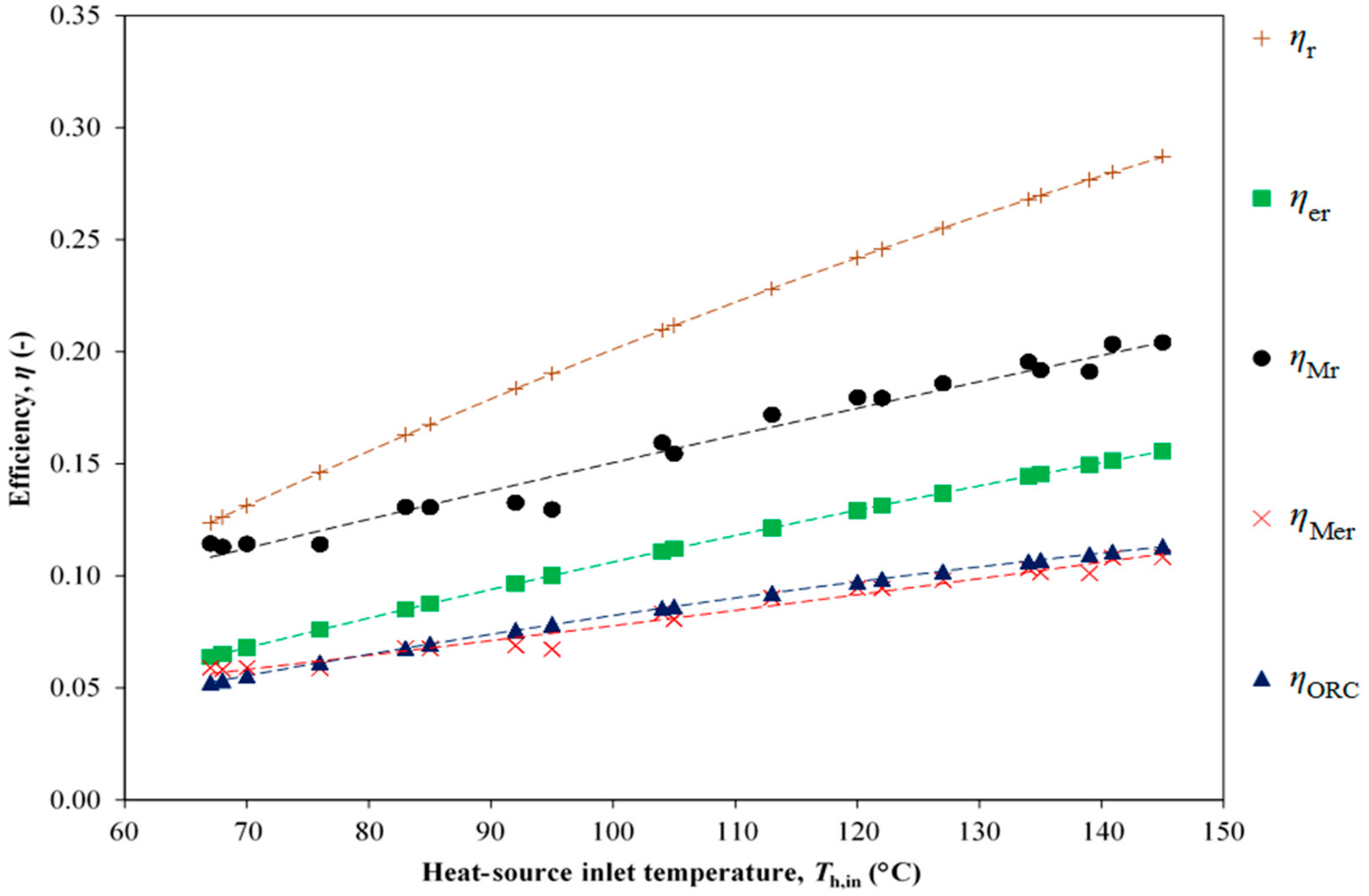
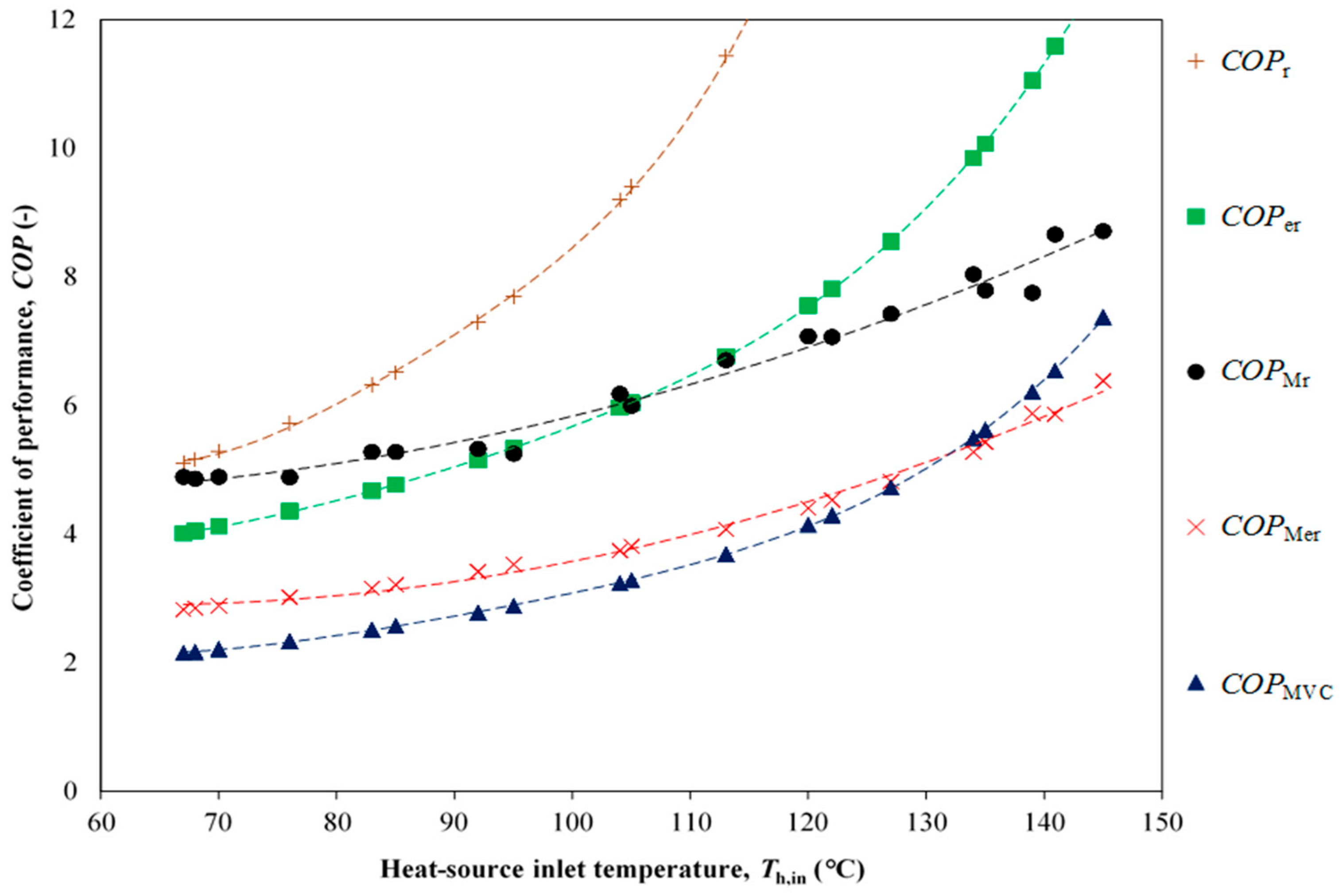
  • Data from manufacturers on ORC engine thermal efficiencies and MVC heat pump COPs can be used to derive empirical relationships for predicting the performance of these technologies. In this work, expressions were derived for heat engines (Equation (8)) converting heat sources with temperatures up to 330 °C to electricity, as well as heat pumps (Equation (20) upgrading heat by temperature lifts up to 80 °C, that can predict actual performance within 4% for the former and 8% for the latter.
  • The thermal efficiencies of commercially available ORC engines are well represented by a theoretical expression derived for an endoreversible heat engine operating with a decreasing heat-source temperature. The predictions were checked for heat sources with temperatures in the range of 65–145 °C and thermal-energy contents of 0.5–2.5 MW, with errors of around 4–5% on average.
  • The COPs of commercially available MVC heat pumps are well represented by a similar theoretical expression for an endoreversible heat pump operating with a decreasing heat-source temperature, although less well than for the heat engines, with errors around 10–15% on average. A best match with actual COPs was obtained when upgrading heat sources with temperatures in the range of 120–140 °C. The theoretical expression was derived by proposing a modification (Equation (21)) to a temperature parameter in the Blanchard expression [76].
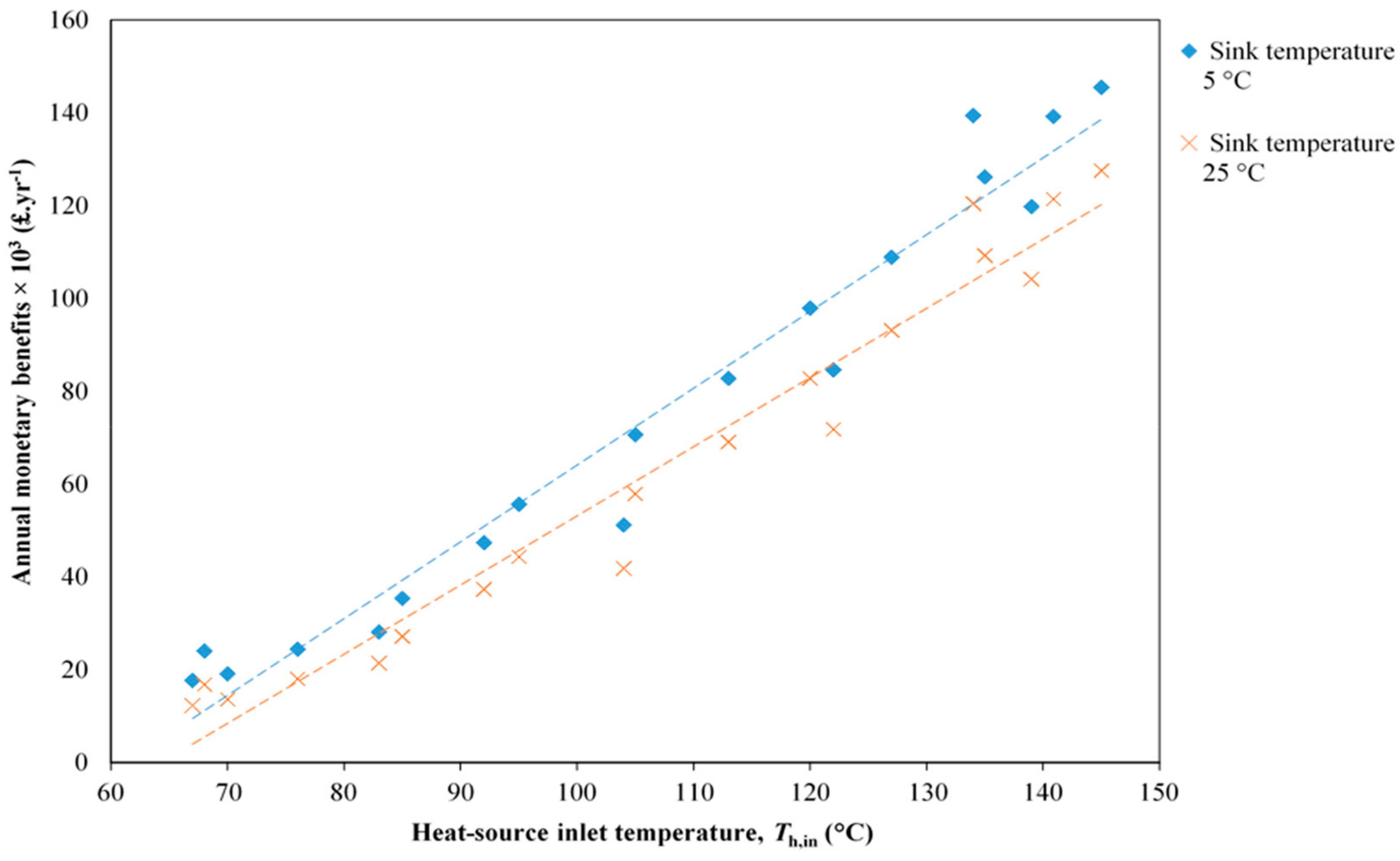
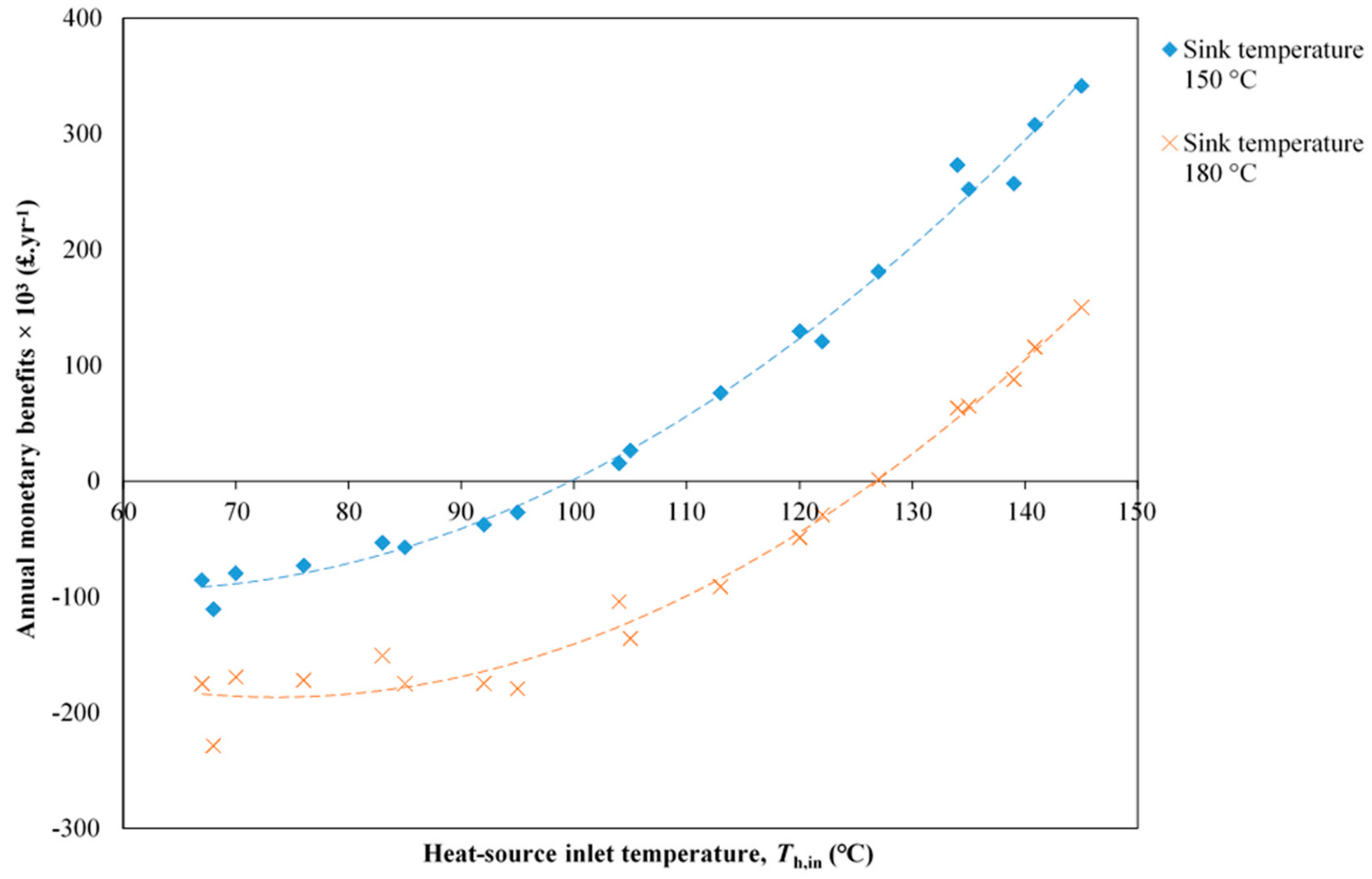
  • The economics of low-grade waste heat recovery are strongly dependent not only on the heat-source temperatures but also on the heat-sink temperatures, with different sensitivities for ORC engines and MVC heat pumps. In the case of China (used as an example), electrical power generation with ORC engines was found to suffer a (small) reduction in monetary benefits amounting to £10,000–£20,000 for the heat sources considered in this work (listed in Table 5) for a 20 °C increase in the sink temperature (representing a change in the ambient temperature, either seasonal or geographical). In the case of MVC heat pumps, an increase of 30 °C in the sink temperature (representing a need or decision to generate medium-temperature stream rather than low-pressure steam) was found to reduce the monetary benefits by a rather larger £100,000–£200,000 for the same heat sources.
  • Electrical power generation with ORC engines showed positive returns when streams with temperatures higher than 70 °C were considered from our list of investigated waste-heat sources, whereas for the generation of steam, economic feasibility is more strongly dependent on gas and electricity prices, as well as the choice of low- vs. medium-pressure steam generation. Returns can become negative more easily than for power generation. Positive annual benefits typically result when streams with temperatures above 100 °C are used for steam generation.
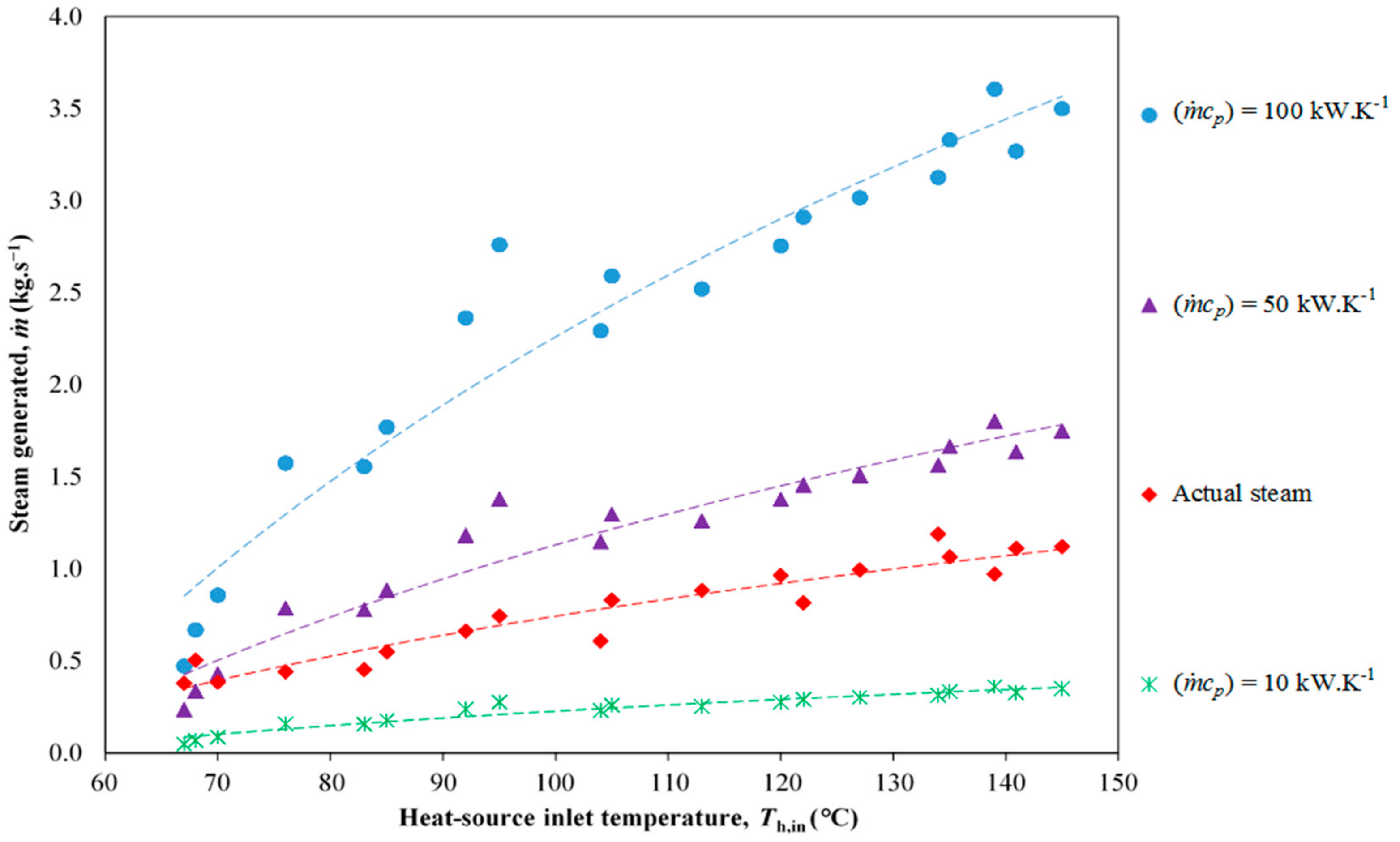
  • In China, low-pressure steam generation with MVC heat pumps showed better annual benefits than power generation with ORC engines for streams with temperatures above ~110 °C and thermal-energy contents above 1.5 MW. For a waste-heat source temperature below ~110 °C or thermal-energy content less than 1.5 MW, ORC engines for electricity generation are monetarily more beneficial than MVC heat pumps for LP steam generation. MVC heat pumps and LP steam generation appear preferable when temperature lifts are less than 40 °C and COPs exceed 4.
  • A similar crossover point, but at a higher heat-source temperature (~135 °C) and a higher thermal content (2.5 MW), exists for India. However, in countries such as Saudi Arabia, the UK and USA, the use of MVC heat pumps was not found to yield financial benefits in our investigated cases.
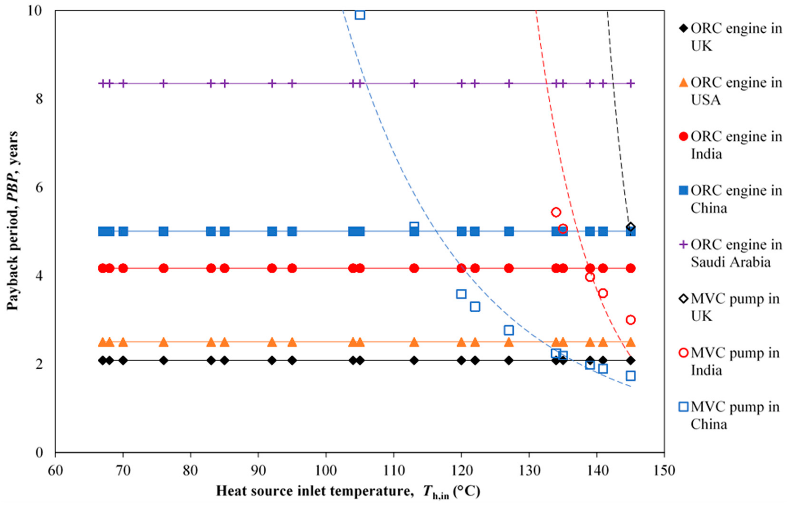
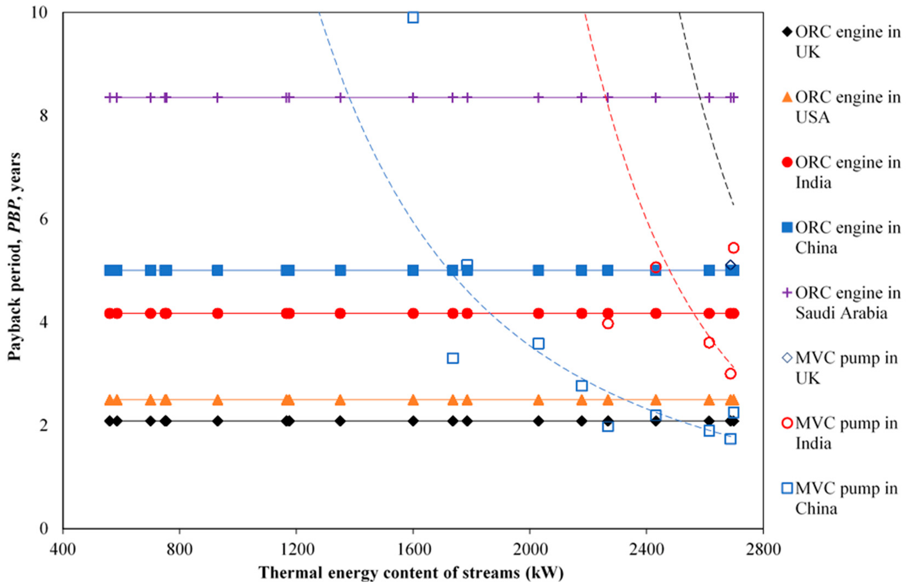
  • Payback periods are in the range of two-to-eight years for electricity generation with ORC engines. In cases where low-pressure steam generation with MVC heat pumps is economically promising, the payback periods are highly influenced by the temperature lift and COP.
  • Given data for one or more waste-heat streams, technoeconomic analyses and comparisons between ORC and MVC heat pump systems may be easily and rapidly performed using the efficiency models proposed in this work, which are sufficiently good representations of commercially available products to warrant their use in such integration studies. For later-stage design, it is necessary to employ more advanced/detailed models, such as in Refs. [85,86,87,88].
The analysis presented here considered heat recovery from individual streams. Opportunities for combined use of multiple streams will be considered in future work.

Author Contributions

Data curation, writing—original draft preparation, N.G.; formal analysis, investigation, software, and validation, N.G. and C.N.M.; conceptualization, funding acquisition, methodology, project administration, resources, supervision, and writing—review and editing, S.M. and C.N.M. All authors have read and agreed to the published version of the manuscript.

Funding

This research was partially funded by Skolkovo Foundation and BP under the UNIHEAT project (M.Sc. bursary to N.G.). This work also was supported by the UK Engineering and Physical Sciences Research Council (EPSRC) [grant numbers EP/P004709/1, EP/R045518/1].

Conflicts of Interest

The authors declare no conflict of interest. The funders had no role in the design of the study; the collection, analyses, or interpretation of data; the writing of the manuscript, or the decision to publish the results.

Nomenclature

ABAnnual monetary benefits, £.yr−1
ACEAnnualized capital expenditure, £.yr−1
AFAnnualization factor
b = T h , out T h , in Ratio of absolute outlet temperature to inlet temperature of waste heat stream
c = T o T h , in Ratio of absolute heat-sink temperature to inlet temperature of waste heat stream
CCCapital cost
CeUnit cost of electricity, £.Wh−1
CgUnit cost of natural gas, £.Wh−1
COPCoefficient of performance
COPMVCCOP of (real) MVC heat pump
COPrCOP of (theoretical) reversible (Carnot) heat pump
COPerCOP of (theoretical) endoreversible heat pump
COPMrCOP of (theoretical) reversible heat pump with source varying temperature
COPMerCOP of (theoretical) endoreversible heat pump with source varying temperature
EECCost of extra electricity consumed, £.yr−1
iInterest rate
m ˙ c p hot , m ˙ c p cold Heat capacity rates of hot and cold streams, W.K−1
MVCMechanical vapour compression
ORCOrganic Rankine cycle
PBPPayback period, years
nNumber of years of operating life of the equipment
Q ˙ hot , Q ˙ cold Thermal energy delivered to or extracted from hot and cold reservoirs/streams, Wth
SAESavings due to avoided purchase of electricity, £.yr−1
SSGSavings due to avoided generated steam, £.yr−1
Th, TcTemperatures of hot and cold reservoirs, K
ToSink temperature, K
Th,in, Tc,inInlet temperatures of hot and cold streams, K
Th,out, Tc,outOutlet temperatures of hot and cold streams, K
TkVariable temperature used in correlations for endoreversible heat pumps, K
W ˙ e Electrical power, We
W ˙ th Thermal power, Wth
Greek
η Thermal efficiency of heat engine
η r Thermal efficiency of (theoretical) reversible (Carnot) engine
η er Thermal efficiency of (theoretical) endoreversible (Novikov) engine
η Mr Thermal efficiency of (theoretical) reversible engine with varying source temperature
η Mer Thermal efficiency of (theoretical) endoreversible engine with varying source temperature
η ORC Thermal efficiency of (real) ORC engine

Appendix A

The following values have been used for calculations unless explicitly specified elsewhere.
Cost of utilities [89,90]:
Table A1. Cost of utilities in various global regions.
Cg, £.kWh−1Ce, £.kWh−1
UK0.0160.14
China0.0220.07
India0.0180.08
Saudi Arabia0.0020.005
USA0.0060.12
Currency conversion factor [91]:
  • 1 GBP = 1.5 USD
Capital costs by system output [2,9,39]:
  • MVC heat pump—200 £.kWth−1
  • ORC—2000 £.kWe−1
Other data:
  • 8000 h per year of operation of the facility.
  • 20 years (n) of operating lifetime of the equipment.
  • Interest rate, i = 5%

References

  1. Energy and Climate Change Committee. Energy and Climate Change—Third Report. UK Oil RefiningReport for UK House of Commons. 2013. Available online: https://publications.parliament.uk/pa/cm201314/cmselect/cmenergy/340/34002.htm (accessed on 3 April 2020).
  2. Element Energy; Ecofys; Imperial College; Stevenson, P.; Hyde, R. The Potential for Recovering and Using Surplus Heat from Industry. Report for UK Department of Energy & Climate Change. (Larksdown Environmental Services); (RHEnergy); 2014. Available online: https://www.gov.uk/government/publications/the-potential-for-recovering-and-using-surplus-heat-from-industry (accessed on 3 April 2020).
  3. McKenna, R.C.; Norman, J.B. Spatial modelling of industrial heat loads and recovery potentials in the UK. Energy Policy 2010, 38, 5878–5891. [Google Scholar] [CrossRef]
  4. Jouhara, H.; Khordehgah, N.; Almahmoud, S.; Delpech, B.; Chauhan, A.; Tassou, S.A. Waste heat recovery technologies and applications. Therm. Sci. Eng. Prog. 2018, 6, 268–289. [Google Scholar] [CrossRef]
  5. Waters, L. Energy Consumption in the UK. Report for Department for Business, Energy & Industrial Strategy; 2019. Available online: www.gov.uk/government/collections/energy-consumption-in-the-uk (accessed on 3 April 2020).
  6. Papapetrou, M.; Kosmadakis, G.; Cipollina, A.; La Commare, U.; Micale, G. Industrial waste heat: Estimation of the technically available resource in the EU per industrial sector, temperature level and country. Appl. Therm. Eng. 2018, 138, 207–216. [Google Scholar] [CrossRef]
  7. CE-HEAT Project. Available online: www.interreg-central.eu/content.node/CE-HEAT.html (accessed on 3 April 2020).
  8. Luo, A.; Fang, H.; Xia, J.; Lin, B.; Jiang, Y. Mapping potentials of low-grade industrial waste heat in Northern China. Resour. Conserv. Recycl. 2017, 125, 335–348. [Google Scholar] [CrossRef]
  9. BCS. Waste Heat Recovery: Technology and Opportunities in U.S. Industry. Report for US Department of Energy; 2008. Available online: www.eere.energy.gov/manufacturing/intensiveprocesses/pdfs/waste_heat_recovery.pdf (accessed on 3 May 2020).
  10. Ebrahimi, K.; Jones, G.F.; Fleischer, A.S. A review of data center cooling technology, operating conditions and the corresponding low-grade waste heat recovery opportunities. Renew. Sustain. Energy Rev. 2014, 31, 622–638. [Google Scholar] [CrossRef]
  11. Olsen, D.; Liem, P.; Abdelouadoud, Y.; Wellig, B. Thermal energy storage integration based on pinch analysis–Methodology and application. Chem. Ing. Tech. 2017, 89, 598–606. [Google Scholar] [CrossRef]
  12. Bagajewicz, M.; Valtinson, G.; Nguyen Thanh, D. Retrofit of crude units preheating trains: Mathematical programming versus pinch technology. Ind. Eng. Chem. Res. 2013, 52, 14913–14926. [Google Scholar] [CrossRef]
  13. Nemet, A.; Jide Isafiade, A.; Klemeš, J.J.; Kravanja, Z. Two-step MILP/MINLP approach for the synthesis of large-scale HENs. Chem. Eng. Sci. 2019, 197, 432–448. [Google Scholar] [CrossRef]
  14. Klemeš, J.J.; Varbanov, P.S.; Walmsley, T.G.; Jia, X. New directions in the implementation of pinch methodology (PM). Renew. Sustain. Energy Rev. 2018, 98, 439–468. [Google Scholar] [CrossRef]
  15. Ferland, K.; Papar, R.; Quinn, J.; Kumar, S. Low Temperature Waste Energy Recovery at Chemical Plants and Refineries. In Proceedings of the 35th Industrial Energy Technology Conference (IETC 2013), New Orleans, LA, USA, 21–24 May 2013; Energy Systems Laboratory, Texas A&M Engineering Experiment Station: College Station, TX, USA, 2013. [Google Scholar]
  16. Hammond, G.P.; Norman, J.B. Heat recovery opportunities in UK industry. Appl. Energy 2014, 116, 387–397. [Google Scholar] [CrossRef] [Green Version]
  17. Sinclair, D.A.J. The Climate Change Levy and Enhanced Capital Allowances–Focus on Waste Heat Recovery Equipment. Master’s Thesis, Heriot-Watt University, Edinburgh, UK, 2001. [Google Scholar]
  18. Brückner, S.; Liu, S.; Miró, L.; Radspieler, M.; Cabeza, L.F.; Lävemann, E. Industrial waste heat recovery technologies: An economic analysis of heat transformation technologies. Appl. Energy 2015, 151, 157–167. [Google Scholar] [CrossRef]
  19. Ammar, Y.; Joyce, S.; Norman, R.; Wang, Y.; Roskilly, A.P. Low grade thermal energy sources and uses from the process industry in the UK. Appl. Energy 2012, 89, 3–20. [Google Scholar] [CrossRef]
  20. Crook, A.W. Profiting from Low-Grade Heat: Thermodynamic Cycles for Low-Temperature Heat Sources; Institute of Electrical Engineers: London, UK, 1994. [Google Scholar]
  21. Little, A.B.; Garimella, S. Comparative assessment of alternative cycles for waste heat recovery and upgrade. Energy 2011, 36, 4492–4504. [Google Scholar] [CrossRef]
  22. Öhman, H.; Lundqvist, P. Comparison and analysis of performance using low temperature power cycles. Appl. Therm. Eng. 2013, 52, 160–169. [Google Scholar] [CrossRef]
  23. Fischer, J. Comparison of trilateral cycles and organic Rankine cycles. Energy 2011, 36, 6208–6219. [Google Scholar] [CrossRef]
  24. Ling-Chin, J.; Bao, H.; Ma, Z.; Taylor, W.; Roskilly, A.P. State-of-the-Art Technologies on Low-Grade Heat Recovery and Utilization in Industry. Intechopen Book, Ch. 4. 2018. Available online: http://0-dx-doi-org.brum.beds.ac.uk/10.5772/intechopen.78701 (accessed on 3 April 2020).
  25. Haddad, C.; Périlhona, C.; Danlosa, A.; François, M.-X.; Descombesa, G. Some efficient solutions to recover low and medium waste heat: Competitiveness of the thermoacoustic technology. Energy Procedia 2014, 50, 1056–1069. [Google Scholar] [CrossRef]
  26. Van de Bor, D.M.; Infante Ferreira, C.A.; Kiss, A.A. Low grade waste heat recovery using heat pumps and power cycles. Energy 2015, 8, 864–873. [Google Scholar] [CrossRef]
  27. Crowe, R. Capturing Waste Heat with Organic Rankine Cycle Systems. Available online: https://www.renewableenergyworld.com/2011/01/24/capturing-waste-heat-with-organic-rankine-cycle-systems/ (accessed on 3 April 2020).
  28. Brasz, J.J. Low Temperature/Small Capacity ORC System Development. In Proceedings of the 1st International Seminar on ORC Power Systems, Delft, The Netherlands, 22–23 September 2011. [Google Scholar]
  29. Law, R.; Harvey, A.; Reay, D. Opportunities for low-grade heat recovery in the UK food processing industry. Appl. Therm. Eng. 2012, 53, 188–196. [Google Scholar] [CrossRef]
  30. Johansson, D.; Rootzén, J.; Berntsson, T.; Johnsson, F. Assessment of strategies for CO2 abatement in the European petroleum refining industry. Energy 2012, 42, 375–386. [Google Scholar] [CrossRef] [Green Version]
  31. BRE; University of Edinburgh; Centre for Sustainable Energy. Research into Barriers to Deployment of District Heating Networks. Report for UK Department of Energy & Climate Change; 2013. Available online: https://assets.publishing.service.gov.uk/government/uploads/system/uploads/attachment_data/file/191542/Barriers_to_deployment_of_district_heating_networks_2204.pdf (accessed on 3 April 2020).
  32. Freeman, J.; Hellgardt, K.; Markides, C.N. An Assessment of solar–thermal collector designs for small-scale combined heating and power applications in the United Kingdom. Heat Transf. Eng. 2015, 36, 1332–1347. [Google Scholar] [CrossRef] [Green Version]
  33. Freeman, J.; Hellgardt, K.; Markides, C.N. An assessment of solar-powered organic Rankine cycle systems for combined heating and power in UK domestic applications. Appl. Energy 2015, 138, 605–620. [Google Scholar] [CrossRef] [Green Version]
  34. Oyewunmi, O.A.; Markides, C.N. Thermo-economic and heat transfer optimization of working-fluid mixtures in a low-temperature organic Rankine cycle system. Energies 2016, 9, 448. [Google Scholar] [CrossRef] [Green Version]
  35. Oyewunmi, O.A.; Taleb, A.I.; Haslam, A.J.; Markides, C. An assessment of working-fluid mixtures using SAFT-VR MIE for use in organic Rankine cycle systems for waste-heat recovery. Comput. Therm. Sci. 2014, 6, 301–316. [Google Scholar] [CrossRef]
  36. Oyewunmi, O.A.; Taleb, A.I.; Haslam, A.J.; Markides, C.N. On the use of SAFT-VR Mie for assessing large-glide fluorocarbon working-fluid mixtures in organic Rankine cycles. Appl. Energy 2016, 163, 263–282. [Google Scholar] [CrossRef] [Green Version]
  37. Cedillos Alvarado, D.; Acha, S.; Shah, N.; Markides, C.N. A technology selection and operation (TSO) optimisation model for distributed energy systems: Mathematical formulation and case study. Appl. Energy 2016, 180, 491–503. [Google Scholar] [CrossRef]
  38. Law, R.; Harvey, A.; Reay, D. Techno-economic comparison of a high temperature heat pump and an organic Rankine cycle machine for low-grade waste heat recovery in UK industry. Int. J. Low-Carbon Technol. 2013, 8, i47–i54. [Google Scholar] [CrossRef]
  39. Arvay, P.; Muller, M.R.; Ramdeen, V.; Cunningham, G. Economic Implementation of the Organic Rankine Cycle in Industry. In Proceedings of the 2011 American Council for an Energy Efficient Economy (ACEEE) Summer Study on Energy Efficiency in Industry, New York, NY, USA, 23–26 July 2011; pp. 1–12. [Google Scholar]
  40. Jung, H.C.; Krumdieck, S.; Vranjes, T. Feasibility assessment of refinery waste heat-to-power conversion using an organic Rankine cycle. Energy Convers. Manag. 2014, 77, 396–407. [Google Scholar] [CrossRef]
  41. Mitsuo, M.B.; Silva, J.A.M.; Oliveira, S.J. Are ORCs a Good Option for Waste Heat Recovery in a Petroleum Refinery? In Proceedings of the 27th International Conference on Efficiency, Cost, Optimization, Simulation and Environmental Impact of Energy Systems (ECOS 2014), Turku, Finland, 15–19 June 2014; Zevenhoven, R., Ed.; Thermal and Flow Engineering Laboratory, Abo Akademi University: Turku, Finland, 2014. [Google Scholar]
  42. Oluleye, G.; Jobson, M.; Smith, R. A hierarchical approach for evaluation of waste heat utilization opportunities. Chem. Eng. Trans. 2014, 39, 1093–1098. [Google Scholar] [CrossRef]
  43. Chen, C.-L.; Li, P.-Y.; Le, S.N.T. Organic Rankine cycle for waste heat recovery in a refinery. Ind. Eng. Chem. Res. 2016, 55, 3262–3275. [Google Scholar] [CrossRef]
  44. Meacher, J. Organic Rankine Cycle Systems for Waste Heat Recovery in Refineries and Chemical Process Plants. In Proceedings of the 3rd Industrial Energy Technology Conference (IETC), Houston, TX, USA, 26–29 April 1981; Energy Systems Laboratory, Texas A&M Engineering Experiment Station: College Station, TX, USA, 1981. [Google Scholar]
  45. Berntsson, T.; Elmeroth, L.P.; Algehed, J.; Hektor, E.; Franck, P.-Å.; Åsblad, A.; Johnsson, F.; Lyngfelt, A.; Gevert, B.; Chalmers EnergiCentrum, Chalmers University of Technology; et al. Towards a Sustainable Oil Refinery. Pre-Study for Larger Co-Operation ProjectsReport for Preem. 2008. Available online: http://publications.lib.chalmers.se/records/fulltext/69752.pdf (accessed on 3 April 2020).
  46. Varga, Z.; Rabi, I.; Farkas, C. Waste heat recovery with organic Rankine cycle in the petroleum industry. Chem. Eng. Trans. 2012, 29, 301–306. [Google Scholar] [CrossRef]
  47. Fuji Oil Company. Low-Temperature Waste Heat Utilize System; Report for Fuji Oil Company; Fuji Oil Company: Tokyo, Japan, 2019. [Google Scholar]
  48. DRD Power. Huntsman UK Trials New Waste-Heat Power System. Available online: http://drdpower.co.uk/huntsman-uk-trials-new-waste-heat-power-system (accessed on 3 April 2020).
  49. Markides, C.N. The role of pumped and waste heat technologies in a high-efficiency sustainable energy future for the UK. Appl. Therm. Eng. 2013, 53, 197–209. [Google Scholar] [CrossRef]
  50. Nag, P.K.; Gupta, A.V.S.S.K.S. Exergy analysis of the Kalina cycle. Appl. Therm. Eng. 1998, 18, 427–439. [Google Scholar] [CrossRef]
  51. Arslan, O. Exergoeconomic evaluation of electricity generation by the medium temperature geothermal resources, using a Kalina cycle: Simav case study. Int. J. Therm. Sci. 2010, 49, 1866–1873. [Google Scholar] [CrossRef]
  52. Ogriseck, S. Integration of Kalina cycle in a combined heat and power plant, a case study. Appl. Therm. Eng. 2009, 29, 2843–2848. [Google Scholar] [CrossRef] [Green Version]
  53. Ahn, Y.; Bae, S.J.; Kim, M.; Cho, S.K.; Baik, S.; Lee, J.I.; Cha, J.E. Review of supercritical CO2 power cycle technology and current status of research and development. Nucl. Eng. Technol. 2015, 47, 647–661. [Google Scholar] [CrossRef] [Green Version]
  54. Li, X.; Tian, H.; Shu, G.; Zhao, M.; Markides, C.N.; Hu, C. Potential of carbon dioxide transcritical power cycle waste-heat recovery systems for heavy-duty truck engines. Appl. Energy 2019, 250, 1581–1599. [Google Scholar] [CrossRef]
  55. Song, J.; Li, X.; Ren, X.; Tian, H.; Shu, G.; Gu, C.; Markides, C.N. Thermodynamic and economic investigations of transcritical CO2-cycle systems with integrated radial-inflow turbine performance predictions. Appl. Therm. Eng. 2020, 165, 114604. [Google Scholar] [CrossRef]
  56. Zamfirescu, C.; Dincer, I. Thermodynamic analysis of a novel ammonia–water trilateral Rankine cycle. Thermochim. Acta 2008, 477, 7–15. [Google Scholar] [CrossRef]
  57. Ajimotokan, H.A.; Sher, I. Thermodynamic performance simulation and design optimisation of trilateral-cycle engines for waste heat recovery-to-power generation. Appl. Energy 2015, 154, 26–34. [Google Scholar] [CrossRef]
  58. Yari, M.; Mehr, A.S.; Zare, V.; Mahmoudi, S.M.S.; Rosen, M.A. Exergoeconomic comparison of TLC (trilateral Rankine cycle), ORC (organic Rankine cycle) and Kalina cycle using a low grade heat source. Energy 2015, 83, 712–722. [Google Scholar] [CrossRef]
  59. Markides, C.N.; Smith, T.C.B. A dynamic model for the efficiency optimization of an oscillatory low grade heat engine. Energy 2011, 36, 6967–6980. [Google Scholar] [CrossRef] [Green Version]
  60. Solanki, R.; Galindo, A.; Markides, C.N. Dynamic modelling of a two-phase thermofluidic oscillator for efficient low grade heat utilization: Effect of fluid inertia. Appl. Energy 2012, 89, 156–163. [Google Scholar] [CrossRef]
  61. Solanki, R.; Mathie, R.; Galindo, A.; Markides, C.N. Modelling of a two-phase thermofluidic oscillator for low-grade heat utilisation: Accounting for irreversible thermal losses. Appl. Energy 2013, 106, 337–354. [Google Scholar] [CrossRef]
  62. Solanki, R.; Galindo, A.; Markides, C.N. The role of heat exchange on the behaviour of an oscillatory two-phase low-grade heat engine. Appl. Therm. Eng. 2013, 53, 177–187. [Google Scholar] [CrossRef]
  63. Kirmse, C.J.W.; Oyewunmi, O.A.; Taleb, A.I.; Haslam, A.J.; Markides, C.N. A two-phase single-reciprocating-piston heat conversion engine: Non-linear dynamic modelling. Appl. Energy 2017, 186, 359–375. [Google Scholar] [CrossRef] [Green Version]
  64. Markides, C.N.; Gupta, A. Experimental investigation of a thermally powered central heating circulator: Pumping characteristics. Appl. Energy 2013, 110, 132–146. [Google Scholar] [CrossRef] [Green Version]
  65. Markides, C.N.; Solanki, R.; Galindo, A. Working fluid selection for a two-phase thermofluidic oscillator: Effect of thermodynamic properties. Appl. Energy 2014, 124, 167–185. [Google Scholar] [CrossRef]
  66. Oyewunmi, O.A.; Kirmse, C.J.W.; Haslam, A.J.; Müller, E.A.; Markides, C.N. Working-fluid selection and performance investigation of a two-phase single-reciprocating-piston heat-conversion engine. Appl. Energy 2017, 186, 376–395. [Google Scholar] [CrossRef] [Green Version]
  67. Palanisamy, K.; Taleb, A.I.; Markides, C.N. Optimizing the non-inertive-feedback thermofluidic engine for the conversion of low-grade heat to pumping work. Heat Transf. Eng. 2015, 36, 1303–1320. [Google Scholar] [CrossRef] [Green Version]
  68. Taleb, A.I.; Timmer, M.A.G.; El-Shazly, M.Y.; Samoilov, A.; Kirillov, V.A.; Markides, C.N. A single-reciprocating-piston two-phase thermofluidic prime-mover. Energy 2016, 104, 250–265. [Google Scholar] [CrossRef] [Green Version]
  69. Kirmse, C.J.W.; Oyewunmi, O.A.; Haslam, A.J.; Markides, C.N. Comparison of a novel organic-fluid thermofluidic heat converter and an organic Rankine cycle heat engine. Energies 2016, 9, 479. [Google Scholar] [CrossRef] [Green Version]
  70. Macwan, S. The Kalina Cycle. A Major Breakthrough in Efficient Heat to Power Generation. In Proceedings of the National Combined Heat & Power and Waste Heat to Power (CHP2013 & WHP2013) Conference and Trade Show, Houston, TX, USA, 7–9 October 2013. [Google Scholar]
  71. Kalina Power. Kalina Cycle. Available online: www.kalinapower.com (accessed on 3 April 2020).
  72. Chen, H.; Yogi Goswami, D.; Stefanakos, E. A review of thermodynamic cycles and working fluids for the conversion of low-grade heat. Renew. Sustain. Energy Rev. 2010, 14, 3059–3067. [Google Scholar] [CrossRef]
  73. Cao, X.-Q.; Yang, W.-W.; Zhou, F.; He, Y.-L. Performance analysis of different high-temperature heat pump systems for low-grade waste heat recovery. Appl. Therm. Eng. 2014, 71, 291–300. [Google Scholar] [CrossRef]
  74. Kiss, A.A.; Landaeta, S.J.F.; Ferreira, C.A.I. Mastering heat pumps selection for energy efficient distillation. Chem. Eng. Trans. 2012, 29, 397–402. [Google Scholar] [CrossRef]
  75. Markides, C.N. Low-concentration solar-power systems based on organic Rankine cycles for distributed-scale applications: Overview and further developments. Front. Energy Res. 2015, 3, 47. [Google Scholar] [CrossRef] [Green Version]
  76. Blanchard, C.H. Coefficient of performance for finite speed heat pump. J. Appl. Phys. 1980, 51, 2471–2472. [Google Scholar] [CrossRef]
  77. Jincan, C. The general performance characteristics of an irreversible absorption heat pump operating between four temperature levels. J. Phys. D: Appl. Phys. 1999, 32, 1428–1433. [Google Scholar] [CrossRef]
  78. Sun, F.; Chen, W.; Chen, L.; Wu, C. Optimal performance of an endoreversible Carnot heat pump. Energy Convers. Manag. 1997, 38, 1439–1443. [Google Scholar] [CrossRef]
  79. Huang, Y.; Sun, D.; Kang, Y. Local stability analysis of a class of endoreversible heat pumps. J. Appl. Phys. 2007, 102, 034905. [Google Scholar] [CrossRef]
  80. Sahin, B.; Kodal, A. Finite time thermoeconomic optimization for endoreversible refrigerators and heat pumps. Energy Convers. Manag. 1999, 40, 951–960. [Google Scholar] [CrossRef]
  81. Oluleye, G.; Jobson, M.; Smith, R.; Perry, S.J. Evaluating the potential of a process site for waste heat recovery. Chem. Eng. Trans. 2014, 39, 1069–1074. [Google Scholar] [CrossRef]
  82. Aneke, M.; Agnew, B.; Underwood, C. Power Generation through the use of Waste Heat Energy from Process Industries: A Greener Approach to Reducing CO2 Emission & Global Warming in Nigeria. In Proceedings of the 2nd FUTO 2011 Alternative and Renewable Energy Conference, Owerri, Nigeria, 16–19 May 2010; Greenfield Education Service: Beijing, China, 2011. [Google Scholar]
  83. Fraser, D.M.; Gillespie, N. The application of pinch technology to retrofit energy integration of an entire oil refinery. Trans. IChemE Part A: Chem. Eng. Res. Des. 1992, 70A, 395–406. [Google Scholar]
  84. Barve, S.; (ThyssenKrupp Industries, Mumbai, Maharashtra, India). Personal communication, 2015.
  85. Schuster, S.; Markides, C.N.; White, A.J. Design and off-design optimisation of an organic Rankine cycle (ORC) system with an integrated radial turbine model. Appl. Therm. Eng. 2020, 174, 115192. [Google Scholar] [CrossRef]
  86. Van Kleef, L.M.T.; Oyewunmi, O.A.; Markides, C.N. Multi-objective thermo-economic optimization of organic Rankine cycle (ORC) power systems in waste-heat recovery applications using computer-aided molecular design techniques. Appl. Energy 2019, 251, 112513. [Google Scholar] [CrossRef]
  87. Chatzopoulou, M.A.; Lecompte, S.; De Paepe, M.; Markides, C.N. Off-design optimisation of organic Rankine cycle (ORC) engines with different heat exchangers and volumetric expanders in waste heat recovery applications. Appl. Energy 2019, 253, 113442. [Google Scholar] [CrossRef]
  88. Pantaleo, A.M.; Simpson, M.; Rotolo, G.; Distaso, E.; Oyewunmi, O.A.; Sapin, P.; De Palma, P.; Markides, C.N. Thermoeconomic optimisation of small-scale organic Rankine cycle systems based on screw vs. piston expander maps in waste heat recovery applications. Energy Convers. Manag. 2019, 200, 112053. [Google Scholar] [CrossRef]
  89. International Gas Union. Wholesale Gas Price Survey. 2016 Edition. Available online: www.igu.org/sites/default/files/node-news_item-field_file/IGU_wholesalegasprice_survey0509_2016.pdf (accessed on 3 April 2020).
  90. Statista Research Department. Electricity Prices by Country in 2015. Available online: www.statista.com/statistics/477995/global-prices-of-electricity-by-select-country (accessed on 3 April 2020).
  91. Exchange Rates UK. Historical Exchange Rates for GBP/USD Currency Conversion in 2015. Available online: www.exchangerates.org.uk (accessed on 3 April 2020).
Figure 1. (a) Schematic of ORC power-cycle system. (b) Pressure–enthalpy diagram for cycle in (a).
Energies 13 02560 g001
Figure 2. (a) Schematic of MVC heat-pump system. (b) Pressure–enthalpy diagram for cycle in (a).
Energies 13 02560 g002
Figure 3. (a) Temperature–entropy diagrams of reversible/Carnot (solid) and endoreversible/Novikov (dashed) heat engine cycles as defined by Equations (2)–(4). (b) Temperature–entropy diagrams of Mr (solid) and Mer (dashed) heat engine cycles as defined by Equations (5)–(7).
Energies 13 02560 g003
Figure 4. Thermal efficiencies of 34 commercial ORC engines from manufacturer datasheets as a function of their corresponding Novikov efficiency. The range of Novikov efficiencies corresponds to heat-source temperatures up to 330 °C (based on a heat-sink temperature of 25 °C).
Energies 13 02560 g004
Figure 5. (a) Temperature–entropy diagrams of reversible (solid) and endoreversible (dashed) heat pump cycles as defined by Equations (10) and (11). (b) Temperature–entropy diagrams of Mr (solid) and Mer (dashed) heat pump cycles as defined by Equations (12)–(19).
Energies 13 02560 g005
Figure 6. COP of 20 commercial MVC heat pumps from manufacturer datasheets as a function of Carnot COP. The range of theoretical Carnot efficiencies corresponds to temperature lifts up to 80 °C (based on a heat-source temperature of 100 °C).
Energies 13 02560 g006
Figure 7. Predictions of ORC engine efficiencies from the empirical model (Equation (8)) and theoretical efficiency models as a function of the heat-source inlet temperature (from 65 to 145 °C), when utilizing the thermal energy from the streams listed in Table 5. The heat sink is assumed to be at 25 °C.
Energies 13 02560 g007
Figure 8. Electrical power generated by ORC engines that utilize the thermal energy available in the streams listed in Table 5 as a function of the heat-source inlet temperature, with the heat sink at 25 °C (“actual power” points and curve). Also shown is the power generated when utilizing streams with the same temperature differences as in Table 5 but with heat capacity rates ( m ˙ c p ) = 10, 50, and 100 kW.K−1.
Energies 13 02560 g008
Figure 9. Predictions of MVC heat pump COPs from the empirical model (Equation (20)) and theoretical COP models as a function of the heat-source inlet temperature (from 65 to 145 °C), when utilizing the thermal energy from the streams listed in Table 5 with the heat sink at 150 °C (low pressure (LP) steam).
Energies 13 02560 g009
Figure 10. LP steam (150 °C) generated by MVC heat pumps when utilizing the thermal energy available in the streams listed in Table 5 as a function of the heat-source inlet temperature (“actual steam” points and curve). Also shown is the LP steam generated when utilizing streams with the same temperature differences as in Table 5 but with heat capacity rates ( m ˙ c p ) = 10, 50, and 100 kW.K−1.
Energies 13 02560 g010
Figure 11. Annual monetary benefits arising from the generation of electricity with ORC engines as a function of the heat-source inlet temperatures which range between 65 and 145 °C when utilizing thermal energy available in the streams in Table 5 with sink temperature at 5 and 25 °C. Based on the electricity price in China (Appendix A), as an example case.
Energies 13 02560 g011
Figure 12. Annual monetary benefits arising from the generation of LP steam (150 °C) and medium pressure (MP) steam (180 °C) with MVC heat pumps as a function of heat-source inlet temperatures which range between 65 and 145 °C when utilizing the thermal energy available in the streams in Table 5. Based on gas/electricity prices in China (Appendix A) as an example case.
Energies 13 02560 g012
Figure 13. Annual monetary benefits resulting from use of ORC engines and MVC heat pumps in various countries as a function of the heat-source inlet temperature when utilizing the thermal energy available in the streams listed in Table 5. The heat sink is at 25 °C for the ORC engines, and 150 °C (LP steam) is produced for the MVC heat pumps.
Energies 13 02560 g013
Figure 14. Annual monetary benefits resulting from use of ORC engines and MVC heat pumps in various countries as a function of the thermal-energy content of the streams when utilizing the thermal energy available in the streams listed in Table 5. The heat sink is at 25 °C for the ORC engines, and 150 °C (LP steam) is produced for the MVC heat pumps.
Energies 13 02560 g014
Figure 15. Payback periods associated with the use of ORC engines and MVC heat pumps in various countries as a function of the heat-source inlet temperature when utilizing the thermal energy available in the streams listed in Table 5. The heat sink is at 25 °C for the ORC engines, and 150 °C (LP steam) is produced for the MVC heat pumps.
Energies 13 02560 g015
Figure 16. Payback periods associated with the use of ORC engines and MVC heat pumps in various countries as a function of the thermal-energy content of the streams when utilizing the thermal energy available in the streams listed in Table 5. The heat sink is at 25 °C for the ORC engines, and 150 °C (LP steam) is produced for the MVC heat pumps.
Energies 13 02560 g016
Table 1. Characterization of the low-grade heat streams in oil refineries [15].
Stream TypePhaseWaste Energy SourcesTemperature (°C)
ProcessLiquidDistillation cuts to be cooled82–104
ProcessGasOverhead condensers65–148
ProcessLiquidRun-down and product streams176–232
ProcessGas and liquidProduct/gas to air coolers112
Table 2. Estimates of surplus heat sources in a refinery [20].
IndustryProcessStream TypeThermal-Energy Content (MW)Temperature (°C)
OilFurnace exhaustGas2080340
OilBoiler exhaustGas615230
OilCondensateLiquid152082
OilProcess waterLiquid92550
OilCondenser cooling waterLiquid231045
Table 3. Estimates of low-grade heat sources in the UK oil refining industry [2].
RefineryRefining Capacity (bbl.day−1)Waste Heat Streams TypeThermal-Energy Content (MW)Temperature (°C)
Essar Stanlow 296,000Liquid205070–90
Gas30150
Esso Fawley270,000Liquid285070–90
Gas425150
Murco Milford Haven #108,000Liquid107070–90
Gas158150
Petroineos Grangemouth200,000Liquid178070–90
Gas264150
Phillips 66 Humber221,000Liquid205070–90
Gas304150
Total Lindsey *207,000Liquid196070–90
Gas292150
Valero Energy Ltd.270,000Liquid187070–90
Gas278150
# The refinery was closed at the end of 2014, then sold to Puma Energy in March 2015, and is now used as a storage terminal. * After February 2015, the capacity of this refinery was halved.
Table 4. Technologies for eat recovery. ORC: organic Rankine cycle; COP: coefficient of performance.
Heat SourcesPreferred Utilization Temperature (°C)Typical Efficiency/COPCapital CostPayback Period (Years)Key ParametersConstraints
Heat exchangersMost heat sources50–300>90%Vary; typical:
£4–200 m−2
<2Amount of heat recoveredTemp. gradients in heat exchanger
Heat upgrade with heat pumpsWaste-water streams, flue gases, distillation cuts being cooled80–1503–5, up to 8 in rare cases£150–200 kW−13–5Inlet/outlet temp. of compressorBoiling point of working fluid
Electricity generation with ORC enginesAir coolers, water coolers, furnace flue gases, gas turbine exhaust, excess low-press. steam100–30010–20%£1000–2000 kW−14–5Working fluid, turbine inlet temp., condenser outlet temp.Boiling point of working fluid
Heat transport for district heatingExcess low-press. steam, unrecycled steam condensate, waste water50–100 (water)
100–150 (steam)
25–75%£900–1000 m−1Depends on energy pricesSupply/return temp.Policies, geographical
Table 5. Process data for low-grade waste-heat streams reported in various literature sources.
Stream No.Th,in (°C)Th,out (°C)Heat Capacity Rate ( m ˙ c p , kW.K−1) Thermal Energy Available Δ H ˙ , , MW) Reference
11136235.01.78 $[81]
21346338.02.70 $
3676080.00.56 $[82]
4685875.00.75 $
5705745.00.58 $
6765128.00.70 $
71055532.0 $1.60[83]
81046026.5 $1.16
91456132.0 $2.68
101406434.0 $2.61
111276133.0 $2.18
12954527.0 $1.35
131355932.0 $2.43
14925028.0 $1.17[84]
15835729.0 $0.75
161395527.0 $2.26
171206235.0 $2.03
181226028.0 $1.74
19855531.0 $0.93
$ These values are not reported in the reference and were evaluated from Q ˙ = Δ H ˙ = ( m ˙ c p ) Δ T .

