Article

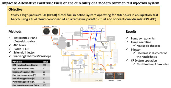
Impact of Alternative Paraffinic Fuels on the Durability of a Modern Common Rail Injection System

1
Escuela de Ingeniería Minera e Industrial de Almadén, Campus de Excelencia Internacional en Energía y Medioambiente, Universidad de Castilla-La Mancha, Plaza Manuel Meca s/n, 13400 Almadén, Spain
2
School of Engineering, University of Birmingham, Edgbaston, Birmingham B15 2TT, UK
3
Escuela de Ingeniería Industrial de Toledo, Campus de Excelencia Internacional en Energía y Medioambiente, Universidad de Castilla-La Mancha, Real Fábrica de Armas. Edif. Sabatini. Av. Carlos III, s/n, 45071 Toledo, Spain
*
Author to whom correspondence should be addressed.
Submission received: 21 July 2020 / Revised: 8 August 2020 / Accepted: 10 August 2020 / Published: 12 August 2020
(This article belongs to the Special Issue New Horizons in Biofuel Production, Technologies, and Emissions)

Abstract

:
Common rail (CR) diesel fuel injection systems are very sensitive to variations in fuel properties, thus the impact of alternative fuels on the durability of the injection system should be investigated when considering the use of alternative fuels. This work studies a high-pressure CR (HPCR) diesel fuel injection system operating for 400 h in an injection test bench, using a fuel blend composed of an alternative paraffinic fuel and conventional diesel (50PF50D). The alternative fuel does not have aromatic components and has lower density than conventional diesel fuel. The injection system durability study was carried out under typical injection pressure and fuel temperature for the fuel pump, the common rail and the injector. The results show that the HPCR fuel injection system and its components (e.g., piston, spring, cylinder, driveshaft and cam) have no indication of damage, wear or change in surface roughness. The absence of internal wear to the components of the injection system is supported by the approximately constant total flow rate that reaches the injector during the whole the 400 h of the experiment. However, the size of the injector nozzle holes was decreased (approximately 12%), being consistent with the increase in the return fuel flow of the injector and rail (approximately 13%) after the completion of the study. Overall, the injection system maintained its operability during the whole duration of the durability study, which encourages the use of paraffinic fuels as an alternative to conventional diesel fuel.

Graphical Abstract

1. Introduction

The technology for the development of fuel injection systems in modern engines has evolved radically in the last two decades to fulfil the increasingly restrictive vehicle emission regulations. The application of the contemporary high-pressure common rail (HPCR) diesel fuel injection systems enable the accurate control of fuel injection as well as the possibility to perform multiple high-pressure fuel injection events. The high-fuel injection pressure leads to a small fuel droplet size, facilitating fuel evaporation and fuel–air mixing for a more homogenous fuel–air mixture. A more homogeneous fuel–air mixture results in a reduction of gaseous carbonaceous emissions (CO and unburnt hydrocarbons (THC)) and especially a significant reduction in particle emissions. However, high injection pressure leads to high fuel temperature [1,2]. Exposure of the fuel through the injector to these operating conditions can affect fuel properties, such as lubricity and density [3,4,5], particularly for low-sulphur diesel fuels [6,7]. Guangxin et al. [3] used a study range for inlet temperatures of 20 °C to 40 °C, similar to that used by Maeda et al. [4] (20 °C to 50 °C). Schaschke et al. [5] used temperatures in the range 25 °C to 100 °C. Then, the deterioration of fuel properties can impact on the components of the HPCR fuel injection system, including the fuel pump and rail [8].
Alternative clean fuels may deal with challenges associated with the depletion of fossil fuel, the carbon footprint of the automotive sector and local pollutant emissions. Biodiesel is the most commonly used alternative fuel for compression ignition engines, producing varying carbon footprint benefits depending on their origin and production process. Promising results from paraffinic fuels with close to zero sulphur and aromatic components are alternatives to traditional diesel fuel in past years [9], including gaseous (CO and THC) and particulate emission benefits [10,11,12]. However, there are discrepancies between the authors regarding NOx emissions, since the increase or decrease in emissions appears to be associated with the operating point, and there is no clear trend [10]. Emission benefits from the combustion of paraffinic fuels are comparable or even better when compared with the emissions obtained from the burning of biodiesel fuels [10,13,14].
The combination of HPCR systems with the use of alternative fuels can accentuate fuel degradation [15] and premature degradation (e.g., corrosion) of some of the fuel injection system components such as the fuel pump [8]. Therefore, it is of crucial importance to understand the compatibility between alternative fuel and most common materials used for the production of the components of the HPCR injection system. For instance, pumps, rail and injectors contain copper, copper alloys and stainless steel [16,17]. Studies mainly focus on biodiesel fuel when investigating the compatibility of the injection system components with alternative fuels. These include the corrosion caused by the use of palm biodiesel on bronze and copper components within the fuel injection systems [18,19], shown to be more significant compared to conventional diesel. Similar results were obtained by Fazal et al. [16] with aluminium. The materials’ compatibility with other biodiesel fuels such as Jatropha curcas, Karanja (Millettia pinnata), Mahua (Mahua longifolia) and Salvadora (Salvadora persica) have also been studied [20]. In addition to the damage to the components of the injection system, some authors have observed biofuel degradation when stored for long periods (e.g., 13 months [21] and 30 months [22]). Paraffinic/diesel fuel blends with low percentages of paraffinic fuel produce comparable fuel injection system deterioration [23,24,25,26] and have similar thermal oxidation stability properties compared to conventional diesel fuel. Therefore, those results position synthetic paraffinic fuels as a suitable clean fuel candidate. However, the impact of paraffinic fuels on the durability of modern injection systems needs to be understood, particularly at proportions more significant than 20% in fuel blends [24].
This research investigates the impact of fuel mixture composed of 50% paraffinic fuel with diesel on the operation and the components of an HPCR injection system. In particular: (a) the wear of the injection pump components; (b) the operating and return flow rates of the injector, pump, and rail; (c) the wear of the injection nozzle; and (d) the ageing of the fuel blend by thermal oxidation stability.

2. Materials and Methods

2.1. Materials

Table 1 includes the properties of the fuel mixture, a 50% fuel blend of paraffinic fuel with conventional ultra-low sulphur diesel (50PF50D). An ASTM D6468 [27] TC40 230V from PM Tamson Instruments measured the oxidation stability of the fuel blend at 150 °C for 180 min, according to ASTM6468 [26,27].
The commercial Bosch HPCR diesel fuel injection system consisted of a three-piston CP1 pump, a common rail and a 6-hole solenoid injector with a diameter of 160 nm and with an angle 144° (according to the manufacturer). The injection pump components analysed were the pistons, springs, cylinders, driveshaft and cam, similarly to a previous work carried out by the authors [28]. Table 2 gives the dimensions of the injection system ducts.
The durability tests were performed using a common rail (CR) pump and the injector test bench STPiW2 from Autoelektronika. A scheme of the experimental flow test bench is shown in Figure 1. A thermocouple (CT), a low-pressure pump (LPP1), and regulated heat exchanger, cooled by a fan, controlled the temperature in the fuel tank, maintained at 50 °C during the tests. A low-pressure pump (LPP2) drove the flow to the heat exchanger, and the electronic control unit governed the cooling system. The tank was waterproof while the pressure gauge (CP3) and the relief valve enabled its utilisation for volatile fuels. The fuel temperature in the tank was 50 °C during the tests. It was decided to use a temperature of 50 °C because the temperatures used to carry out these tests are usually between 30 °C and 60 °C [28,29,30,31,32]. The pressure transducer (CP1) measured the pressure in the high-pressure pump (HPP), and this pressure is controlled by the control unit.
A low-pressure pump (LPP1) drove the fuel from the tank to the HPP, and a pressure transducer (CP2) measured the pressure in the common rail. The opening/closing of the rail control valve (RV) regulated the fuel pressure in the common rail. The fuel pump tester controlled the opening/closing of the PW2 (common rail return), and the injector tester controlled PW1 (flow that reached the injector). The injected and injector return fuels were collected in measuring containers M1 and M2, respectively. Container M3 measured the fuel that came out of the rail return. M1, M2 and M3 have overflows that return the fuel to the tank when filled. The injection control system sets the injection duration and the number of injections per minute.
A special silicone produced the internal moulds of the nozzles to characterise the geometry of the injector holes, as described by Macián et al. 2003 [33]. A Phillips XL30 scanning electron microscope (SEM) produced high-resolution micrographs of the nozzle moulds, coupled with Computer-Aided Design (CAD) software to measure, and calculate characteristic dimensions. This silicone-based method enabled the non-destructive characterisation of inaccessible areas of the injectors. The SEM micrographs characterised the wear and determined the dimensions of the components of the HPCR injection system. The measurements were made before and after the durability tests in two randomly selected sections from 4 of the injector holes.

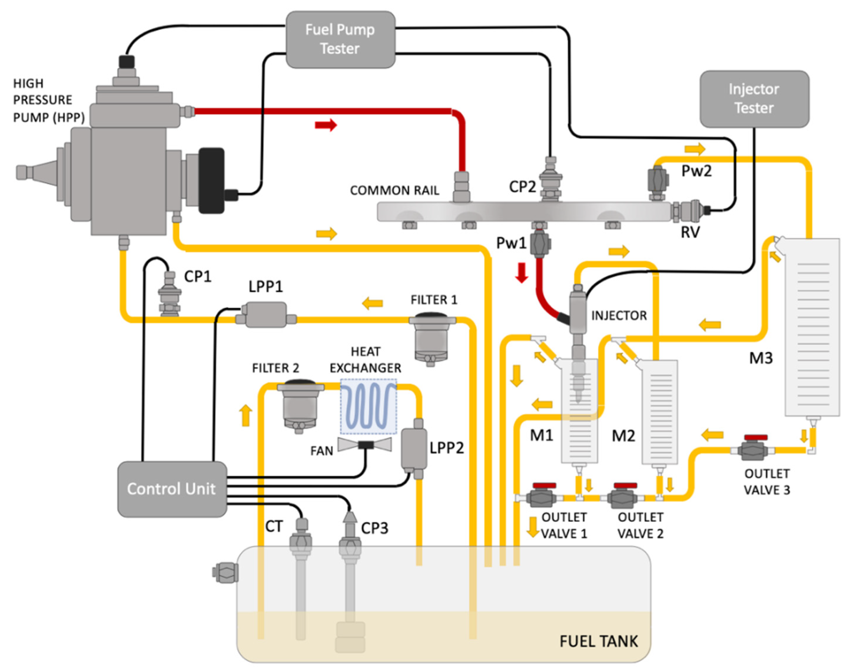
2.2. Development of the Durability Testing Method

The fuel injection operating conditions for the durability experiments aimed to reach the harshest but realistic operation conditions of the equipment. Target conditions included (i) high fuel temperature, (ii) long injection duration, (iii) high injection pressure and (iv) significant fuel flow rates to accelerate the fuel ageing and wear the on the components of the HPCR fuel injection system.
The fuel tank temperature was 50 °C to maintain a significant fuel flow rate through the injector and duration set to 1 ms. This set up was previously reported as representative of realistic conditions and challenging for the durability of the fuel injection system [28]. The nominal maximum rail pressure was 150 MPa; however, it could not be reached for all operating modes. This was probably due to the configuration of the test bench control unit. Therefore, the study of the behaviour of rail pressure and flow rates included a range of flow test bench operating conditions defined by:
(a)
the rotational speed of the high-pressure pump (HPP); and
(b)
the opening/closing percentage of the valves PW1 and PW2 controlling the fuel flow rates to obtain the maximum achievable rail pressure and flow rates.
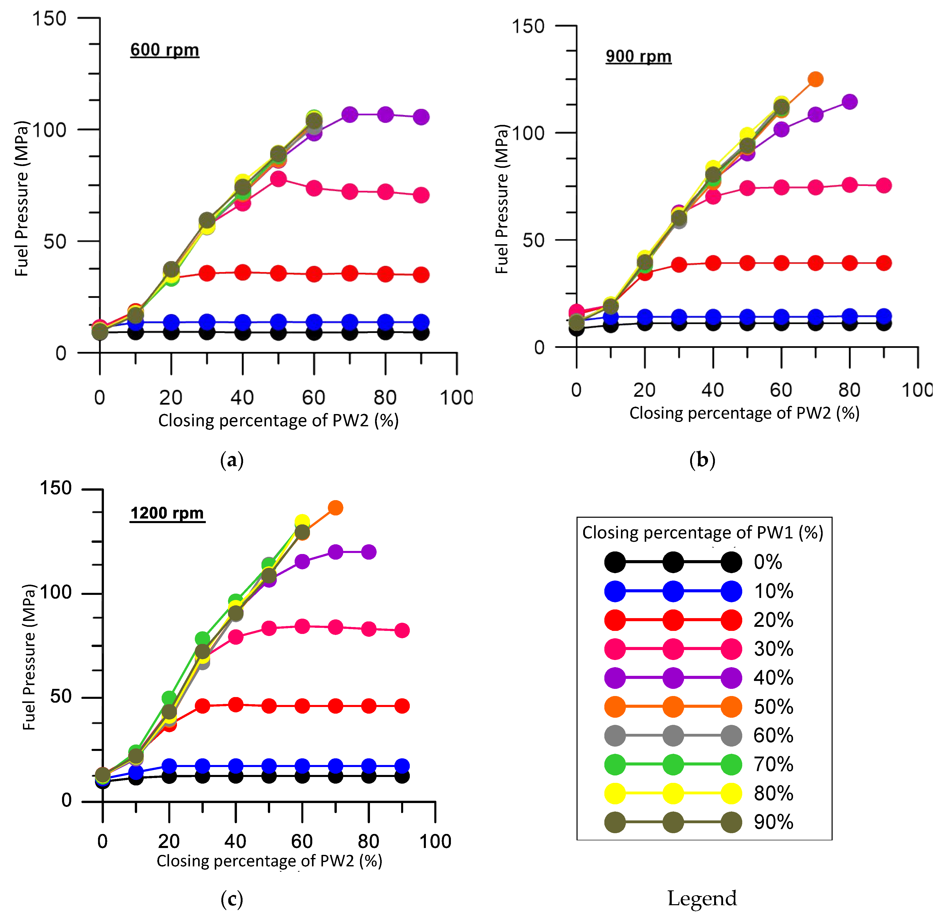
Table 3 lists the ranges of HPP, PW1 and PW2. The range of variation of rotational speed considers the safe operation of the flow test bench when the HPP rotates from 400 to 1200 rpm. The opening/closing percentage of the valve ranges from 0% (fully open) to 90% at increments of 10%, and they were never wholly closed (100%) during the experimental testing for safety reasons. The time taken to fill the calibrated measuring containers M1 (13 cm3), M2 (21 cm3) and M3 (100 cm3) respectively, defines the injector, injector return and rail return flow rates. Figure 2 shows the experimental data after 300 fuel injection events.
The injection control system of the test bench had trouble reaching operation conditions with high closing percentages in PW1 and PW2. As the selected operation condition had to be a stable point, because to carry out the durability test, the operation point used should not produce uncertainties about flows. For this reason, the operation points shown in Figure 2, Figure 3, Figure 4 and Figure 5 were always the ones who provided stabled injection and return flow rates.
Figure 2 shows the maximum value of the fuel injection pressure when the rotational speed of the pump and the closing percentage of the valves PW1 and PW2 are varied. The experimental results show that the highest value of fuel injection pressure in the rail (140 MPa) is when the HPP rotates at 1200 rpm for PW1 and PW2 of 50% and 70%, respectively (please see Figure 2). The injection pressure becomes independent of the pump’s rotational speed at smaller valve closing percentages of PW1 and PW2 (less than 40%). With closing percentages of PW2 over 60%, the fuel injection pressure in the rail remains constant, regardless of the PW1 value.
Since it is necessary to look for the lowest valve closing values that achieve the highest fuel flow rate, with the most elevated possible injection pressure, the following settings are chosen:
(a)
For 600 rpm pump speed, the closing percentage of PW1 is higher than or equal to 40%, and closing percentages of PW2 of 60%;
(b)
For 900 rpm, the PW1 shutdown percentage of 50% with PW2 shutdown percentages of 70%;
(c)
For 1200 rpm, closing rates of PW1 of 50% with closing percentages of PW2 of 70%.
Figure 3 shows the results of the sensitivity analysis for the fuel-injected flow rate as a result of the high-pressure fuel pump rotational speed and the closing percentages of the PW1 and PW2 valves. The increase in PW2 closure generally increases the injected flow rate. However, the injected flow rate is not affected, regardless of the closing percentage of PW2, and the rotational speed of the fuel pump for very low closing percentages of PW1 (0 and 10%). Note that when the closing of PW1 and PW2 is very low (less than 20%), the fuel pressure is low (see Figure 2), and for this reason, no fuel accumulates in the rail. The influence of PW2 is particularly significant at 1200 rpm, reaching a maximum flow injected with 60% PW1 and 60% PW2, corresponding to a fuel pressure of 130 MPa.
Figure 4 shows the effects of the rotational speed of the fuel pump and the closing percentages of PW1 and PW2 valves on the CR return flow rate. The return flow is more significant for PW2 closing percentages below 60% and above 40% of PW1, whereas the return flow increases with the pump rotational speed for all the closing portions of the flow duct control valves.
Figure 5 shows the effect on the injector return flow rate by varying the rotational speed of the fuel pump and the closure percentages of the PW1 and PW2 control valves. The trend is similar to the flow rate injected through the injector (see Figure 3). The injector return flow increases with the pump rotational speed. This return flow is less sensitive to an increase in PW2 value than the actual fuel-injected flow rate. Notably, the injector return flow rate reaches a plateau beyond a PW2 closing value at each PW1. Therefore, in these cases, with the available data, the closing of PW2 does not affect the injector return flow rate.
The operating point for the HPCR injection system durability study was selected as it follows based on the data in Figure 2, Figure 3, Figure 4 and Figure 5:
(a)
The injection pressure ranges from 100 to 120 MPa, these being the highest fuel pressures which provide a large number of combinations for PW1 and PW2;
(b)
The chosen rotational speed is 900 rpm, as the fuel flow rate is not repeatable for higher rotational speeds leading to unstable tests.
To meet the above conditions (a and b) PW1 must be greater than or equal to 50%, and PW2 must be greater than 40% (see Figure 2b). Under these conditions, the points that stand out for a higher injected flow rate are:
(1)
PW1 50% and PW2 70%;
(2)
PW1 60% and PW2 50%;
(3)
PW1 70% and PW2 50%.
From these three points, the first one was selected because it produced a higher fuel return flow rate of the CR and the flow rate was greater than the sum of the flow injected with the return flow of the CR and the injector. Table 4 summarizes the condition used in the durability test. The evolution of the three measurable flows (injected flow, injector return and CR return) were obtained for the duration of the durability test. The test conditions are comparable to those used in previous studies for conventional diesel fuel [28,29,30,31,32,34]. At the end of the durability test, it was verified that the equipment was capable of maintaining the conditions established initially.
As a comparison between the experimental operation conditions with real engine data, Soriano et al. [34] and Fernandez-Yánez et al. [35] used a similar injection system. In these works, the operating mode with the highest load is 90 MPa, with split injections (pre + main injections) of total duration 1080 ms.

3. Results

3.1. Fuel Effect on the Components of the HPCR Fuel Injection System

The fuel injection system was in operation during the whole test duration without providing any indications of failure. After 400 h of testing, a visual inspection of the components of the high-pressure fuel pump suggested no damage in the fuel pump components. For a more detailed analysis, the fuel pump components (piston, spring, cylinder, driveshaft and cam) were scanned using SEM and compared to the micrographs taken before the durability test. Figure 6 shows, as a representative example, the micrographs of one of the head pump piston before (right) and after the experiments (left). The components of the injection system did not show any wear marks, and not was the surface roughness modified, supporting the continuous operation of the fuel pump during the whole duration of the durability study. The findings obtained for this fuel blend are comparable to those obtained using conventional diesel, reporting no damage to the fuel pump and its components (same model as the one used in this work) after durability studies [28,29]. In these works, the evolution of roughness, weight and shape of the components of the pump and the injector nozzle was studied. The durability test, in these cases, was 600 h long using diesel and other fuels (ethanol and biodiesel), finding no significant differences between fuels.
The results also show that the dimensions (diameter) of the injector holes decreased after the durability experiment (Table 5). Figure 7 shows the locations within the injector where the injector nozzle dimensions were measured using the silicone method before (left) and after (right) the 50PF50D durability study. The reductions in nozzle dimensions were 15% for the location close to the injector bag and 10% for the area near the nozzle outlet. Previous studies have reported that the injector holes’ geometry remained constant with diesel fuel [28,29,30,31,32]. In contrast, biodiesel pure with an operational period of only 200 h led to reductions (7%) in the hole size [36]. Furthermore, the original machining marks of the nozzle were also covered as a result of the use of biodiesel [37], just like in this work (see Figure 7). There was also variation in injector hole dimensions, and the topography of the nozzle surface was obtained with biodiesel without changing engine performance, so the 50PF50D fuel blend does not cause any modifications in the operation of the engine either.

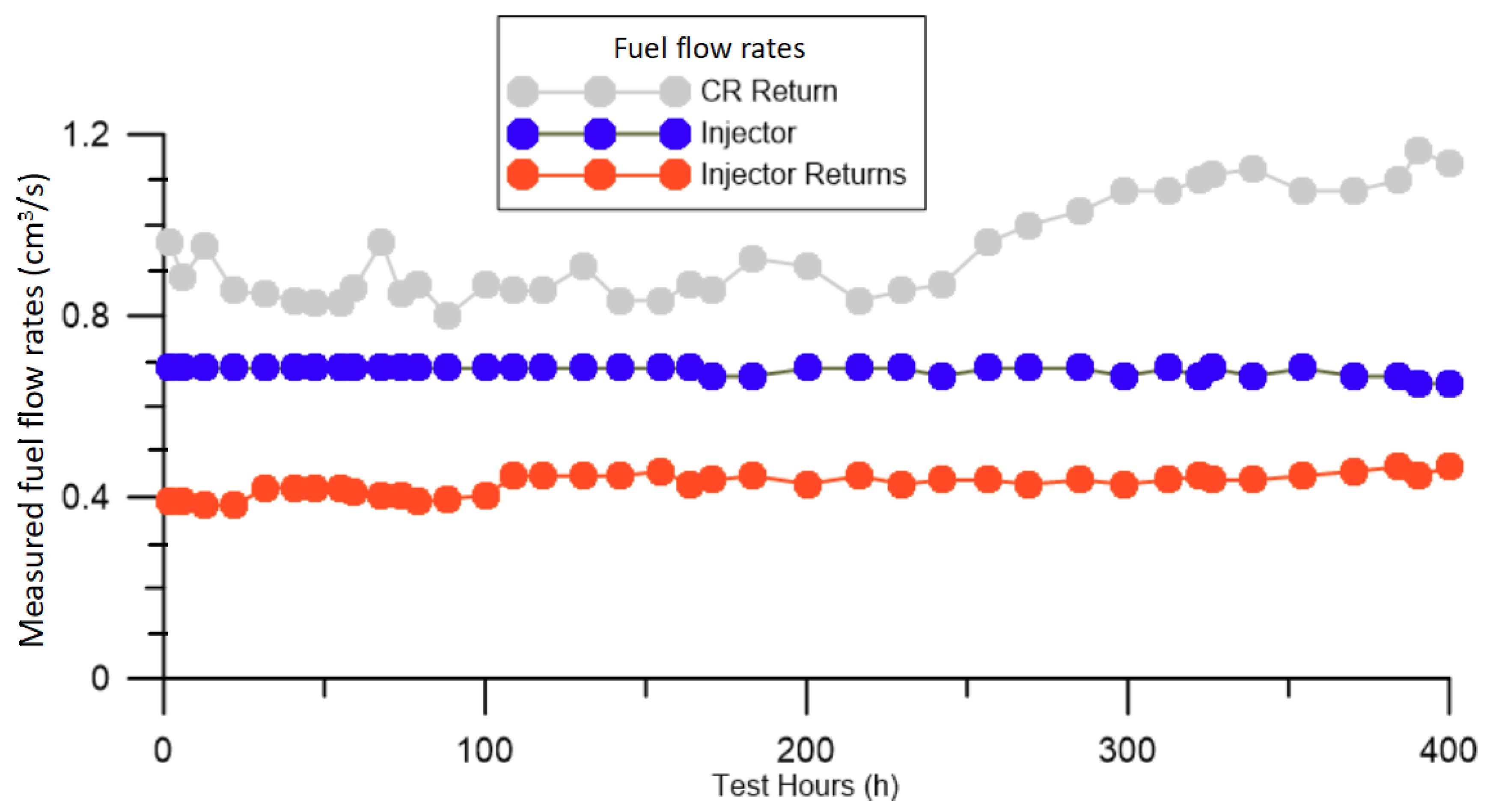
3.2. Fuel Effect on Fuel Flow Rates of the HPCR Fuel Injection System

Figure 8 shows the evolution of the three measured fuel flow rates (injector, injector return and common rail return) during the 400 h of the durability study. The actual injected fuel flow rate (the blue line in Figure 8) is maintained constant during the first 350 h of operation. Then, the injector flow rate slowly decreased by about 5% after the 400 h in comparison to the flow rate at the start of the experiment. On the other hand, the injector return and the CR return flow rates are increased by 15% and 13%, respectively, when compared to the values from the start to the end of the durability test. As the high-pressure pump directs a constant fuel flow rate to the rail, the increase in the CR return flow rate implies that [38]:
(1)
The flow that needs to be accumulated in the rail to reach the set pressure is lower (probably since the operation of the common rail has changed, or that its dimensions have changed); and
(2)
The injector injects less fuel because the holes are smaller and the leftover fuel increased the injector return flow.
The total flow rate input to the injector (actual fuel-injected flow rate + the injector return flow rate) remained approximately constant along with the experiment (less than 4% increase), which supports the absence of internal wear to the components of the HPCR fuel injection system [39]. The small increase (4%) in the total flow through the injector is a result of the variation of cavitation phenomena in the original nozzle, provided by the modification in the shape of the nozzle outlet area that produces a change in the discharge coefficient of the nozzle [40].

3.3. Effect of Durability Experiment on Fuel Stability and Aging

The 50PF50D fuel blend acquired a greenish-brown colour at the end of the 400 h experiment. A similar finding occurred in the experimental evaluation of the corrosivity of diesel fuel with copper conducted by Fazal et al. [16]. With no significant changes in the physical properties, ASTM D6468 governed the 50PF50D fuel blend tests to determine if the paraffinic component of the tested fuel blend had contributed to the evolution of colour. The fuel blend performed well during the ASTM D6468 test, and it did not show any differences in properties or colouring before and after the test. Furthermore, the pure paraffinic fuel presented a reflectance of 91%, similar to the value obtained by Velaers and de Goede [26], and above the 65% suggested by O’Rear et al. [41] as a lower stable reflectance limit. This result indicates that the change of colour could be due to the diesel fraction in the blend. Another study also suggested that the shift in tone in fuel blends with diesel fuel may be due to the diesel fuel itself [42], but further research is required to identify the interactions of the fuel blend with the copper-based components of the injection system.

4. Conclusions

This research investigates the impact of paraffinic fuels, at a 50% fuel blend with diesel, on the durability of the components of a modern HPCR fuel injection system. The described methodology enables the assessment of the impact of fuels on the longevity of modern CR injector components during a controlled accelerated 400 h durability test.
Results have shown that the components of the HPCR fuel injection system did not show any indication of damage, wear or change in the surface roughness that affects their operation after the 400 h durability test. The total flow that reaches the injector was kept approximately stable during the study, supporting the absence of internal wear to the components of the injection system. There was a reduction in the size of the injector holes (approximately 12%), which caused an increase in the injector and CR return flows (almost 13%).
At the end of the 400 h of testing, the 50PF50D fuel had a greenish-brown colour. However, the neat paraffinic fuel exhibited excellent performance in the ASTM D6468 test. Further research is required to understand the interactions of the fuel blend with the copper components of the injection system.

Author Contributions

Conceptualization, all authors; methodology: C.M., J.P. and J.A.S.; performing experiments and investigation: C.M., J.P. and J.M.H.; resources: C.M., A.T., K.D.; supervision: K.D. and A.T.; formal analysis and writing—original draft preparation: C.M. and J.M.H.; writing, review, editing: all authors. All authors have read and agreed to the published version of the manuscript.

Funding

The financial support to Carmen Mata was provided by “Ayudas para estancias en otras universidades y centros de investigación 2011” of Universidad de Castilla-la Mancha.

Acknowledgments

Authors wish to thank the technical support provided by Simón Martínez-Martínez from Facultad de Ingeniería Mecánica y Eléctrica of Universidad Autónoma de Nuevo León in México.

Conflicts of Interest

The authors declare no potential conflicts of interest with respect to the research, authorship, and publication of this article.

References

  1. Herfatmanesh, M.R.; Peng, Z.; Ihracska, A.; Lin, Y.; Lu, L.; Zhang, C. Characteristics of pressure wave in common rail fuel injection system of high-speed direct injection diesel engines. Adv. Mech. Eng. 2016, 8. [Google Scholar] [CrossRef] [Green Version]
  2. Zhang, K.; Huang, X.; Xie, Z.; Zhou, M. Design and optimization of a novel electrically controlled high pressure fuel injection system for heavy fuel aircraft piston engine. Chin. J. Aeronaut. 2018, 31, 1920–1928. [Google Scholar] [CrossRef]
  3. Guangxin, G.; Zhulin, Y.; Apeng, Z.; Shenghua, L.; Yanju, W. Effects of Fuel Temperature on Injection Process and Combustion of Dimethyl Ether Engine. J. Energy Resour. Technol. 2013, 135, 042202. [Google Scholar] [CrossRef] [PubMed]
  4. Maeda, Y.; Murayama, T.; Fukazawa, S. Influence of Fuel Properties on the Injection Characteristics of Fuel Injection Systen in Diesel Engines. Bull. JSME 1975, 18, 411–418. [Google Scholar] [CrossRef]
  5. Schaschke, C.; Fletcher, I.; Glen, N. Density and Viscosity Measurement of Diesel Fuels at Combined High Pressure and Elevated Temperature. Processes 2013, 1, 30–48. [Google Scholar] [CrossRef]
  6. Caprotti, R.; Breakspear, A.; Graupner, O. Diesel injector deposits potential in future fueling systems. In Proceedings of the Powertrain & Fluid Systems Conference and Exhibition, Toronto, ON, Canada, 16–19 October 2006. SAE Technical Paper No: 2006-01-3359. [Google Scholar] [CrossRef]
  7. Barker, J.; Richards, P.; Goodwin, M.; Wooler, J. Influence of High Injection Pressure on Diesel Fuel Stability: A Study of Resultant Deposits. SAE Int. J. Fuels Lubr. 2009, 2, 877–884. [Google Scholar] [CrossRef]
  8. Matzke, M.; Litzow, U.; Jess, A.; Caprotti, R.; Balfour, G. Diesel Lubricity Requirements of Future Fuel Injection Equipment. SAE Int. J. Fuels Lubr. 2009, 2, 273–286. [Google Scholar] [CrossRef]
  9. Gill, S.S.; Tsolakis, A.; Dearn, K.D.; Rodríguez-Fernández, J. Combustion characteristics and emissions of Fischer–Tropsch diesel fuels in IC engines. Prog. Energy Combust. Sci. 2011, 37, 503–523. [Google Scholar] [CrossRef]
  10. Armas, O.; Gómez, A.; Ramos, Á. Comparative study of pollutant emissions from engine starting with animal fat biodiesel and GTL fuels. Fuel 2013, 113, 560–570. [Google Scholar] [CrossRef]
  11. Wu, T.; Huang, Z.; Zhang, W.G.; Fang, J.H.; Yin, Q. Physical and chemical properties of GTL-Diesel fuel blends and their effects on performance and emissions of a multicylinder DI compression ignition engine. Energy Fuels 2007, 21, 1908–1914. [Google Scholar] [CrossRef]
  12. Ezzitouni, S.; Soriano, J.A.; Gómez, A.; Armas, O. Impact of injection strategy and GTL fuels on combustion process and performance under diesel engine start. Fuel 2017, 200, 529–544. [Google Scholar] [CrossRef]
  13. Sajjad, H.; Masjuki, H.H.; Varman, M.; Kalam, M.A.; Arbab, M.I.; Imtenan, S.; Rahman, S.M.A. Engine combustion, performance and emission characteristics of gas to liquid (GTL) fuels and its blends with diesel and bio-diesel. Renew. Sustain. Energy Rev. 2014, 30, 961–986. [Google Scholar] [CrossRef] [Green Version]
  14. Schaberg, P.; Wattrus, M. Comparative Emissions Performance of Blends of GTL Diesel and FAME. In Proceedings of the SAE 2014 International Powertrain, Fuels & Lubricants Meeting, Birmingham, UK, 20–23 October 2014. Paper No: 2014-01-2769. [Google Scholar] [CrossRef]
  15. Christensen, E.; McCormick, R.L.; Sigelko, J.; Johnson, S.; Zickmann, S.; Lopes, S.; Slade, D. Impact of a Diesel High Pressure Common Rail Fuel System and Onboard Vehicle Storage on B20 Biodiesel Blend Stability. SAE Int. J. Fuels Lubr. 2016. [Google Scholar] [CrossRef] [Green Version]
  16. Fazal, M.A.; Haseeb, A.S.M.A.; Masjuki, H.H. Comparative corrosive characteristics of petroleum diesel and palm biodiesel for automotive materials. Fuel Process. Technol. 2010, 91, 1308–1315. [Google Scholar] [CrossRef]
  17. Mallick, P.K. Advanced materials for automotive applications: An overview. Adv. Mater. Automot. Eng. 2012, 5–27. [Google Scholar] [CrossRef]
  18. Sundus, F.; Fazal, M.A.; Masjuki, H.H. Tribology with biodiesel: A study on enhancing biodiesel stability and its fuel properties. Renew. Sustain. Energy Rev. 2017, 70, 399–412. [Google Scholar] [CrossRef]
  19. Haseeb, A.S.M.A.; Masjuki, H.H.; Ann, L.J.; Fazal, M.A. Corrosion characteristics of copper and leaded bronze in palm biodiesel. Fuel Process. Technol. 2010, 91, 329–334. [Google Scholar] [CrossRef]
  20. Kaul, S.; Saxena, R.C.; Kumar, A.; Negi, M.S.; Bhatnagar, A.K.; Goyal, H.B.; Gupta, A.K. Corrosion behavior of biodiesel from seed oils of Indian origin on diesel engine parts. Fuel Process. Technol. 2007, 88, 303–307. [Google Scholar] [CrossRef]
  21. Leung, D.Y.C.; Koo, B.C.P.; Guo, Y. Degradation of biodiesel under different storage conditions. Bioresour. Technol. 2006, 97, 250–256. [Google Scholar] [CrossRef]
  22. Bouaid, A.; Martinez, M.; Aracil, J. Long storage stability of biodiesel from vegetable and used frying oils. Fuel 2007, 86, 2596–2602. [Google Scholar] [CrossRef]
  23. Floweday, G. Potential for Reduced Wear Rates in Diesel Engines Running on Fischer-Tropsch Diesel. In Proceedings of the SAE Technical Papers Powertrains, Fuels and Lubricants Meeting, Florence, Italy, 15–17 June 2009; Volume 15. Paper No: 2009-01–1959. [Google Scholar] [CrossRef]
  24. Swarts, A.; Bell, A.; Mokheseng, K.; Pretorius, M.; Schaberg, P. Comprehensive applications testing of diesel from a commercial scale gas-to-liquids plant. SAE Int. J. Fuels Lubr. 2010, 3, 280–291. [Google Scholar] [CrossRef]
  25. Sajjad, H.; Masjuki, H.H.; Varman, M.; Khan, M.M.R.; Arbab, M.I.; Imtenan, S.; Sanjid, A. Comparative Study of Biodiesel, GTL Fuel and Their Blends in Context of Engine Performance and Exhaust Emission. Procedia Eng. 2014, 90, 466–471. [Google Scholar] [CrossRef] [Green Version]
  26. Velaers, A.J.; de Goede, S. The Properties and Injector Nozzle Fouling Performance of Neat GTL and GTL/EN590 Diesel Blends in Various Diesel Engines. SAE Int. J. Fuels Lubr. 2012, 5. [Google Scholar] [CrossRef]
  27. ASTM D6468-08(2019), Standard Test Method for High Temperature Stability of Middle Distillate Fuels; ASTM International: West Conshohocken, PA, USA, 2019.
  28. Armas, O.; Martínez-Martínez, S.; Mata, C. Effect of an ethanol–biodiesel–diesel blend on a common rail injection system. Fuel Process. Technol. 2011, 92, 2145–2153. [Google Scholar] [CrossRef]
  29. Armas, O.; Mata, C.; Martínez-Martínez, S. Effect of an ethanol–diesel blend on a common-rail injection system. Int. J. Engine Res. 2012, 13, 417–428. [Google Scholar] [CrossRef]
  30. Kegl, B.; Hribernik, A. Experimental analysis of injection characteristics using biodiesel fuel. Energy Fuels 2006, 20, 2239–2248. [Google Scholar] [CrossRef]
  31. Gondal, A.K.; Nautiyal, P.C. Wear investigations of injector nozzle using radionuclide technique. Wear 1991, 147, 375–384. [Google Scholar] [CrossRef]
  32. Lindholm, P.; Björklund, S.; Calvo-Cortes, M. Characterisation of wear on a cam follower system in a diesel engine. Wear 2003, 254, 1199–1207. [Google Scholar] [CrossRef]
  33. Macian, V.; Bermudez, V.; Payri, R.; Gimeno, J. New technique for determination of internal geometry of a diesel nozzle with the use of silicone methodology. Exp. Tech. 2003, 27, 39–43. [Google Scholar] [CrossRef]
  34. Soriano, J.A.; Mata, C.; Armas, O.; Ávila, C. A zero-dimensional model to simulate injection rate from first generation common rail diesel injectors under thermodynamic diagnosis. Energy 2018, 158, 845–858. [Google Scholar] [CrossRef]
  35. Fernández-Yáñez, P.; Armas, O.; Gómez, A.; Gil, A. Developing computational fluid dynamics (CFD) models to evaluate available energy in exhaust systems of diesel light-duty vehicles. Appl. Sci. 2017, 7, 590. [Google Scholar] [CrossRef] [Green Version]
  36. Celik, I.; Sensogut, C.; Aydin, O. Usage of biodiesel as fuel and examining its effects on an engine. Energy Sources Part A Recovery Util. Environ. Eff. 2009, 31, 1857–1865. [Google Scholar] [CrossRef]
  37. Celik, I.; Aydin, O. Effects of B100 Biodiesel on Injector and Pump Piston. Tribol. Trans. 2011, 54, 424–431. [Google Scholar] [CrossRef]
  38. Algayyim, S.J.M.; Wandel, A.P.; Yusaf, D.T. The Impact of Injector Hole Diameter on SprayBehaviour for Butanol-Diesel Blends. Energies 2018, 11, 1298. [Google Scholar] [CrossRef] [Green Version]
  39. Reddy, M.S.; Sharma, N.; Agarwal, A.K. Effect of straight vegetable oil blends and biodiesel blends on wear of mechanical fuel injection equipment of a constant speed diesel engine. Renew. Energy 2016, 99, 1008–1018. [Google Scholar] [CrossRef]
  40. Salvador, F.J.; Gimeno, J.; Carreres, M.; Crialesi-Esposito, M. Fuel temperature influence on the performance of a last generation common-rail diesel ballistic injector. Part I: Experimental mass flow rate measurements and discussion. Energy Convers. Manag. 2016, 114, 364–375. [Google Scholar] [CrossRef] [Green Version]
  41. O’Rear, D.J.; Bacha, J.D.; Tiedemann, A.N. Thermally stable blends of Fischer Tropsch and LCO diesel fuel components. Energy Fuels 2004, 18, 682–684. [Google Scholar] [CrossRef]
  42. Hu, E.; Xu, Y.; Hu, X.; Pan, L.; Jiang, S. Corrosion behaviors of metals in biodiesel from rapeseed oil and methanol. Renew. Energy 2012, 37, 371–378. [Google Scholar] [CrossRef]
Figure 1. A schematic of the flow test bench.
Energies 13 04166 g001
Figure 2. Injection pressure at: (a) 600 rpm HPP rotational speed; (b) 900 rpm HPP rotational speed; and (c) 1200 rpm HPP rotational speed.
Energies 13 04166 g002
Figure 3. Injected flow: (a) 600 rpm HPP rotational speed; (b) 900 rpm HPP rotational speed; and (c) 1200 rpm HPP rotational speed.
Energies 13 04166 g003
Figure 4. Common rail return flow: (a) 600 rpm HPP rotational speed; (b) 900 rpm HPP rotational speed; (c) 1200 rpm HPP rotational speed.
Energies 13 04166 g004
Figure 5. Injector return flow: (a) 600 rpm HPP rotational speed; (b) 900 rpm HPP rotational speed; and (c) 1200 rpm HPP rotational speed.
Energies 13 04166 g005
Figure 6. Surface from the head of the piston 1: (a) before the experiment (0 h); and (b) after the experiment (400 h) using 50PF50D.
Energies 13 04166 g006
Figure 7. Micrographs of the injector holes: (a) nozzle before the experiment (0 h); and (b) nozzle after the experiment (400 h) using 50PF50D.
Energies 13 04166 g007
Figure 8. Evolution of the measured fuel flow rates during the experiment (injected and returns flow rates).
Energies 13 04166 g008
Table 1. Fuel properties.
PropertyDieselParaffinic Fuel
Density at 15 °C (kg/m3)827.1784.6
Viscosity at 40 °C (cSt)2.4673.497
Low heating value (LCV) (MJ/kg)42.743.9
Sulphur (mg/kg)46<10
H/C ratio (molar)1.882.10
Table 2. High-pressure common rail (HPCR) injection system specifications.
DuctDimensions
HPCR-CR duct length from HPCR to CR (mm)540
CR-injector duct length (mm)160
Duct internal diameter (mm)2
Table 3. Test conditions to select the operating point.
ParameterValue
HPP rotational speed (rpm)600, 900 and 1200
PW1 closing (%)From 0 to 90
PW2 closing (%)From 0 to 90
Table 4. Experimental operating conditions of the HPCR fuel injection system.
ParameterValue
HPP rotational speed (rpm)900
Injection duration (ms)1
Injection frequency (Hz)20
Fuel test temperature (°C)50
PW1 closing position (%)50
PW2 closing position (%)70
Fuel injection pressure (MPa)100
Table 5. Dimensions measured from the injector nozzle holes before (0 h) and after (400 h) the experiment using 50PF50D.
Hole Numberd μm (0 h)d μm (400 h)
d1d2d1d2
1148.6157.1125.7140.0
2149.2158.0126.9141.7
3148.3157.5125.9142.7
4147.9158.2126.2141.4
Mean148.5157.7126.2141.5

