Adaptive Overhead Transmission Lines Auto-Reclosing Based on Hilbert–Huang Transform


1
Department of Electrical Engineering, Faculty of Engineering, University of Kurdistan, Sanandaj, Kurdistan 66177-15175, Iran
2
Department of Energy Technology, Aalborg University, 6700 Esbjerg, Denmark
*
Author to whom correspondence should be addressed.
Energies 2020, 13(20), 5416; https://0-doi-org.brum.beds.ac.uk/10.3390/en13205416
Submission received: 3 August 2020
/
Revised: 27 September 2020
/
Accepted: 14 October 2020
/
Published: 16 October 2020
(This article belongs to the Special Issue Protection of Future Electricity Systems)
Abstract
:This paper presents a reliable and fast index to detect the instant of arc extinction for adaptive single-pole automatic reclosing (ASPAR). The proposed method is a simple technique for ASPAR on shunt compensated transmission lines using the Hilbert–Huang Transform (HHT). The HHT method is a combination of the empirical mode decomposition (EMD) and the Hilbert transform (HT). The first intrinsic mode function (IMF1) decomposed by EMD, which contains high frequencies of the faulty phase voltage, was used to calculate the proposed index. HT calculates the first IMF spectrum in the time-frequency domain. The presented index is the sum of all frequency contents below 55 Hz, which remains very low until the fault clearance. The proposed method uses a global threshold level and therefore no adjustment is needed for different transmission systems. This method is effective for various system configurations including different fault locations, line loading, and various shunt reactor configurations, designs, compensation rates, and placement. The performance of the method was verified using 324 test cases simulated in electromagnetic transient program (EMTP) related to a 345 kV transmission line. For all the test cases, the algorithm successfully operated with an average reclosing time delay of 32 ms.
1. Introduction
In recent years, the protection of transmission lines by reclosing switches has become a challenge of improving the reliability of power systems [1]. Approximately 80% of faults in overhead transmission lines are transient (arcing) and single-phase to earth. As a result, there is no need to permanently de-energize the transmission line and send the repair team to patrol for maintenance purposes, then, actually the fault will be cleared by temporary de-energizing of the transmission line and by reclosing the circuit breakers (CBs), the transmission line can restore to its normal operation. In the case of single-phase faults, isolating the faulty phase is enough and there is no need to three phases reclosing [2]. After fault, the arc current will has an extremely large value and its length is constant, and the fault at this stage is called the primary arc. After the faulty phase is isolated from both sides of the line, the arc is still fed through the healthy phases [3]; the fault at this stage is called the secondary arc. Due to the low current of the secondary arc, the ionized column of the arc becomes narrower and moves with the wind, and its length increases until the extinction of it. The time of the secondary arc that occurred is called the dead-time. Dead-time is much less than the reclose time setting in traditional methods, usually between 0.2–0.8 s, hence single-phase reclosure can be done much faster, which has the following benefits for the power system:
- Improving power system marginal stability during faults;
- Improving in transient stability;
- Improving in system reliability and availability;
- Mitigating of switching over-voltages;
- Mitigating of shaft torsional oscillation of large thermal units;
- Minimizing unsuccessful reclosing; and
- Reducing system and equipment shocks.
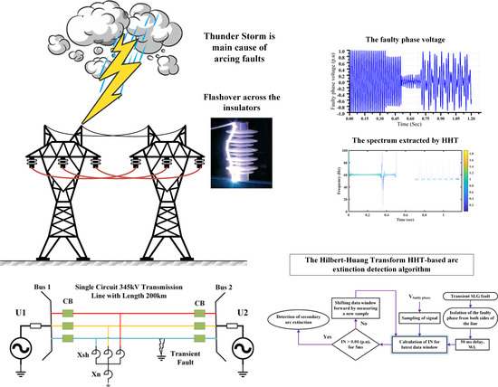
Lightning flashover is the prime cause of transient faults. When lightning strikes the tower body or guard wires, the lightning current passes through the tower body and enters the ground. If the grounding resistance is high, the voltage drop across the tower body will also be large, and eventually a flashover will occur between the tower body and the phase conductor. High tower height, high ground resistance, high pollution severity on insulators, and high average isokeraunic level along the transmission line are all factors that increase the likelihood of transient faults occurring in an overhead transmission line. Obviously, it is possible for lightning to strike the tower, but not cause a fault, but this will weaken the insulation properties of the insulators. In general, the high incidence of thunder storms increases the likelihood of transient faults. In ASPAR studies, modeling starts from the primary arc onward, and previous events have no effect on the results of these studies.
Adaptive single phase auto-reclosing methods must be able to quickly and accurately detect the moment of secondary arc extinction. In this regard, various algorithms have been proposed, a few important groups of them are discussed as follows.
Due to the quasi-square waveform of the arc voltage, the faulty phase voltage contains the odd harmonics of the fundamental component. After the fault clearance, the values of these harmonics decrease and will ideally reach zero. The approaches presented in [4,5,6,7,8,9,10] calculated the harmonic content of the faulty phase voltage or healthy phase currents using various signal processing techniques including time-time (TT) transform, discrete wavelet transform, wavelet packet, and total harmonic distortion (THD). Finally, the fault nature and the moment of extinction of the secondary arc were detected using the calculated criterion values and changings. In the presence of renewable resources, the value of THD is always greater than zero, and this disrupts the performance of such methods.
In [11], the third harmonic of the zero sequence voltage at the local substation was used as a criterion to detect secondary arc extinction. Using voltage measurements at both sides of the line was suggested in [12] by a communication-aided index for ASPAR based on predicted and measured voltage of the faulty phase. The approach proposed in [13] computes the secondary arc current based on measurements to decrease reclosing delay. The proposed real-time method requires signals measured on both sides of the transmission line, however, it can continue to work with local measurements.
In [14], based on local faulty phase voltage and the adaptive cumulative sum method, an increase in voltage amplitude due to fault clearing was recognized. The algorithm [15] utilized the least square method to predict present voltage magnitude value; at the arc extinction moment, the difference between predicted and measured voltage magnitude increased and an adaptive threshold-less approach detected fault extinction. Ghaderi-Baayeh, in [16], introduced a new method for ASPAR based on the second derivative of the faulty phase local voltage angle to determine the secondary arc extinction time in transient fault cases. In [17], the absolute value of the first derivative of the faulted phase local voltage measurement was used to detect the secondary arc extinction. The proposed algorithm has fast performance and uses a low sampling frequency rate and adaptive threshold value. In [18], based on local voltage measurements, a combination of voltage and angle first derivation was utilized to identify fault type and arc extinction detection.
In [19], based on traveling wave theory and using local measured voltage for three types of mixed transmission systems, the occurrence of fault and its location are determined. In the case of fault in the overhead line section, reclosure permission was issued. In [20], for mixed transmission systems, based on wavelet transform and the difference between the currents in the active part of the cable and those in the shields, the overhead section fault was detected. Reclosure into a permanent fault caused damage to the generator shaft of nearby power plants. Since the reclose commands issued for each side of the line were not synchronous, one side of the line always reclosed faster. In [21], a method for selecting the side of the line that should lead reclosing was proposed. In [22], the fault nature, whether permanent or transient, was determined based on the locally measured voltage and using a featured classifier based on support vector machine.
Shunt reactors are widely used in high voltage transmission lines to improve power system stability and line voltage profile regulation [23]. The methods presented in [24,25,26,27,28,29,30] are effective for shunt compensation transmission lines. In these methods, the beat frequency generated after the quenching of the secondary arc was used to detect the quenching of the secondary arc. In [24], the local measured voltage frequency was analyzed using modal transformation and a simple zero crossing algorithm. The secondary arc extinction time was then specified for single- and double-phase-to-ground faults. In [25], mode currents of shunt reactors were calculated, then the presence and number of natural frequencies were used to distinguish the fault nature. In [26], the differences of faulty phase terminal voltage between the two fault states after arc extinction was utilized as a criterion to detect fault nature and clearance. In [27,28], the instantaneous power algorithm was utilized to compute faulty phase reactive and active power, respectively, using local voltage and current measurements. Increasing faulty phase reactive or active power after secondary arc extinction was used to detect arc extinction for shunt compensated transmission lines. In [29], based on the cascaded delayed signal cancellation technique and using the faulted phase local voltage of the shunt compensated line, the average distortion rate was calculated to identify the fault nature and clearance.
The majority of ASPARs presented so far only used the measured data on one side of the transmission line, but references [12,13,30] required measured data on both sides of the transmission line. In [30], the presence of phasor measurement units (PMUs) on both sides of the transmission line was necessary to identify the type of fault and its clearance time.
Long and high voltage transmission lines are very prone to transient faults. On the other hand, to prevent overvoltage, most of these lines are shunt compensated on either side or one side. After the secondary arc extinction, the trapped energy oscillation between the line capacitor and the reactor inductance creates a sub-synchronous component in the isolated phase voltage. In this study, by using the presence of sub-synchronous components in the faulty phase voltage spectrum, an index was proposed to detect fault clearance. During the fault, the voltage of the faulty phase does not contain any sub-synchronous components, however, after extinguishing of the secondary arc, due to the resonance between the shunt reactor and the line capacitor, a sub-synchronous component appears in the voltage. This change in frequency content from 0 to 60 Hz is introduced to detect secondary arc extinction. The Hilbert-Huang Transform (HHT) method is used in this algorithm, which can ideally monitor sub-synchronous components with very low spectrum leakage and high accuracy. Since the proposed method, unlike many previous methods, does not use the THD of measured signals, consequently, it is not sensitive to the presence of renewable resources and is a good option for protecting the grid in the high penetration of renewable resources. System simulation studies show that the proposed algorithm estimates the fault clearing instant accurately for auto-reclosing.
2. Modeling of Understudy System
Figure 1 shows the understudy 345 kV transmission line with the length of 200 km. The network had two buses that were connected to the power grid via two Thevenin equivalent voltage sources. The short circuit levels of the U1 and U2 equivalents were 10 GVA and 15 GVA, respectively. Additionally, the x/r ratio of the positive and zero sequences was 10 and 4, respectively. Table 1 shows the parameters of the single circuit transmission line for the positive and zero sequences. This transmission line was transposed and modeled as the frequency-dependent line in the EMTP software environment. The shunt reactor, as shown in Figure 1, had four windings and was grounded through an inductance to mitigate secondary arc current. The shunt reactor parameter calculations are expressed as follows for different cases.
Secondary Modeling
In this paper, the Kizilcay method for secondary arc modeling in EMTP software was used. More details can be found in [31], which are not repeated here for brevity. The specifications of the arc used in the simulations were as follows:
- Initial resistance (r0): 150 mΩ
- Voltage per unit of length (u0): 1.1 V/cm
- Initial time constant (τ0): 960 ms
- Initial length (l0) of arc: 3.5 m
3. Hilbert–Huang Transform
An analytic signal is a complex-valued function without any negative frequency components. The real and imaginary parts of an analytic signal are real-valued functions related to each other by the Hilbert transform (HT). The HT of the real function is equal to . The definition of HT is as follows:
where the symbol ‘*’ denotes the convolution operation and P indicates the Cauchy principal value. The analytic function of with respect to time can be defined as follows:
where and is the analytic function calculated for the real function . m and φ are the instantaneous energy and phase functions in terms of time, respectively. It is unnecessary to compute the integral in (1) to achieve the HT of . Instead, in the first step, the Fourier transform of the real function is calculated, then its negative frequency components are set to zero and the inverse Fourier transform applied to it. The obtained function is the analytic function calculated for the real function , which its imaginary part is . The instantaneous frequency of the real function is:
The method of calculating the frequency-time distribution for the square amplitude of can be explained using HT. HT is a very suitable method for single mode signals and also calculates the energy distribution in time and frequency. However, the majority of signals are multi-components and their frequency content is spread in the frequency domain. In HHT method, to solve this problem, the input signal was first divided into several intrinsic mode functions (IMFs) by the empirical mode decomposition (EMD) method, where IMFs are time-varying mono-component (single frequency) functions [32]. Then, each of these IMFs is transformed by HT to the frequency domain and their energy is expressed in terms of time and frequency. Using the sifting process, the input signal is decomposed in terms of IMFs [32]:
where R(t) is the residual function and n is the number of IMFs. IMFi is the ith decomposed IMF. The analytic functions of IMFs are calculated using the method described above. Each of these functions represents part of the original signal spectrum. and vectors are calculated for each in the time domain. Finally, the 2n vector, with the same length as the time vector t, are the output of the HHT. The spectrum of the input signal is the combination of these vectors:
where and are the instantaneous energy and frequency functions in terms of time for , respectively. Moreover, sparse matrix is a matrix that has a large number of zeros. function generates a sparse matrix from the triplets t, , and such that . Entries that have no value assigned to them are equal to zero. The lengths of the three vectors t, , and are equal.
4. Proposed Method
Many high voltage transmission lines have shunt compensation, which is placed on either side of the transmission line or one side only. Reactors are usually grounded by inductance to reduce the flow of secondary arc current, and after the fault clearance, the shunt reactor and capacitor of the transmission line are parallel to each other. The energy trapped in the reactor and shunt capacitor of the transmission line oscillates until complete damping, and this energy oscillation between the transmission line and the parallel compensation creates a sub-synchronous component in the isolated phase voltage. In the literature, the created resonance after fault clearance has been used to diagnose secondary arc extinction [15,18,24,25,26,27,28,29]. There is no sub-frequency component during fault, however, after the secondary arc extinguishing in the frequency range of 0 to 60 Hz, a sub-synchronous component appears in the faulty phase voltage for compensated transmission lines. Therefore, in this paper, the energy in the bandwidth of 0 to 55 Hz of the faulty phase voltage was used as a criterion for detecting secondary arc extinction. The frequency of these sub-synchronous components is practically between 30 Hz and 45 Hz for 60 Hz power systems [33].
Due to the limitations on the computational burden, a small data window should be used in protection system, and on the other hand, there is an edge effect in all signal processing methods, hence, both of these constraints should always be considered in choosing the length of the data window. The following index is proposed as a criterion for detecting secondary arc extinction:
where IN represents the sum of the energy of all sub-synchronous components in the faulty phase voltage. U is the last measured window of the faulty phase voltage with the length of WL. is the first decomposed IMF of U. is the output of the Hilbert transformation of , where the central sample of the data window was used here to calculate IN for avoiding the edge effect. HHT can extract sub-synchronous components without being affected by the fundamental 60 Hz component.
Figure 2a shows the faulty phase voltage at Bus 1 for the single line to ground transient fault at 30% of the line. The reactance of the effectively grounded shunt compensator at Bus 2 was 1506.60 Ω. The fault occurred at 350 ms and after 150 ms, the faulty phase was completely isolated from both sides. From 350 to 500 ms, the transient fault had an extremely large current without any differences in its characteristics from the permanent fault. Transient fault at this stage is called the primary arc and its length is almost constant. From the moment of 0.5 s onward, the arc length increased slowly until the transient fault was cleared. The simulation was performed for 1.2 s. Figure 2b shows the spectrum extracted by HHT. The HHT method has a small leakage spectrum and the different components have little effect on each other. Figure 2c illustrates the proposed index for a 1920 Hz sampling frequency (32 samples per 60 Hz cycle) and WL = 50 ms, where the value is zero during the secondary arc and increases after the secondary arc is extinguished.
Figure 3 shows the first three extracted IMFs from the voltage waveform in Figure 2a. The voltage waveform was decomposed to 10 IMFs, but high-order IMFs had very little energy and are not shown here. In the EMD method, always contains high-frequency contents of the input signal. As shown in Figure 3a,b, the sub-synchronous component only appeared in the of the frequency spectrum. Thereby, is the most suitable IMF to monitor the sub-synchronous component due to secondary arc extinction.
Figure 4 shows the flowchart of the proposed algorithm. The proposed method detects fault clearance for shunt compensated transmission lines, and recognition of permanent or transient faults was not within the scope of this paper, and the fault type was assumed to be a transient single line to ground (SLG) fault. After the single-pole operation of the CBs on both sides of the transmission line, the faulty phase was isolated. It was assumed that the distance protections on both sides of the transmission line quickly de-energized the faulty phase. Some papers have assumed that the fault was transient and waited for the secondary arc extinction. In this case, if the secondary arc is not detected after a certain time (about 1.5 to 3 s), it is concluded that the fault is not transient and the initial assumption is wrong, and the three-phase trip command is issued. In this case, the secondary arc extinction detection algorithm is used to detect the nature of the fault. The problem with this fault nature recognition is the delay of about 1.5 to 3 s, which means that the system has been in two phases for this period in the presence of a permanent fault for no reason, and this causes the power system to move more toward instability. In another category of papers, a separate method was proposed to identify the nature of the fault, which did this much faster than the first case. These methods usually use the presence of odd harmonics during the secondary arc or the presence of high frequency components during the primary arc at voltage. In any case, the detection of fault instant, fault location, and fault nature was not in the scope of this paper and the contribution of this paper is in the detection of secondary arc extinction.
The algorithm was delayed 50 ms, thus all samples in the data window were measured after faulty phase isolation, next, the algorithm began to calculate IN using the faulty phase voltage. In the simulations performed in this paper, IN, during the secondary arc, was in most cases zero and sometimes takes very small values. However, after the secondary arc extinction, its value increases and must be greater than the threshold value of 0.01 p.u. for 5 ms to confirm fault clearance. The counting strategy is used in digital protection to improve the reliability of the relay operation or avoid relay maloperation. Checking a protection decision for several times improves the probability of successful operation.
Due to the presence of noise in real signals and to prevent protecting system mal-operation, IN was not compared with zero or smaller threshold value, however, the proposed criterion did not need any pre-calculation of the threshold value and the threshold value had a global feature. After each comparison of IN with the threshold level, the data window shifted forward and the new IN value was calculated. After secondary arc extinction and deionization of the arc path, the reclose command was issued for the local CB.
The main contributions of this paper include the following:
- Extraction and monitoring of sub-synchronous voltage component using HHT, which is a powerful and suitable tool for this application.
- Proposing a criterion that is zero in most moments and cases during the secondary arc and takes a large amount immediately after the secondary arc is extinguished.
- The proposed criterion is very insensitive to voltage magnitude oscillations during the secondary arc, unlike many existing methods.
5. Simulations and Results
To verify and validate the effectiveness and accuracy of the proposed method for ASPAR, various simulation tests were carried out under different fault locations, line loadings, and various shunt reactor configurations, designs, compensation rates, and placements. The EMTP software was utilized with a 50 ms data window length (WL) and 1.92 kHz sampling frequency rate (32 samples per cycle for 60 Hz).
The reactors used in the simulations of this paper were grounded efficiently or to reduce the secondary arc current, and the three-phase shunt reactors were grounded through a reactance Xn. In the literature, two methods for calculating Xn have been proposed [34,35,36]. The method presented in [34,35] is independent of the transmission line length, but reduced the fault current less than the method presented in [36]. The reactance value calculated according to the method in [34,35] was always less than the [35] method. The following is the calculation of Xn based on these two methods.
where , , F, Xsh, and Xn are positive sequence line susceptance, zero sequence line susceptance, shunt compensation rate, the equivalent reactance of line shunt reactor, and equivalent reactance of neutral reactor, respectively. The reactances calculated in (9) and (10) corresponded to the placement of the reactor only on one side of the line. If the transmission line is compensated from both sides, the reactance value of each reactor on each side of the line was twice of the Xsh and Xn reactances calculated above. In other words, the reactive power consumption of the equivalent reactor was divided into two. Table 2 shows the number of shunt reactors for the placement of one or both sides of the line, three rates of compensation 0.5, 0.75, and 0.95, and three modes of effective grounding and grounding based on the methods in [34,35,36].
Table 3 shows the performance of the proposed technique for different power system conditions and types of shunt compensation. Fault clearing detection delay (FCDD) is defined as the time difference between the secondary arc extinction detection and the secondary arc extinction moment obtained from the simulation. Simulations were performed for medium and high loading of the transmission line and various fault locations. By measuring the faulty phase voltage on both sides of the transmission line, the algorithm was tested for both substations adjacent to the line. As can be seen, regardless of the power system conditions and the type and rate of compensation, the proposed scheme can accurately and quickly detect fault clearance. The average FCDD for 324 tested cases was 32 ms.
Figure 5a shows the faulty phase voltage at Bus 2 for the single line to ground fault at 30% of the line. The Xsh and Xn of the inductively grounded shunt compensators at each side of the lines were 2380.60 and 461.42 Ω, respectively. Fundamental voltage magnitude fluctuations cause energy spreadation in low frequency components on the most signal processing methods. The HHT method adaptively distinguishes between fundamental voltage magnitude fluctuations and the presence of a low frequency component, therefore the spectrum extracted from the sub-synchronous components receives the least effect from the fundamental component. During the secondary arc, due to the reduction of the fault current, the length of the arc fluctuates more, and as a result, the voltage of the faulty phase fluctuates severely (Figure 5a). As demonstrated in Figure 5b, the proposed criterion is independent of the arc behavior and the IN value is zero during the secondary arc. This is due to the use of and the excellent ability of HHT to decompose signal components with minimal spectrum leakage. Similar waveforms of field measurements, obtained from electrical systems reported in [37], showed similar voltage behavior, hence, it is important that the secondary arc extinction detection method is independent of the voltage behavior during the dead-time.
Due to the growth of renewable resource penetrations in the power system, the need for adaptive protection methods is increasing. Renewable resources are generally connected to the power system through power electronic interfaces, and one of their destructive effects is increasing the power system THD [38]. Many of the methods proposed in the literature are based on the increase of THD during the secondary arc and the sharp decrease after the fault clearance. In the presence of renewable resources, many of these methods lose their ability to function properly due to the lack of THD reduction after fault clearance [4,5,6,7,8,9,10]. The proposed method does not use the harmonics in voltage to calculate the criterion, and in addition, due to the high capability of the HHT method, the proposed method can have a correct and fast performance regardless of the high penetration of renewable resources in the power system and THD value.
In Table 4, a group of recent papers have been selected for qualitative comparison with the presented method. As can be seen, the strengths of the proposed method include the following:
- Low starting time delay;
- Fast reclosing time delay (with average 32 ms);
- Medium sampling frequency (1.920 kHz);
- Very low sensitivity to voltage magnitude oscillation; and
- Global threshold.
6. Conclusions
In this paper, a novel algorithm for detecting secondary arc extinction in shunt compensated transmission lines was presented. Using the Hilbert–Huang transform (HHT), the absolute value of all frequency contents below 60 Hz of the fault phase was calculated. Secondary arc extinction was then detected using a global threshold value. The algorithm was tested on a transmission line for different fault location, line loading, and various shunt reactor configurations, designs, compensation rates, and placement. The test results validate the algorithm’s performance as well as its independence of the shunt compensation configuration. The main features of the algorithm can be summarized as follows:
- No adjustment is needed for different transmission systems, threshold is global.
- Fast operation time.
- Non-communication based (i.e., use of local measurements).
- Independent from voltage magnitude variation during dead-time.
- Using voltage phasor where it is more reliable rather than the current.
- Fast operation time; average reclosing time delay is 32 ms.
- Applicable for high penetration of renewable resources in the power system.
- Applicable for all types of shunt reactor configurations.
- Algorithm starting time delay is 50 ms, as a result, the algorithm can work properly. even when the fault clears very fast.
- Using the HHT, which is very powerful and practical in the analysis of nonstationary and nonlinear signals.
Author Contributions
Methodology, validation, writing—original draft preparation, A.G.B.; Review and editing, supervision, N.B. All authors have read and agreed to the published version of the manuscript.
Funding
This research received no external funding.
Conflicts of Interest
The authors declare no conflict of interest.
References
- Bayati, N.; Hajizadeh, A.; Soltani, M. Protection in DC microgrids: A comparative review. IET Smart Grid 2018, 1, 66–75. [Google Scholar] [CrossRef]
- Bayati, N.; Baghaee, H.R.; Hajizadeh, A.; Soltani, M. A Fuse Saving Scheme for DC Microgrids with High Penetration of Renewable Energy Resources. IEEE Access 2020, 8, 137407–137417. [Google Scholar] [CrossRef]
- Bayati, N.; Baghaee, H.R.; Hajizadeh, A.; Soltani, M. Localized protection of radial DC microgrids with high penetration of constant power loads. IEEE Syst. J. 2020. [Google Scholar] [CrossRef]
- Nikoofekr, I.; Sadeh, J. Determining secondary arc extinction time for single-pole auto-reclosing based on harmonic signatures. Electr. Power Syst. Res. 2018, 163, 211–225. [Google Scholar] [CrossRef]
- Dias, O.; Tavares, M.C.; Magrin, F. Hardware implementation and performance evaluation of the fast adaptive single-phase auto reclosing algorithm. Electr. Power Syst. Res. 2019, 168, 169–183. [Google Scholar] [CrossRef]
- Jamali, S.; Ghaffarzadeh, N. Adaptive single-pole auto-reclosure for transmission lines using sound phases currents and wavelet packet transform. Electr. Power Compon. Syst. 2010, 38, 1558–1576. [Google Scholar] [CrossRef]
- Jannati, M.; Moshtagh, J. Hardware implementation of a real-time adaptive single-phase auto-reclosure for power transmission lines. Int. Trans. Electr. Energy Syst. 2020, 30, e12344. [Google Scholar] [CrossRef]
- Jamali, S.; Ghaffarzadeh, N. Adaptive single pole auto-reclosing using discrete wavelet transform. Eur. Trans. Electr. Power 2011, 21, 973–986. [Google Scholar] [CrossRef]
- Luo, X.; Huang, C.; Jiang, Y.; Guo, S. An adaptive three-phase reclosure scheme for shunt reactor-compensated transmission lines based on the change of current spectrum. Electr. Power Syst. Res. 2018, 158, 184–194. [Google Scholar] [CrossRef]
- Jannati, M.; Nazari, M.Y. Improving the stability of power transmission lines based on an adaptive single pole auto-reclosure using a two-step strategy. IET Gener. Transm. Distrib. 2020, 14, 873–882. [Google Scholar] [CrossRef]
- Jamali, S.; Parham, A. New approach to adaptive single pole auto-reclosing of power transmission lines. IET Gener. Transm. Distrib. 2010, 4, 115–122. [Google Scholar] [CrossRef]
- Zadeh, M.D.; Rubeena, R. Communication-aided high-speed adaptive single-phase reclosing. IEEE Trans. Power Deliv. 2012, 28, 499–506. [Google Scholar] [CrossRef]
- Vogelsang, J.; Romeis, C.; Jaeger, J. Real-time adaption of dead time for single-phase autoreclosing. IEEE Trans. Power Deliv. 2015, 31, 1882–1890. [Google Scholar] [CrossRef]
- Khodadadi, M.; Noori, M.R.; Shahrtash, S.M. A noncommunication adaptive single-pole autoreclosure scheme based on the ACUSUM algorithm. IEEE Trans. Power Deliv. 2013, 28, 2526–2533. [Google Scholar] [CrossRef]
- Jamali, S.; Baayeh, A.G. Detection of secondary arc extinction for adaptive single phase auto-reclosing based on local voltage behaviour. IET Gener. Transm. Distrib. 2017, 11, 952–958. [Google Scholar] [CrossRef]
- Baayeh, A.G.; Jamali, S. Detection of Secondary Arc Extinction for Adaptive Single Phase Auto-Reclosing. In Proceedings of the 11th International Conference on Protection and Automation in Power System IPAPC, Tehran, Iran, 17–18 January 2017. [Google Scholar]
- Baayeh, A.G.; Jamali, S. Adaptive Single Phase Auto-Reclosing Using Voltage Magnitude Pattern. In Proceedings of the 31th International Power System Conference, Tehran, Iran, 24–26 October 2016. [Google Scholar]
- Zhalefar, F.; Zadeh, M.R.; Sidhu, T.S. A high-speed adaptive single-phase reclosing technique based on local voltage phasors. IEEE Trans. Power Deliv. 2015, 32, 1203–1211. [Google Scholar] [CrossRef]
- Sohn, S.H.; Cho, G.J.; Kim, C.H. A Study on Application of Recloser Operation Algorithm for Mixed Transmission System Based on Travelling Wave Method. Energies 2020, 13, 2610. [Google Scholar] [CrossRef]
- Granizo Arrabe, R.; Platero Gaona, C.A.; Alvarez Gomez, F.; Rebollo Lopez, E. Novel Auto-Reclosing Blocking Method for Combined Overhead-Cable Lines in Power Networks. Energies 2016, 9, 964. [Google Scholar] [CrossRef] [Green Version]
- Cho, G.J.; Park, J.K.; Sohn, S.H.; Chung, S.J.; Gwon, G.H.; Oh, Y.S.; Kim, C.H. Development of a Leader-End Reclosing Algorithm Considering Turbine-Generator Shaft Torque. Energies 2017, 10, 622. [Google Scholar]
- Morales, J.; Muñoz, E.; Orduña, E.; Idarraga-Ospina, G. A novel approach to arcing faults characterization using multivariable analysis and support vector machine. Energies 2019, 12, 2126. [Google Scholar] [CrossRef] [Green Version]
- Khan, W.A.; Bi, T.; Jia, K. A review of single phase adaptive auto-reclosing schemes for EHV transmission lines. Prot. Control Mod. Power Syst. 2019, 4, 18. [Google Scholar] [CrossRef]
- Dantas, K.M.; Neves, W.L.; Fernandes, D. An approach for controlled reclosing of shunt-compensated transmission lines. IEEE Trans. Power Deliv. 2013, 29, 1203–1211. [Google Scholar] [CrossRef]
- Huang, X.; Song, G.; Wang, T.; Gu, Y. Three-phase adaptive reclosure for transmission lines with shunt reactors using mode current oscillation frequencies. J. Eng. 2018, 25, 1012–1017. [Google Scholar] [CrossRef]
- Jiaxing, N.; Baina, H.; Zhenzhen, W.; Jie, K. Algorithm for adaptive single-phase reclosure on shunt-reactor compensated extra high voltage transmission lines considering beat frequency oscillation. IET Gener. Transm. Distrib. 2018, 12, 3193–3200. [Google Scholar] [CrossRef]
- Xie, C.; Li, F.; Wang, B.; Fan, Y.; Jing, L.; Chen, W.; Wang, C. Anti-interference adaptive single-phase auto-reclosing schemes based on reactive power characteristics for transmission lines with shunt reactors. Electr. Power Syst. Res. 2019, 170, 176–183. [Google Scholar] [CrossRef]
- Xie, C.; Li, F.; Fan, Y.; Wang, C.; Wang, T. Faulty phase active power characteristics-based adaptive single-phase reclosing schemes for shunt reactors-compensated wind power outgoing line. Wind Energy 2019, 22, 1746–1759. [Google Scholar] [CrossRef]
- Xie, X.; Huang, C. A novel adaptive auto-reclosing scheme for transmission lines with shunt reactors. Electr. Power Syst. Res. 2019, 171, 47–53. [Google Scholar] [CrossRef]
- Khorashadi-Zadeh, H.; Li, Z. Design of a novel phasor measurement unit-based transmission line auto reclosing scheme. IET Gener. Transm. Distrib. 2011, 5, 806–813. [Google Scholar] [CrossRef]
- Kizilcay, M.; Pniok, T. Digital simulation of fault arcs in power systems. Eur. Trans. Electr. Power 1991, 1, 55–60. [Google Scholar] [CrossRef]
- Huang, N.E.; Shen, Z.; Long, S.R.; Wu, M.C.; Shih, H.H.; Zheng, Q.; Yen, N.C.; Tung, C.C.; Liu, H.H. The empirical mode decomposition and the Hilbert spectrum for nonlinear and non-stationary time series analysis. Proc. R. Soc. Lond. Ser. A Math. Phys. Eng. Sci. 1998, 454, 903–995. [Google Scholar] [CrossRef]
- Ge, Y.; Sui, F.; Xiao, Y. Prediction methods for preventing single-phase reclosing on permanent fault. IEEE Trans. Power Deliv. 1989, 4, 114–121. [Google Scholar]
- Jafarian, P.; Eskandari, H.; Sanaye-Pasand, M. Sizing Neutral Reactor Regardless of Line Length in Shunt Compensated Transmission Lines. In Proceedings of the 31th Power System Conference, Tehran, Iran, 24–26 October 2016. [Google Scholar]
- Jafarian, P.; Eskandari, H.; Sanaye-Pasand, M. Application of universal neutral reactor in shunt compensated transmission lines: Feasibility study. IET Gener. Transm. Distrib. 2018, 12, 2181–2189. [Google Scholar] [CrossRef]
- Zadeh, M.R.; Sanaye-Pasand, M.K. Investigation of neutral reactor performance in reducing secondary arc current. IEEE Trans. Power Deliv. 2008, 23, 2472–2479. [Google Scholar] [CrossRef]
- Al-Shetwi, A.Q.; Hannan, M.A.; Jern, K.P.; Alkahtani, A.A.; PG Abas, A.E. Power Quality Assessment of Grid-Connected PV System in Compliance with the Recent Integration Requirements. Electronics 2020, 9, 366. [Google Scholar] [CrossRef] [Green Version]
- Dias, O.; Magrin, F.; Tavares, M.C. Comparison of secondary arcs for reclosing applications. IEEE Trans. Dielectr. Electr. Insul. 2017, 24, 1592–1599. [Google Scholar] [CrossRef]
Figure 1.
The under-study 2-bus power system.

Figure 2.
The faulty phase voltage at Bus 1 for the single line to ground transient fault. (a) The faulty phase voltage U (p.u.). (b) The spectrum extracted by Hilbert-Huang Transform (HHT), and (c) the proposed index .
Figure 2.
The faulty phase voltage at Bus 1 for the single line to ground transient fault. (a) The faulty phase voltage U (p.u.). (b) The spectrum extracted by Hilbert-Huang Transform (HHT), and (c) the proposed index .


Figure 3.
Intrinsic mode functions (IMFs) extracted from the voltage waveform in Figure 2a and their extracted spectrum using the HT (a) (b) spectrum (c) (d) spectrum (e) (d) spectrum.
Figure 3.
Intrinsic mode functions (IMFs) extracted from the voltage waveform in Figure 2a and their extracted spectrum using the HT (a) (b) spectrum (c) (d) spectrum (e) (d) spectrum.


Figure 4.
Flowchart of the proposed algorithm.

Figure 5.
Faulty phase voltage oscillation during the secondary arc. (a) Faulted phase voltage waveform (p.u.). (b) Proposed index, IN (p.u.).
Figure 5.
Faulty phase voltage oscillation during the secondary arc. (a) Faulted phase voltage waveform (p.u.). (b) Proposed index, IN (p.u.).


Table 1.
The 345 kV transmission line with 200 km length.
| R (ohm) | L (H) | C (uF) | |
|---|---|---|---|
| Zero sequence | 2.8813 | 0.3647 | 1.4713 |
| Positive sequence | 0.0515 | 3.1572 | 2.3269 |
Table 2.
Reactance values of the shunt reactors for the simulations.
| Shunt Compensation Percentage | 50% | 75% | 95% | ||||
|---|---|---|---|---|---|---|---|
| Reactance (ohm) | |||||||
| Effectively grounded | Reactor at only one side | 2245.80 | - | 1506.60 | - | 1190.30 | - |
| Reactor at both ends | 4491.60 | - | 3013.20 | - | 2380.60 | - | |
| Grounded through neutral reactor, calculated based on [36] | Reactor at only one side | 2245.80 | 1967.10 | 1506.60 | 474.77 | 1190.30 | 247.23 |
| Reactor at both ends | 4491.60 | 3934.20 | 3013.20 | 949.55 | 2380.60 | 494.45 | |
| Grounded through neutral reactor, calculated based on [34,35] | Reactor at only one side | 2245.80 | 435.30 | 1506.60 | 292.04 | 1190.30 | 230.71 |
| Reactor at both ends | 4491.60 | 870.61 | 3013.20 | 584.08 | 2380.60 | 461.42 | |
Table 3.
Fault clearing detection delay (FCDD, ms) for various power system and fault conditions and in the presence of the shunt reactor.
Table 3.
Fault clearing detection delay (FCDD, ms) for various power system and fault conditions and in the presence of the shunt reactor.
| FCDD for ASPAR Relay at Substation1/Substation2 | Medium Loading, 50% of the Line SIL | High Loading, 100% of the Line SIL | ||||||
|---|---|---|---|---|---|---|---|---|
| fault location from Bus1 | 30% | 60% | 90% | 30% | 60% | 90% | ||
| Effectively grounded | Reactor at Bus1 | 50% | 32/34 | 29/34 | 34/30 | 35/32 | 32/36 | 31/31 |
| 75% | 35/32 | 32/31 | 30/32 | 33/30 | 30/34 | 32/29 | ||
| 95% | 28/32 | 31/33 | 28/29 | 31/31 | 32/34 | 33/32 | ||
| Reactor at Bus2 | 50% | 32/34 | 31/32 | 29/32 | 33/32 | 32/30 | 33/34 | |
| 75% | 30/33 | 30/34 | 33/31 | 32/35 | 33/33 | 31/32 | ||
| 95% | 38/33 | 31/33 | 33/36 | 30/30 | 32/31 | 32/31 | ||
| Reactor at both ends | 50% | 34/35 | 28/34 | 33/34 | 34/34 | 33/31 | 36/32 | |
| 75% | 35/34 | 34/32 | 32/27 | 32/33 | 33/31 | 28/30 | ||
| 95% | 30/33 | 34/32 | 33/33 | 32/32 | 30/30 | 37/31 | ||
| Grounded through neutral reactor, calculated based on [36] | Reactor at Bus1 | 50% | 31/31 | 32/34 | 31/29 | 33/30 | 31/30 | 33/32 |
| 75% | 32/31 | 32/28 | 34/32 | 32/32 | 31/32 | 34/32 | ||
| 95% | 34/35 | 31/31 | 29/32 | 30/32 | 32/29 | 29/32 | ||
| Reactor at Bus2 | 50% | 32/29 | 35/30 | 33/34 | 31/29 | 32/33 | 31/33 | |
| 75% | 34/32 | 32/31 | 30/31 | 31/33 | 33/32 | 32/32 | ||
| 95% | 28/28 | 31/34 | 31/35 | 31/31 | 26/33 | 33/36 | ||
| Reactor at both ends | 50% | 31/34 | 35/34 | 33/31 | 35/32 | 32/32 | 29/33 | |
| 75% | 30/34 | 32/30 | 34/33 | 30/33 | 35/33 | 33/36 | ||
| 95% | 29/32 | 31/31 | 30/33 | 31/30 | 30/29 | 30/31 | ||
| Grounded through neutral reactor, calculated based on [34,35] | Reactor at Bus1 | 50% | 33/32 | 32/32 | 35/32 | 30/32 | 34/30 | 32/33 |
| 75% | 33/27 | 31/32 | 33/34 | 29/33 | 33/31 | 33/32 | ||
| 95% | 32/33 | 30/33 | 32/33 | 31/29 | 32/32 | 33/33 | ||
| Reactor at Bus2 | 50% | 29/28 | 38/33 | 32/30 | 31/34 | 33/34 | 34/33 | |
| 75% | 34/28 | 36/30 | 32/28 | 35/37 | 29/31 | 34/28 | ||
| 95% | 33/32 | 33/32 | 32/36 | 31/34 | 32/34 | 31/29 | ||
| Reactor at both ends | 50% | 32/30 | 30/28 | 32/31 | 30/32 | 36/33 | 33/29 | |
| 75% | 32/33 | 31/34 | 32/32 | 35/33 | 33/34 | 30/33 | ||
| 95% | 32/34 | 32/31 | 34/33 | 34/30 | 33/32 | 29/35 | ||
Table 4.
Comparison of the methods for detection of secondary arc extinction.
| Method | Starting Time Delay, (ms) | Reclosing Time Delay (ms) | Communication-Based? | Sampling Frequency (Hz) | Threshold | Computation Burden | Sensitivity to Voltage Magnitude Oscillation |
|---|---|---|---|---|---|---|---|
| [4] | 80 | <15 | No | 3200 | Adaptive | Medium | Low |
| [5] | 200 | <76 | No | 1920 | Fixed | Medium | Low |
| [8] | 60 | <60 | No | 2500 | Fixed | High | Low |
| [10] | 120 | <10 | No | 5000 | Not used | Low | Very High |
| [11] | 60 | <9 | No | 1600 | Not used | Low | Low |
| [14] | 100 | <4 | No | 1000 | Fixed | Low | Very High |
| [16] | Adaptive, with average of 31 ms | <31 | No | 800 | Adaptive | Low | Medium |
| [18] | NM | <105 | No | 3840 | Fixed | Medium | Medium |
| [12] | NM | <67 | Yes | 3840 | Fixed | Medium | low |
| [30] | 40 | <14 | Yes | 720 | Fixed | Medium | low |
| Proposed method | 50 ms | <38 | No | 1920 | Global | Low | Very low |
NM = Not mentioned.
Publisher’s Note: MDPI stays neutral with regard to jurisdictional claims in published maps and institutional affiliations. |
© 2020 by the authors. Licensee MDPI, Basel, Switzerland. This article is an open access article distributed under the terms and conditions of the Creative Commons Attribution (CC BY) license (http://creativecommons.org/licenses/by/4.0/).
Share and Cite
MDPI and ACS Style
Baayeh, A.G.; Bayati, N. Adaptive Overhead Transmission Lines Auto-Reclosing Based on Hilbert–Huang Transform. Energies 2020, 13, 5416. https://0-doi-org.brum.beds.ac.uk/10.3390/en13205416
AMA Style
Baayeh AG, Bayati N. Adaptive Overhead Transmission Lines Auto-Reclosing Based on Hilbert–Huang Transform. Energies. 2020; 13(20):5416. https://0-doi-org.brum.beds.ac.uk/10.3390/en13205416
Chicago/Turabian StyleBaayeh, Arman Ghaderi, and Navid Bayati. 2020. "Adaptive Overhead Transmission Lines Auto-Reclosing Based on Hilbert–Huang Transform" Energies 13, no. 20: 5416. https://0-doi-org.brum.beds.ac.uk/10.3390/en13205416
Note that from the first issue of 2016, this journal uses article numbers instead of page numbers. See further details here.