Utilization of Gaseous Carbon Dioxide and Industrial Ca-Rich Waste for Calcium Carbonate Precipitation: A Review


Department of Process Engineering and Chemical Technology, Faculty of Chemistry, Gdańsk University of Technology, Narutowicza 11/12, 80-233 Gdańsk, Poland
*
Author to whom correspondence should be addressed.
Energies 2020, 13(23), 6239; https://0-doi-org.brum.beds.ac.uk/10.3390/en13236239
Submission received: 19 October 2020
/
Revised: 24 November 2020
/
Accepted: 25 November 2020
/
Published: 26 November 2020
(This article belongs to the Special Issue Technologies Conducive to Low Green House Gas Emission)
Abstract
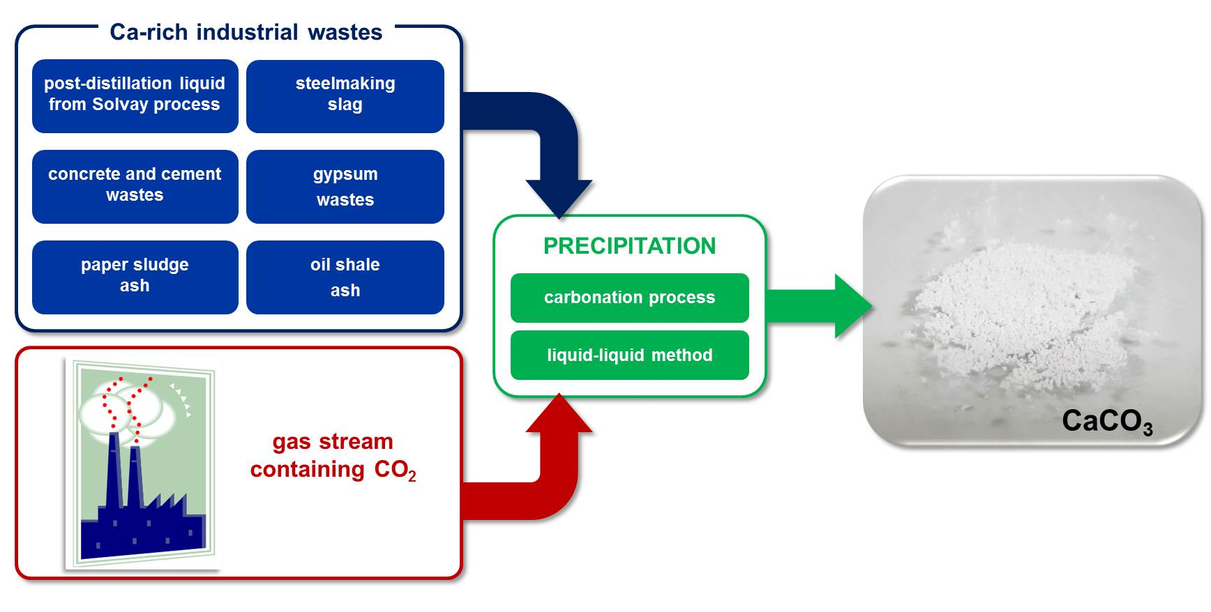
:Technologies for the management of various types of waste and the production of useful products from them are currently widely studied. Both carbon dioxide and calcium-rich waste from various production processes are problematic wastes that can be used to produce calcium carbonate. Therefore, the purpose of this paper is to provide an overview about the state of the development of processes that use these two wastes to obtain a valuable CaCO3 powder. The paper reviews the current research on the use of post-distillation liquid from the Solvay process, steelmaking slag, concrete, cement, and gypsum waste as well as some others industrial Ca-rich waste streams in the calcium carbonate precipitation process via carbonation route. This work is an attempt to collect the available information on the possibility of influencing the characteristics of the obtained calcium carbonate. It also indicates the possible limitations and implementation problems of the proposed technologies.

1. Introduction
Carbon dioxide is the main anthropogenic greenhouse gas [1]. The rapid economic growth resulted in an increase in energy demand and, consequently, an increase in the consumption of fuels, in particular fossil fuels such as oil, coal, and natural gas [2,3]. During their combustion, large amounts of CO2 are emitted into the atmosphere, which has an adverse effect on the environment and is the cause of global warming. There is a strong pressure on the EU countries to make their economies more energy-efficient and zero-emission. However, despite this fact, the projected global coal production continues to increase by around 3%, and the global carbon-related CO2 emissions from the energy sector will increase by 0.1% annually between 2015 and 2040 [4]. It is not surprising that numerous studies are focused on the management of waste gaseous carbon dioxide [5,6]. Carbon capture and storage (CCS) and carbon capture and utilization (CCU) technologies are the most popular processes to reduce CO2 emissions [7,8,9] and play an important role in meeting the global targets specified at COP25 [10]. In the case of both technologies, three main CO2 capture systems depending on the type of combustion process can be distinguished, post-combustion, pre-combustion, and oxyfuel combustion [6,8,9]. The choice of capture technology depends on the type of plant, i.e., the composition of the exhaust gas [11,12]. Post-combustion technology is the simplest to implement and is mainly based on chemical absorption [9,13,14]. Thus, this option is usually used as a modification to existing power plants. However, due to the low CO2 content in flue gases (4% in the case of natural gas combustion, 7–14% in the case of coal combustion), it is relatively expensive to obtain a gas stream with more than 95% CO2 using this technology. This is due to the fact that low CO2 concentration negatively affects the capture efficiency [15].
CCS technology is applicable to large CO2 point emission sources and involves the capture of waste CO2 from plants, including power plants or cement factories and then its transport to the storage site [11,16]. Most often, waste CO2 is stored in geological formations. The advantage of CCS technology is its high CO2 capture efficiency, which is usually above 80% [15]. However, large-scale deployment of CCS technology is not widespread so far due to both economic and technical barriers. First of all, the main obstacle is the unprofitability of such technology, as it requires a large financial investment [17]. Moreover, in some countries such as Norway, Great Britain, India, or Brazil, the geological possibilities for CO2 storage are very limited, which increases the costs of transport and injection, making the CCS solution an unrealistic option [18].
In order for CO2 capture to be a cost-effective process, either more efficient absorbents than commonly used should be applied, or alternative technological strategies should be implemented. In recent years, many alternatives to conventional CCS technologies, such as CCU, have been proposed [19,20,21]. Such technologies allow for reuse of captured CO2, which may partially offset the total cost of carbon capture and storage [16]. CCU technology includes CO2 absorption from anthropogenic emissions and its use as a substrate for the synthesis of valuable products such as concrete, plastics, fillers, or reagents for chemical synthesis [4,7,22,23,24]. One of the processes in which waste carbon dioxide from various sources can be applied as a substrate is carbon mineralization. An overview of mineral carbonation and its market potential has recently been presented [25] and an economic analysis of the various methods of CO2 utilization has been prepared by Hepburn et al. [26]. They show that mineral carbonation is one of the methods that comes closest to large-scale commercialization due to thermodynamically favored and economic considerations. Furthermore, it is possible to use numerous industrial wastes as other substrates when the product of the mineral carbonation is calcium carbonate. Such solution ensures effective recycling of both gaseous CO2 and liquid industrial waste, and in addition obtained final product can be applied in many industries [25].
This paper presents the current state of knowledge regarding the reuse of waste gaseous CO2 and selected Ca-rich waste in the calcium carbonate precipitation process. Presented methods are mainly based on the applying of industrial residues for CO2 capture by indirect methods and with the addition of additives. The use of post-distillation liquid from the Solvay process, steelmaking slag, concrete, cement, and gypsum wastes as well as some others industrial waste as calcium source has been discussed. The analysis of the conducted studies available in the literature focuses mainly on the characteristics of the obtained calcium carbonate particles and its purity. This is due to the fact that these factors are decisive when considering the commercial use of CaCO3 and the purity of precipitated calcium carbonate (PCC) needs to be above 99.9% (wt.) if it is to be applied in any commercial application. The possible encountered implementation problems of the proposed technologies were also considered.
2. CaCO3 Precipitation Methods
2.1. Carbonation Method
Carbonation is the main method used for the production of calcium carbonate on an industrial scale. This process involves the introduction of gaseous carbon dioxide into the reaction mixture being an aqueous solution containing calcium ions. Calcium hydroxide suspension (gas-suspension system) is used as the source of Ca2+ ions and in this case the alkaline environment causes CO2 to be easily absorbed [27]. Equation (1) provides the overall reaction:
The alternative is a gas-liquid reaction with a Ca2+ ion source in the form of an aqueous calcium salt solution such as CaCl2 and with the presence of absorption promoter such as amines or ammonia. In the presence of ammonia, the overall reaction presented in Equation (2) occurs in the solution:
Generation of supersaturation in solution, and consequently induction of calcium carbonate crystals nucleation and growth is possible due to CO2 absorption, which rate is the limiting factor. Ammonia hydrolysis results in the formation of hydroxyl ions. Bicarbonate ions are formed rapidly by the direct reaction between CO2 and OH− ions, after which they are transformed to carbonate ions. The last stage is the reaction between Ca2+ and CO32−, whereby CaCO3 is precipitated [28]. Changes in the composition of the aqueous phase cause a change in the solubility of carbon dioxide, which affects the driving force of absorption [29]. The rate of CO2 absorption in aqueous solutions, in turn, has an impact on the rate of chemical reaction between carbonate and calcium ions, and depends on parameters such as mass transfer coefficient, equilibrium and actual CO2 solubility, and contact liquid gas. When the absorption of carbon dioxide is accelerated, the rate of precipitation increases as well [29]. Temperature is an important parameter influencing the course of the calcium carbonate formation. The solubility of CO2 in solution is described by Henry’s law and the increase in temperature results in a decrease in CO2 solubility, and thus in a decrease in the rate of CO2 absorption [30]. On the other hand, the reactions of CaCO3 formation with the use of gaseous CO2 are exothermic, i.e., with the release of heat. Therefore, most of the research is conducted under moderate temperature conditions, which favors the CO2 transfer from the gas phase to the liquid phase.
2.2. Liquid-Liquid Method
Another method of calcium carbonate production used in industry is the liquid-liquid process in which aqueous solutions containing calcium and carbonate ions are mixed [31]. It is often used in laboratory tests due to the ease of controlling process variables [32]. In the literature, a lot of studies can be found in which aqueous solutions of CaCl2 and Na2CO3 [33], as well as Ca(OH)2 and H2CO3 [34] are used. The source of carbonate ions can also be (NH4)2CO3, while calcium acetate as the source of Ca2+ ions [35] may be applied. An example of a general reaction can be written as Equation (3):
3. Calcium-Rich Wastes
3.1. Post-Distillation Liquid from Solvay Process
The Solvay method used for the production of sodium carbonate (soda ash) is one of the processes in which waste is a serious environmental problem [36]. The main and most problematic waste generated during this process is post-distillation liquid. It contains mainly water (956 kg/m3 of waste stream), calcium chloride (112 kg/m3), and unconverted sodium chloride (56 kg/m3), but also calcium carbonate (10 kg/m3), calcium hydroxide (7 kg/m3), silicon oxide (3 kg/m3), calcium sulfate (1 kg/m3) and ammonia (0.1–0.01 kg/m3) [37,38]. The post-distillation liquid flows out the stripping columns and is directed to the ground settlements called “white seas” or directly to natural water reservoirs [37,39]. However, such activities contribute to the strong salinity of nearby groundwater with calcium chloride, as well as the pollution of natural water reservoirs and soil [39].
Due to the fact that Ca-rich waste from the Solvay process is liquid, it can be used directly as the reaction medium without carrying out a calcium ion extraction step. In this section, two possible paths of post-distillation liquid management for CaCO3 precipitation are discussed: using (i) liquid-liquid method with aqueous Na2CO3 solution and (ii) carbonation, in which gaseous waste CO2 can also be applied.
3.1.1. Precipitation Using Aqueous Carbonate Solution
In most studies, using a post-distillation liquid from the Solvay process containing calcium chloride, sodium carbonate is applied to precipitate CaCO3 as a source of carbonate ions. In this case, the occurring reaction is described by Equation (3). The sodium chloride solution resulting from this reaction, after filtering the calcium carbonate particles, can be recycled and reused in the soda ash manufacturing process [40].
In the research conducted by Kasikowski et al. [37], precipitation of calcium carbonate using calcium ions present in the post-distillation liquid and carbonate ions derived from an aqueous soda ash solution has been proposed. Soda from the Solvay process that does not meet the standards for dense or light soda ash is a substrate for preparing an aqueous Na2CO3 solution. Calcium carbonate in calcite form (chalk) obtained by such precipitation is used in the pharmaceutical and cosmetics industry because it is characterized by very high quality, especially low content of ferrous or ferric ions and sodium chloride. In addition, by using well-chosen conditions of the precipitation process, it is possible to obtain pure semi-brine above the precipitated CaCO3. After filtering off calcium carbonate, the semi-brine can be recycled and reused in the production of soda ash or evaporated salts after saturation. For example, about 4000 tons of calcium carbonate is produced annually in the Janikowo Soda Factory (Janikowo, Poland) using this method, and this amount depends on the demand. This technological solution results in a profit of $560,000 per year [37]. In another research, Białowicz et al. [41] used a post-distillation liquid from the Janikowo Soda Factory and sodium bicarbonate solution for the precipitation process of calcium carbonate in the presence of urea. CaCO3 powder was obtained with very low packing density. Moreover, both the increase in reaction time and the increase in urea concentration resulted in an increase in bulk and packing densities [41].
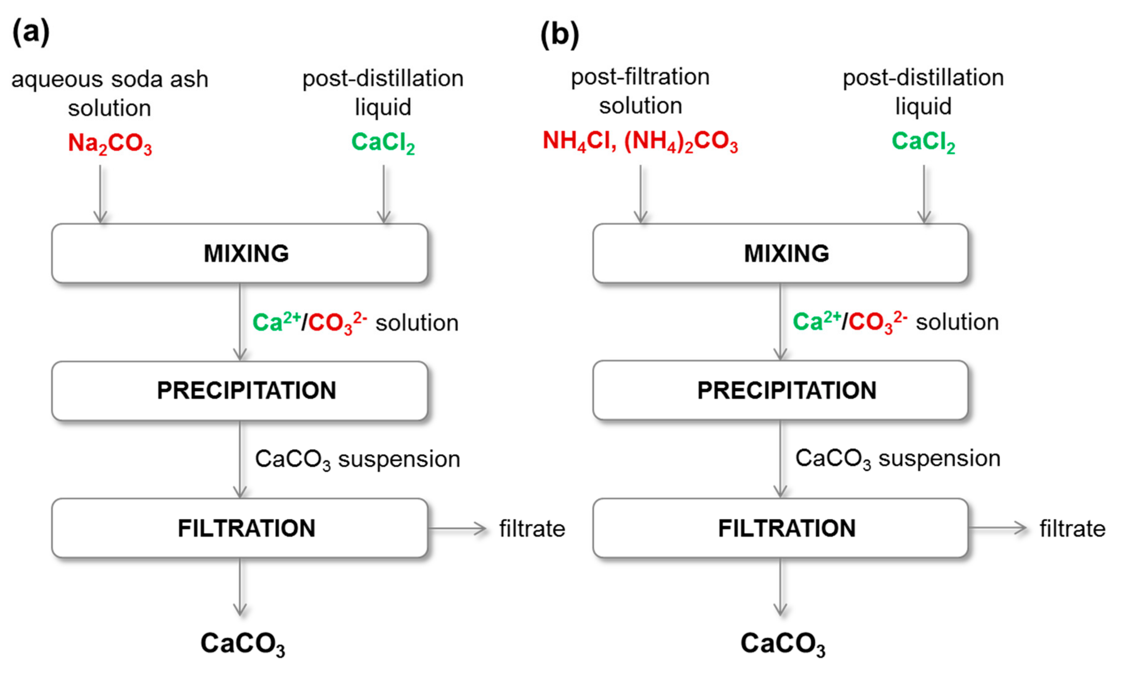
Somani et al. [40] studied the effect of process temperature and sodium carbonate concentration on the crystallization of individual CaCO3 polymorphs. A model post-distillation liquid with a composition of 1.25 M CaCl2 and 0.85 M NaCl was used. Only calcite and aragonite are formed in such a system, but no crystallization of vaterite has been observed. In addition, the increase in sodium carbonate concentration resulted in an increase in the calcite content of the precipitated calcium carbonate. However, the use of diluted Na2CO3 solution caused the appearance of aragonite. The formed CaCO3 particles had a rhombohedral and needle-like shape [40]. However, this work did not contain information on the efficiency of the precipitation reaction, as it is not known how many calcium ions present in the initial reaction mixture were consumed to precipitate CaCO3. A diagram showing the calcium carbonate precipitation process by the liquid-liquid method using post-distillation liquid from the Solvay process and an aqueous solution of sodium carbonate is presented in Figure 1a.
Another method proposed by Trypuć et al. [42] is based on CaCO3 precipitation using a post-distillation liquid containing calcium ions and post-filtration solution as a source of carbonate and ammonium ions. Figure 1b shows a diagram of the CaCO3 precipitation process carried out by this method. Post-filtration solution, which is the waste generated after filtering the NaHCO3 precipitate in the Solvay process, consists of CO32− (0.69 mol/dm3), NH4+ (4.962 mol/dm3), Cl− (4.389 mol/dm3) and SO42− (0.012 mol/dm3). It was found that increasing the time of the post-filtration liquid dosage into post-distillation liquid causes the increase of both packing and bulk densities. Moreover, the formation of agglomerates and only a small amount of single calcium carbonate crystals was observed. In this method, the post CaCO3 filtration liquid contains NH4Cl, (NH4)2CO3, and unreacted NaCl. NH4Cl and NaCl can be recovered from this solution using evaporation and fractional crystallization processes. Valuable solid products are obtained in this way. For example, the recovered sodium chloride can be recycled to the Solvay process for brine preparation or used in other industries. Thanks to this it is possible to fully use of Cl− ions, which in a conventional process are directed as waste to natural water reservoirs. In addition, the proposed precipitation of calcium carbonate at temperatures not exceeding 50 °C results in obtaining chalk with the desired physicochemical properties due to easy control of process conditions [42]. Gao et al. [43] also proposed a method for utilizing both post-distillation liquid and post-filtration solution to precipitate calcium carbonate in the presence of selected surfactants (CTAB, SDBS and Brij 35). In this process, spherical ultrafine precipitated calcium carbonate was obtained. The results show that the presence of selected surfactants had a significant effect on the mean particle size. Without the addition of surfactants, the average particle size was about 5.5 μm, while the presence of these additives results in the formation of fine particles with a size of about 1.5 μm. Furthermore, the authors suggest that the use of such technology allows soda factories to obtain benefits such as the sale of CaCO3, but also release from fees for environmental pollution [43].
Mikhailova et al. [44] proposed the calcium carbonate precipitation method with the use of post-distillation liquid and excess of mother solution from Solvay process. The authors determined the optimal precipitation conditions leading to the obtaining of calcium carbonate with characteristics qualifying it for commercial applications. It has also been estimated that the application of the proposed process enables the production of 5000 tons of CaCO3 per year, taking into account the production of liquid waste from the Solvay process in Ukraine [44].
Table 1 summarizes the process parameters of the selected calcium carbonate precipitation technologies using a post-distillation liquid and an aqueous sodium carbonate solution (liquid-liquid method). All presented methods were conducted under atmospheric pressure, while the temperature was in the range of 5 to 95 °C. The use of higher temperatures for liquid-liquid processes is due to the fact that the reaction (Equation (3)) is endothermic. In this case, heat is absorbed from the surroundings, so that elevated temperatures favor this reaction.
3.1.2. Precipitation Using Flue Gas
Technology that allows the use of flue gases to precipitate calcium carbonate from post-distillation liquid has also been proposed [45]. It can be a variation of the wet-lime method, in which the absorption of combustion gases arising during combustion occurs in the overflow of distiller waste [37]. In the Solvay process, an excess of lime milk is added during the regeneration of ammonia from the filtration liquid. As a result, the distillation waste is strongly alkaline, which promotes the absorption of acid flue gas. However, it should be noted that several products are obtained, depending on the reacting gas component.
The absorption of carbon dioxide results in the formation of calcium carbonate, while the absorption of sulfur oxides causes the precipitation of calcium sulfate and sulfite. The reactions that occur during the absorption of the flue gas are presented below (Equations (4)–(9)):
It is also possible to simultaneously use waste gases containing carbon dioxide and post-distillation liquid from the Solvay process. However, of the individual components of distillation waste, only Ca(OH)2 can react with CO2 according to Equation (4). Calcium chloride, although its concentration in the liquid is still high, does not react with carbon dioxide. This is because CaCl2 is the salt of a strong acid while carbonic acid is a weak acid. Therefore, to create conditions conducive to CO2 absorption and the formation of carbonate ions in the solution, an absorption promoter, such as amines or ammonia, should be added to facilitate the CO2 transfer from the gas phase into the liquid phase [37,46].
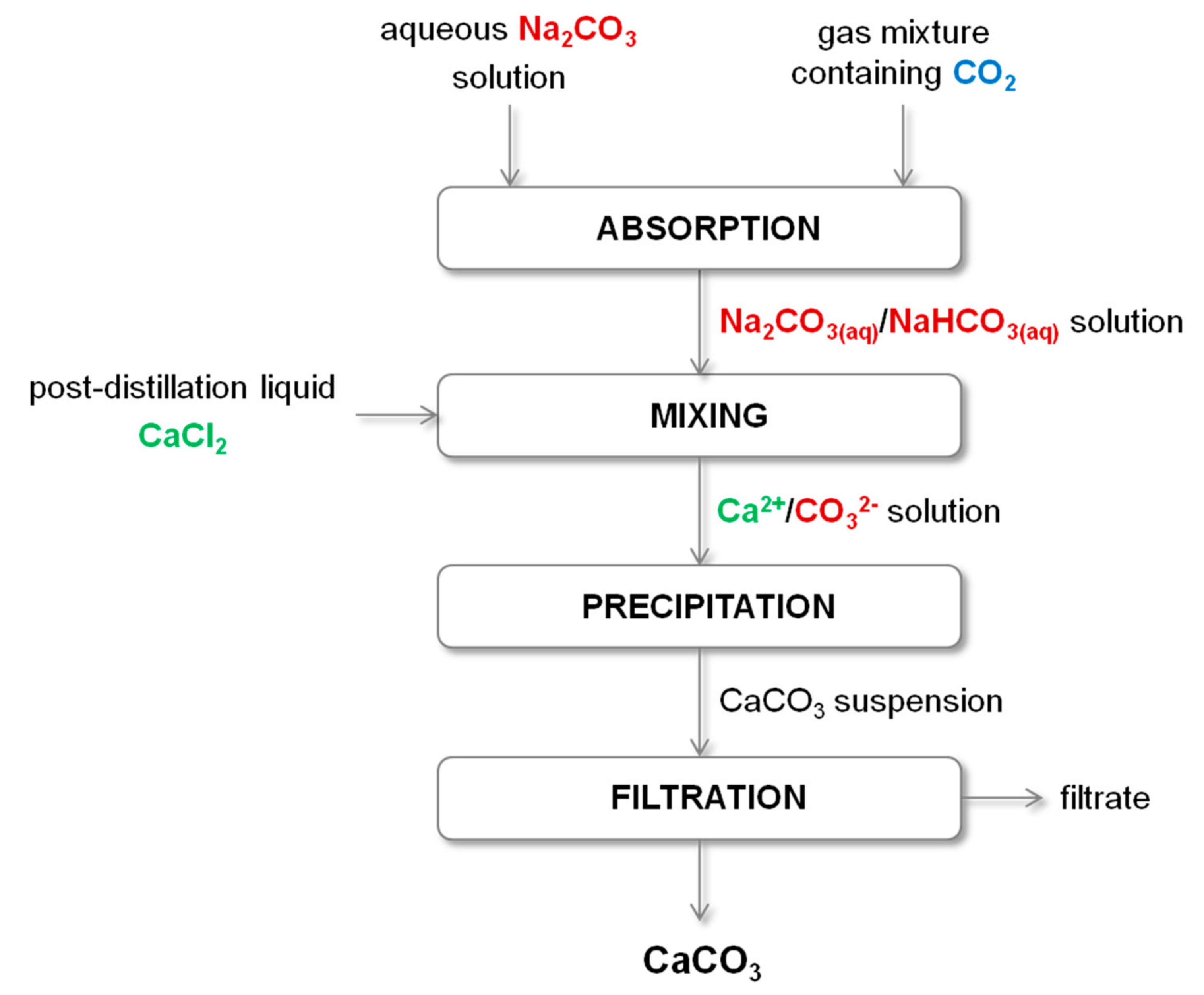
Barzagli et al. [22] proposed a semi-continuous technique for capturing carbon dioxide from a gas mixture applying a dilute aqueous Na2CO3 solution and CaCl2 aqueous solution obtained as a by-product in the Solvay process. Firstly, sodium carbonate solution is saturated with CO2 and then such mixture can react with calcium chloride solution. Using this method, 80% absorption efficiency is obtained and high-quality calcium carbonate is precipitated. This technique may allow to minimize the energy demand due to the fact that the process is carried out at room conditions. By using this method, the main disadvantages of processes using aqueous solutions of alkanolamines, ammonia, or alkali metal carbonates are avoided. There is no energy-consuming regeneration of the absorbent, or costs associated with the evaporative loss of ammonia and oxidative and thermal degradation of amines [22]. The scheme of this method is presented in Figure 2.
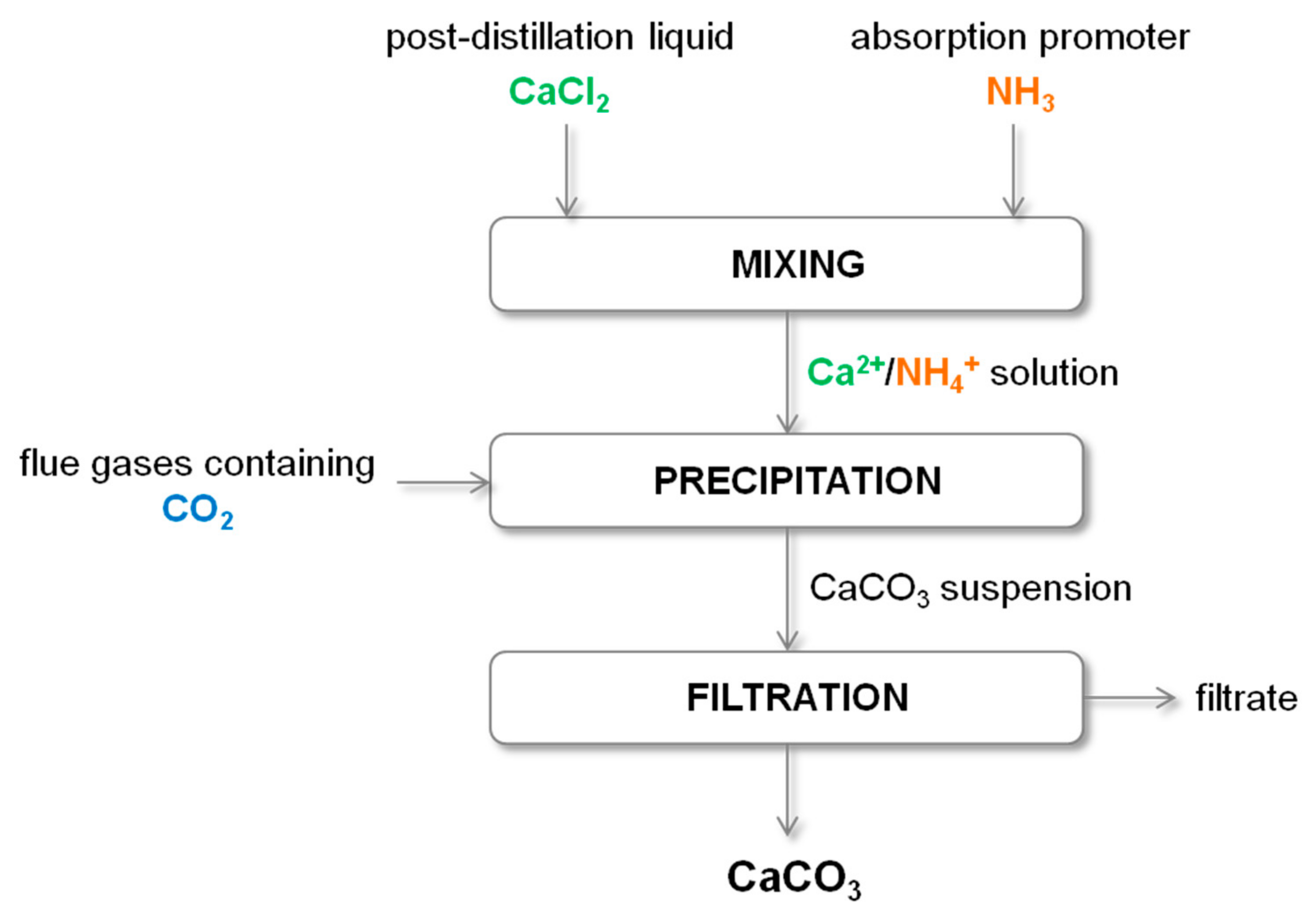
In another study, a method for CO2 sequestration from flue gases using a model post-distillation liquid from Solvay process in the presence of ammonia has been proposed [47]. The scheme of this method is shown in Figure 3. As a result, calcium carbonate precipitates mainly in the form of vaterite and is a valuable product that can be used, among others, for paper production or as an adsorbent for heavy metal ions removal [48]. An increase in ammonia concentration favored CO2 and Ca2+ consumption. About 80% of calcium ions from the post-distillation liquid and about 83% of carbon dioxide from a mixed air-CO2 gas stream were consumed under the most favorable conditions of this one-stage precipitation process [47]. After filtering off the CaCO3 particles, a waste solution containing ammonium chloride is formed. However, it can be used to recover metal ions or as a leaching agent [49,50]. The NH4Cl solution can also be applied in the carbon capture and storage process [51].
Li et al. [52] proposed a new technology for processing post-distillation liquid and waste gaseous carbon dioxide. Calcium chloride is converted into calcium carbonate and hydrogen chloride based on the reactive extraction and crystallization process. Isoamyl alcohol and commercial tertiary amine N235 were used as the extraction system. The conversion rate of calcium chloride under optimal process conditions is 75%.
During this method, the overall reaction described by Equation (10) occurs. The addition of a tertiary amine results in a constant shift of equilibrium in Equation (10) in the right direction:
An important issue to consider in processes using liquid waste are the additional compounds and ions present in them. In the case of post-distillation liquid from the Solvay process, they are, among others, Na+, K+, Mg2+, Al3+ cations, and SO42−, NO3− anions. The influence of these ions on CaCO3 precipitated by carbonation was studied by Dong et al. [53]. It turns out that Na+, K+, and NO3− have a very weak effect on calcium carbonate, and therefore small amounts of these ions can remain in solution without consequences and no removal is necessary. However, Mg2+ and SO42− can adsorb on the crystal surface at the early crystallization stage and inhibit the transformation of vaterite into calcite [54]. Magnesium ions also promote the growth of aragonite and inhibit calcite precipitation [55]. Therefore, the content of these ions should be reduced to 1% before using the liquid as a precipitation medium. In addition, a significant amount of very small particles with a diameter less than 1 μm are due to the presence of SO42−. Accordingly, these anions must be removed before industrial production [53].
Table 2 summarizes the process parameters of the selected calcium carbonate precipitation technologies using a post-distillation liquid and gaseous carbon dioxide (carbonation process). When analyzing the process parameters of all presented methods, it is worth noting that in each case the process pressure is atmospheric, while in most cases the temperature is moderate, which corresponds to the conditions most favorable to exothermic CO2 absorption.
3.2. Steelmaking Slag
Steel production is one of the largest industries in the world where wastes are a serious problem [56,57]. Most of the steel is produced by an integrated technological path, in which limestone or burnt lime is applied to remove impurities from molten iron and crude steel. As a result of this treatment, steelmaking slags, which mainly consist of calcium silicates and calcium oxide, are formed. Their specific composition depends on the production process. Steelmaking slags are used, among others, as lime in agriculture, in road construction as a substitute for gravel [58], or in cement and concretes as an additional cementing material [59]. However, it is not always possible to use them economically due to stringent environmental regulations. In such situation, they are problematic postproduction waste. Therefore, alternative methods of utilizing steelmaking slag are sought [60]. One of the proposed approaches is the use of this waste for the production of calcium carbonate by carbonation route (according to Equations (11) and (12)) due to the high content of calcium oxide. The resulting CaCO3 could replace the limestone used for purification in the steel industry. However, if the manufactured product were of sufficiently high quality, then it could be sold and used in other industries [61]:
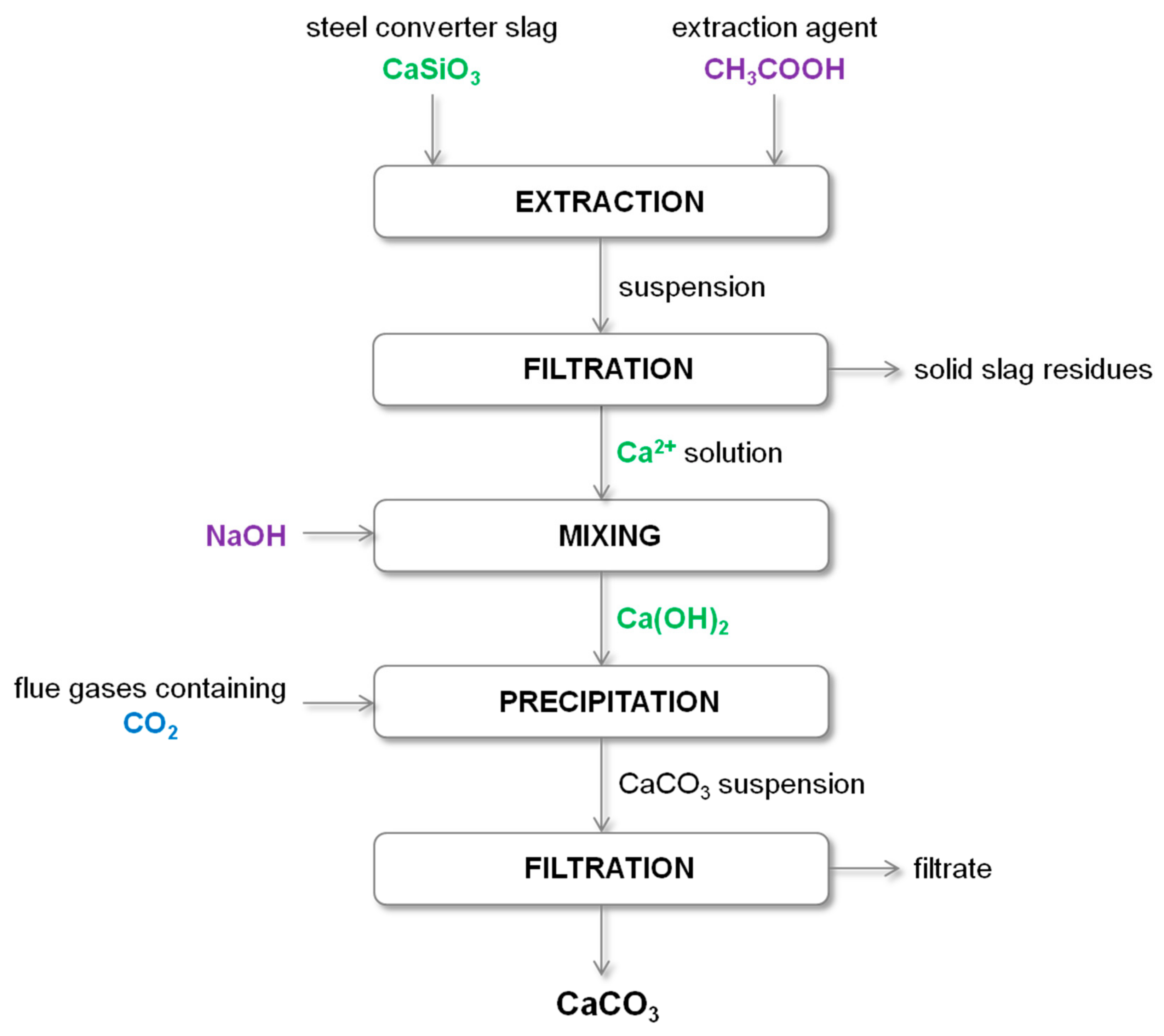
Potentially, calcium silicate (wollastonite) is the largest source of calcium ions in steelmaking slag. According to Kojima et al. [62], the rate of direct CO2 reaction with CaSiO3 is too slow to be practically used. Thus, to use calcium from CaSiO3, as well as to prevent unwanted pollution, the separation of calcium from the slag must first be carried out. It results in an accelerated reaction rate between Ca2+ and gaseous CO2. One of the methods reported in the literature is the dissolution of calcium silicates with acetic acid according to Equation (13). A solution of calcium acetate and solid silicon oxide are formed. Gaseous CO2 is then introduced into the solution to precipitate calcium carbonate by carbonation according to Equation (14). The acetic acid added in the first stage is regenerated and can be reused [63]. Furthermore, flue gases from concentrated emission sources can be a source of gaseous CO2, which allows for its sequestration and removal:
Eloneva et al. [61] investigated CaCO3 precipitation process using gaseous CO2 and waste steel converter slag, the diagram of which is presented in Figure 4. In this research, a modification of the method proposed by Kakizawa et al. [63] was used because acetic acid produced simultaneously with calcium carbonate prevents the precipitation of most calcium from the solution in the case of low acetic acid concentrations (30% or less). Therefore, the addition of sodium hydroxide was used to prevent the formation of acetic acid and favors the formation of CaCO3. This method is described in Equations (15)–(17). When a higher concentration of acetic acid is used, a greater efficiency in leaching of calcium ions is obtained, but at the same time the dissolution of other undesirable impurities (like silicon and iron) is increased. 86% of Ca2+ ions present in the solution were consumed to precipitate calcium carbonate, while the obtained product had a purity of 99.5–99.8%. In addition, CO2 concentration has no effect on either the quality or the amount of CaCO3 precipitated. This is very beneficial because flue gases can be used directly in this process without prior CO2 separation and purification. The lowest CO2 concentration (10% vol.) resulted in longer precipitation time, but this effect can be eliminated by raising the temperature or increasing the flow rate. This is the solution to the problem of low concentration of carbon dioxide in the exhaust gas. It has been estimated that using the proposed method, a maximum of 42,000 t per year of pure CaCO3 can be obtained from the annual production of waste steel converter slag from the Raahe Works factory (Raahe, Finland). Although this process is also suitable for other steel plants, the necessary consumption of NaOH and CH3COOH results in too high process costs, so its implementation cannot be economical. This problem can be solved by replacing acetic acid with a salt solution and sodium hydroxide with a certain alkaline liquid waste stream, which would reduce the cost of the process [61]:
In another method of using steel converter slag for the production of CaCO3 by carbonization, calcium ions are extracted from this waste with an aqueous solution of ammonium chloride, ammonium nitrate and ammonium acetate [58,64,65] using different slag to liquid ratios. To prevent the escape of ammonia, Ca2+ extraction is conducted in a closed reactor. The carbonization process is carried out in an open reactor at room temperature and atmospheric pressure, which reduces energy demand and costs [64]. The resulting calcium carbonate has high quality. The main problem of the proposed method is the formation of waste residual slag. Finding a method for recycling this waste can generate additional process costs [66]. It has been estimated that from 4.7 ton steel converter slag it is possible to produce 2.3 tons of CaCO3 with simultaneous production of 3.4 tons of residual slag. The analysis was made on the example of Raahe Works, which produces about 200 kt steel slag per year. Assuming the consumption of all waste slag, 42,000 tons of CO2 can be bound in the form of about 96,000 tons of calcium carbonate per year, which will generate an income of around 10 million euro per year [64]. However, it should be noted here that these estimates do not take into account other costs of running the process. Notwithstanding, this solution has great economic potential. Studies using an aqueous solution of ammonium chloride as the extraction agent for Ca2+ ions have also been carried out [51,67,68]. Currently, it is the most commonly used method, because it turned out to give the highest Ca2+ selectivity [69].
Table 3 summarizes the reaction conditions for calcium carbonate precipitation depending on the type of slag and the extraction agent and presents the characteristics of the obtained product. Atmospheric pressure was used in most of the research, while the tested temperature range was 20 to 80 °C. Due to the fact that CO2 absorption is an exothermic process, the increased temperature does not have a positive effect on it, although it has an influence on the polymorphism of the obtained CaCO3. Moreover, the use of elevated temperature generates additional costs of the process. As the literature shows, carbonation processes using steelmaking slag as a source of calcium ions and gas streams containing CO2 allow to obtain highly pure calcium carbonate, which can be used as a substrate in other industries. However, there are many economic issues to consider as to whether the proposed methods are worth implementing.
3.3. Concrete Wastes
Concrete as the main building material in the world, is manufactured in an amount of 4000 Mt per year (2017) and its market increased by 2.5% annually, while producing approximately 7% of global carbon dioxide emissions [71,72]. For example, the production of 1 kg of Portland cement generates more than 0.8 kg of CO2. Waste concrete from demolished buildings and other constructions is a serious problem, because their quantity is constantly increasing. Therefore, possible technologies for its utilization or reuse are sought [73]. There is a lot of research regarding the use of waste concrete for the production of PCC [74]. The potential amount of calcium that can be recovered from waste concrete depends on the content of this element in cement. For example, Portland cement contains 46.53% wt. of calcium [75], whereas concrete consists of 37% wt. coarse aggregate, 33% sand, 19% cement, and 11% water. Therefore, 88 kg of calcium can be recovered from a ton of Portland cement-based concrete [76]. Commonly used processes for the chemical recovery of calcium from waste concrete include three energy-intensive stages: crushing, milling, and leaching [74]. For the production of PCC from waste concrete, numerous studies have been conducted on various leaching agents. Water [77,78,79], acetic acid [80], ammonium salts [69,81], and nitric acid [82] have already been used. These solvents showed a relatively low calcium leaching efficiency of less than 60%, although higher pressure (about 10 bar) was used to improve the water leach. In addition, when producing CaCO3, it is recommended to use an even lower yield (around 30%) to avoid contamination of the final product. An alternative solution is to use a stronger acid, e.g., hydrochloric acid [83,84], which maximizes the leaching efficiency. However, carbonization does not occur in a solution with a low pH, so when using an acid as an extraction agent, a base, such as ammonia, must be added to the resulting Ca-rich solution [85,86].
Jo et al. [87] examined the impact of the type of extraction agent on the waste concrete carbonation process. In this research, aqueous solutions of ammonium chloride, acetic acid, hydrochloric acid, and pure deionized water were used, and the processes were carried out at room temperature and atmospheric pressure. The results indicate that the type of extraction agent has no effect on calcium carbonate precipitation, because in each case the resulting precipitate consisted mainly of CaCO3 in the form of a mixture of rhombohedral calcite and spherical vaterite. However, the weight fractions of individual polymorphs were not determined. However, when NH4Cl solution was used, the highest extraction and carbonization efficiency were obtained.
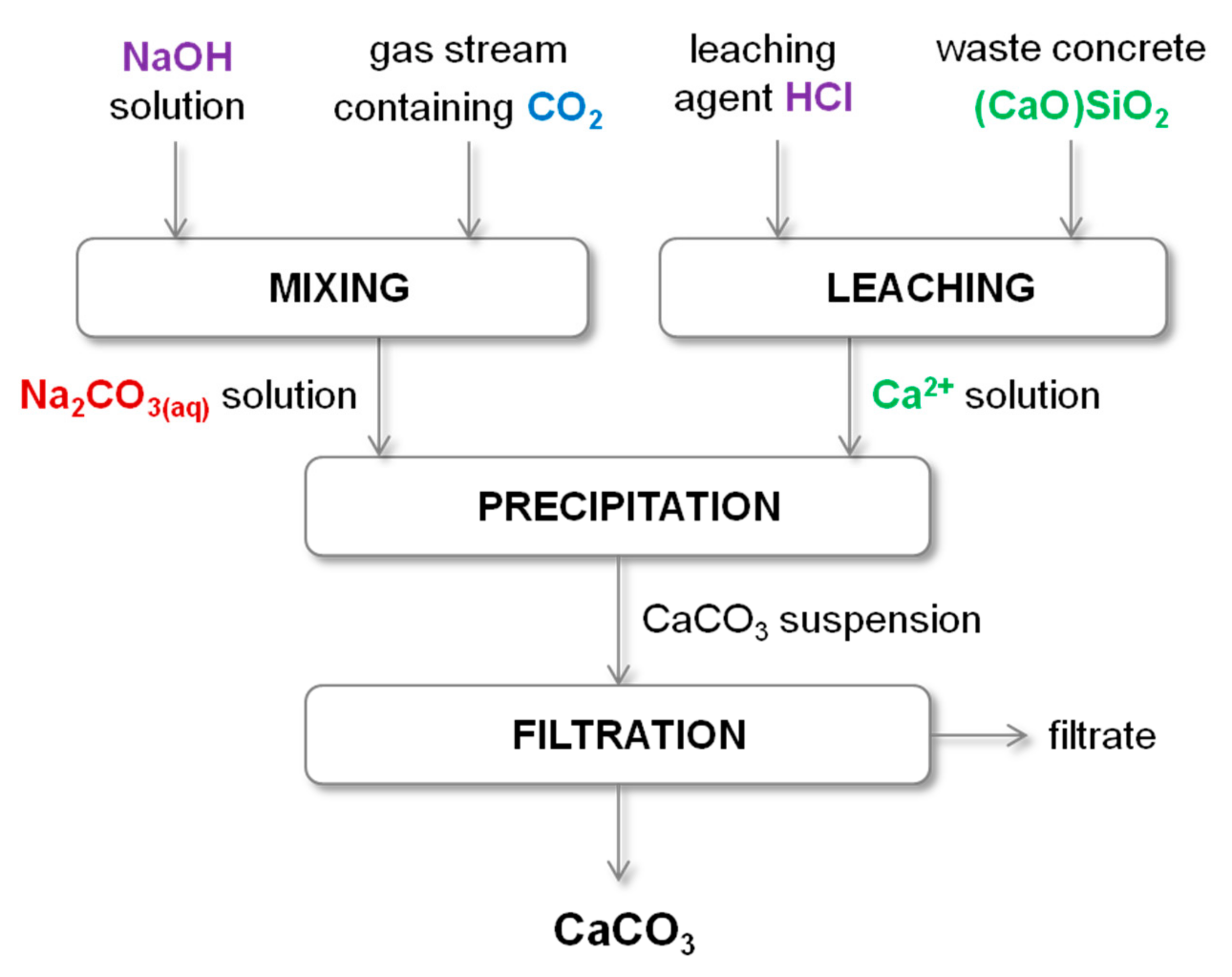
Van der Zee and Zeman [74] proposed a method of producing precipitated CaCO3 from waste concrete, where HCl was used as the leaching agent. Precipitation of calcium carbonate was carried out in a separate reactor by mixing the calcium-rich solution obtained by leaching and aqueous sodium carbonate solution. Na2CO3 solution can be produced by introducing any gas stream containing carbon dioxide into an aqueous NaOH solution. The overall reaction is shown in Equation (18) and the diagram of this process is shown in Figure 5. The HCl and NaOH used in this process were regenerated by membrane bipolar electrodialysis, which is an additional step requiring energy input. The authors suggest that reducing the costs of this stage can be achieved by using HCl concentration lower than 0.5 M:
Another important problem in the concrete industry is the formation of concrete sludge (waste cement) when fresh concrete is used to manufacture construction or concrete elements [88]. Concrete sludge is a fine fraction recovered during the recycling of waste concrete as a coarse aggregate [76] and has a composition very similar to fresh concrete diluted with water, because it is calcium-rich and strongly alkaline. An example composition of concrete sludge is water (77.1% wt.), CaO (17.2% wt.), SiO2 (3.2% wt.), Fe2O3 (1.9% wt.) and Al2O3 (0.6% wt.) [89]. Usually, the utilization of this waste consists in its reuse as an additive to road materials or its storage in landfills [89]. However, the first solution is an expensive process because it requires the separation of solids from liquids, resulting in a strongly alkaline liquid that must be neutralized with acid. On the other hand, the storage of concrete sludge in landfills is environmentally harmful. Therefore, alternative methods are sought to dispose of problematic cement waste [89].
One of the solutions is the use of concrete sludge as a raw material in the carbonation process, which results in the precipitation of calcium carbonate. Cement hydration products, such as calcium hydroxide, calcium silicate hydrate, and calcium aluminate hydrate, react with the gaseous carbon dioxide introduced and dissolved in the aqueous solution [90,91]. Occurring reactions are described in Equations (19)–(21):
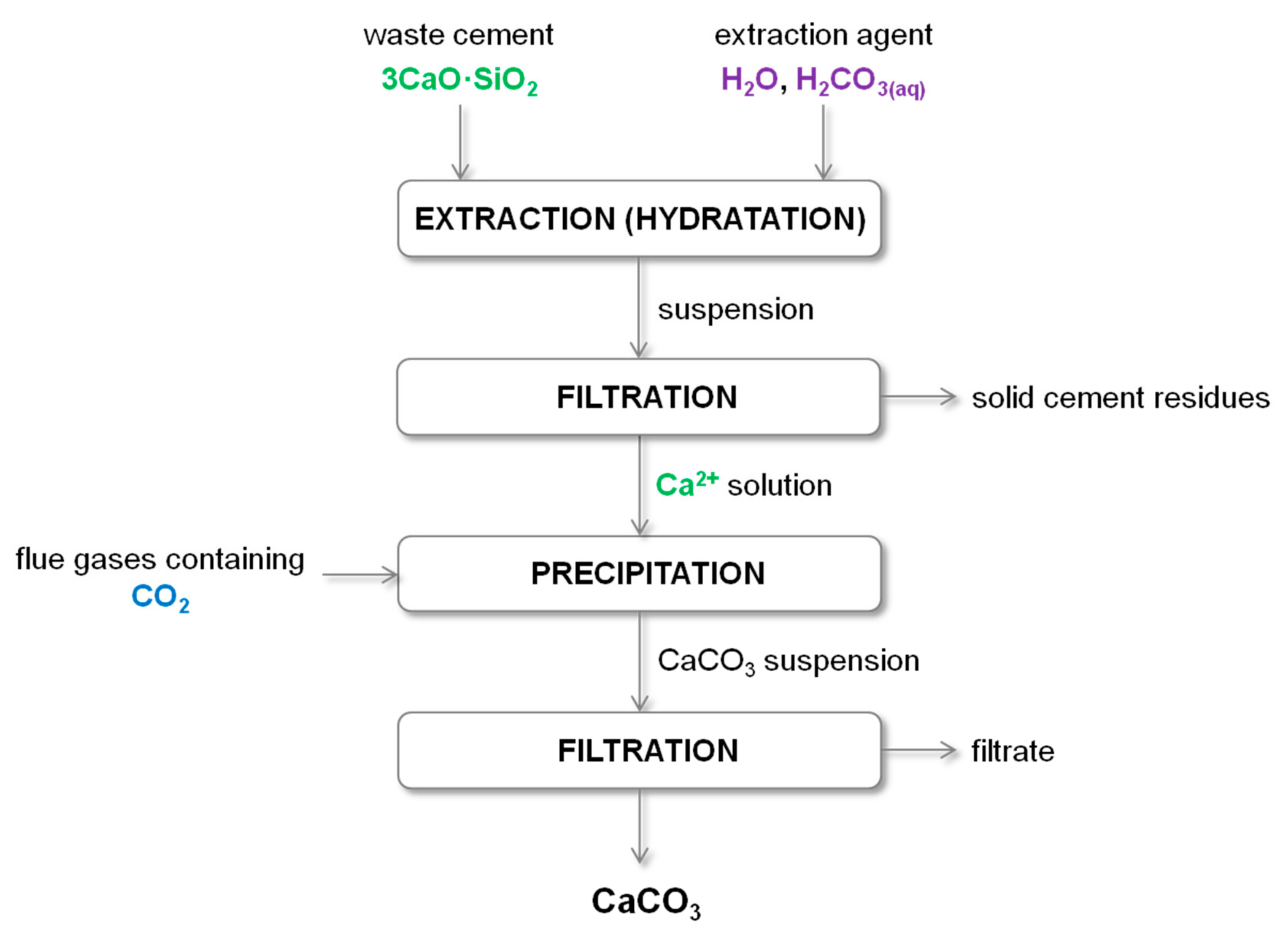
Iizuka et al. [92] conducted research on bench-scale installation for the concrete sludge recycling process using gaseous CO2. Industrial concrete sludge and flue gas from oil combustion boilers were applied. Authors proposed a two-stage recycling method for concrete sludge, the diagram of which is presented in Figure 6. The first step is the extraction of calcium ions, which involves diluting the concrete sludge with water (hydration) and extracting Ca2+ ions into the water phase assisted by mixing (Equation (22)). In another work, Ca2+ extraction from waste concrete was carried out by carbonic acid solution prepared using pressurized carbon dioxide [93,94]. The remaining precipitate is then separated from the extract. Gaseous carbon dioxide is introduced into the resulting calcium-rich solution, thereby precipitating calcium carbonate. Importantly, the proposed method can directly use fumes from the combustion of fossil fuels without purifying or compressing them. The solution formed after filtering the CaCO3 particles is neutralized with carbonic acid. In addition, the resulting calcium carbonate can be used in many industries. The feasibility of the proposed technology was also assessed. However, commercialization of this process has not been shown to be economically viable [92]:
The same research team designed and built a pilot installation for recycling concrete sludge and CO2 waste to precipitate calcium carbonate [89]. Concrete sludge from the production of piles and poles, boiler gas, and groundwater were used. The process had the same two stages as for bench scale [92]. Using this technology, it is possible to obtain high-quality CaCO3 with a purity above 97%, as well as to reduce CO2 emissions from waste gases. Importantly, this process is energetically beneficial because it is carried out at standard temperatures and atmospheric pressure, and moreover there is no need to purify the exhaust gas or increase its pressure.
Table 4 summarizes the process parameters of the selected calcium carbonate precipitation technologies using concrete waste or concrete sludge and gaseous carbon dioxide (carbonation process). All listed methods were carried out under atmospheric pressure. In the case of temperature, most of the processes were carried out at room temperature, while the influence of elevated temperature (30, 50, 70 °C) on the precipitation process was also investigated. When CO2 absorption is accompanied by an exothermic reaction (Equation (22)), the lower process temperature favors such a transformation.
3.4. Gypsum Wastes
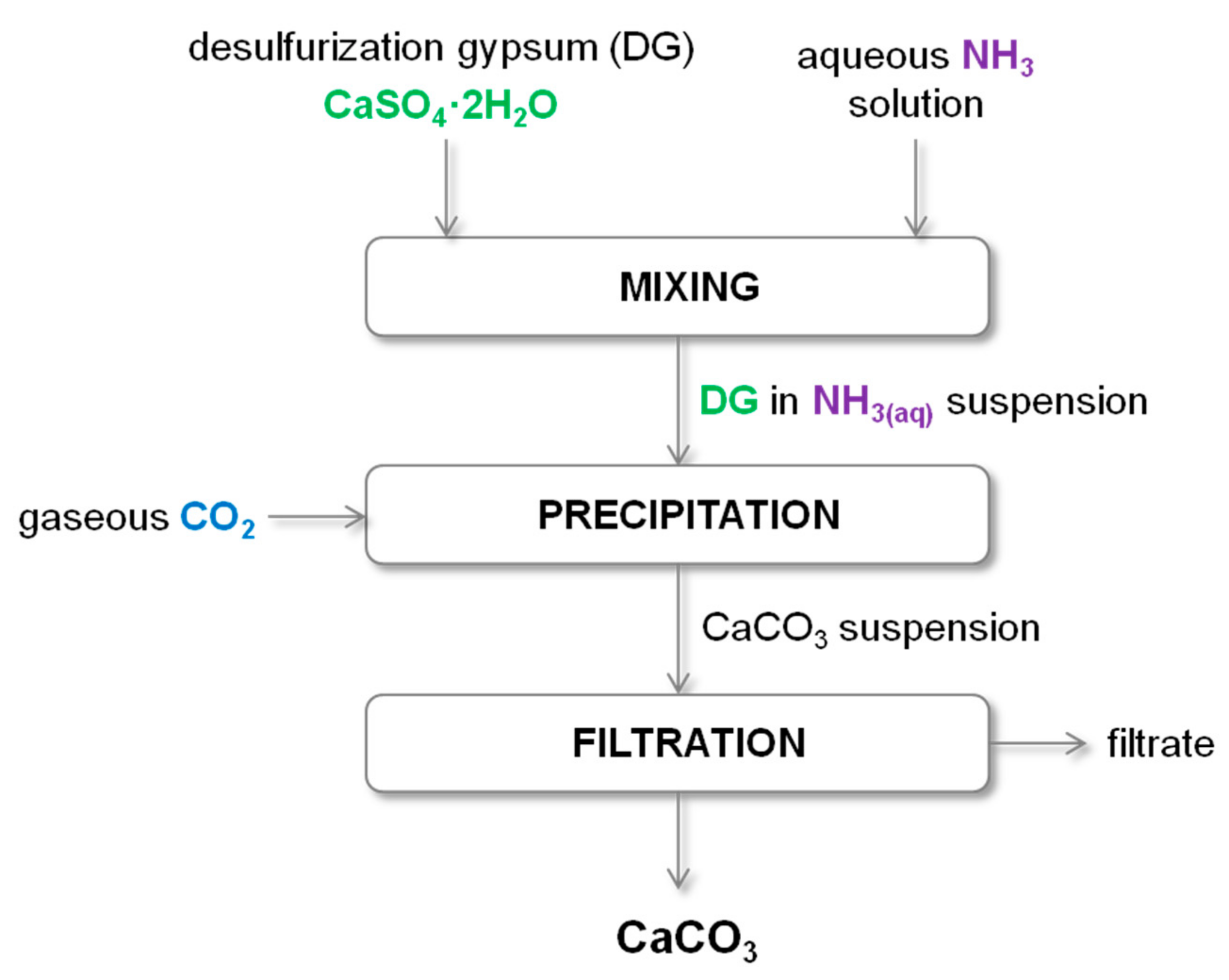
There are three types of gypsum waste, phosphogypsum (PG), desulfurization gypsum (DG), and red gypsum (RG). PG is produced during phosphoric acid production, DG is generated in power plants through a reaction between sulfur gas and lime or limestone sorbents in the desulphurization unit, while RG is the waste from processing ilmenite ore to obtain TiO2 particles. The waste PG and DG consist mainly of CaO, SO3, and water, as well as minor impurities such as Fe2O3, SiO2, and Al2O3 [95]. Due to the high calcium content, gypsum wastes have great potential to be used for CO2 sequestration and calcium carbonate production. The mineral carbonation of gypsum obtained during flue gas desulfurization (DG) proceeds according to the reaction in Equation (23). According to the reaction stoichiometry, in such a process for every 1 ton of produced ammonium sulphate, 0.9 tons of CaCO3 is generated and 1.6 tons of gypsum and 0.4 tons of CO2 are consumed [96]:
Song et al. [97] proposed the direct carbonation of DG process, which was carried out in ambient conditions using an aqueous ammonia solution. A diagram of this process is shown in Figure 7. DG is characterized by high carbonation reactivity at room temperature and atmospheric pressure [97]. The polymorphic form of CaCO3 obtained during direct and indirect carbonation was also compared. In the case of the direct process, the formation of a mixture of rhombohedral calcite and spherical vaterite was observed, with the vaterite content being dependent on the carbonation time. The longer the time, the greater the amount of vaterite in the resulting product. However, during the two-stage (indirect) process, the precipitated calcium carbonate was mainly in the form of calcite. Moreover, what is important, in the proposed direct carbonation process, obtained calcium carbonate was practically free of impurities, which allows for further use of such a product [97]. In another work, Song et al. [98] focused on the possibility of controlling the polymorphic form and morphology of calcium carbonate obtained during direct carbonation of DG using an aqueous ammonia solution. The controlling factor was the addition of ethanol to the reaction mixture under stoichiometric conditions and with an excess of ammonia. During both processes investigated by Song et al. [97,98], a pure and valuable product from industrial DG is produced. However, the problem is to obtain a small amount of CaCO3 crystals. Additionally, these research are focused mainly on the polymorphic form and morphology of calcium carbonate and do not contain any discussion about the efficiency of CO2 sequestration.
Table 5 summarizes the process parameters of the selected calcium carbonate precipitation technologies using waste gypsum and gaseous carbon dioxide (carbonation process). All presented processes were carried out under atmospheric pressure and at moderate temperatures (20–40 °C). Such conditions favor both CO2 absorption and the exothermic reaction (Equation (23)).
3.5. Other Ca-Rich Waste
There are several other examples of alkaline liquid waste in the literature that can be used as Ca-rich raw material for the production of CaCO3 by the carbonization method. Paper sludge ash (PSA) from paper manufacturing has a very small particle size, high pH (>12) [100] as well as high calcium content of about 22% wt. [101,102]. Kim et al. [102] conducted research on CO2 storage by indirect carbonation with PSA at room temperature and atmospheric pressure. In this work, various types of solvents for the extraction of calcium ions from PSA were investigated: acetic acid, hydrochloric acid, ammonium acetate, ammonium chloride, sodium citrate and water. Gaseous CO2 was introduced into the obtained extract to precipitate calcium carbonate. To increase the CO2 storage efficiency, additional steps such as pH swing or changing the amount of supplied CO2 were used. The results indicate that the highest CO2 capture efficiencies were obtained using acetic acid (324 kgCO2/ton PSA) and hydrochloric acid (297 kgCO2/ton PSA) by treating the extract with sodium hydroxide. In the case of the ammonium salts, efficiency in the range of 168–175 kgCO2/ton PSA was obtained. The lowest efficiency was recorded for the processes with the use of sodium citrate and water, 136 and 29.1 kgCO2/ton PSA, respectively. In addition, sodium citrate and ammonium salts can be recovered and reused. This is an important factor that increases the economic feasibility of the proposed carbonation processes. According to Zevenhoven et al. [101], PSA is a very suitable material for carbonation as pure calcium carbonate (90–98.5% wt.) is obtained compared to steelmaking slag and wollastonite. However, the water consumption in the PSA process is relatively high, making wastewater treatment problematic.
Another raw material is oil shale ash (OAS) which, depending on combustion technology, contains 10–25% wt. of free lime [103]. Some of the shale oil ash is used in agriculture, road construction, and as raw material for the production of construction materials, while the majority of this waste is stored in piles located near the power plant [104]. Due to the high content of free lime and anhydrite, which form alkaline leachate with a pH of 12–13, the disposal of this type of waste is a large environmental problem [105]. Tamm et al. [106] investigated the feasibility of CaCO3 precipitation from shale ash using process modeling. According to the obtained results, such technology can be used in the processes of CO2 mineralization and waste stabilization and valorization. Uibu et al. [103] constructed and tested a continuously operating reactor for the precipitation of CaCO3 from oil shale ash-water suspensions with model gases containing CO2 on a laboratory scale. The obtained products contained 17–20% wt. bound carbon dioxide and 0.6–2% wt. unreacted lime. According to the authors, the use of this technology allows for the capture of about 1.2 million tons of CO2 from flue gases annually, estimated for the SC Narva Power Plant in Estonia (2007). However, further optimization of the process conditions is required to enable the production of PCC with a fine and uniform particle size [103].
4. Recommendations for Future Research
The state of the art of the presented methods using various calcium-rich wastes to capture CO2 indicates that additional research is needed to implement these technologies. Most of the presented studies lack clearly defined optimal process conditions. The use of concrete and cement waste is the most advanced. For these solid wastes, indirect two-stage CaCO3 precipitation methods have been proposed and tested on the bench and pilot scale [89,92,107]. The production of calcium carbonate is carried out at atmospheric pressure and at ambient temperature and there is no need to purify the exhaust gas.
Another significant problem is the generation of secondary waste, therefore the direction of their management should also be indicated. Only some studies suggest solutions to this problem [37,42,47,101,102].
Maintaining efficiency and energy demand for processing are important issues for future commercialization [25]. A useful approach to assessing a technology under development in terms of its energy efficiency is an exergy analysis [108,109,110]. Such attempts have been made for some CO2 absorption processes [111,112] and oxy-fuel technologies [113,114,115,116]. The exergy analysis is an effective tool to improve the efficiency of the installation, reduce waste heat, and indicate the possibility of heat integration. Therefore, it is reasonable to apply this method to validate and optimize design concepts prior to implementation in the next generation carbon capture technologies using Ca-rich waste.
A further limitation is the small amount of research into the scaling up the process. Pilot-scale studies for carbonization of waste concrete and cement have been published [89,107].
The consequence of the above problems is a limited number of techno-economic analysis (TEA) of the proposed methods. The available data show that the mineral carbonation CCU technology has an economic advantage in energy penalty, power plant construction, and operating cost over other proposed CCS and CCU technologies [117]. Recommendations for a techno-economic analysis of CCS and CCU processes have recently been published [118], and the application of this TEA guideline may improve the comparability of TEA studies.
5. Conclusions
Nowadays, a lot of attention is paid to the issue of the increasing amount of produced industrial waste, which is a serious environmental hazard. Numerous attempts are made to develop and implement technologies aimed at both disposal and reuse of this waste. Carbon dioxide emitted during the combustion of fuels or released during the manufacture of many products is indicated as one of the main greenhouse gas that contributes to rapid global warming. Another group of nuisance pollutants is calcium-rich wastes, such as distillation liquid from the Solvay process, metallurgical slag from steel production, cement industry waste, gypsum waste, ash from paper sludge and oil shale ash. The alkalinity of individual liquid waste and the liquid after leaching of solid waste allows them to be used to capture carbon dioxide from flue gas. Therefore, an interesting idea for the management of CO2 and Ca-rich waste is to develop a technology for producing calcium carbonate via carbonation route. Such technologies help reduce harmful emissions while producing a valuable product that can be sold and used in many industries, such as paper, rubber, pharmaceuticals, and many others. Therefore, an important criterion in the evaluation of these technologies is the possibility of producing CaCO3 meeting numerous criteria, such as high purity, adequate humidity, particle size, and shape, or polymorphic form. In addition, for the technology of calcium carbonate precipitation from waste liquids and CO2 to be successfully implemented in production, this process must be characterized by low electricity demand. In general, the technology must be economically viable, so that the benefit from the sale of precipitated CaCO3 should be more profitable higher than the cost of its production. Therefore, most of the technologies proposed and described in this work are carried out at room temperature and atmospheric pressure, so as not to generate additional costs associated with heating or maintaining the desired pressure of the reaction system. However, there are many other obstacles, such as the necessary reagent regeneration processes, which are expensive, or the generation of other waste streams for which further utilization processes should be implemented. An important issue is also the fact that most potential Ca-rich waste is in solid form, which requires the extraction of calcium ions into the solution. Therefore, the efficiency of the Ca ion leaching process is another important factor influencing the profitability of the designed process. In addition, the implementation of a given waste management technology may also be determined by political factors, when legal regulations of a given country force entrepreneurs to reduce emissions and pollutants.
Author Contributions
Conceptualization, N.C. and D.K.-Ł.; formal analysis, N.C.; writing—original draft preparation, N.C.; writing—review and editing, N.C. and D.K.-Ł.; visualization, N.C.; funding acquisition, N.C. and D.K.-Ł.; supervision, D.K.-Ł. All authors have read and agreed to the published version of the manuscript.
Funding
This research received no external funding.
Conflicts of Interest
The authors declare no conflict of interest.
References
- Wood, K.N.; O’Hayre, R.; Pylypenko, S. Recent progress on nitrogen/carbon structures designed for use in energy and sustainability applications. Energy Environ. Sci. 2014, 7, 1212–1249. [Google Scholar] [CrossRef]
- Zhang, Z.; Pan, S.Y.; Li, H.; Cai, J.; Olabi, A.G.; Anthony, E.J.; Manovic, V. Recent advances in carbon dioxide utilization. Renew. Sustain. Energy Rev. 2020, 125, 109799. [Google Scholar] [CrossRef]
- Kanniche, M.; Gros-Bonnivard, R.; Jaud, P.; Valle-Marcos, J.; Amann, J.M.; Bouallou, C. Pre-combustion, post-combustion and oxy-combustion in thermal power plant for CO2 capture. Appl. Therm. Eng. 2010, 30, 53–62. [Google Scholar] [CrossRef] [Green Version]
- Zdeb, J.; Howaniec, N.; Smoliński, A. Utilization of carbon dioxide in coal gasification—An experimental study. Energies 2019, 12, 140. [Google Scholar] [CrossRef] [Green Version]
- Wang, Q.; Luo, J.; Zhong, Z.; Borgna, A. CO2 capture by solid adsorbents and their applications: Current status and new trends. Energy Environ. Sci. 2011, 4, 42–55. [Google Scholar] [CrossRef]
- Loo, L.; Konist, A.; Neshumayev, D.; Pihu, T.; Maaten, B.; Siirde, A. Ash and flue gas from oil shale oxy-fuel circulating fluidized bed combustion. Energies 2018, 11, 1218. [Google Scholar] [CrossRef] [Green Version]
- Chang, R.; Kim, S.; Lee, S.; Choi, S.; Kim, M.; Park, Y. Calcium carbonate precipitation for CO2 storage and utilization: A review of the carbonate crystallization and polymorphism. Front. Energy Res. 2017, 5, 1–12. [Google Scholar] [CrossRef] [Green Version]
- Blomen, E.; Hendriks, C.; Neele, F. Capture technologies: Improvements and promising developments. Energy Procedia 2009, 1, 1505–1512. [Google Scholar] [CrossRef] [Green Version]
- Robles, J.O.; Almaraz, S.D.-L.; Azzaro-Pantel, C. Hydrogen Supply Chain Design: Key Technological Components and Sustainable Assessment. In Hydrogen Supply Chains. Design, Deployment and Operation; Azzaro-Pantel, C., Ed.; Academic Press: Cambridge, MA, USA; Elsevier: Amsterdam, The Netherlands, 2018; pp. 37–79. [Google Scholar]
- COP25 Paris Agreement, European Commission. Available online: https://unfccc.int/cop25 (accessed on 16 November 2020).
- Thambimuthu, K.; Soltanieh, M.; Abanades, J.C. Capture of CO2. In Carbon Dioxide Capture and Storage; Metz, B., Davidson, O., de Coninck, H., Loos, M., Meyer, L., Eds.; Cambridge University Press: New York, NY, USA, 2005; pp. 105–178. [Google Scholar]
- Plaza, M.G.; Martínez, S.; Rubiera, F. CO2 Capture, Use, and Storage in the Cement Industry: State of the Art and Expectations. Energies 2020, 13, 5692. [Google Scholar] [CrossRef]
- Pellegrini, G.; Strube, R.; Manfrida, G. Comparative study of chemical absorbents in postcombustion CO2 capture. Energy 2010, 35, 851–857. [Google Scholar] [CrossRef]
- Goto, K.; Yogo, K.; Higashii, T. A review of efficiency penalty in a coal-fired power plant with post-combustion CO2 capture. Appl. Energy 2013, 111, 710–720. [Google Scholar] [CrossRef]
- Leung, D.Y.C.; Caramanna, G.; Maroto-Valer, M.M. An overview of current status of carbon dioxide capture and storage technologies. Renew. Sustain. Energy Rev. 2014, 39, 426–443. [Google Scholar] [CrossRef] [Green Version]
- Bui, M.; Adjiman, C.S.; Bardow, A.; Anthony, E.J.; Boston, A.; Brown, S.; Fennell, P.S.; Fuss, S.; Galindo, A.; Hackett, L.A.; et al. Carbon capture and storage (CCS): The way forward. Energy Environ. Sci. 2018, 11, 1062–1176. [Google Scholar] [CrossRef] [Green Version]
- Cuéllar-Franca, R.M.; Azapagic, A. Carbon capture, storage and utilisation technologies: A critical analysis and comparison of their life cycle environmental impacts. J. CO2 Util. 2015, 9, 82–102. [Google Scholar] [CrossRef]
- Khoo, H.H.; Sharratt, P.N.; Bu, J.; Yeo, T.Y.; Borgna, A.; Highfield, J.G.; Björklöf, T.G.; Zevenhoven, R. Carbon capture and mineralization in singapore: Preliminary environmental impacts and costs via LCA. Ind. Eng. Chem. Res. 2011, 50, 11350–11357. [Google Scholar] [CrossRef]
- Sha, F.; Zhu, N.; Bai, Y.; Li, Q.; Guo, B.; Zhao, T.; Zhang, F.; Zhang, J. Controllable Synthesis of Various CaCO3 Morphologies Based on a CCUS Idea. ACS Sustain. Chem. Eng. 2016, 4, 3032–3044. [Google Scholar] [CrossRef]
- Zevenhoven, R.; Legendre, D.; Said, A.; Järvinen, M. Carbon dioxide dissolution and ammonia losses in bubble columns for precipitated calcium carbonate (PCC) production. Energy 2019, 175, 1121–1129. [Google Scholar] [CrossRef]
- Gabrielli, P.; Gazzani, M.; Mazzotti, M. The Role of Carbon Capture and Utilization, Carbon Capture and Storage, and Biomass to Enable a Net-Zero-CO2 Emissions Chemical Industry. Ind. Eng. Chem. Res. 2020, 59, 7033–7045. [Google Scholar] [CrossRef] [Green Version]
- Barzagli, F.; Giorgi, C.; Mani, F.; Peruzzini, M. CO2 capture by aqueous Na2CO3 integrated with high-quality CaCO3 formation and pure CO2 release at room conditions. J. CO2 Util. 2017, 22, 346–354. [Google Scholar] [CrossRef]
- Abidin, V.; Bouallou, C.; Clodic, D. Valorization of CO2 emissions into ethanol by an innovative process. Chem. Eng. Trans. 2011, 25, 1–6. [Google Scholar] [CrossRef]
- Mendes, L.; De Medeiros, J.L.; Alves, R.M.B.; Araújo, O.Q.F. Production of methanol and organic carbonates for chemical sequestration of CO2 from an NGCC power plant. Clean Technol. Environ. Policy 2014, 16, 1095–1105. [Google Scholar] [CrossRef]
- Woodall, C.M.; McQueen, N.; Pilorgé, H.; Wilcox, J. Utilization of mineral carbonation products: Current state and potential. Greenh. Gases Sci. Technol. 2019, 9, 1096–1113. [Google Scholar] [CrossRef]
- Hepburn, C.; Adlen, E.; Beddington, J.; Carter, E.A.; Fuss, S.; Mac Dowell, N.; Minx, J.C.; Smith, P.; Williams, C.K. The technological and economic prospects for CO2 utilization and removal. Nature 2019, 575, 87–97. [Google Scholar] [CrossRef] [PubMed] [Green Version]
- Ding, Y.; Liu, Y.; Ren, Y.; Yan, H.; Wang, M.; Wang, D.; Lu, X.Y.; Wang, B.; Fan, T.; Guo, H. Controllable synthesis of all the anhydrous CaCO3 polymorphs with various morphologies in CaCl2-NH3-CO2 aqueous system. Powder Technol. 2018, 333, 410–420. [Google Scholar] [CrossRef]
- Ding, L.; Wu, B.; Luo, P. Preparation of CaCO3 nanoparticles in a surface-aerated tank stirred by a long-short blades agitator. Powder Technol. 2018, 333, 339–346. [Google Scholar] [CrossRef]
- Wachi, S.; Jones, A.G. Mass Transfer with Chemical Precipitation Reaction. Chem. Eng. Sci. 1991, 46, 1027–1033. [Google Scholar] [CrossRef]
- Green, D.W.; Perry, R.H. (Eds.) Perry’s Chemical Engineers’ Handbook, 8th ed.; The McGraw-Hill Companies: New York, NY, USA, 2008. [Google Scholar]
- Mori, Y.; Enomae, T.; Isogai, A. Preparation of pure vaterite by simple mechanical mixing of two aqueous salt solutions. Mater. Sci. Eng. C 2009, 29, 1409–1414. [Google Scholar] [CrossRef]
- Ukrainczyk, M.; Kontrec, J.; Babić-Ivančić, V.; Brečević, L.; Kralj, D. Experimental design approach to calcium carbonate precipitation in a semicontinuous process. Powder Technol. 2007, 171, 192–199. [Google Scholar] [CrossRef]
- Kitamura, M. Controlling factor of polymorphism in crystallization process. J. Cryst. Growth 2002, 237–239, 2205–2214. [Google Scholar] [CrossRef]
- Kralj, D.; Kontrec, J.; Brečević, L.; Falini, G.; Nöthig-Laslo, V. Effect of Inorganic Anions on the Morphology and Structure of Magnesium Calcite. Chem. A Eur. J. 2004, 10, 1647–1656. [Google Scholar] [CrossRef]
- Wen, Y.; Xiang, L.; Jin, Y. Synthesis of plate-like calcium carbonate via carbonation route. Mater. Lett. 2003, 57, 2565–2571. [Google Scholar] [CrossRef]
- El-Naas, M.H.; Mohammad, A.F.; Suleiman, M.I.; Al Musharfy, M.; Al-Marzouqi, A.H. A new process for the capture of CO2 and reduction of water salinity. Desalination 2017, 411, 69–75. [Google Scholar] [CrossRef]
- Kasikowski, T.; Buczkowski, R.; Lemanowska, E. Cleaner production in the ammonia-soda industry: An ecological and economic study. J. Environ. Manag. 2004, 73, 339–356. [Google Scholar] [CrossRef] [PubMed]
- Steinhauser, G. Cleaner production in the Solvay Process: General strategies and recent developments. J. Clean. Prod. 2008, 16, 833–841. [Google Scholar] [CrossRef]
- Hulisz, P.; Piernik, A. Soils affected by soda industry in Inowrocław. In Technologenic Soils of Poland; Charzyński, P., Hulisz, P., Bednarek, R., Eds.; Polish Society of Soil Science: Toruń, Poland, 2013; pp. 125–140. [Google Scholar]
- Somani, R.S.; Patel, K.S.; Mehta, A.R.; Jasra, R.V. Examination of the polymorphs and particle size of calcium carbonate precipitated using still effluent (i.e., CaCl2 + NaCl solution) of soda ash manufacturing process. Ind. Eng. Chem. Res. 2006, 45, 5223–5230. [Google Scholar] [CrossRef]
- Białowicz, K.; Kiełkowska, U. Precipitation of calcium carbonate in the presence of urea at 293K and 343K. Polish J. Chem. Technol. 2014, 16, 95–98. [Google Scholar] [CrossRef] [Green Version]
- Trypuć, M.; Białowicz, K. CaCO3 production using liquid waste from Solvay method. J. Clean. Prod. 2011, 19, 751–756. [Google Scholar] [CrossRef]
- Gao, C.; Dong, Y.; Zhang, H.; Zhang, J. Utilization of distiller waste and residual mother liquor to prepare precipitated calcium carbonate. J. Clean. Prod. 2007, 15, 1419–1425. [Google Scholar] [CrossRef]
- Mikhailova, E.; Panasenko, V.; Markova, N. Calcium carbonate synthesis with prescribed properties based on liquid waste of soda production. Odes’kyi Politech. Universytet Pr. 2016, 2, 81–85. [Google Scholar] [CrossRef] [Green Version]
- Alamdari, A.; Alamdari, A.; Mowla, D. Kinetics of calcium carbonate precipitation through CO2 absorption from flue gas into distiller waste of soda ash plant. J. Ind. Eng. Chem. 2014, 20, 3480–3486. [Google Scholar] [CrossRef]
- Czaplicka, N.; Konopacka-Łyskawa, D.; Kościelska, B.; Łapinski, M. Effect of selected ammonia escape inhibitors on carbon dioxide capture and utilization via calcium carbonate precipitation. J. CO2 Util. 2020, 42. [Google Scholar] [CrossRef]
- Czaplicka, N.; Konopacka-Łyskawa, D. Studies on the utilization of post-distillation liquid from Solvay process to carbon dioxide capture and storage. SN Appl. Sci. 2019, 1. [Google Scholar] [CrossRef] [Green Version]
- Boyjoo, Y.; Pareek, V.K.; Liu, J. Synthesis of micro and nano-sized calcium carbonate particles and their applications. J. Mater. Chem. A 2014, 2, 14270–14288. [Google Scholar] [CrossRef]
- Kuzharov, A.S.; Lipkin, M.S.; Kuzharov, A.A.; Lipkin, V.M.; Nguen, K.; Shishka, V.G.; Rybalko, E.A.; Lytkin, N.A.; Misharev, A.S.; Tulaeva, F.R.; et al. Green tribology: Disposal and recycling of waste Ni–Cd batteries to produce functional tribological materials. J. Frict. Wear 2015, 36, 306–313. [Google Scholar] [CrossRef]
- Hall, C.; Large, D.J.; Adderley, B.; West, H.M. Calcium leaching from waste steelmaking slag: Significance of leachate chemistry and effects on slag grain mineralogy. Miner. Eng. 2014, 65, 156–162. [Google Scholar] [CrossRef]
- Sun, Y.; Yao, M.S.; Zhang, J.P.; Yang, G. Indirect CO2 mineral sequestration by steelmaking slag with NH4Cl as leaching solution. Chem. Eng. J. 2011, 173, 437–445. [Google Scholar] [CrossRef]
- Li, Y.; Song, X.; Chen, G.; Sun, Z.; Xu, Y.; Yu, J. Preparation of calcium carbonate and hydrogen chloride from distiller waste based on reactive extraction–crystallization process. Chem. Eng. J. 2015, 278, 55–61. [Google Scholar] [CrossRef]
- Dong, C.; Song, X.; Li, Y.; Liu, C.; Chen, H.; Yu, J. Impurity ions effect on CO2 mineralization via coupled reaction-extraction-crystallization process of CaCl2 waste liquids. J. CO2 Util. 2018, 27, 115–128. [Google Scholar] [CrossRef]
- Chen, T.; Neville, A.; Yuan, M. Assessing the effect of Mg2+ CaCO3 scale formation-bulk precipitation and surface deposition. J. Cryst. Growth 2005, 275, 2–8. [Google Scholar] [CrossRef]
- Xu, X.; Guo, H.; Cheng, X.; Li, M. The promotion of magnesium ions on aragonite precipitation in MICP process. Constr. Build. Mater. 2020, 263, 120057. [Google Scholar] [CrossRef]
- Zhang, H.; Zuo, Q.; Wei, C.; Lin, X.; Dong, J.; Liao, C.; Xu, A. Closed-circulating CO2 sequestration process evaluation utilizing wastes in steelmaking plant. Sci. Total Environ. 2020, 738, 139747. [Google Scholar] [CrossRef] [PubMed]
- Fisher, L.V.; Barron, A.R. The recycling and reuse of steelmaking slags—A review. Resour. Conserv. Recycl. 2019, 146, 244–255. [Google Scholar] [CrossRef] [Green Version]
- Teir, S.; Eloneva, S.; Fogelholm, C.J.; Zevenhoven, R. Dissolution of steelmaking slags in acetic acid for precipitated calcium carbonate production. Energy 2007, 32, 528–539. [Google Scholar] [CrossRef]
- Mo, L.; Zhang, F.; Deng, M. Mechanical performance and microstructure of the calcium carbonate binders produced by carbonating steel slag paste under CO2 curing. Cem. Concr. Res. 2016, 88, 217–226. [Google Scholar] [CrossRef]
- Jiang, Y.; Ling, T.C.; Shi, C.; Pan, S.Y. Characteristics of steel slags and their use in cement and concrete—A review. Resour. Conserv. Recycl. 2018, 136, 187–197. [Google Scholar] [CrossRef]
- Eloneva, S.; Teir, S.; Salminen, J.; Fogelholm, C.J.; Zevenhoven, R. Steel converter slag as a raw material for precipitation of pure calcium carbonate. Ind. Eng. Chem. Res. 2008, 47, 7104–7111. [Google Scholar] [CrossRef]
- Kojima, T.; Nagamine, A.; Ueno, N.; Uemiya, S. Absorption and fixation of carbon dioxide by rock weathering. Energy Convers. Manag. 1997, 38, S461–S466. [Google Scholar] [CrossRef]
- Kakizawa, A.M.; Yamasaki, Y.Y. A new CO2 disposal process via artificial weathering of calcium silicate accelerated by acetic acid. Energy 2001, 26, 341–354. [Google Scholar] [CrossRef]
- Eloneva, S.; Said, A.; Fogelholm, C.J.; Zevenhoven, R. Preliminary assessment of a method utilizing carbon dioxide and steelmaking slags to produce precipitated calcium carbonate. Appl. Energy 2012, 90, 329–334. [Google Scholar] [CrossRef]
- Mattila, H.P.; Grigaliu-naite, I.; Zevenhoven, R. Chemical kinetics modeling and process parameter sensitivity for precipitated calcium carbonate production from steelmaking slags. Chem. Eng. J. 2012, 192, 77–89. [Google Scholar] [CrossRef]
- Teir, S.; Eloneva, S.; Zevenhoven, R. Co-utilization of CO2 and calcium silicate-rich slags for Precipitated calcium carbonate production (Part I). In Proceedings of ECOS 2005, the 18th International Conference on Efficiency, Cost, Optimization, Simulation, and Environmental Impact of Energy Systems, Trondheim, Norway, 20–22 June 2005; Tapir Academic Press: Trondheim, Norway, 2005; Volume 2, pp. 749–756. [Google Scholar]
- Said, A.; Laukkanen, T.; Järvinen, M. Pilot-scale experimental work on carbon dioxide sequestration using steelmaking slag. Appl. Energy 2016, 177, 602–611. [Google Scholar] [CrossRef]
- Lee, S.M.; Lee, S.H.; Jeong, S.K.; Youn, M.H.; Nguyen, D.D.; Chang, S.W.; Kim, S.S. Calcium extraction from steelmaking slag and production of precipitated calcium carbonate from calcium oxide for carbon dioxide fixation. J. Ind. Eng. Chem. 2017, 53, 233–240. [Google Scholar] [CrossRef]
- Kodama, S.; Nishimoto, T.; Yamamoto, N.; Yogo, K.; Yamada, K. Development of a new pH-swing CO2 mineralization process with a recyclable reaction solution. Energy 2008, 33, 776–784. [Google Scholar] [CrossRef]
- Teir, S.; Kotiranta, T.; Pakarinen, J.; Mattila, H.P. Case study for production of calcium carbonate from carbon dioxide in flue gases and steelmaking slag. J. CO2 Util. 2016, 14, 37–46. [Google Scholar] [CrossRef]
- Kaliyavaradhan, S.K.; Ling, T.C. Potential of CO2 sequestration through construction and demolition (C&D) waste—An overview. J. CO2 Util. 2017, 20, 234–242. [Google Scholar] [CrossRef]
- Kang, S.H.; Kwon, Y.H.; Moon, J. Quantitative analysis of CO2 uptake and mechanical properties of air lime-based materials. Energies 2019, 12, 2903. [Google Scholar] [CrossRef] [Green Version]
- Meng, Y.; Ling, T.C.; Mo, K.H. Recycling of wastes for value-added applications in concrete blocks: An overview. Resour. Conserv. Recycl. 2018, 138, 298–312. [Google Scholar] [CrossRef]
- Van der Zee, S.; Zeman, F. Production of carbon negative precipitated calcium carbonate from waste concrete. Can. J. Chem. Eng. 2016, 94, 2153–2159. [Google Scholar] [CrossRef]
- Tam, V.W.Y.; Tam, C.M.; Le, K.N. Removal of cement mortar remains from recycled aggregate using pre-soaking approaches. Resour. Conserv. Recycl. 2007, 50, 82–101. [Google Scholar] [CrossRef] [Green Version]
- Vanderzee, S.; Zeman, F. Recovery and carbonation of 100% of calcium in waste concrete fines: Experimental results. J. Clean. Prod. 2018, 174, 718–727. [Google Scholar] [CrossRef]
- Martín, D.; Flores-Alés, V.; Aparicio, P. Proposed Methodology to Evaluate CO2 Capture Using Construction and Demolition Waste. Minerals 2019, 9, 612. [Google Scholar] [CrossRef] [Green Version]
- Martín, D.; Aparicio, P.; Galán, E. Accelerated carbonation of ceramic materials. Application to bricks from Andalusian factories (Spain). Constr. Build. Mater. 2018, 181, 598–608. [Google Scholar] [CrossRef]
- Ben Ghacham, A.; Cecchi, E.; Pasquier, L.C.; Blais, J.F.; Mercier, G. CO2 sequestration using waste concrete and anorthosite tailings by direct mineral carbonation in gas-solid-liquid and gas-solid routes. J. Environ. Manag. 2015, 163, 70–77. [Google Scholar] [CrossRef] [PubMed]
- Shuto, D.; Igarashi, K.; Nagasawa, H.; Iizuka, A.; Inoue, M.; Noguchi, M.; Yamasaki, A. CO2 Fixation Process with Waste Cement Powder via Regeneration of Alkali and Acid by Electrodialysis: Effect of Operation Conditions. Ind. Eng. Chem. Res. 2015, 54, 6569–6577. [Google Scholar] [CrossRef]
- Jo, H.; Park, S.H.; Jang, Y.N.; Chae, S.C.; Lee, P.K.; Jo, H.Y. Metal extraction and indirect mineral carbonation of waste cement material using ammonium salt solutions. Chem. Eng. J. 2014, 254, 313–323. [Google Scholar] [CrossRef]
- Shuto, D.; Nagasawa, H.; Iizuka, A.; Yamasaki, A. A CO2 fixation process with waste cement powder via regeneration of alkali and acid by electrodialysis. RSC Adv. 2014, 4, 19778–19788. [Google Scholar] [CrossRef]
- Arce, G.L.A.F.; Okamoto, S.; Dos Santos, J.C.; de Carvalho, J.A.; Avila, I.; Romero Luna, C.M.; Gomes Soares Neto, T. CO2 sequestration by pH-swing mineral carbonation based on HCl/NH4OH system using iron-rich lizardite 1T. J. CO2 Util. 2018, 24, 164–173. [Google Scholar] [CrossRef] [Green Version]
- Arce, G.L.A.F.; Soares Neto, T.G.; Ávila, I.; Luna, C.M.R.; Carvalho, J.A. Leaching optimization of mining wastes with lizardite and brucite contents for use in indirect mineral carbonation through the pH swing method. J. Clean. Prod. 2017, 141, 1324–1336. [Google Scholar] [CrossRef] [Green Version]
- Kunzler, C.; Alves, N.; Pereira, E.; Nienczewski, J.; Ligabue, R.; Einloft, S.; Dullius, J. CO2 storage with indirect carbonation using industrial waste. Energy Procedia 2011, 4, 1010–1017. [Google Scholar] [CrossRef] [Green Version]
- Azdarpour, A.; Asadullah, M.; Mohammadian, E.; Junin, R.; Hamidi, H.; Manan, M.; Daud, A.R.M. Mineral carbonation of red gypsum via pH-swing process: Effect of CO2 pressure on the efficiency and products characteristics. Chem. Eng. J. 2015, 264, 425–436. [Google Scholar] [CrossRef]
- Jo, H.; Jo, H.Y.; Jang, Y.N. Effect of extraction solutions on carbonation of cementitious materials in aqueous solutions. Environ. Technol. 2012, 33, 1391–1401. [Google Scholar] [CrossRef]
- Kaliyavaradhan, S.K.; Ling, T.C.; Mo, K.H. Valorization of waste powders from cement-concrete life cycle: A pathway to circular future. J. Clean. Prod. 2020, 268, 122358. [Google Scholar] [CrossRef]
- Iizuka, A.; Sasaki, T.; Honma, M.; Yoshida, H.; Hayakawa, Y.; Yanagisawa, Y.; Yamasaki, A. Pilot-Scale Operation of a Concrete Sludge Recycling Plant and Simultaneous Production of Calcium Carbonate. Chem. Eng. Commun. 2017, 204, 79–85. [Google Scholar] [CrossRef]
- Kjellsen, K.O.; Guimaraes, M.; Nilsson, A. The CO2 Balance of Concrete in a Life Cycle Perspective; Danish Technological-DTI: Taastrup, Denmark, 2005; ISBN 8777567587. Available online: https://citeseerx.ist.psu.edu/viewdoc/download?doi=10.1.1.533.3817&rep=rep1&type=pdf (accessed on 10 August 2020).
- Zhang, Y.; Wang, R.; Liu, Z.; Zhang, Z. A novel carbonate binder from waste hydrated cement paste for utilization of CO2. J. CO2 Util. 2019, 32, 276–280. [Google Scholar] [CrossRef]
- Iizuka, A.; Sakai, Y.; Yamasaki, A.; Honma, M.; Hayakawa, Y.; Yanagisawa, Y. Bench-scale operation of a concrete sludge recycling plant. Ind. Eng. Chem. Res. 2012, 51, 6099–6104. [Google Scholar] [CrossRef]
- Iizuka, A.; Fujii, M.; Yamasaki, A.; Yanagisawa, Y. Development of a new CO2 sequestration process utilizing the carbonation of waste cement. Ind. Eng. Chem. Res. 2004, 43, 7880–7887. [Google Scholar] [CrossRef]
- Katsuyama, Y.; Yamasaki, A.; Iizuka, A.; Fujii, M.; Kumagai, K.; Yanagisawa, Y. Development of a process for producing high-purity calcium carbonate (CaCO3) from waste cement using pressurized CO2. Environ. Prog. 2005, 24, 162–170. [Google Scholar] [CrossRef]
- Altiner, M.; Top, S.; Kaymakoǧlu, B.; Seçkin, I.Y.; Vapur, H. Production of precipitated calcium carbonate particles from gypsum waste using venturi tubes as a carbonation zone. J. CO2 Util. 2019, 29, 117–125. [Google Scholar] [CrossRef]
- Msila, X.; Billing, D.G.; Barnard, W. Capture and storage of CO2 into waste phosphogypsum: The modified Merseburg process. Clean Technol. Environ. Policy 2016, 18, 2709–2715. [Google Scholar] [CrossRef]
- Song, K.; Jang, Y.N.; Kim, W.; Lee, M.G.; Shin, D.; Bang, J.H.; Jeon, C.W.; Chae, S.C. Precipitation of calcium carbonate during direct aqueous carbonation of flue gas desulfurization gypsum. Chem. Eng. J. 2012, 213, 251–258. [Google Scholar] [CrossRef]
- Song, K.; Kim, W.; Bang, J.H.; Park, S.; Jeon, C.W. Polymorphs of pure calcium carbonate prepared by the mineral carbonation of flue gas desulfurization gypsum. Mater. Des. 2015, 83, 308–313. [Google Scholar] [CrossRef]
- Lu, S.Q.; Lan, P.Q.; Wu, S.F. Preparation of Nano-CaCO3 from Phosphogypsum by Gas-Liquid-Solid Reaction for CO2 Sorption. Ind. Eng. Chem. Res. 2016, 55, 10172–10177. [Google Scholar] [CrossRef]
- Spathi, C.; Young, N.; Heng, J.Y.Y.; Vandeperre, L.J.M.; Cheeseman, C.R. A simple method for preparing super-hydrophobic powder from paper sludge ash. Mater. Lett. 2015, 142, 80–83. [Google Scholar] [CrossRef]
- Zevenhoven, R.; Wiklund, A.; Fagerlund, J.; Eloneva, S.; Veen, B.I.; Geerlings, H.; Van Mossel, G.; Boerrigter, H. Carbonation of calcium-containing mineral and industrial by-products. Front. Chem. Eng. China 2010, 4, 110–119. [Google Scholar] [CrossRef]
- Kim, M.J.; Kim, D. Maximization of CO2 storage for various solvent types in indirect carbonation using paper sludge ash. Environ. Sci. Pollut. Res. 2018, 25, 30101–30109. [Google Scholar] [CrossRef]
- Uibu, M.; Velts, O.; Kuusik, R. Developments in CO2 mineral carbonation of oil shale ash. J. Hazard. Mater. 2010, 174, 209–214. [Google Scholar] [CrossRef]
- Velts, O.; Uibu, M.; Kallas, J.; Kuusik, R. Waste oil shale ash as a novel source of calcium for precipitated calcium carbonate: Carbonation mechanism, modeling, and product characterization. J. Hazard. Mater. 2011, 195, 139–146. [Google Scholar] [CrossRef]
- Velts, O.; Hautaniemi, M.; Kallas, J.; Kuusik, R. Modeling calcium dissolution from oil shale ash: Part 1. Ca dissolution during ash washing in a batch reactor. Fuel Process. Technol. 2010, 91, 486–490. [Google Scholar] [CrossRef]
- Tamm, K.; Kallas, J.; Kuusik, R.; Uibu, M. Modelling Continuous Process for Precipitated Calcium Carbonate Production from Oil Shale Ash. Energy Procedia 2017, 114, 5409–5416. [Google Scholar] [CrossRef]
- Park, S.; Ahn, Y.; Lee, S.; Choi, J. Calcium carbonate synthesis from waste concrete for carbon dioxide capture: From laboratory to pilot scale. J. Hazard. Mater. 2021, 403, 123862. [Google Scholar] [CrossRef]
- Dadsetani, R.; Sheikhzadeh, G.A.; Safaei, M.R.; Alnaqi, A.A.; Amiriyoon, A. Exergoeconomic optimization of liquefying cycle for noble gas argon. Heat Mass Transf. 2019, 55, 1995–2007. [Google Scholar] [CrossRef]
- Sarafraz, M.M.; Safaei, M.R.; Leon, A.S.; Khaled, U.; Goodarzi, M.; Meer, R. Energetic analysis of different configurations of power plants connected to liquid chemical looping gasification. Processes 2019, 7, 763. [Google Scholar] [CrossRef] [Green Version]
- Mehrdad, S.; Dadsetani, R.; Amiriyoon, A.; Leon, A.S.; Safaei, M.R.; Goodarzi, M. Exergo-economic optimization of organic rankine cycle for saving of thermal energy in a sample power plant by using of strength pareto evolutionary algorithm II. Processes 2020, 8, 264. [Google Scholar] [CrossRef] [Green Version]
- Osagie, E.; Aliyu, A.M.; Nnabuife, S.G.; Omoregbe, O.; Etim, V. Exergy analysis and evaluation of the different flowsheeting configurations for CO2 capture plant using 2-amino-2-methyl-1-propanol (AMP). Processes 2019, 7, 391. [Google Scholar] [CrossRef] [Green Version]
- Haghbakhsh, R.; Raeissi, S. Deep eutectic solvents for CO2 capture from natural gas by energy and exergy analyses. J. Environ. Chem. Eng. 2019, 7, 103411. [Google Scholar] [CrossRef]
- Romeo, L.M.; Guedea, I.; Lupiañez, C. Exergetic comparison of different oxyfuel technologies. Int. J. Energy Environ. Eng. 2011, 2, 35–37. Available online: http://ijeee.azad.ac.ir/article_510894.html (accessed on 16 November 2020).
- Mukherjee, S.; Kumar, P.; Yang, A.; Fennell, P. Energy and exergy analysis of chemical looping combustion technology and comparison with pre-combustion and oxy-fuel combustion technologies for CO2 capture. J. Environ. Chem. Eng. 2015, 3, 2104–2114. [Google Scholar] [CrossRef] [Green Version]
- Luo, W.; Wang, Q.; Guo, J.; Liu, Z.; Zheng, C. Exergy-based control strategy selection for flue gas recycle in oxy-fuel combustion plant. Fuel 2015, 161, 87–96. [Google Scholar] [CrossRef]
- Farooqui, A.; Bose, A.; Ferrero, D.; Llorca, J.; Santarelli, M. Techno-economic and exergetic assessment of an oxy-fuel power plant fueled by syngas produced by chemical looping CO2 and H2O dissociation. J. CO2 Util. 2018, 27, 500–517. [Google Scholar] [CrossRef]
- Lee, B.J.; Lee, J.I.; Yun, S.Y.; Lim, C.S.; Park, Y.K. Economic evaluation of carbon capture and utilization applying the technology of mineral carbonation at coal-fired power plant. Sustainability 2020, 12, 6175. [Google Scholar] [CrossRef]
- Zimmermann, A.W.; Wunderlich, J.; Müller, L.; Buchner, G.A.; Marxen, A.; Michailos, S.; Armstrong, K.; Naims, H.; McCord, S.; Styring, P.; et al. Techno-Economic Assessment Guidelines for CO2 Utilization. Front. Energy Res. 2020, 8, 1–23. [Google Scholar] [CrossRef] [Green Version]
Figure 1.
Diagram of the CaCO3 precipitation process by the liquid-liquid method using post-distillation liquid and (a) an aqueous solution of Na2CO3 or (b) post-filtration solution from the Solvay process.
Figure 1.
Diagram of the CaCO3 precipitation process by the liquid-liquid method using post-distillation liquid and (a) an aqueous solution of Na2CO3 or (b) post-filtration solution from the Solvay process.

Figure 2.
Diagram of the CaCO3 precipitation process using post-distillation liquid from the Solvay process and aqueous Na2CO3 solution saturated with CO2.
Figure 2.
Diagram of the CaCO3 precipitation process using post-distillation liquid from the Solvay process and aqueous Na2CO3 solution saturated with CO2.

Figure 3.
Diagram of the CaCO3 precipitation process by the gas-liquid method using post-distillation liquid from the Solvay process and CO2 from flue gases.
Figure 3.
Diagram of the CaCO3 precipitation process by the gas-liquid method using post-distillation liquid from the Solvay process and CO2 from flue gases.

Figure 4.
Diagram of the CaCO3 precipitation process using steel converter slag and CO2 from flue gases.
Figure 4.
Diagram of the CaCO3 precipitation process using steel converter slag and CO2 from flue gases.

Figure 5.
Diagram of the CaCO3 precipitation process using waste concrete and CO2 from flue gases.

Figure 6.
Diagram of the CaCO3 precipitation process using waste cement and CO2 from flue gases.

Figure 7.
Diagram of the CaCO3 precipitation process by direct carbonation of desulfurization gypsum.
Figure 7.
Diagram of the CaCO3 precipitation process by direct carbonation of desulfurization gypsum.


Table 1.
Process parameters of CaCO3 precipitation technologies for Solvay post-distillation liquid utilization using liquid-liquid method.
Table 1.
Process parameters of CaCO3 precipitation technologies for Solvay post-distillation liquid utilization using liquid-liquid method.
| Ca2+ Source | CO32− Source | Reaction Conditions | Product Characteristic | Ref. |
|---|---|---|---|---|
| Post-distillation liquid (1.25 mol/dm3 CaCl2, 0.85 mol/dm3 NaCl) | Aqueous Na2CO3 solution (0.4–3 mol/dm3) | 30–95 °C Atmospheric pressure |
| [40] |
| Post-distillation liquid from Janikowo Soda Factory, Poland | Aqueous NaHCO3 solution (1.158–1.226 mol/dm3) | 20, 70 °C Atmospheric pressure |
| [41] |
| Post-distillation liquid (CaCl2) | Post-filtration solution ((NH4)2CO3) | 30 °C Atmospheric pressure |
| [42] |
| Post-distillation liquid (15.28% CaCl2, 0.11% NaCl) | Post-filtration solution (7.31% NaCl, 6.43% (NH4)2CO3, 16.58% NH4Cl) | 5–40 °C Atmospheric pressure |
| [43] |
| Post-distillation liquid (1.35 mol/dm3 CaCl2, 1.19 mol/dm3 NaCl) | Mother solution (1.73 mol/dm3 NaHCO3, 0.5 mol/dm3 Na2CO3, 0.09 mol/dm3 NaCl) | 70–90 °C Atmospheric pressure |
| [44] |
↑—increase, ↓—decrease.
Table 2.
Process parameters of CaCO3 precipitation technologies for Solvay post-distillation liquid utilization using carbonation method.
Table 2.
Process parameters of CaCO3 precipitation technologies for Solvay post-distillation liquid utilization using carbonation method.
| Ca2+ Source | Gas Mixture Composition | Temperature | Pressure | Product Characteristic | Ref. |
|---|---|---|---|---|---|
| Aqueous CaCl2 solution | 15% vol. CO2 in air | 20 °C | Atmospheric |
| [22] |
| Post-distillation liquid | Fumes created during the combustion of 3 g coal samples | 20, 40, 60 °C | Atmospheric |
| [37] |
| Post-distillation liquid (112 g/dm3 CaCl2, 56 g/dm3 NaCl) | 15 and 100% vol. CO2 in air | Room | Atmospheric |
| [47] |
| Aqueous CaCl2 solution (1 mol/dm3) | 100% vol. CO2 | 20 °C | Atmospheric |
| [53] |
| Aqueous CaCl2 solution (0.025–3 mol/dm3) | 100% vol. CO2 | 5–55 °C | Atmospheric |
| [52] |
Table 3.
Process parameters of CaCO3 precipitation technologies for steelmaking slag utilization using carbonation method.
Table 3.
Process parameters of CaCO3 precipitation technologies for steelmaking slag utilization using carbonation method.
| Type of Slag | Extraction Agent | Gas Mixture Composition | Temperature | Pressure | Product Characteristic | Ref. |
|---|---|---|---|---|---|---|
| Oxygen furnace steelmaking slag | NH4Cl aqueous solution | n.d. | 40, 60, 80 °C | 10, 20, 30, 40 bar |
| [51] |
| Steel converter slag | Aqueous acetic acid solution (1 M) | 10, 25, 50, 100% vol. CO2 in N2 | 30, 70 °C | Atmospheric |
| [61] |
| Steel converter slag | Aqueous ammonium salt solution (NH4Cl, NH4NO3, CH3COONH4) | 10, 25, 50, 100% vol. CO2 in N2 | 20–70 °C | Atmospheric |
| [65] |
| Steel converter slag | 1 M NH4Cl aqueous solution | n.d. | 20, 45 °C | Atmospheric |
| [67] |
| Steelmaking slag | 1 M NH4Cl aqueous solution | 99.999% vol. CO2 | 25–80 °C | Atmospheric |
| [68] |
| Argon oxygen decarburisation slag | 2 M aqueous ammonium salt solution (NH4Cl, NH4NO3, CH3COONH4) | 22% vol. CO2 | 60 °C | Atmospheric |
| [70] |
n.d.—no data, ↑—increase.
Table 4.
Process parameters of CaCO3 precipitation technologies for concrete and cement waste utilization using carbonation method.
Table 4.
Process parameters of CaCO3 precipitation technologies for concrete and cement waste utilization using carbonation method.
| Raw Material | Extraction Agent | Gas Mixture Composition | Temperature | Pressure | Product Characteristic | Ref. |
|---|---|---|---|---|---|---|
| Waste concrete | NH4Cl, HCl, CH3COOH, water | 99.9% vol. of CO2 | Room | Atmospheric |
| [87] |
| Concrete sludge (waste cement) | Water (hydration) | 6–13% vol. of CO2 | Room | Atmospheric |
| [89] |
| Concrete sludge (waste cement) | Water (hydration) | 8 and 13% vol. of CO2 | Room | Atmospheric |
| [92] |
| Concrete sludge (waste cement) | Carbonic acid solution (pressurized CO2) | n.d. | 30, 50, 70 °C | Atmospheric |
| [94] |
n.d.—no data.
Table 5.
Process parameters of CaCO3 precipitation technologies for waste gypsum utilization using carbonation method.
Table 5.
Process parameters of CaCO3 precipitation technologies for waste gypsum utilization using carbonation method.
| Raw Material | Extraction Agent | Gas Mixture Composition | Temperature | Pressure | Product Characteristic | Ref. |
|---|---|---|---|---|---|---|
| PG | Aqueous NH3 | Pure CO2 | Room | Atmospheric |
| [96] |
| DG | Aqueous NH3 | 99.99% vol. of CO2 | Room | Atmospheric |
| [97] |
| DG | Aqueous NH3 | 99.99% vol. of CO2 | Room | Atmospheric | Regardless of the amount of NH3 in the solution:
Stoichiometric amount of NH3:
Excess of NH3:
| [98] |
| DG | Aqueous NH3 | Pure CO2 | 20, 30, 40 °C | Atmospheric |
| [99] |
Publisher’s Note: MDPI stays neutral with regard to jurisdictional claims in published maps and institutional affiliations. |
© 2020 by the authors. Licensee MDPI, Basel, Switzerland. This article is an open access article distributed under the terms and conditions of the Creative Commons Attribution (CC BY) license (http://creativecommons.org/licenses/by/4.0/).
Share and Cite
MDPI and ACS Style
Czaplicka, N.; Konopacka-Łyskawa, D. Utilization of Gaseous Carbon Dioxide and Industrial Ca-Rich Waste for Calcium Carbonate Precipitation: A Review. Energies 2020, 13, 6239. https://0-doi-org.brum.beds.ac.uk/10.3390/en13236239
AMA Style
Czaplicka N, Konopacka-Łyskawa D. Utilization of Gaseous Carbon Dioxide and Industrial Ca-Rich Waste for Calcium Carbonate Precipitation: A Review. Energies. 2020; 13(23):6239. https://0-doi-org.brum.beds.ac.uk/10.3390/en13236239
Chicago/Turabian StyleCzaplicka, Natalia, and Donata Konopacka-Łyskawa. 2020. "Utilization of Gaseous Carbon Dioxide and Industrial Ca-Rich Waste for Calcium Carbonate Precipitation: A Review" Energies 13, no. 23: 6239. https://0-doi-org.brum.beds.ac.uk/10.3390/en13236239
Note that from the first issue of 2016, this journal uses article numbers instead of page numbers. See further details here.