Solar Cell Technology Selection for a PV Leaf Based on Energy and Sustainability Indicators—A Case of a Multilayered Solar Photovoltaic Tree

 ,
,  , , and
Abstract
:1. Introduction

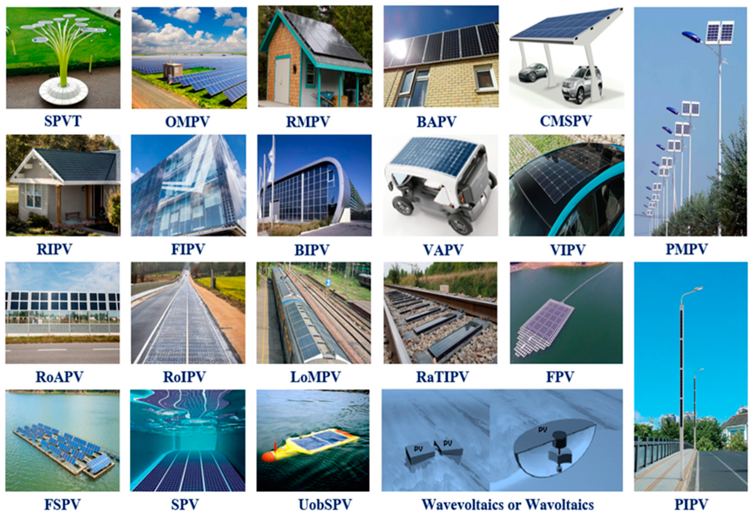
| Photovoltaic Plant Type | Installation Medium | Brief Description | Most Preferred Solar Cell Technology | Land Footprint | Reference |
|---|---|---|---|---|---|
| Solar photovoltaic tree | Land surface and the existing poles or towers | Photovoltaics modules are mounted as leaves on tree-like structures | Crystalline silicon and thin-film solar cells | Very minimum land footprint | [18,19] |
| Open mount | Land surface | Photovoltaics modules are installed on iron mounting structures that are laid on the ground surface with concrete support | Mono and polycrystalline silicon | Very high land footprint and depends on the plant capacity | [3] |
| Roof mount | Building outer peripherals | In roof-mount, building-attached, and canopy-mount solar PV, the photovoltaic modules are attached to the building’s outer peripherals using a rail-less or railed support structure (e.g., windows, roofs, façades, etc.) | No direct land footprint but there exists indirect land footprint | [3,4] | |
| Building attached | [8] | ||||
| Canopy-mount solar | Crystalline silicon, amorphous silicon, thin films like CdTe, CIGS, and flexible solar cells | [9] | |||
| Roof integrated | In roof-integrated, façade-integrated, and building-integrated PV, the photovoltaic modules are integrated into the outer building peripherals by replacing the building structures, such as windows, roofs, façades, etc. | [5] | |||
| Façade integrated | [6] | ||||
| Building integrated | [20] | ||||
| Vehicle integrated or vehicle mount | Vehicle outer peripherals | Photovoltaics modules are installed or integrated into vehicle structures such as window glass, sunroof, etc. | [10] | ||
| Road and rail integrated | On-road and rail track infrastructure | Photovoltaics modules are integrated into the road, rail tracks, and other infrastructure | Crystalline silicon, amorphous silicon, thin-film, and flexible solar cells | [11] | |
| Pole mounted and integrated | Outer peripherals of the street poles | Photovoltaics modules are attached or integrated to the poles, e.g., streetlights | [12] | ||
| Floating solar or Floatovoltaics | Surface of the water body | Photovoltaics modules are mounted onto the floating structures. | Dual glass solar cells | [21] | |
| Underwater on-board solar | Underwater at varying depths of water | Photovoltaics modules are mounted or integrated onto the robot structures or underwater infrastructure peripherals | Crystalline silicon, thin-film, and flexible solar cells | [22] | |
| Submerged | [14] | ||||
| Wavevoltaics | Surface of the wave energy device or any floating buoy | Photovoltaics modules are mounted onto the wave energy devices like a buoy | Thin-film and other flexible solar cells | [23] |
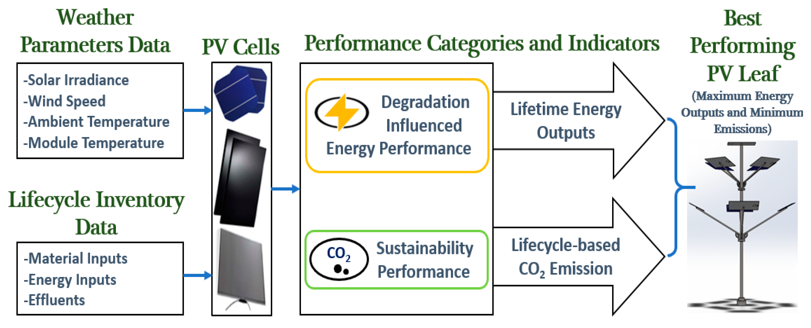
- A framework with a performance prioritization approach (PPA) is proposed to report the performance of a multilayered SPVT intending to select an efficient PV leaf design.
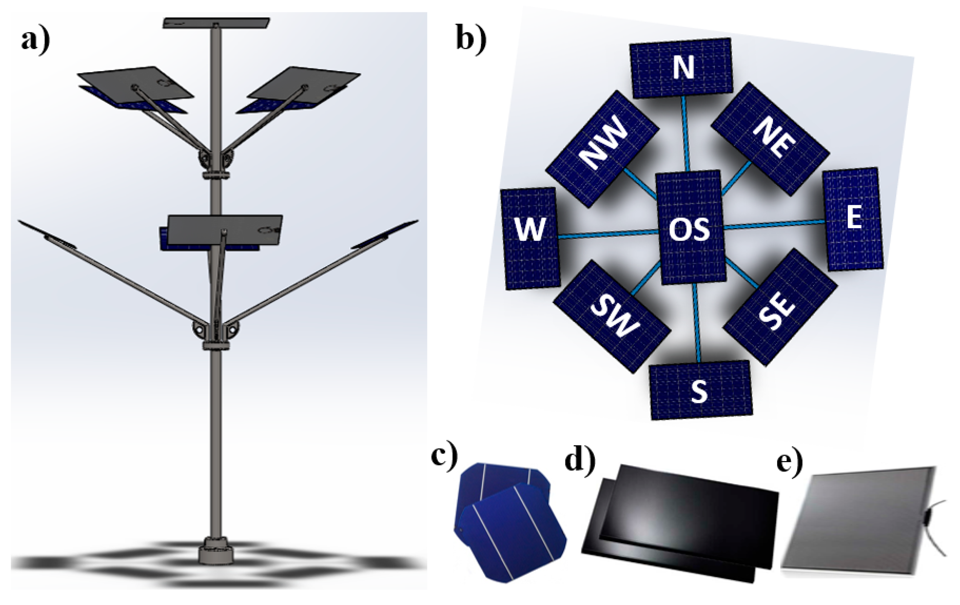
- A three-layered SPVT (3-L SPVT) that has nine leaves—where the upper layer has only one solar PV leaf, the middle and bottom layers have four solar PV leaves each—is simulated, and lifetime energy performance is evaluated for three different PV cell technologies, namely crystalline silicon (c-Si), copper indium gallium selenide (CIGS), and cadmium telluride (CdTe). While evaluating the 3-L SPVT’s performance, power conversion efficiency, thermal regulation, and degradation rate are considered.
- An analysis of the investigated results is carried out, and at the same time the best performing solar PV leaf for a three-layered SPVT is identified among the c-Si, CIGS, and CdTe PV technologies.
2. Description of the Proposed Three-Layered Solar Photovoltaic Tree
3. Solar Photovoltaic Tree Performance Modelling
3.1. Modeling of the Solar Photovoltaics Tree Energy Output
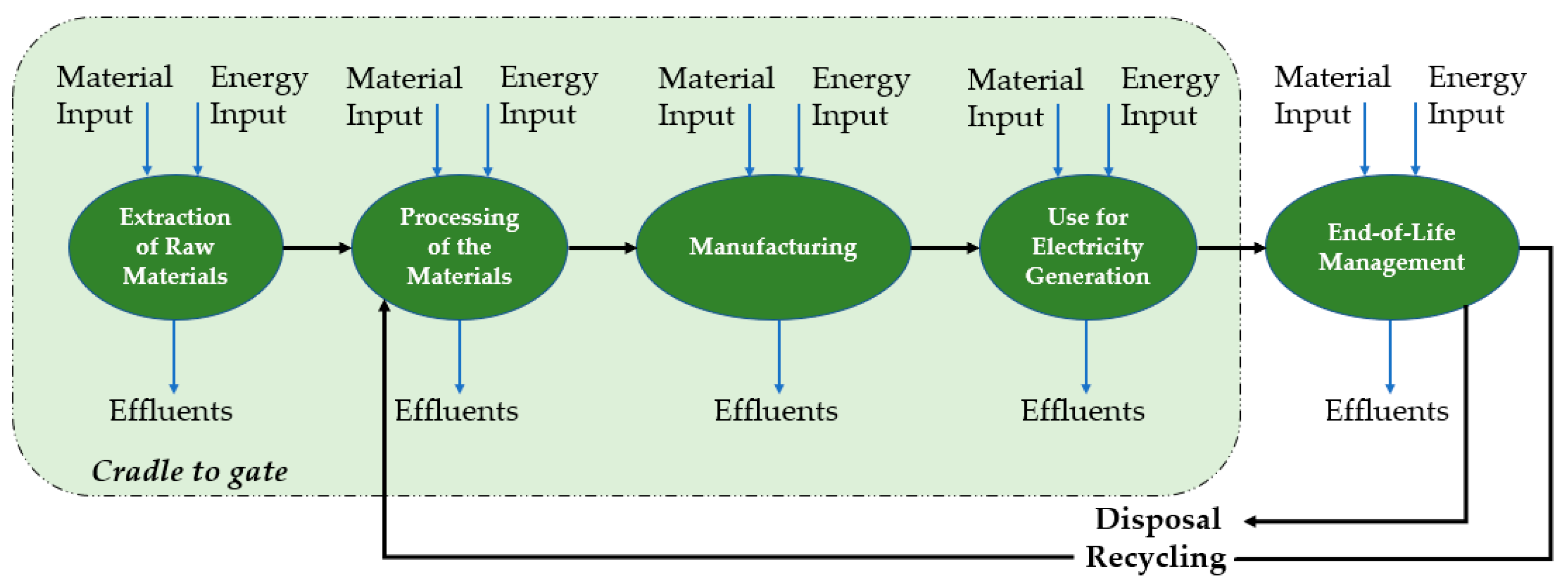
3.2. Modeling of the Solar Photovoltaics Tree Lifecycle Emissions
4. Performance Prioritization Approach Based on Energy and Sustainability Indicators
5. Results and Discussion
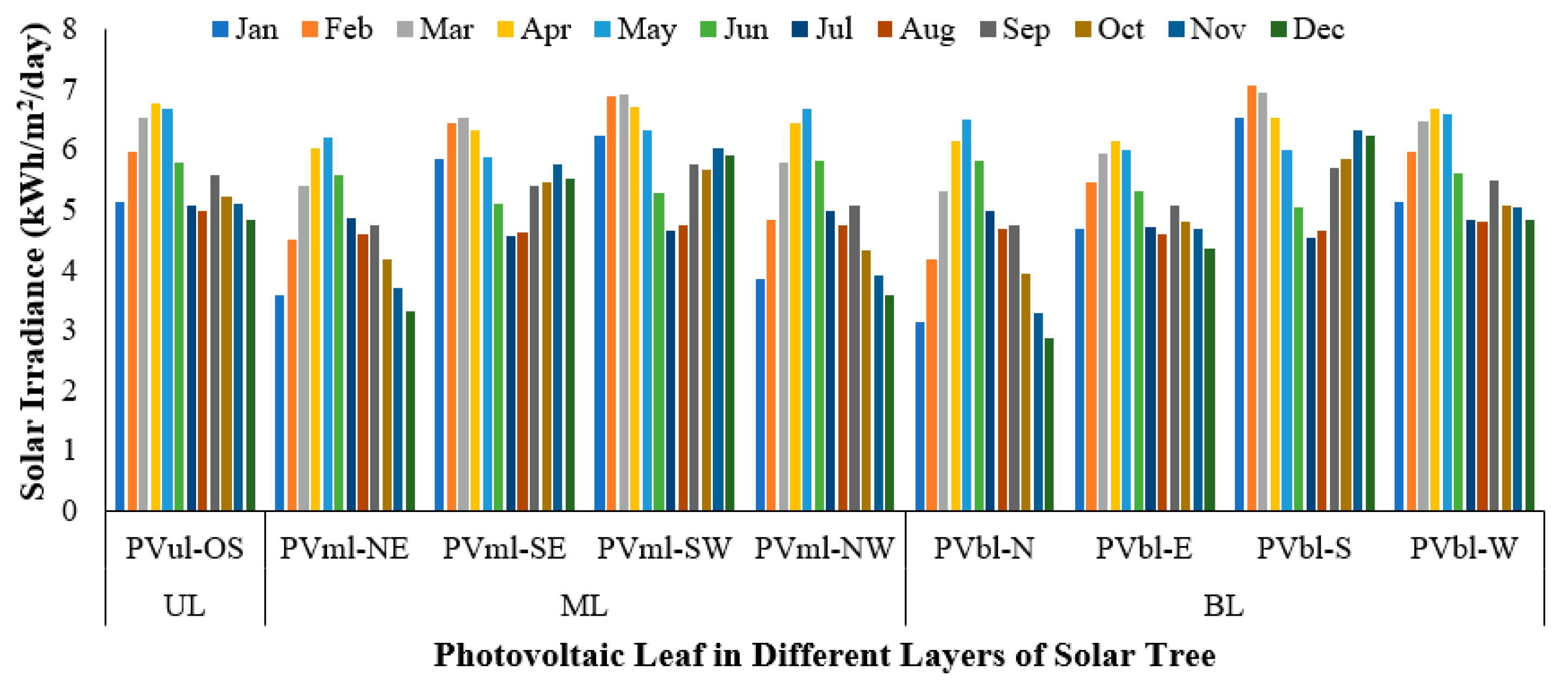
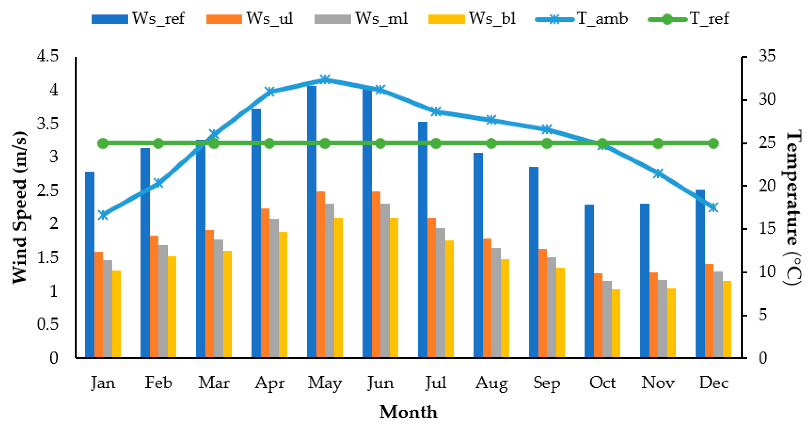
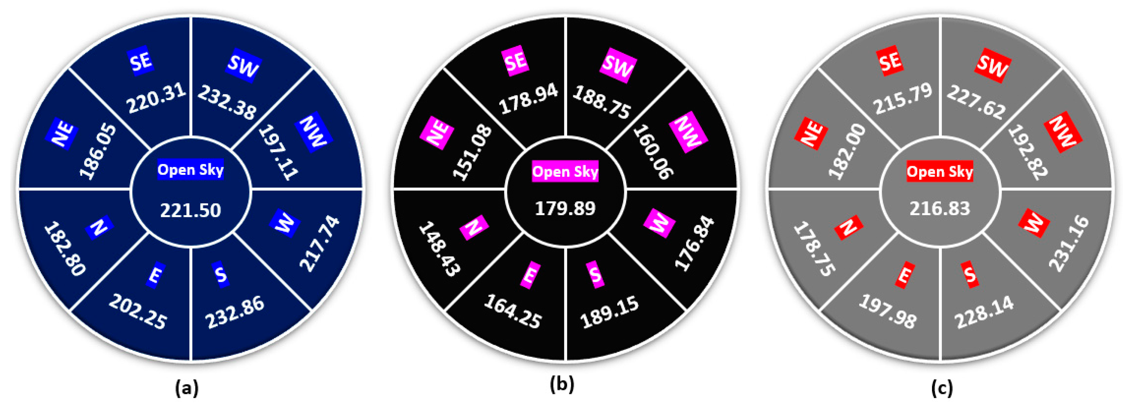
5.1. Analysis of the Weather Parameters
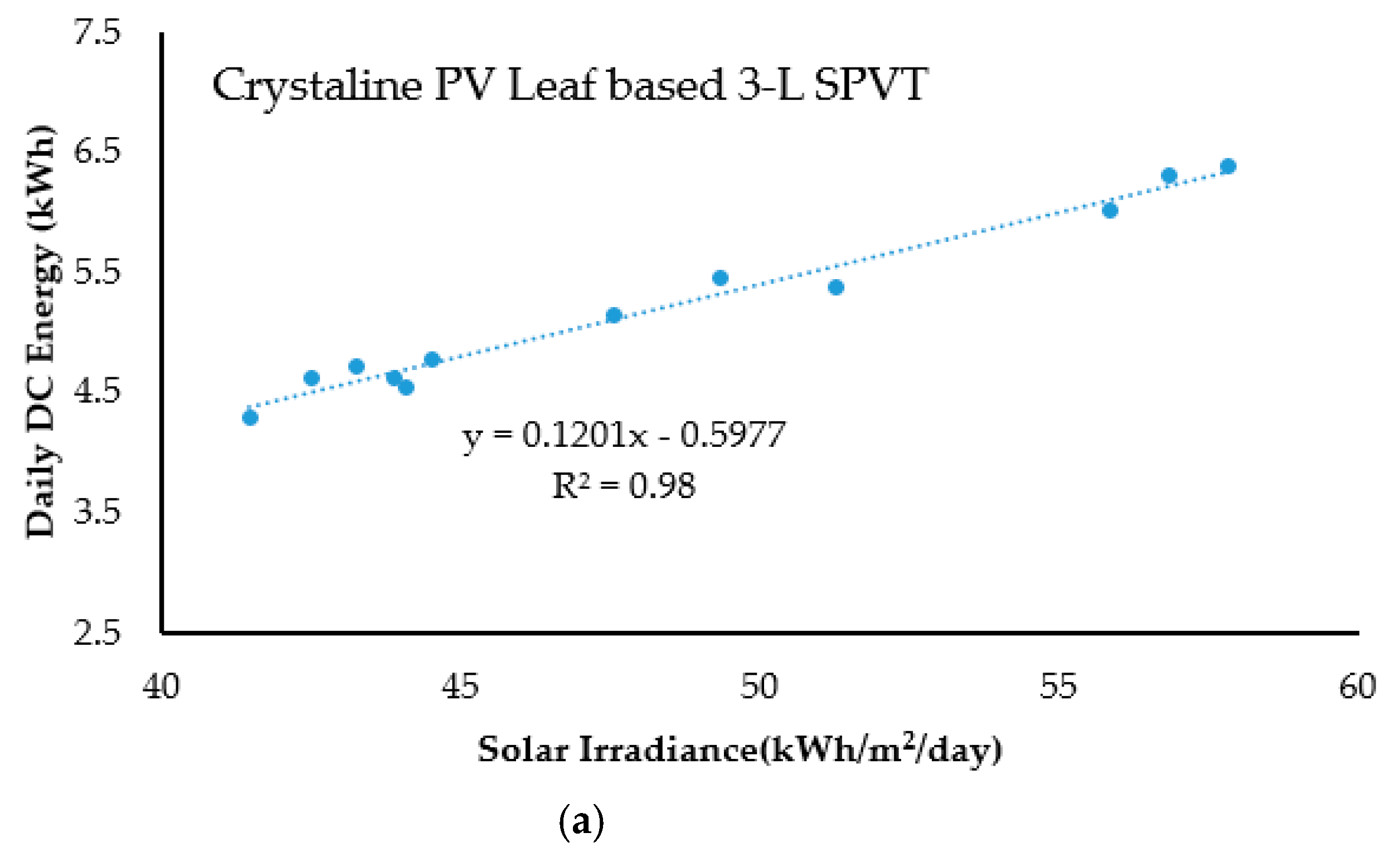
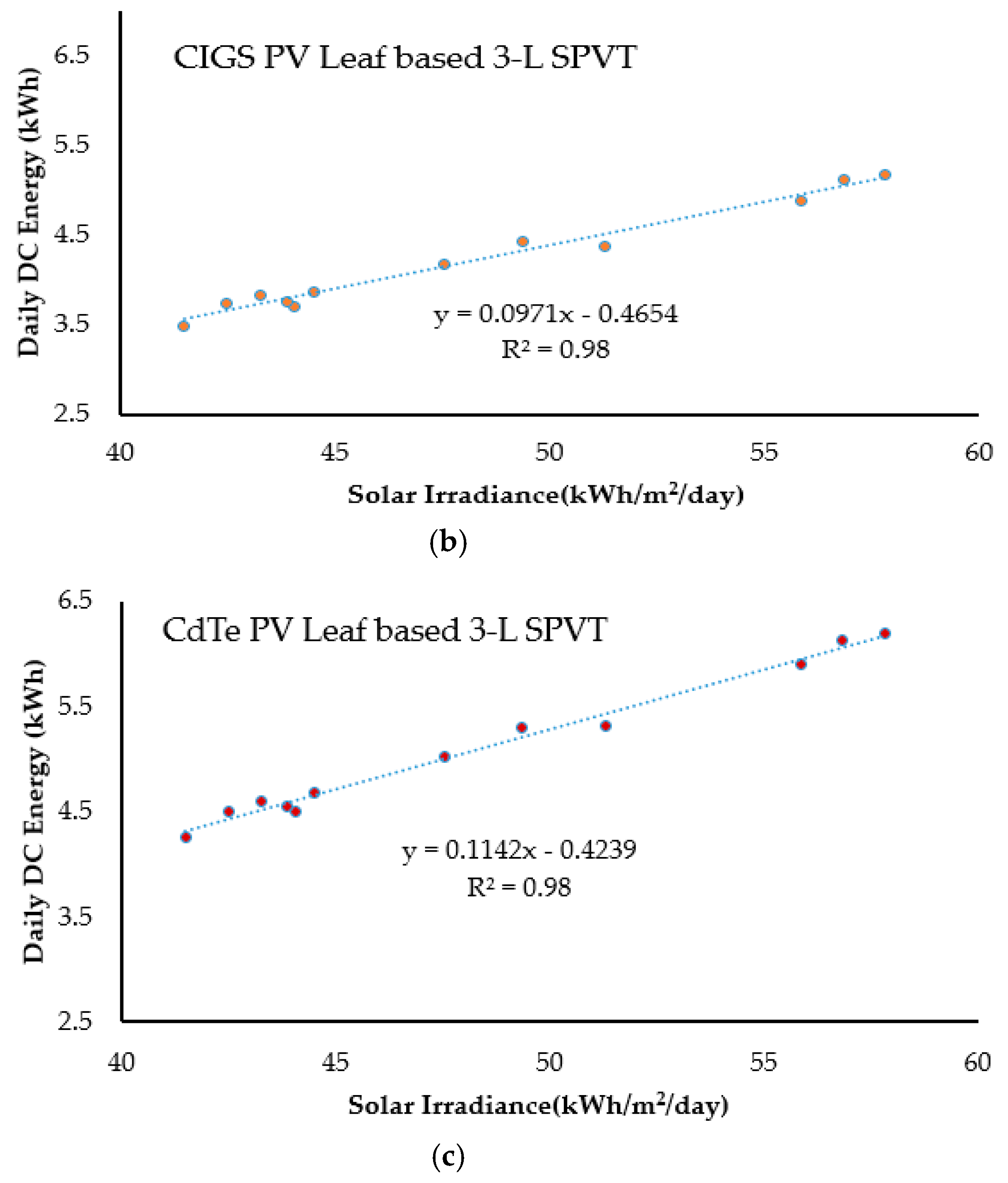
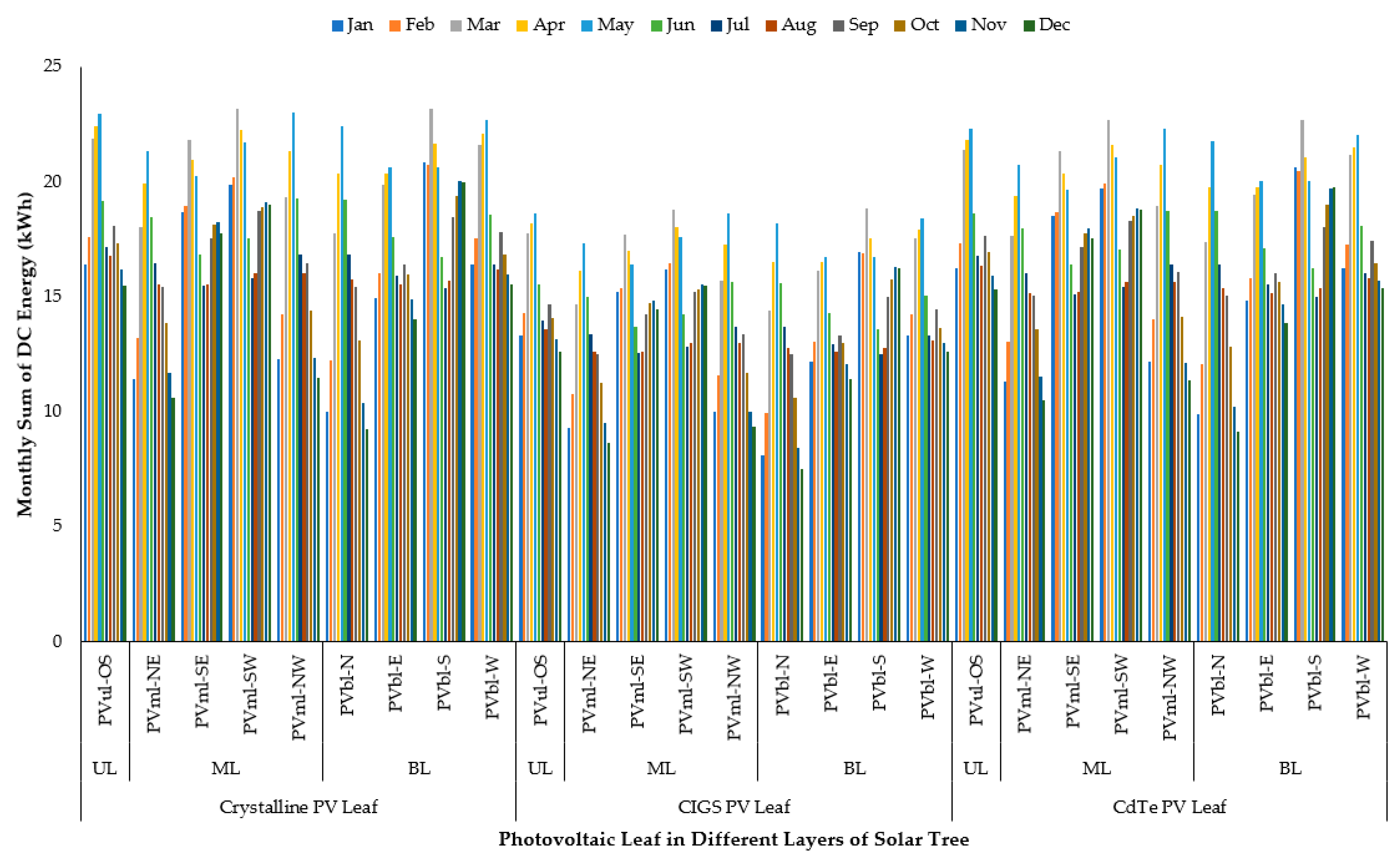
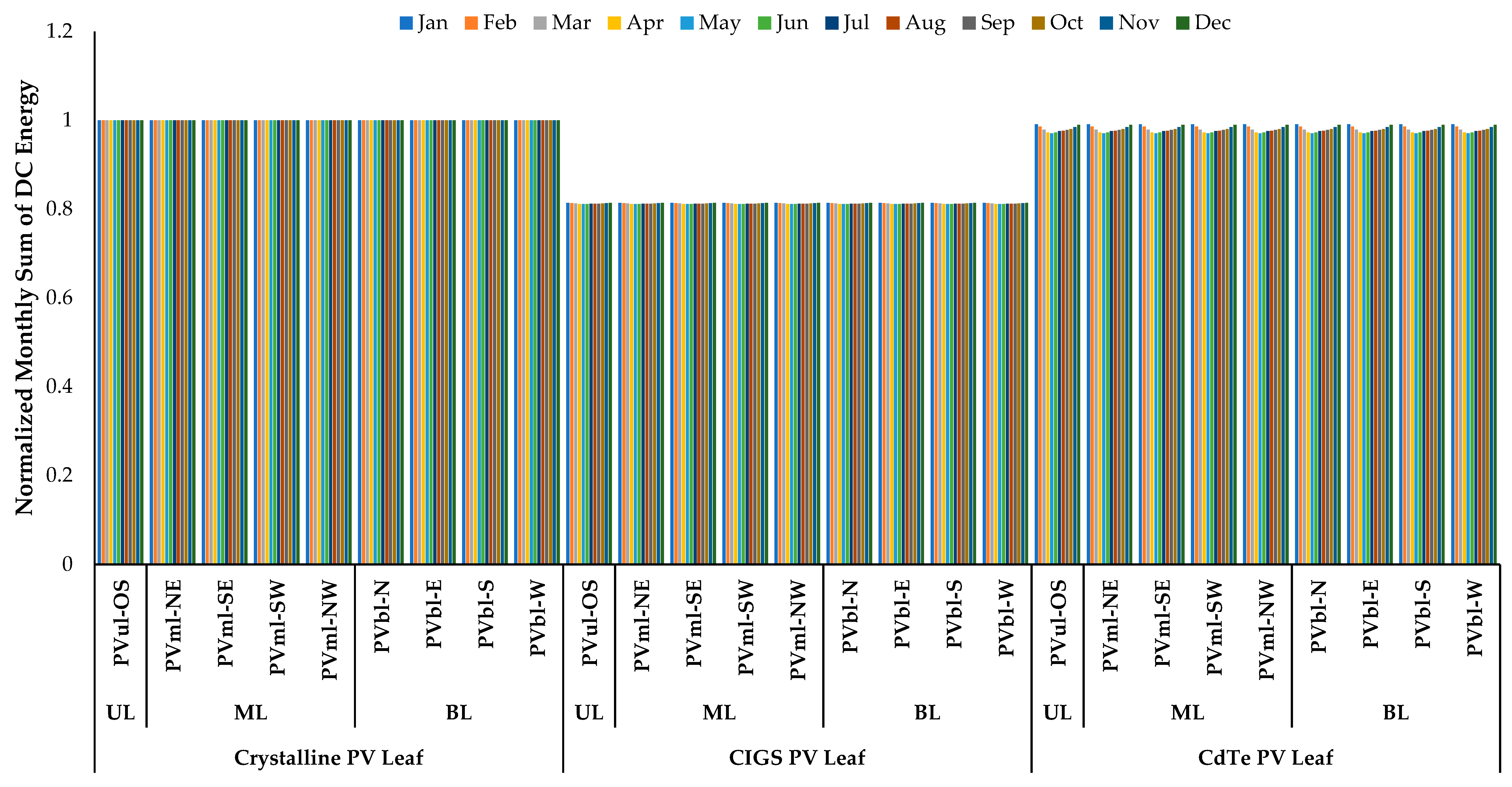
5.2. Energy Analysis
5.2.1. Effect of Orientation, Layered Structure, and Solar Cell Technology Annual Energy Outputs
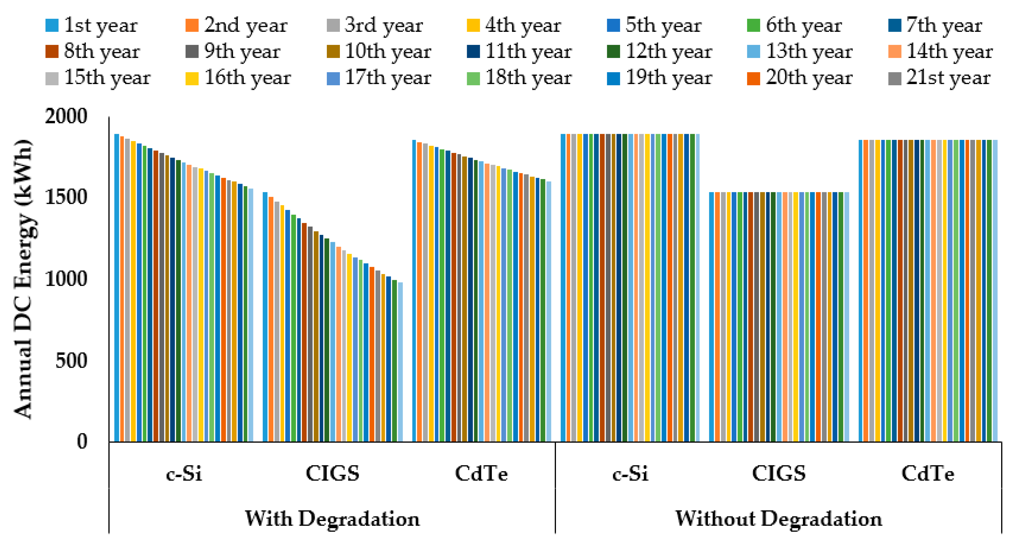
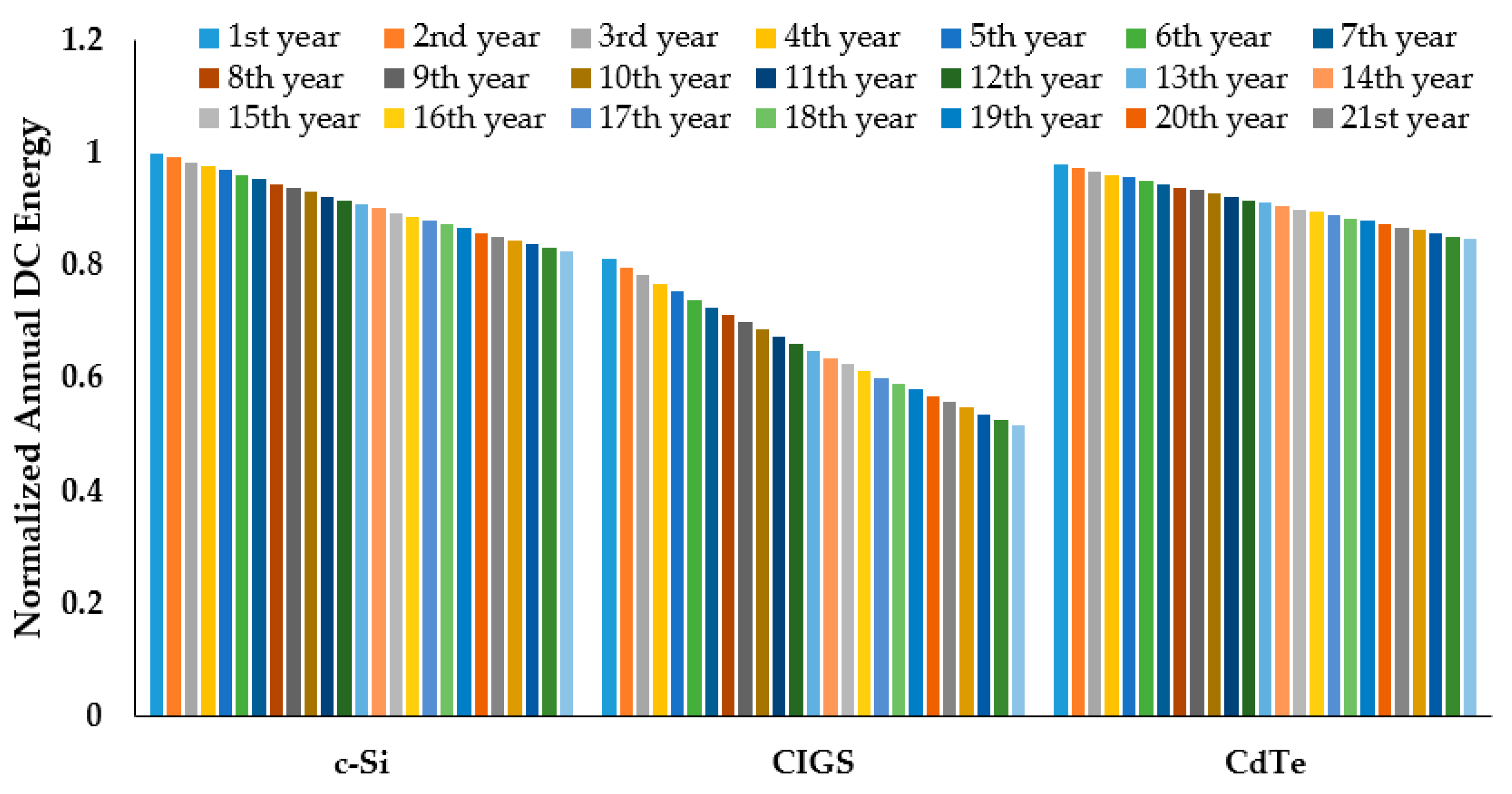
5.2.2. Effect of Degradation Rates on the PV Leaf Annual Energy Outputs
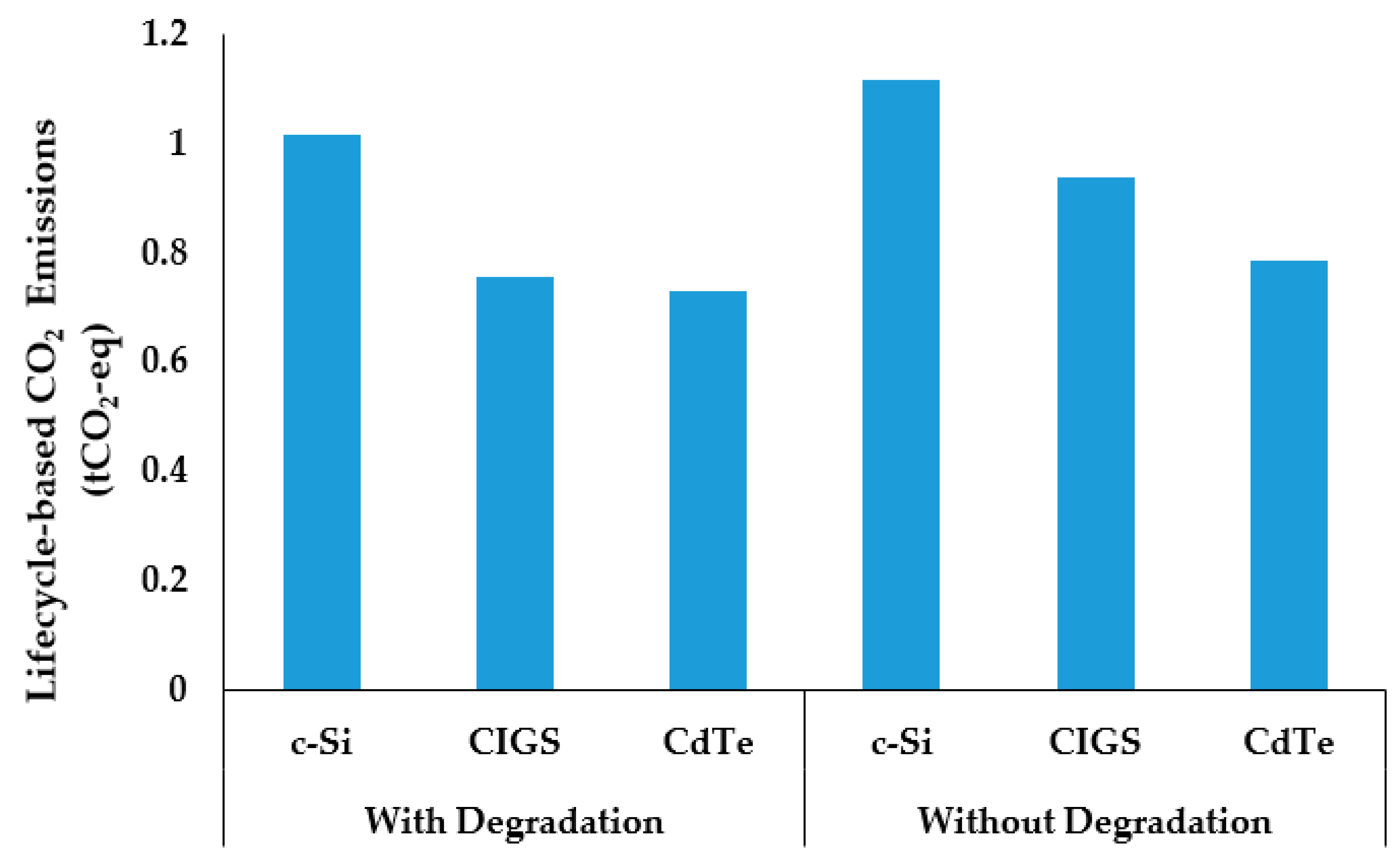
5.3. Emissions Analysis
5.4. Selection of Solar Cell Technologies for SPVTs Based on Energy and Sustainability Indicators
6. Conclusions and Future Research Scope
- c-Si PV cells perform better when all the factors that affect performance are taken into account; however, this is found to be true for only a few years.
- When the DR is considered, the CdTe cells are observed to perform better for SPVT applications due to its lower degradation rates.
- It was observed that the PV cell degradation rate plays a crucial role in identifying the best performing PV technology for SPVTs.
- The CdTe solar PV leaves produced lower CO2 emissions when compared to the other two.
- In addition, the benefits associated with CdTe cells, such as a flexible structure, a ultrathin glass structure, and low-cost manufacturing, make them the best acceptable PV leaves for a SPVT design.
Author Contributions
Funding
Conflicts of Interest
Appendix A
| Algorithm A1: Algorithm for evaluating the energy and sustainability indicators |
| Start // Reading the data related to energy indicators = csv.Read(AnnualEnergyOutputs)//read annual energy outputs in kWh = csv.Read(DegradationRate)//read performance degradation in % = 25//lifetime of the solar photovoltaics tree in years // Computing degradation influenced lifetime energy outputs using Equations (8) and (9) = csv.Compute(EffectiveAESPVT)/compute effective annual energy outputs in kWh = 25//lifetime of the solar photovoltaics tree in years = csv.Compute(LifetimeEnergyOuputs)//compute lifetime energy outputs in kWh // Reading the GHG emission data related to cradle to gate sustainability indicators GHG = csv.Read(GHGEmissonsPerUnitElectrictiyProduction)//read GHG emission per electricity production in gCO2-eq/kWh = 25//lifetime of the solar photovoltaics tree in years // Computing lifecycle-based CO2 emissions = csv.Compute(Lifecycle-basedCO2Emission)//compute lifecycle-based CO2 emission in tCO2 End |
| Algorithm A2: Algorithm for selecting the solar cell technology that produces maximum lifetime energy |
| Start // Conditions for selecting the maximum lifetime energy outputs a = //lifetime energy outputs of 3-L SPVT using c-Si solar cell technology in kWh b = //lifetime energy outputs of 3-L SPVT using CIGS solar cell technology in kWh c = //lifetime energy outputs of 3-L SPVT using CdTe solar cell technology in kWh if a>b & & a>c disp(a)//display 3-L SPVT using c-Si solar cell technology produces maximum energy outputs elseif b>a && b>c disp(b)//display 3-L SPVT using CIGS solar cell technology produces maximum energy outputs else disp(c)//display 3-L SPVT using CdTe solar cell technology produces maximum energy outputs end End |
| Algorithm A3: Algorithm for selecting the solar cell technology that produces minimum lifecycle emission |
| Start // Conditions for selecting the minimum lifecycle emission d = //lifecycle-based CO2 emission of 3-L SPVT using c-Si solar cell technology in kWh e = //lifecycle-based CO2 emission of 3-L SPVT using CIGS solar cell technology in kWh f = //lifecycle-based CO2 emission of 3-L SPVT using CdTe solar cell technology in kWh if d<e & & d<f disp(d)//display 3-L SPVT using c-Si solar cell technology produces minimum CO2 emission elseif e<d && e<f disp(e)//display 3-L SPVT using CIGS solar cell technology produces minimum CO2 emission else disp(f)//display 3-L SPVT using CdTe solar cell technology produces minimum CO2 emission end End |
References
- SDG Compass. SDG 7: Ensure Access to Affordable, Reliable, Sustainable and Modern Energy for All. Available online: https://sdgcompass.org/wp-content/uploads/2016/04/Goal_7.pdf (accessed on 2 September 2020).
- Kumar, N.M.; Chopra, S.S.; Chand, A.A.; Elavarasan, R.M.; Shafiullah, G.M. Hybrid renewable energy microgrid for a residential community: A techno-economic and environmental perspective in the context of the SDG7. Sustainability 2020, 12, 3944. [Google Scholar] [CrossRef]
- Aghaei, M.; Kumar, N.M.; Eskandari, A.; Ahmed, H.; de Oliveira, A.K.V.; Chopra, S.S. Solar PV systems design and monitoring. In Photovoltaic Solar Energy Conversion; Academic Press: Cambridge, MA, USA, 2020; pp. 117–145. [Google Scholar]
- Kumar, N.M.; Reddy, P.R.K.; Praveen, K. Optimal energy performance and comparison of open rack and roof mount mono c-Si photovoltaic Systems. Energy Procedia 2017, 117, 136–144. [Google Scholar] [CrossRef]
- Kumar, N.M.; Yadav, S.K.; Chopra, S.S.; Bajpai, U.; Gupta, R.P.; Padmanaban, S.; Blaabjerg, F. Operational performance of on-grid solar photovoltaic system integrated into pre-fabricated portable cabin buildings in warm and temperate climates. Energy Sustain. Dev. 2020, 57, 109–118. [Google Scholar] [CrossRef]
- Attoye, D.E.; Tabet Aoul, K.A.; Hassan, A. A review on building integrated photovoltaic façade customization potentials. Sustainability 2017, 9, 2287. [Google Scholar] [CrossRef] [Green Version]
- Reddy, P.; Gupta, M.V.N.; Nundy, S.; Karthick, A.; Ghosh, A. Status of BIPV and BAPV System for Less Energy-Hungry Building in India—A Review. Appl. Sci. 2020, 10, 2337. [Google Scholar] [CrossRef] [Green Version]
- Kumar, N.M.; Sudhakar, K.; Samykano, M. Performance comparison of BAPV and BIPV systems with c-Si, CIS and CdTe photovoltaic technologies under tropical weather conditions. Case Stud. Therm. Eng. 2019, 13, 100374. [Google Scholar] [CrossRef]
- Alghamdi, A.S.; Bahaj, A.S.; Wu, Y. Assessment of large scale photovoltaic power generation from carport canopies. Energies 2017, 10, 686. [Google Scholar] [CrossRef] [Green Version]
- Araki, K.; Ota, Y.; Yamaguchi, M. Measurement and modeling of 3D solar irradiance for vehicle-integrated photovoltaic. Appl. Sci. 2020, 10, 872. [Google Scholar] [CrossRef] [Green Version]
- Northmore, A.; Tighe, S. Innovative pavement design: Are solar roads feasible. In Conference & Exhibition of the Transportation Association of Canada (TAC); Transportation Association of Canada: Ottawa, ON, Canada, 2012. [Google Scholar]
- Asanov, I.M.; Loktionov, E.Y. Possible benefits from PV modules integration in railroad linear structures. Renew. Energy Focus 2018, 25, 1–3. [Google Scholar] [CrossRef]
- Amber, K.P.; Hussain, I.; Kousar, A.; Bashir, M.A.; Aslam, M.W.; Akbar, B. A self-cleaning device for pole mounted solar photovoltaic installations. Therm. Sci. 2019, 23 Pt A, 739–749. [Google Scholar]
- Kumar, N.M.; Subramaniam, U.; Mathew, M.; Ajitha, A.; Almakhles, D.J. Exergy analysis of thin-film solar PV module in ground-mount, floating and submerged installation methods. Case Stud. Therm. Eng. 2020, 21, 100686. [Google Scholar] [CrossRef]
- Ajitha, A.; Kumar, N.M.; Jiang, X.X.; Reddy, G.R.; Jayakumar, A.; Praveen, K.; Kumar, T.A. Underwater performance of thin-film photovoltaic module immersed in shallow and deep waters along with possible applications. Results Phys. 2019, 15, 102768. [Google Scholar] [CrossRef]
- Kumar, N.M. Model to estimate the potential and performance of wavevoltaics. Results Phys. 2019, 12, 914–916. [Google Scholar] [CrossRef]
- Gangwar, P.; Kumar, N.M.; Singh, A.K.; Jayakumar, A.; Mathew, M. Solar photovoltaic tree and its end-of-life management using thermal and chemical treatments for material recovery. Case Stud. Therm. Eng. 2019, 14, 100474. [Google Scholar] [CrossRef]
- Gangwar, P.; Singh, R.; Tripathi, R.P.; Singh, A.K. Effective solar power harnessing using a few novel solar tree designs and their performance assessment. Energy Sources Part A Recovery Util. Environ. Eff. 2019, 41, 1828–1837. [Google Scholar] [CrossRef]
- Hyder, F.; Baredar, P.; Sudhakar, K.; Mamat, R. Performance and land footprint analysis of a solar photovoltaic tree. J. Clean. Prod. 2018, 187, 432–448. [Google Scholar] [CrossRef]
- Gholami, H.; Røstvik, H.N.; Kumar, N.M.; Chopra, S.S. Lifecycle cost analysis (LCCA) of tailor-made building integrated photovoltaics (BIPV) façade: Solsmaragden case study in Norway. Sol. Energy 2020, 211, 488–502. [Google Scholar] [CrossRef]
- Kumar, N.M.; Kanchikere, J.; Mallikarjun, P. Floatovoltaics: Towards improved energy efficiency, land and water management. Int. J. Civ. Eng. Technol. 2018, 9, 1089–1096. [Google Scholar]
- García-Córdova, F.; Guerrero-González, A. Intelligent navigation for a solar powered unmanned underwater vehicle. Int. J. Adv. Robot. Syst. 2013, 10, 185. [Google Scholar] [CrossRef] [Green Version]
- Manoj Kumar, N. Wavevoltaics: A new hybrid wave photon energy device. Curr. Sci. 2018, 115, 1251. [Google Scholar]
- Hyder, F.; Sudhakar, K.; Mamat, R. Solar PV tree design: A REVIEW. Renew. Sustain. Energy Rev. 2018, 82, 1079–1096. [Google Scholar] [CrossRef]
- Khan, H.; Gaur, P. Design of solar tree with photovoltaic panels using Fibonacci pattern. Adv. Res. Electr. Electron. Eng. 2015, 2, 67–71. [Google Scholar]
- Maity, S.N. Development of solar power tree–an innovation that uses up very less land and yet generates much more energy from the sun rays by SPV method. J. Environ. Nanotechnol. 2013, 2, 59–69. [Google Scholar] [CrossRef]
- Avdić, V.; Zečević, S.; Pervan, N.; Tasić, P.; Muminović, A.J. Different Design Solutions of Solar Trees in Urban Environment; University of Sarajevo: Sarajevo, Bosnia and Herzegovina, 2013; Volume 2, pp. 1–4. [Google Scholar]
- Cao, W.; Li, Z.; Yang, Y.; Zheng, Y.; Yu, W.; Afzal, R.; Xue, J. “Solar tree”: Exploring new form factors of organic solar cells. Renew. Energy 2014, 72, 134–139. [Google Scholar] [CrossRef]
- Association ECOPOWER Solar Tree. Available online: http://www.association-ecopower.com/eco-marketing.html (accessed on 2 September 2020).
- Manoj Kumar, N.; Ghosh, A.; Chopra, S.S. Power resilience enhancement of a residential electricity user using photovoltaics and a battery energy storage system under uncertainty conditions. Energies 2020, 13, 4193. [Google Scholar] [CrossRef]
- Tata Solar Power Modules. Available online: https://www.tatapowersolar.com/ (accessed on 13 August 2020).
- First Solar PV Module. Available online: http://www.firstsolar.com/Modules/Series-6 (accessed on 2 September 2020).
- Nice Solar Energy. Available online: https://nice-solarenergy.com/en/cigs-modules.html (accessed on 2 September 2020).
- India Meteorological Department (IMD), Ministry of Earth Sciences, Government of India (GoI). Available online: https://mausam.imd.gov.in/ (accessed on 10 August 2019).
- Faiman, D. Assessing the outdoor operating temperature of photovoltaic modules. Prog. Photovolt. Res. Appl. 2008, 16, 307–315. [Google Scholar] [CrossRef]
- Gökmen, N.H.; Hu, W.; Hou, P.; Chen, Z.; Sera, D.; Spataru, S. Investigation of wind speed cooling effect on PV panels in windy locations. Renew. Energy 2016, 90, 283–290. [Google Scholar] [CrossRef]
- Kumar, N.M.; Prabaharan, N.; Jerin, R.A.; Jayakumar, A. Impact of performance degradation and capital subsidy on the revenue of rooftop PV system. Int. J. Renew. Energy Res. 2019, 9, 128–136. [Google Scholar]
- Ascencio-Vásquez, J.; Kaaya, I.; Brecl, K.; Weiss, K.-A.; Topič, M. Global Climate Data Processing and Mapping of Degradation Mechanisms and Degradation Rates of PV Modules. Energies 2019, 12, 4749. [Google Scholar] [CrossRef] [Green Version]
- Dubey, R.; Chattopadhyay, S.; Kuthanazhi, V.; Kottantharayil, A.; Singh Solanki, C.; Arora, B.M.; Narasimhan, K.L.; Vasi, J.; Bora, B.; Singh, Y.K.; et al. Comprehensive study of performance degradation of field-mounted photovoltaic modules in India. Energy Sci. Eng. 2017, 5, 51–64. [Google Scholar] [CrossRef]
- Rajput, P.; Malvoni, M.; Manoj Kumar, N.; Sastry, O.S.; Jayakumar, A. Operational performance and degradation influenced life cycle environmental–economic metrics of mc-Si, a-Si and HIT photovoltaic Arrays in hot semi-arid climates. Sustainability 2020, 12, 1075. [Google Scholar] [CrossRef] [Green Version]
- Peng, J.; Lu, L.; Yang, H. Review on life cycle assessment of energy payback and greenhouse gas emission of solar photovoltaic systems. Renew. Sustain. Energy Rev. 2013, 19, 255–274. [Google Scholar] [CrossRef]
- Frischknecht, R.; Itten, R.; Sinha, P.; de Wild-Scholten, M.; Zhang, J.; Fthenakis, V.; Kim, H.C.; Raugei, M.; Stucki, M. Life Cycle Inventories and Life Cycle Assessments of Photovoltaic Systems (No. NREL/TP-6A20-73853); Report T12-04; National Renewable Energy Lab: Golden, CO, USA, 2015. [Google Scholar]
- Rajput, P.; Malvoni, M.; Kumar, N.M.; Sastry, O.S.; Tiwari, G.N. Risk priority number for understanding the severity of photovoltaic failure modes and their impacts on performance degradation. Case Stud. Therm. Eng. 2019, 16, 100563. [Google Scholar] [CrossRef]
- Jordan, D.C.; Deline, C.; Deceglie, M.G.; Nag, A.; Kimball, G.M.; Shinn, A.B.; John, J.J.; Alnuaimi, A.A.; Elnosh, A.B.A.; Luo, W.; et al. Reducing Interanalyst variability in photovoltaic degradation rate assessments. IEEE J. Photovolt. 2020, 10, 206–212. [Google Scholar] [CrossRef]
- Jordan, D.C.; Kurtz, S.R.; VanSant, K.; Newmiller, J. Compendium of photovoltaic degradation rates. Prog. Photovolt. Res. Appl. 2016, 24, 978–989. [Google Scholar] [CrossRef]
- Phinikarides, A.; Kindyni, N.; Makrides, G.; Georghiou, G.E. Review of photovoltaic degradation rate methodologies. Renew. Sustain. Energy Rev. 2014, 40, 143–152. [Google Scholar] [CrossRef]
- Jordan, D.C.; Kurtz, S.R. Photovoltaic degradation rates—An analytical review. Prog. Photovolt. Res. Appl. 2013, 21, 12–29. [Google Scholar] [CrossRef] [Green Version]
- De Wild-Scholten, M.M. Energy payback time and carbon footprint of commercial photovoltaic systems. Sol. Energy Mater. Sol. Cells 2013, 119, 296–305. [Google Scholar] [CrossRef]


| Solar Tree | PV Leaf Layer | Number of PV Leaves in a Layer | PV Leaf | Orientation | Tilt Angle (°) |
|---|---|---|---|---|---|
| Three-layer design | Upper layer | 1 | PVul-OS | Open sky | 0 |
| Middle layer | 4 | PVml-NE | Northeast | 25.4358 | |
| PVml-SE | Southeast | ||||
| PVml-SW | Southwest | ||||
| PVml-NW | Northwest | ||||
| Bottom layer | 4 | PVbl-N | North | 25.4358 | |
| PVbl-E | East | ||||
| PVbl-S | South | ||||
| PVbl-W | West |
| Solar Cell Technology | Efficiency (%) | Area (m2) | Temperature Coefficient (%/°C) |
|---|---|---|---|
| Crystalline silicon (c-Si) | 14.90 | 0.72 | −0.47 |
| Copper indium gallium selenide (CIGS) | 12.10 | −0.45 | |
| Cadmium telluride (CdTe) | 14.60 | −0.34 |
| Solar Cell Technology | Faiman Coefficients for Different Solar Cell Technologies | |
|---|---|---|
| Crystalline silicon (c-Si) | 30.02 | 6.28 |
| Copper indium gallium selenide (CIGS) | 22.19 | 4.09 |
| Cadmium telluride (CdTe) | 23.37 | 5.44 |
| Month | Monthly Average of Daily Energy Outputs of C-Si Photovoltaic Leaf (kWh) | ||||||||
|---|---|---|---|---|---|---|---|---|---|
| Upper Layer | Middle Layer | Bottom Layer | |||||||
| Pul-OS | Pml-NE | Pml-SE | Pml-SW | Pml-NW | Pbl-N | Pbl-E | Pbl-S | Pbl-W | |
| January | 0.53 | 0.37 | 0.60 | 0.64 | 0.40 | 0.32 | 0.48 | 0.67 | 0.53 |
| February | 0.63 | 0.47 | 0.68 | 0.72 | 0.50 | 0.44 | 0.57 | 0.74 | 0.63 |
| March | 0.71 | 0.58 | 0.70 | 0.75 | 0.62 | 0.57 | 0.64 | 0.75 | 0.69 |
| April | 0.75 | 0.66 | 0.69 | 0.74 | 0.71 | 0.68 | 0.68 | 0.72 | 0.74 |
| May | 0.74 | 0.69 | 0.65 | 0.70 | 0.74 | 0.72 | 0.66 | 0.67 | 0.73 |
| June | 0.64 | 0.62 | 0.56 | 0.58 | 0.64 | 0.64 | 0.59 | 0.56 | 0.62 |
| July | 0.55 | 0.53 | 0.50 | 0.51 | 0.54 | 0.54 | 0.51 | 0.49 | 0.53 |
| August | 0.54 | 0.50 | 0.50 | 0.52 | 0.52 | 0.51 | 0.50 | 0.51 | 0.52 |
| September | 0.60 | 0.51 | 0.59 | 0.62 | 0.55 | 0.51 | 0.55 | 0.61 | 0.59 |
| October | 0.56 | 0.45 | 0.59 | 0.61 | 0.46 | 0.42 | 0.51 | 0.62 | 0.54 |
| November | 0.54 | 0.39 | 0.61 | 0.64 | 0.41 | 0.34 | 0.49 | 0.67 | 0.53 |
| December | 0.50 | 0.34 | 0.57 | 0.61 | 0.37 | 0.29 | 0.45 | 0.64 | 0.50 |
| Month | Monthly Average of Daily Energy Outputs of CIGS Photovoltaic Leaf (kWh) | ||||||||
|---|---|---|---|---|---|---|---|---|---|
| Upper Layer | Middle Layer | Bottom Layer | |||||||
| Pul-OS | Pml-NE | Pml-SE | Pml-SW | Pml-NW | Pbl-N | Pbl-E | Pbl-S | Pbl-W | |
| January | 0.43 | 0.30 | 0.49 | 0.52 | 0.32 | 0.26 | 0.39 | 0.55 | 0.43 |
| February | 0.51 | 0.38 | 0.55 | 0.59 | 0.41 | 0.36 | 0.47 | 0.60 | 0.51 |
| March | 0.57 | 0.47 | 0.57 | 0.61 | 0.51 | 0.47 | 0.52 | 0.61 | 0.57 |
| April | 0.61 | 0.54 | 0.57 | 0.60 | 0.58 | 0.55 | 0.55 | 0.59 | 0.61 |
| May | 0.60 | 0.56 | 0.53 | 0.57 | 0.60 | 0.59 | 0.54 | 0.54 | 0.60 |
| June | 0.52 | 0.50 | 0.46 | 0.47 | 0.52 | 0.52 | 0.48 | 0.45 | 0.50 |
| July | 0.45 | 0.43 | 0.41 | 0.41 | 0.44 | 0.44 | 0.42 | 0.40 | 0.43 |
| August | 0.44 | 0.41 | 0.41 | 0.42 | 0.42 | 0.41 | 0.41 | 0.41 | 0.42 |
| September | 0.49 | 0.42 | 0.48 | 0.51 | 0.45 | 0.42 | 0.44 | 0.50 | 0.48 |
| October | 0.45 | 0.36 | 0.48 | 0.49 | 0.38 | 0.34 | 0.42 | 0.51 | 0.44 |
| November | 0.44 | 0.32 | 0.50 | 0.52 | 0.33 | 0.28 | 0.40 | 0.54 | 0.43 |
| December | 0.41 | 0.28 | 0.47 | 0.50 | 0.30 | 0.24 | 0.37 | 0.52 | 0.41 |
| Month | Monthly Average of Daily Energy Outputs of Cdte Photovoltaic Leaf (kWh) | ||||||||
|---|---|---|---|---|---|---|---|---|---|
| Upper Layer | Middle Layer | Bottom Layer | |||||||
| Pul-OS | Pml-NE | Pml-SE | Pml-SW | Pml-NW | Pbl-N | Pbl-E | Pbl-S | Pbl-W | |
| January | 0.52 | 0.36 | 0.60 | 0.64 | 0.39 | 0.32 | 0.48 | 0.67 | 0.52 |
| February | 0.62 | 0.47 | 0.67 | 0.71 | 0.50 | 0.43 | 0.56 | 0.73 | 0.62 |
| March | 0.70 | 0.57 | 0.69 | 0.73 | 0.61 | 0.56 | 0.63 | 0.73 | 0.68 |
| April | 0.73 | 0.65 | 0.68 | 0.72 | 0.69 | 0.66 | 0.66 | 0.70 | 0.72 |
| May | 0.72 | 0.67 | 0.63 | 0.68 | 0.72 | 0.70 | 0.65 | 0.65 | 0.71 |
| June | 0.62 | 0.60 | 0.55 | 0.57 | 0.62 | 0.62 | 0.57 | 0.54 | 0.60 |
| July | 0.54 | 0.52 | 0.49 | 0.50 | 0.53 | 0.53 | 0.50 | 0.48 | 0.52 |
| August | 0.53 | 0.49 | 0.49 | 0.52 | 0.51 | 0.50 | 0.49 | 0.50 | 0.51 |
| September | 0.59 | 0.50 | 0.57 | 0.61 | 0.54 | 0.50 | 0.54 | 0.60 | 0.58 |
| October | 0.55 | 0.44 | 0.57 | 0.60 | 0.46 | 0.41 | 0.52 | 0.61 | 0.53 |
| November | 0.53 | 0.38 | 0.60 | 0.63 | 0.41 | 0.34 | 0.49 | 0.66 | 0.52 |
| December | 0.49 | 0.34 | 0.57 | 0.61 | 0.37 | 0.30 | 0.45 | 0.64 | 0.50 |
| Solar Cell Technology | Degradation Rate (%/Year) | Reference |
|---|---|---|
| Crystalline silicon (c-Si) | 0.80 | [45,46,47] |
| Copper indium gallium selenide (CIGS) | 1.86 | |
| Cadmium telluride (CdTe) | 0.60 |
| Solar Cell Technology | Lifetime Energy Outputs (kWh) | |
|---|---|---|
| Without Degradation | With Degradation | |
| Crystalline silicon (c-Si) | 47,325.98 | 43,049.48 |
| Copper indium gallium selenide (CIGS) | 38,435.34 | 30,963.96 |
| Cadmium telluride (CdTe) | 46,328.66 | 43,141.49 |
| Solar Photovoltaic Cell Technology | Lifecycle-Based CO2 Emissions (gCO2-eq/kWh) | Reference |
|---|---|---|
| Solar PV Leaf + Mounting Structure | ||
| Crystalline silicon (c-Si) | 23.64 | [48] |
| Copper indium gallium selenide (CIGS) | 24.47 | |
| Cadmium telluride (CdTe) | 16.94 |
| 3-L SPVT | Degradation-Influenced Lifetime Energy Outputs (kWh) | Lifecycle-Based CO2 Emissions (tCO2-eq) | Rank | ||
|---|---|---|---|---|---|
| Energy | Sustainability | Overall | |||
| c-Si PV leaf | 43,049.48 | 1.12 | 2 | 3 | 2 |
| CIGS PV leaf | 30,963.96 | 0.94 | 3 | 2 | 3 |
| CdTe PV leaf | 43,141.49 | 0.79 | 1 | 1 | 1 |
Publisher’s Note: MDPI stays neutral with regard to jurisdictional claims in published maps and institutional affiliations. |
© 2020 by the authors. Licensee MDPI, Basel, Switzerland. This article is an open access article distributed under the terms and conditions of the Creative Commons Attribution (CC BY) license (http://creativecommons.org/licenses/by/4.0/).
Share and Cite
Kumar, N.M.; Chopra, S.S.; Malvoni, M.; Elavarasan, R.M.; Das, N. Solar Cell Technology Selection for a PV Leaf Based on Energy and Sustainability Indicators—A Case of a Multilayered Solar Photovoltaic Tree. Energies 2020, 13, 6439. https://0-doi-org.brum.beds.ac.uk/10.3390/en13236439
Kumar NM, Chopra SS, Malvoni M, Elavarasan RM, Das N. Solar Cell Technology Selection for a PV Leaf Based on Energy and Sustainability Indicators—A Case of a Multilayered Solar Photovoltaic Tree. Energies. 2020; 13(23):6439. https://0-doi-org.brum.beds.ac.uk/10.3390/en13236439
Chicago/Turabian StyleKumar, Nallapaneni Manoj, Shauhrat S. Chopra, Maria Malvoni, Rajvikram Madurai Elavarasan, and Narottam Das. 2020. "Solar Cell Technology Selection for a PV Leaf Based on Energy and Sustainability Indicators—A Case of a Multilayered Solar Photovoltaic Tree" Energies 13, no. 23: 6439. https://0-doi-org.brum.beds.ac.uk/10.3390/en13236439