Modified Slot Opening for Reducing Shaft-to-Frame Voltage of AC Motors


1
School of Electrical and Computer Engineering, Ulsan National Institute of Science and Technology, Ulsan 44919, Korea
2
Division of Electronics and Electrical Engineering, Dongguk University, Seoul 04620, Korea
*
Author to whom correspondence should be addressed.
Energies 2020, 13(3), 760; https://0-doi-org.brum.beds.ac.uk/10.3390/en13030760
Submission received: 3 January 2020
/
Revised: 5 February 2020
/
Accepted: 6 February 2020
/
Published: 9 February 2020
Abstract
:This paper presents a method to reduce the winding-to-rotor capacitance of electrical machines for the purpose of suppressing shaft-to-frame voltage, which causes reliability issues, such as electromagnetic interference (EMI) and bearing current. The proposed method is based on the modification of slot opening shape of the stator core, including the variation of slot opening width and the use of oblique slot opening. For the verification of the suggested method, six different slot opening shapes, including a reference design, are analyzed and compared using finite element analysis, and the results show that the proposed method can reduce the shaft-to-frame voltage by 98%, compared to the reference design.
1. Introduction
Recent electrical machine drive systems generally include pulse-with-modulation (PWM) inverters. Drive signals of the inverters may have a significant amount of common-mode voltage that can be coupled to various parts of electrical machine systems through parasitic capacitances. These coupled voltages can be the origin of various harmful phenomenons, such as ground current, shaft voltage, and bearing current.
The bearing current can be categorized into circulating current, non-circulating current, and electrostatic discharge machining (EDM) current [1]. The EDM bearing current is a result of partial discharges between the bearing’s inner and outer races by the development of shaft-to-frame voltage above a threshold. Repeated occurrences of the EDM current can significantly degrade the bearing lifetime [2,3,4]. Thus, the shaft-to-frame voltage should be predicted and reduced for more reliable operation of electrical machine drives.
Until now, reported solutions to mitigate the shaft-to-frame voltage include, for example, inserting electro-static shields between the windings and the rotor, using common-mode filters, modifying the modulation schemes of inverter control signals, and electrically shorting the shaft and the frame of machines [5,6,7].
Nevertheless, the reported solutions cannot handle parasitic capacitances themselves that are root causes of the undesired voltages. By dealing with the capacitances, it is expected that we can effectively reduce the voltage without using any extra devices or modifications. For the purpose, this paper proposes a method to reduce winding-to-rotor capacitance by modifying slot opening shape of stator core, while not affecting the mechanical and electrical performances of machines.
2. Shaft-to-Frame Voltage and Parasitic Capacitances
In conventional electrical machines, shaft and rotor are mechanically connected, ensuring them to have the equal electric potential. Since frame and stator are mechanically and electrically connected, it is reasonable to assume that the shaft-to-frame voltage is equivalent to the rotor-to-stator voltage in the frequency range of our interest. Therefore, we need to investigate the coupling mechanism between stator, rotor, and winding for the analysis of the shaft-to-frame voltage.
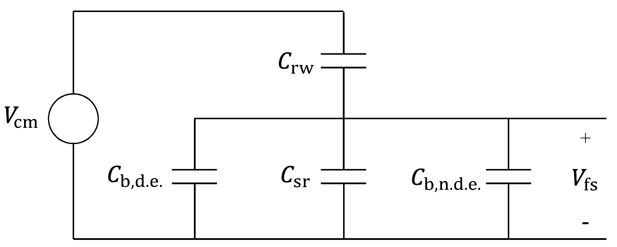
Various factors can contribute to the shaft-to-frame voltage, but a number of studies present that the voltage can be expressed as a function of winding-to-rotor capacitance , rotor-to-stator capacitance , and bearing capacitance . Figure 1 shows an equivalent circuit that expresses relations between the voltages and the capacitances [8]. In the figure, is common-mode voltage, and and are capacitances of bearings attached to drive-end (D.E.) and non-drive-end (N.D.E.) shaft-ends, respectively. The circuit can be interpreted as a voltage divider composed of capacitors, so the shaft-to-frame voltage can be calculated as follows:
where
It is reported that shaft-to-frame voltages tend to follow the shape of common-mode voltage but scaled by bearing voltage ratio (BVR) [9,10]. By inspecting Equations (1) and (2), to reduce , we should decrease or adjust the capacitance values so that is reduced.
To reduce BVR, we need to change the values of capacitances in Equations (1) and (2), but the modifications are not available due to various design and manufacturing constraints. For example, rotor-to-stator capacitance is a function of airgap length, rotor diameter, and core stack length, all of which are closely related to performances of machines. Common-mode voltage is determined by inverter and it directly determines performance. and are determined by bearing structure and cannot have meaningful effects on the value of BVR, because they are much smaller than [11]. Considering these limitations, we can only modify the value of the winding-to-rotor capacitance .
3. Slot Opening Shape Modification
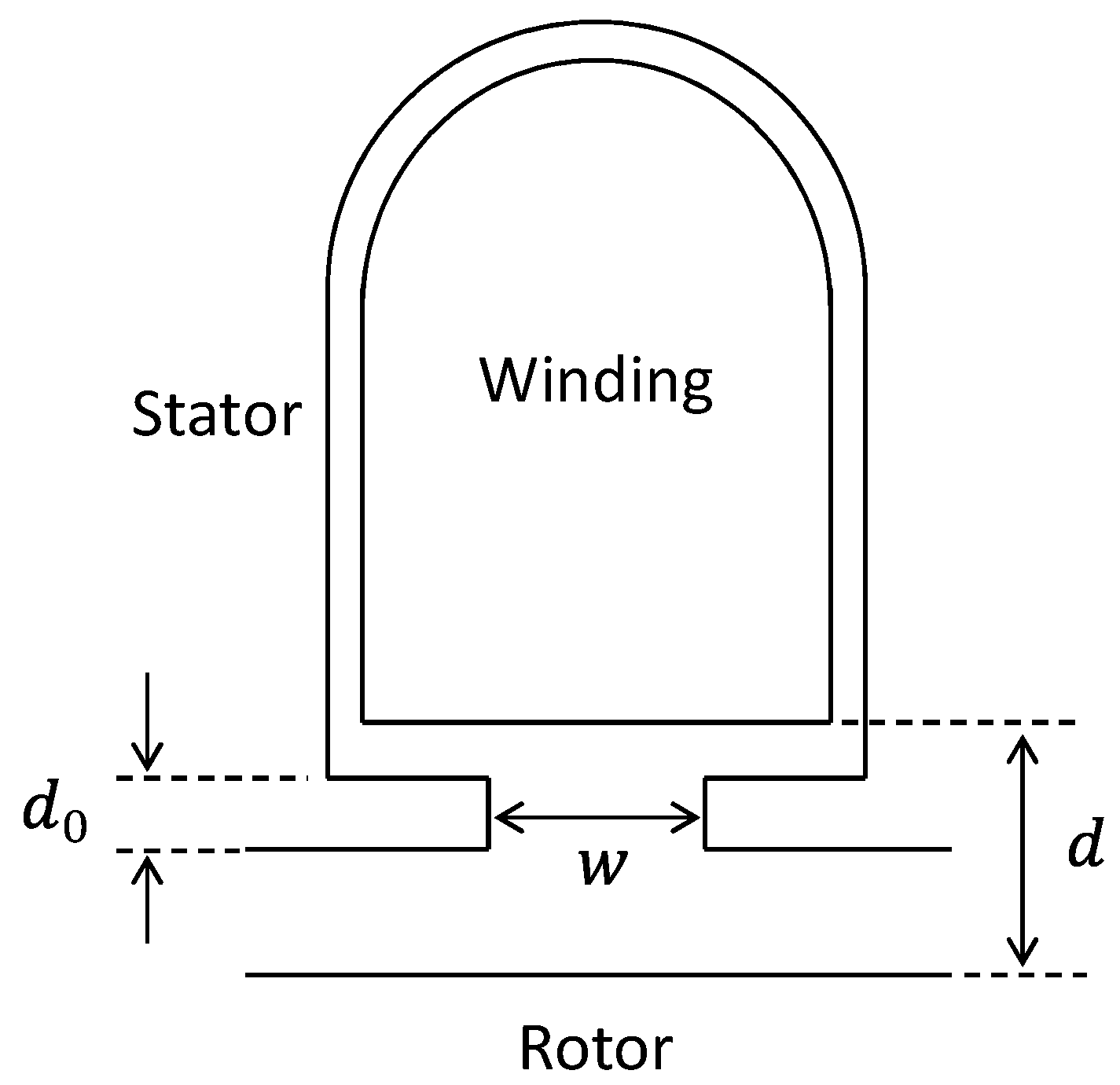
A simplified cross-section of a stator slot is described in Figure 2. A study shows that the winding-to-rotor capacitance is a function of distance from winding to rotor, core stack lamination length, and slot shape [8]. The capacitance can be estimated by using parallel-plate capacitor approximation between the windings and rotor, the which leads to
where Q is the number of stator slots, and L is the core stack lamination length. The approximation is slightly inaccurate because it assumes all electric fields between the windings to the rotor surface are vertical and orthogonal to the rotor surface, ignoring the effect of slot teeth attracting the fields. Although more accurate capacitance calculation can be found [11,12], at least we can use Equation (3) to predict the overall tendency of the winding-to-rotor capacitance with changed slot dimensions.
To reduce the winding-to-rotor capacitance , we can change the values of Q, L, and/or d in Equation (3), but their changes can also reduce the air-gap flux density and torque. Hence, in order not to affect the machine performances, we should reduce the slot opening width w, as supported by previous studies showing that the effect of modified slot openings on the machine performances is slight or ignorable [13,14].
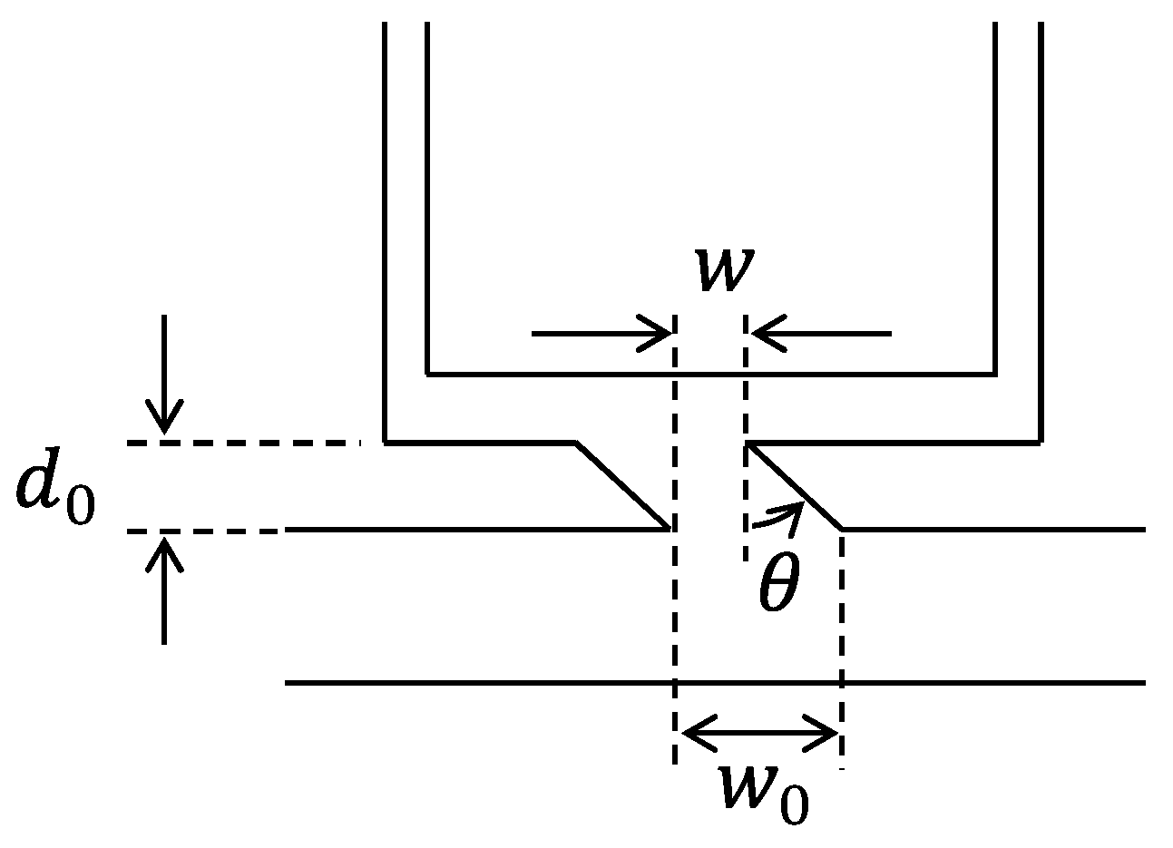
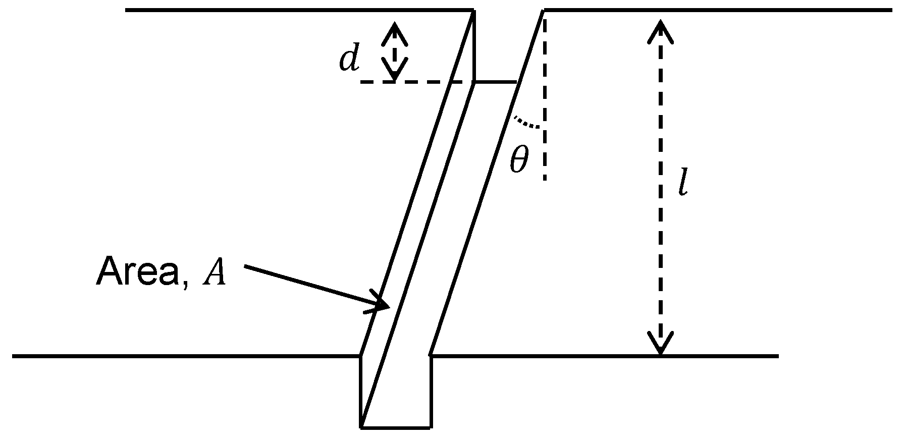
However, we need to consider other limitations on decreasing the slot opening width. The reduced slot opening will increase the leakage magnetic flux between adjacent slot teeth. In addition, a minimum slot width should be provided for proper winding process during the manufacturing of motors. To address these limits and further reduce the winding-to-stator capacitance, oblique slot opening shape can be applied as described in Figure 3. This suggested shape can block more electric flux lines with additionally decreased slot opening width by and . The decreased slot opening width can be calculated as follows:
Provided with the fixed values of and , we can adjust to change effective slot opening width, reducing the winding-to-rotor capacitance.
Currently, most induction machines are automatically wound up. This makes it difficult to implement the suggested method. Therefore, for motors that are made with certain methods, such as using hairpin winding or segmented stator-core, are more suitable with the suggested method. In addition, the suggested method can be applied not only to induction machines but also different types of electrical machines that have slot openings.
4. Verification by Finite Element Analysis
To verify that the oblique slot opening shape can further reduce the winding-to-rotor capacitance, we analyzed and compared six different slot opening shapes, parameters of which are shown in Table 1. The analyses were done with a finite element analysis (FEA) software (Ansys Maxwell). The parameter values of the reference design (Ref. in Table 1) are of a commercial 3.7-kW three-phase, four-pole, squirrel-cage induction machine. The machine has a core-stack length of 150 mm, a air-gap length of 0.35 mm, 36 stator slots, and a radial distance of 2 mm between the winding and the rotor, including the air-gap. The other five cases in Table 1 have the same design parameters with Ref., except for those shown in the table. By comparing the analysis results, we can confirm the effectiveness of the reduction of slot opening width and the introduction of obliquity in slot opening shape.
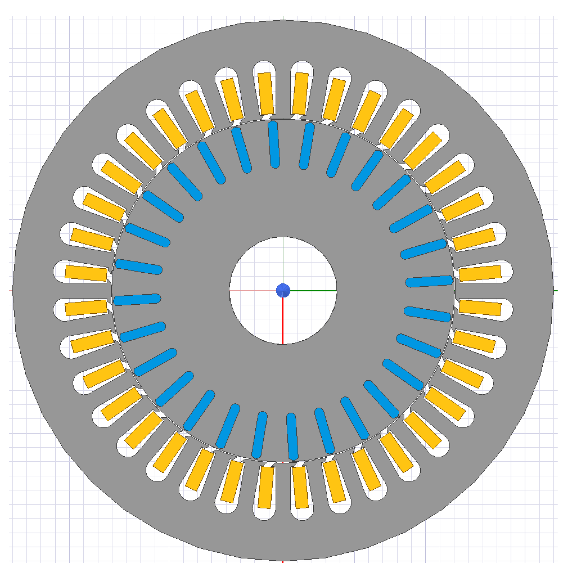
The analyses were done with a finite element analysis (FEA) software (Ansys Maxwell) with electro-static solver. Boundary condition is defined so that stator- and rotor-cores have zero potential and winding has 380 V potential. The reason we determined rotor-core’s potential as zero, although it can be floating, is that it can help us to more clearly see the coupling relation between winding and rotor surface. Figure 4 depicts a cross-section model of Case 2 in Table 1 for simulation.
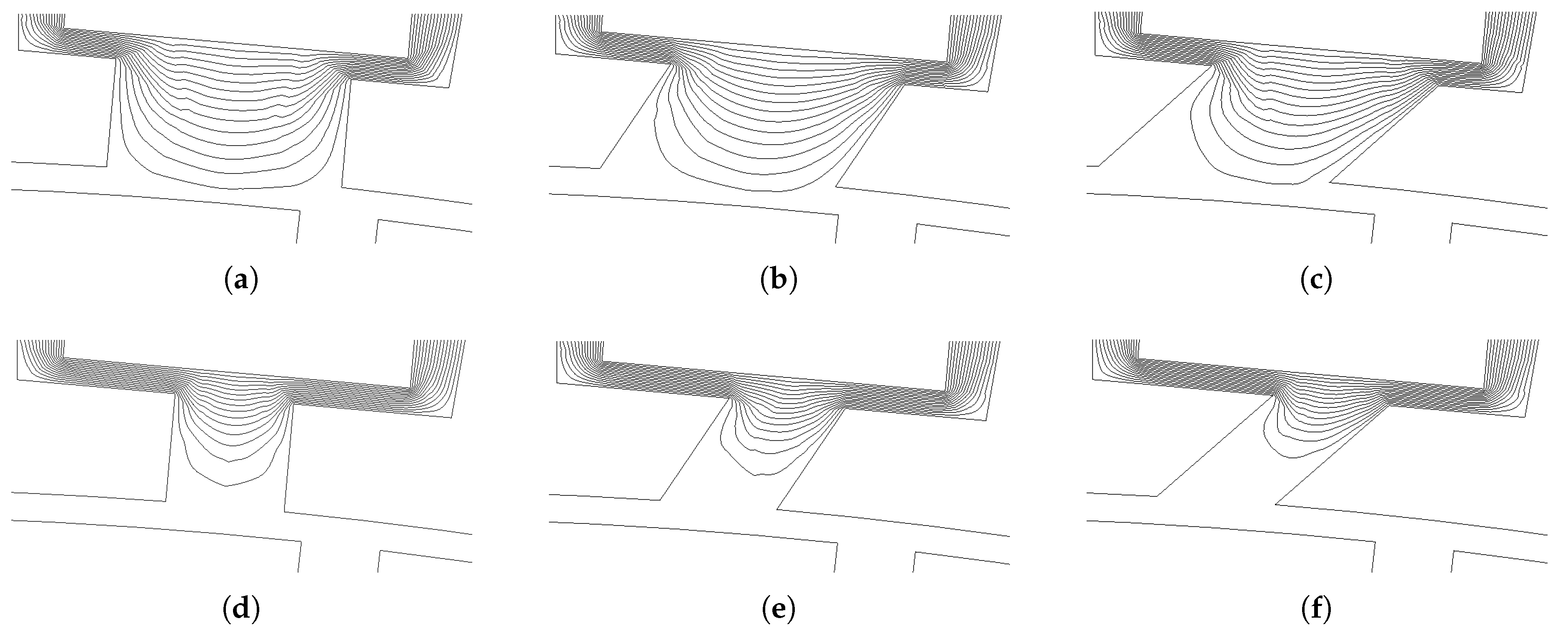
Figure 5 shows the calculated two-dimensional equipotential lines for each case. Each plot in the figure qualitatively shows that, in the order from (a) to (e), electric fields are more blocked by slot teeth, leading to the reduction of the winding-to-rotor capacitance.
The calculated values of the capacitances and the performance parameters are listed in Table 2, where the performance parameters are calculated when slip is . As we used Ansys Maxwell transient solver for simulations, torque calculation is done by using Maxwell stress tensor method [15]. Efficiency calculation is done using the equation below,
where avg is time-average at steady-state, , and . is mechanical angular velocity, and is mechanical torque. Losses due to finite conductance and core eddy current are calculated internally in the FEM solver. Winding-to-rotor capacitances of the table are in accordance with Figure 5. With the decreased slot opening width, the rotor-to-stator capacitances are slightly increased. This is because the air-gap length is fixed and the total area of the stator surface facing the rotor is just a little increased. By observing the results in the table, we can conclude that, although reduction of slot opening width decreases BVR, slot opening obliquity can also reduce BVR. Torques and efficiencies in the table guarantee that the slot opening shape modifications do not affect the machine performances.
As shown in Table 2, we also calculated winding-to-stator capacitance values for each case. The calculated values mean that decreased slot opening width and slot opening obliquity both increase the capacitance. It is important in the sense that, generally, increased winding-to-stator capacitance value leads to decreased common-mode impedance of electrical machines and increased risk of partial discharges and damages of insulation between coils at sudden surges or voltage spikes. Therefore, when applying this method, it will be better to check insulation strength is enough to prevent partial discharges using methods, such as shown in Reference [16].
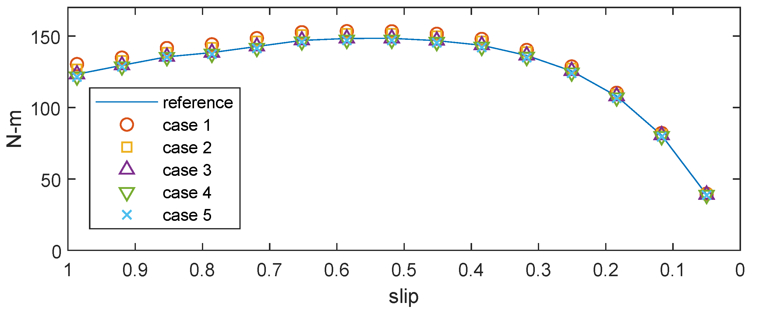
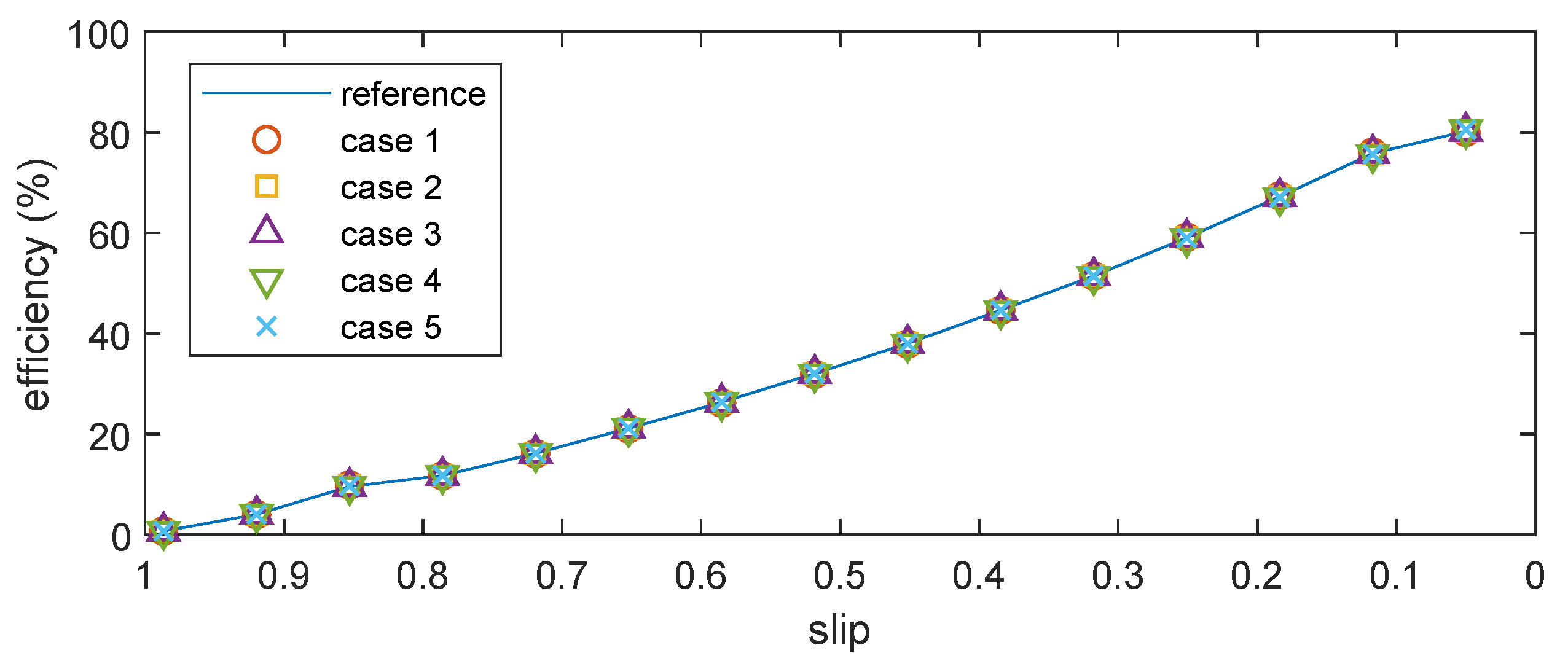
To further investigate the effects of the oblique slot opening on the performances, we calculated torques and efficiencies at different slips.The calculated results are summarized in Figure 6 and Figure 7. As shown in the figures, differences in the torque and the efficiency characteristics are insignificant among the tested cases. From the observations, we can guarantee that reduction of slot opening width and the introduction of obliquity do not affect the machine performances.
4.1. Effect of Skewed Rotor
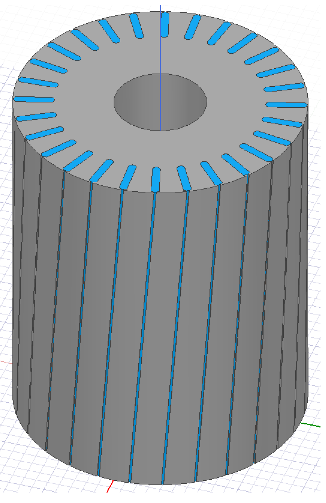
Medium power motors as used in our example cases are usually made with skewed rotor slots. Therefore, it is worth to investigate the effect of skewed rotors on the capacitance values in relation with the suggested method. We applied 5 and 10 skewnesses on rotors of Ref. and Case 2 in Table 1 and computed the related capacitance values of them. An example of rotor with 10 of skewness is presented in Figure 8. Simulation results are shown in Table 3.
It is shown in the table that the skewness of rotor slightly increased both rotor-to-stator and winding-to-rotor capacitances. This is due to the fact that rotor slot opening teeth side area is increased due to the skewness as shown in Figure 9. The area can be expressed as below.
where is total number of rotor slots. However, increased value of rotor-to-stator capacitance value is much bigger than that of winding-to-rotor capacitance value. This is because winding-to-rotor capacitance is also strongly affected by stator slot structure.
The resultant BVR values due to the skewnesses are decreased, because, in Equation (2), rotor-to-stator capacitance is placed only in the denominator. However, it also can be seen that the change of values of BVR due to the skewness has negligible impact than obliquity of slot opening.
4.2. Slotting Effect
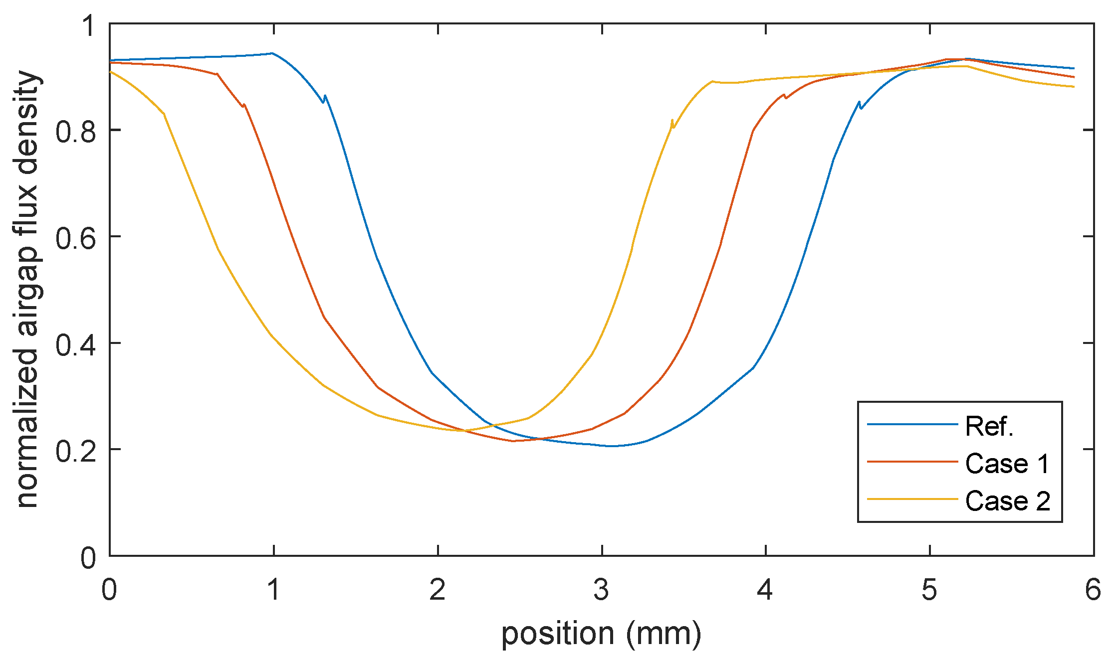
Stator slotting effect on the magnetic-field distribution is important that it induces motor’s eddy current core loss [17,18]. To investigate effect of the suggested slot opening shape on the slotting effect, we calculated airgap magnetic flux density around a single slot of Ref., Case 1, and Case 2 of Table 1. The simulation results are shown in Figure 10 and Figure 11.
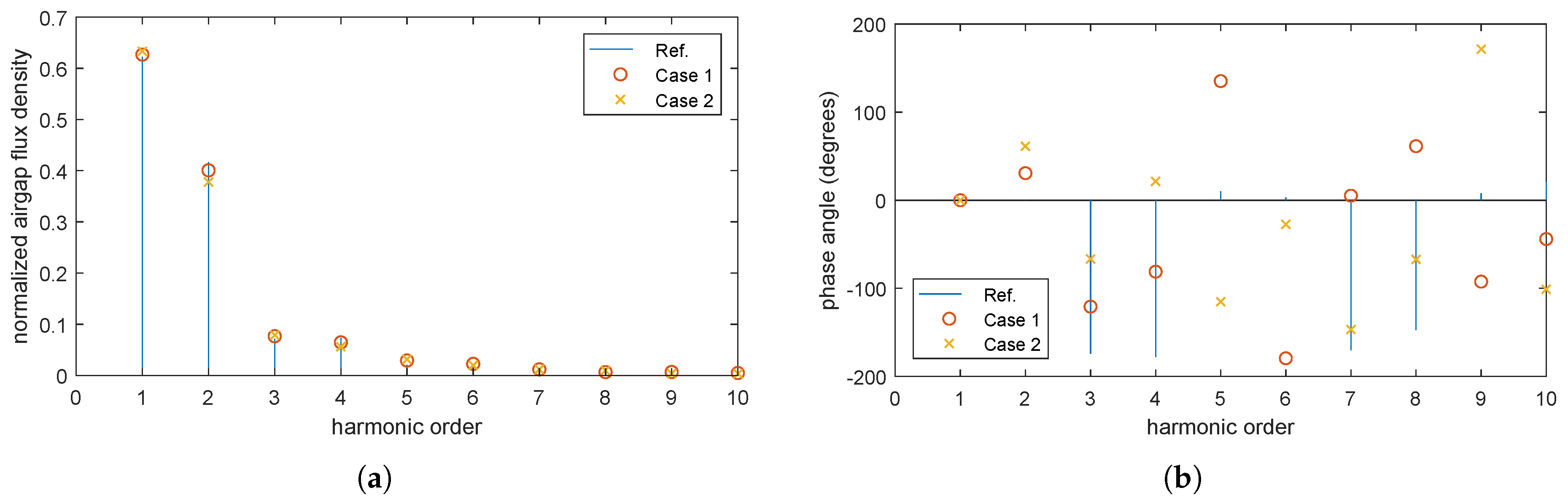
As shown in the figures, the three cases do not differ except for phase difference. Because losses due to slotting effect are caused by rotating motion of rotor relative to space harmonic airgap flux density, the suggested slot opening shape does not change the loss characteristics of motors.
5. Discussion
For the reduction of the winding-to-rotor capacitance, oblique slot opening shape is proposed in this paper. The proposed slot opening shape is verified by analyzing six different slot opening designs with FEA. The analysis results show that the suggested shape reduces the winding-to-rotor capacitance by about 98% compared to a reference design, while not affecting the machine performances.
Author Contributions
M.Y. initially developed and analyzed the design as the first author. K.J.H. led and supervised this work to provide more solid analysis results with different design cases as the corresponding author. All authors have read and agreed to the published version of the manuscript.
Funding
This research was supported by Korea Electric Power Corporation. [Grant number: R17XA06-74].
Conflicts of Interest
The authors declare no conflict of interest.
References
- Asefi, M.; Nazarzadeh, J. Survey on High-Frequency Models of PWM Electric Drives for Shaft Voltage and Bearing Current Analysis. IET Electr. Syst. Transp. 2017, 7, 179–189. [Google Scholar] [CrossRef]
- Shami, U.T.; Akagi, H. Identification and Discussion of the Origin of a Shaft End-to-End Voltage in an Inverter-Driven Motor. IEEE Trans. Power Electron. 2010, 25, 1615–1625. [Google Scholar] [CrossRef]
- Hadden, T.; Jiang, J.W.; Bilgin, B.; Yang, Y.; Sathyan, A.; Dadkhah, H.; Emadi, A. A Review of Shaft Voltages and Bearing Currents in EV and HEV Motors. In Proceedings of the IECON 2016—42nd Annual Conference of the IEEE Industrial Electronics Society, Florence, Italy, 23–26 October 2016. [Google Scholar]
- Ren, X.; Liu, R.; Yang, E. Modelling of the Bearing Breakdown Resistance in Bearing Currents Problem of AC Motors. Energies 2019, 12, 1121. [Google Scholar] [CrossRef] [Green Version]
- Kalaiselvi, J.; Srinivas, S. Bearing Currents and Shaft Voltage Reduction in Dual-Inverter-Fed Open-End Winding Induction Motor with Reduced CMV PWM Methods. IEEE Trans. Ind. Electron. 2015, 62, 144–152. [Google Scholar] [CrossRef]
- Luu, T.; Shudarek, T. An integrated inverter output passive sinewave filter for eliminating both common and differential mode PWM motor drive problems. In Proceedings of the IEEE Applied Power Electronics Conference and Exposition (APEC), Tampa, FL, USA, 26–30 March 2017. [Google Scholar]
- Lee, S.T.; Park, J.K.; Jeong, C.L.; Rhyu, S.H.; Hur, J. Shaft-to-Frame Voltage Mitigation Method by Changing Winding-to-Rotor Parasitic Capacitance of IPMSM. IEEE Trans. Ind. Appl. 2018, 55, 1430–1436. [Google Scholar] [CrossRef]
- Muetze, A.; Binder, A. Calculation of Motor Capacitance for Prediction of Voltage across Bearings. IEEE Trans. Ind. Appl. 2007, 43, 665–672. [Google Scholar] [CrossRef]
- Bai, B.; Wang, Y.; Wang, X. Suppression for Discharging Bearing Current in Variable-Frequency Motors Based on Electromagnetic Shielding Slot Wedge. IEEE Trans. Magn. 2015, 51, 8109404. [Google Scholar] [CrossRef]
- Liu, R.; Ma, X.; Ren, X.; Cao, J.; Niu, S. Comparative analysis of bearing current in wind turbine generators. Energies 2018, 11, 1305. [Google Scholar] [CrossRef] [Green Version]
- Adabi, J.; Zare, F.; Ghosh, A.; Lorenz, R.D. Calculations of capacitive couplings in induction generators to analyse shaft voltage. IET Power Electron. 2010, 3, 379–390. [Google Scholar] [CrossRef] [Green Version]
- Ahola, J.; Muetze, A.; Niemela, M.; Romanenko, A. Normalization-Based Approach to Electric Motor BVR Related Capacitances Computation. In Proceedings of the IEEE Applied Power Electronics Conference and Exposition (APEC), San Antonio, TX, USA, 4–8 March 2018. [Google Scholar]
- Liu, T.; Huang, S.; Gao, J.; Lu, K. Cogging Torque Reduction by Slot-Opening Shift for PM Machines. IEEE Trans. Magn. 2013, 49, 4028–4031. [Google Scholar] [CrossRef]
- Abbaszadeh, K.; Jafari, M. Optimizing Cogging Torque Reduction in Slot Opening Shift Method for BLDC Motor by RSM. In Proceedings of the 2011 2nd Power Electronics, Drive Systems and Technologies Conference, Tehran, Iran, 16–17 February 2011. [Google Scholar]
- Meessen, K.J.; Paulides, J.J.H.; Lomonova, E.A. Force calculations in 3-D cylindrical structures using Fourier analysis and the Maxwell stress tensor. IEEE Trans. Magn. 2012, 1, 536–545. [Google Scholar]
- Yea, M.; Han, K.J.; Park, J.; Lee, S.; Choi, J. Design optimization for the insulation of HVDC converter transformers under composite electric stresses. IEEE Trans. Dielectr. Electr. Insul. 2018, 25, 253–262. [Google Scholar] [CrossRef]
- Tong, C.; Song, Z.; Bai, J.; Liu, J.; Zheng, P. Analytical investigation of the magnetic-field distribution in an axial magnetic-field-modulated brushless double-rotor machine. Energies 2016, 9, 589. [Google Scholar] [CrossRef] [Green Version]
- Wills, D.A.; Kamper, M.J. Analytical prediction of rotor eddy current loss due to stator slotting in PM machines. In Proceedings of the IEEE Energy Conversion Congress and Exposition, Atlanta, GA, USA, 12–16 September 2010. [Google Scholar]
Figure 1.
Circuit diagram describing shaft-to-frame voltage.

Figure 2.
Cross-sectional diagram of a slot.

Figure 3.
A slot with oblique slot opening shape.

Figure 4.
A cross-section model of Case 2 in Table 1 for simulation.
Figure 4.
A cross-section model of Case 2 in Table 1 for simulation.

Figure 5.
Calculated equipotential lines of (a) Ref., (b) Case 1, (c) Case 2, (d) Case 3, (e) Case 4, and (f) Case 5.
Figure 5.
Calculated equipotential lines of (a) Ref., (b) Case 1, (c) Case 2, (d) Case 3, (e) Case 4, and (f) Case 5.

Figure 6.
Calculated torques at different slips.

Figure 7.
Calculated efficiencies at different slips.

Figure 8.
An example 3D model of skewed rotor for simulation with 10 of skewness.

Figure 9.
Rotor surface area change due to skewness.

Figure 10.
Normalized airgap densities of Ref., Case 1, and Case 2 of Table 1 around a single slot.
Figure 10.
Normalized airgap densities of Ref., Case 1, and Case 2 of Table 1 around a single slot.

Figure 11.
(a) Magnitude and (b) phase angle plots of the normalized airgap flux densities in Figure 10 in spatial frequency domain.
Figure 11.
(a) Magnitude and (b) phase angle plots of the normalized airgap flux densities in Figure 10 in spatial frequency domain.


Table 1.
Slot opening dimension parameters.
| Ref. | Case 1 | Case 2 | Case 3 | Case 4 | Case 5 | |
|---|---|---|---|---|---|---|
| (mm) | 3 | 3 | 3 | 1.5 | 1.5 | 1.5 |
| (mm) | 1.38 mm | 1.38 | 1.38 | 1.38 | 1.38 | 1.38 |
Table 2.
Calculated capacitances and performance parameters at . BVR = bearing voltage ratio.
| Ref. | Case 1 | Case 2 | Case 3 | Case 4 | Case 5 | |
|---|---|---|---|---|---|---|
| (pF) | 30.15 | 24.57 | 16.59 | 3.93 | 2.05 | 0.46 |
| (pF) | 1145.90 | 1159 | 1179.4 | 1339.30 | 1342.21 | 1354.30 |
| BVR (%) | 2.56 | 2.08 | 1.39 | 0.29 | 0.15 | 0.03 |
| Torque (N-m) | 39.03 | 39.64 | 39.47 | 39.03 | 38.85 | 38.64 |
| Efficiency (%) | 80.22 | 80.02 | 80.27 | 80.22 | 80.48 | 80.54 |
Table 3.
Calculated capacitance values with skewed rotors.
| Ref. | Case 2 | |||||
|---|---|---|---|---|---|---|
| skew 0 | skew 5 | skew 10 | skew 0 | skew 5 | skew 10 | |
| (pF) | 30.15 | 30.22 | 30.27 | 16.59 | 16.74 | 16.91 |
| (pF) | 1145.90 | 1171.6 | 1233 | 1179.4 | 1212.6 | 1277.5 |
| BVR (%) | 2.56 | 2.51 | 2.40 | 1.39 | 1.36 | 1.31 |
© 2020 by the authors. Licensee MDPI, Basel, Switzerland. This article is an open access article distributed under the terms and conditions of the Creative Commons Attribution (CC BY) license (http://creativecommons.org/licenses/by/4.0/).
Share and Cite
MDPI and ACS Style
Yea, M.; Han, K.J. Modified Slot Opening for Reducing Shaft-to-Frame Voltage of AC Motors. Energies 2020, 13, 760. https://0-doi-org.brum.beds.ac.uk/10.3390/en13030760
AMA Style
Yea M, Han KJ. Modified Slot Opening for Reducing Shaft-to-Frame Voltage of AC Motors. Energies. 2020; 13(3):760. https://0-doi-org.brum.beds.ac.uk/10.3390/en13030760
Chicago/Turabian StyleYea, Manje, and Ki Jin Han. 2020. "Modified Slot Opening for Reducing Shaft-to-Frame Voltage of AC Motors" Energies 13, no. 3: 760. https://0-doi-org.brum.beds.ac.uk/10.3390/en13030760
Note that from the first issue of 2016, this journal uses article numbers instead of page numbers. See further details here.