Article

CFD Simulations for Performance Enhancement of a Solar Chimney Power Plant (SCPP) and Techno-Economic Feasibility for a 5 MW SCPP in an Indian Context

by
Arijit A. Ganguli
1,2,*,
Sagar S. Deshpande
2 and
Aniruddha B. Pandit
2
1
School of Engineering and Applied Sciences, Ahmedabad University, Ahmedabad 380009, India
2
Institute of Chemical Technology, Mumbai 400019, India
*
Author to whom correspondence should be addressed.
Submission received: 6 April 2021 / Revised: 29 May 2021 / Accepted: 31 May 2021 / Published: 7 June 2021
(This article belongs to the Special Issue Recent Advances in Solar Power Plants)

Abstract

:
The use of solar energy for power generation using the innovative solar chimney concept has been explored by many researchers mostly with the help of analytical models as well as CFD simulations while experimental studies for a pilot and bench scale facilities have been carried out. The efficiencies of these chimneys, however, are less than 1% (~0.07% for 50 kW pilot plant similar to Manzanares plant in Spain). In the present study, an effort has been made to make modifications in the chimney design to improve the efficiency of the chimney in terms of power generation. CFD simulations have been carried out for this modified design and the efficiency is seen to improve to 0.12% for a 50 kW chimney. Furthermore, a techno-economic feasibility analysis has been carried out for a conventional 5 MW solar power plant which can be installed on the western part of India, which receives good solar irradiation throughout the year. Two cases with and without government subsidies have been considered. It is observed that a high rate of return (~20.4%) is obtained for a selling price of electricity of Rs 5 per kWh with government subsidy, while a rate of return of ~19% is obtained for Rs 10 per kWh without government subsidy.

1. Introduction

Solar energy as a form of renewable energy has become more widespread in the last few years in countries such as India due to the huge lands being used for making solar parks in places where there is sunlight throughout the year. The photovoltaic cells, concentrated troughs etc. are used to generate electricity across the globe. The land being used is particularly barren land. A viable option is energy being produced along with cultivation occurring on the land. This can be achieved using the concept of a solar chimney. The solar chimney has been an area of research for a few decades, since Schlaich [1] and co-workers designed, constructed and operated the first Solar Chimney Power Plant (SCPP) in Manzanares, Spain. Though many projects for the implementation of SCPPs have been proposed in various countries after this, real construction and operation of such power plants have not taken place [2]. The typical design and workings of a solar chimney are as follows: a solar chimney consists of a base (ground) and a solar collector at a certain height from the ground covering the entire ground. A cylindrical chimney is constructed at the center of the collector. A typical schematic of the solar chimney is shown in Figure 1.
A Conventional Solar Chimney Power Plant (CSCPP) consists of a collector (1) which may be straight or inclined, covering the ground (2). The space between the collector and the ground (3) is heated due to solar energy. A vertical cylindrical chimney (4) of height H and diameter D1 is situated at the center of the collector. As the air temperature in (3) increases, hot air starts to move towards the collector center and then into the chimney, while cold air from the atmosphere enters to occupy the volume vacated by the hot air. A turbine (6) is placed at the center between the collector (2) and chimney (4). The turbine moves and generates electricity, giving the necessary power output.
In Section 2.1, a literature review is done of the recent works involving experimental, analytical, CFD simulations and technoeconomic feasibility, with an aim to understand recent trends of research and the gap between the current trend and practical implementation. Furthermore, to study the economic feasibility of solar power plants into an Indian context, the technoeconomic feasibility studies that have been carried out in the last few years need to be understood. The normal cost of electricity (from thermal sources) in India is currently Rs 10 per kWhr (which includes tariff), though it might vary in different parts of the country depending on rural and urban areas and different Indian states [3]. Furthermore, the cost and time required to build a 500 MW solar power plant is 2–3 times more than similar capacity thermal and hydro power projects. The cost of labor in India is five times lower than in the Middle East. The climatic conditions in India are 240–300 sunny days in a year and land acquisition has become easier since 2016 due to the government’s solar park policies [4]. Furthermore, solar power is expected to become the second largest source of power in India. In such scenarios, a solar chimney with modifications can become a game changer. In Section 2.2, we carry out an extensive literature review of the technoeconomic feasibility.

2. Literature Review

2.1. Present Status of Solar Chimneys Involving Experimental, Analytical Work and CFD Simulations

Reviews on solar chimneys have been carried out by few researchers [2,5]. With an increasing need for solar power, SCPP technology would depend on improving the overall efficiency of solar energy into electrical power. This would need not only improvements of the basic design of the chimney or geometrical changes using experimental, numerical or analytical techniques [6,7,8,9], but also of the materials of the collector, such as the photovoltaic cells, phase change materials etc. [9,10]. The advent of hybrid systems has also gained importance, examples being the integration of waste to energy plants with solar chimney [11] and the concept of solar chimney with wind super charging. Furthermore, economic feasibility needs to be checked for the successful implementation of the project. Some researchers [12,13] have suggested agricultural land to be used for greenhouses. Details of prominent experimental, analytical and numerical works has been provided by Ganguli and Deshpande [14]. Experimental works for geometric modifications of chimneys have been carried out by various researchers [15,16,17,18]. Important works have been carried out in the area of thermodynamic [19,20] and exergy analysis [21,22]. In the sub-sections, recent experimental works focusing on bench scale SCPP systems (Chimney Height and Collector diameter less than 10 m) have been illustrated. Furthermore, the works include innovations on collector materials, slope of the collector from outlet to inlet or vice versa, variation in the chimney area from bottom to top, parameters such as the chimney diameter, chimney height and use of electrical power output from smaller SCPPs for running household devices. Numerical works include the effect of obstructions on the flow patterns in the space between ground and collector, change in the geometry of the collector or chimney by changing the area of inlet and outlet of the chimney or collector, changing the collector materials by using photovoltaic cells instead of glass or plastic and having hybrid systems (SCPP combined with hot gases) to generate more power.

2.1.1. Experimental Works

The prominent experimental works of smaller sized solar chimneys carried out by various researchers in recent years have been provided in Table 1. This includes the chimney size details, the power generated by the set-ups and the parameters studied in these setups. The research works of the researchers are explained below.
Fadaei et al. [10] have used phase change material (PCM) as collector material for absorbing the solar energy in a conventional SCPP design. The authors claimed a minor increase in the air velocity and absorber surface temperature, suggesting that a limited increase in power output is possible. The authors emphasized that the use of PCM may be very useful for the plant to run during the night, since energy is stored in the PCM.
Ghalamchi et al. [15] carried out experimental investigations on a small-scale solar chimney setup in Zhanzhan, Iran. The authors constructed an experimental setup with 3 m height and 3 m diameter with the objective to procure new experimental data and find a correlation between geometric parameters. Two materials (aluminum and iron) for the absorber were tested, and it was found that aluminum was better than iron as a material. A sensitivity analysis was carried out by changing two geometric parameters, namely the height of the chimney above the ground and the chimney height and diameter. The authors observed 55.3% higher power output for a chimney with a height of 3 m as compared to a 2 m and lower height of the chimney from the ground. The authors also concluded that the chimney diameter was most influential for power generation, while an optimum height needs to be chosen to avoid a decreasing power output. Though these findings have been found by researchers in the past for Manzanares SCPP, Ghalamchi et al. confirmed it for a small-scale chimney.
Mekhail et al. [16] performed experimental and theoretical investigations on a bench scale SCPP (collector diameter of 6 m, chimney height of 6 m and collector diameter of 0.15 m). The authors investigated diurnal variations of temperature on the overall power being produced during the day. The authors developed a mathematical model by perfrming energy balance across the system and validated their model with experimental data.
Balijepalli et al. [17] carried out experimental investigations on an SCPP with a power output of 0.82 kW (with a diameter of 0.6 m and height above ground of 0.1 mm and a collector with a diameter of 3.5 m and a chimney height of 6 m). The SCPP has a diverging collector. The authors used a single theoretical model to calculate the overall efficiency of the plant and the power produced. The authors found the pressure drop across the turbine to be very low, i.e., around 4 N/m2. The authors concluded that such SCPPs can be used to run household devices such as LED TVs, fans, refrigerators, laptop etc. for a specific time duration with a total investment of around 0.5 million Indian Rupees, which would be an important step towards power self-sufficiency in rural households.
Khidir and Atrooshi [18] carried out experimental investigations for an innovative type of collector design. The authors paid special attention for tracking the sun path both diurnally and yearly. The authors have also built a mathematical model and validated the data with experiments. Their work is of significance especially to areas where natural land inclination is unavailable.
Mehdipour et al. [23] attributed the low efficiencies of SCPPs to the existence of secondary flows that cause high thermal and frictional losses. The authors claimed that only 9% of the input energy is responsible for generating power, and the rest is lost due to secondary flows. The authors have suggested that increasing the collector area may not be a good option, since it improves the chimney performance marginally while increasing the capital investment.
Table 1. Literature on prominent and recent research experimental works.
AuthorSCPP DetailsGeometric ModificationDeliverablesPower
Generation Data (kW)
ReferenceChimney Height (m)Chimney Diameter (m)Collector Diameter (m)Elevation from GroundTypeCollector Angle
Ghalamchi et al. [15]30.02530.04–0.14Conventional SCPP0NASpatial Temperature and velocity variation, power output1–1.6
Mekhail et al. [16]60.156 Diverging collector conventional SCPPNANATemperature variation across the day, power output2–3
Khidir and Atrooshi, [18]7.350.390.3 m at entry and 1.3 m at collector outDiverging collector conventional SCPPNANAVelocity, temperature variation and solar irradiation over the entire day period0.8–1
Balijepalli et al. [17]60.63.50.1Diverging collector conventional SCPPNANAPower output, techno-economic analysis0.82
Mehdipour et al. [23]0.194–0.250.011.130.015–0.03Converging collector conventional SCPP0–20NACollector angle, height of collector above groundNA
Table 2. Literature on prominent numerical research works.
AuthorSCPP DetailsDeliverablesCFD Details
ReferenceChimney Height (m)Chimney Diameter (m)Collector Diameter (m)Elevation from GroundType DimensionGrid DetailsTurbulence ModelBoundary ConditionsCFD Software
Guo et al. [19]194.624410.161.85Conventional ChimneyTurbine Output, Turbine pressure drop, System efficiency, Turbine efficiency3DGrid number of solar chimney = 1,200,000
Grid number of turbine = 700,000
k–ε turbulence modelT_enironment = 302 K P_inlet = 0 Pa
P_outlet = 0 Pa
Ansys Fluent Fan model
Nia et al. [24]12100.250.15–1Diverging collector chimneyStream lines of velocity, Turbulent kinetic energy along the collector, Nusselt number3DGrid is composed of 219,417 quadratic elements k–ε turbulence modelT_enironment = 320 K P_inlet = P_atm P_outlet = P_atm2D axisymmetric incompressible steady CFD solver
Liu et al. [25]5502512503Conventional Chimneysolar radiation, power capacity, temperature increase, SCPP power productivity3DCombination of coarse and fine meshRNG k–ε
turbulence model
Tinlet = 300 k,
Toutlet = 300 k; h = 9.5 W/m2 K
Inhouse code
Gholamalizadeh and Kim [26]200102402Conventional ChimneyVelocity and temperature distribution3DCombination of coarse and fine mesh RNG k–ε turbulence model Adiabatic wall for bottom and sides of heat storage; h = 9.5 W/m2 K; Pinlet = 0 Pa; Poutlet = 0 Pa Ansys Fluent
Singh et al. [9]3bottom: 0.1; inlet: outlet = 1–53Inlet: 6–18 cm; Outlet: 6 cm Diverging collector, Diverging ChimneyTemperature and velocity contours; pressure contours 2D axisymmetricGrid number of solar chimney = 114,600k–ε turbulence modelAdiabatic for chimney wall; h = 9.5 W/m2 K; Pinlet = 0 Pa; Poutlet = 0 Pa
Hu et al. [8]Hu et al. 2017195244101.8DSC, DISC, DOSCPower output; pressure pressure profiles2D axisymmetricCombination of coarse and fine meshRealizable k–ε turbulence model

2.1.2. Numerical Works

In Table 2, some of the important numerical works, with details such as size, type of chimneys selected for simulation and parameters studied and CFD details such as grid sizes, turbulence model selected and boundary conditions, have been presented. The prominent numerical studies of the researchers have been described below.
Guo et al. [19] have performed 3D CFD simulations of an SCPP, including a real turbine. The effect of the angle of sunlight on SCPP performance was investigated. The authors found that the variation of this angle played an important role in the SCPP performance.
Nia and Ghazikhani [24] carried out 2D axisymmetric simulations to passively control the air flow in the region between the ground and the collector. Three different flow control obstacles were chosen by the authors. The authors found that the obstacles caused improvements in the heat transfer characteristics and velocity magnitudes. The authors showed improvement in Nusselt numbers, improvement in hot and cold fluid mixing, agitation in thermal boundary layer and an overall 41.2% increase in energy output.
Hu et al. [8] carried out numerical simulations for a solar chimney with a diverging collector, which consisted of the collector diverging from the collector inlet to the chimney inlet. The authors termed this as Divergent Inlet Chimneys (DISC). Another variation would be the chimney diameter increasing from the bottom of the chimney to the top, which the authors termed as Diverging Outlet Chimneys (DOSC). The authors also called the two variations in the chimney types diffuser type chimneys (DSC), which provided better outputs (~13.5 times) than Conventional SCPPs. The authors used the areas of the chimney top to base (area ratio) as a parameter and studied the effect on the power output. Finally, the authors claimed that by having a variable diffuser outlet, stable power for 7 h of daytime, with 60% higher power output than normal chimneys, can be obtained.
Liu et al. [25] carried out numerical investigations for Solar Chimney Photovoltaic Thermal Power plants (SCPVTPP) with photovoltaic cells. The authors have suggested a mathematical model using energy balance. The authors found that a combination of photovoltaic cells (PV) and SCPP decreased the power produced by PV, which caused a decrease in the overall power output. The authors, however, also found that an increase in the collector area has an increase in the overall power output using photovoltaics.
Arzpeyma et al. [27] provided a numerical analysis of the stack configuration effect on the performance of SCPPs to provide more dependable sources. The authors have recommended a conversion of SCPPs to hybrid systems. For instance, the authors focused on having systems with more than one turbine and focused on elements such as turbine structure and operations. The authors also proposed SCPPs for air conditioner and CHP systems.

2.2. Present Status of Work on the Techno-Economic Feasibility of Solar Chimneys

The research works on techno-economic analysis regarding the feasibility of the SCPP systems using different modeling techniques are discussed in this section. The analysis by various researchers is based on the optimization of chimney dimensions followed by a techno-economic analysis [11,28,29]. Other researchers have shown the environmental impact by integrating the carbon credits and economic analysis [30,31,32] to show the positive impact on the environment, while some authors [11,33] have integrated SCPP with waste energy, after which they performed an economic analysis to show the benefits of the process. Most techno-economic analyses are based on the Levelized Cost of Electricity (LCOE).
We try to review the literature on the techno-economic analyses done for solar chimneys across the globe to understand the power output desired and to analyze the Levelized Electricity Cost (LEC) proposed by various researchers for the types and sizes of the chimneys considered. Table 3 shows the above factors considered by various authors. Each of the works are briefly presented below.
Fluri et al. [34] developed an economic analysis model based on carbon credits. The authors have compared previously developed cost models with newly developed models. The authors found that carbon credits had a major impact on the initial cost and LCOE. By inclusion of carbon credits, the initial cost is increased 2.5 to 3 times, while LCOE is increased 2.7 to 3.4 times for a large scale SCPP. They considered three different configurations [1,35,36]. A comparison showed that solar power plants may be more expensive than previously predicted. The authors suggested that the costs can be reduced by the construction of multiple plants, as also suggested by Schlaich et al. [35].
Zhou et al. [37] performed an economic analysis of a Floating Solar Chimney Power Plant (FSCPP) for a 100 MW plant. The authors found that a Rate of Return (ROR) of 8% can be obtained at 0.83 Yuan/kWh, including loans at 2% interest rate and free income tax. The authors also analyzed that FSCPP were more economical than CSCPPs of similar capacity.
Cao et al. [38] performed an economic analysis of conventional solar chimneys (on the ground) for power generation and inclined solar chimneys that can be based on mountains. The authors compared both the capital investments and operating costs for the two configurations and suggested that the inclined solar chimneys are more cost effective compared to conventional solar chimneys (CSCPP’s). Furthermore, the authors have highlighted the material of construction and carbon credits as important parameters with respect to cost-effectiveness. Solar electricity rate and inflation had an inverse effect on payback.
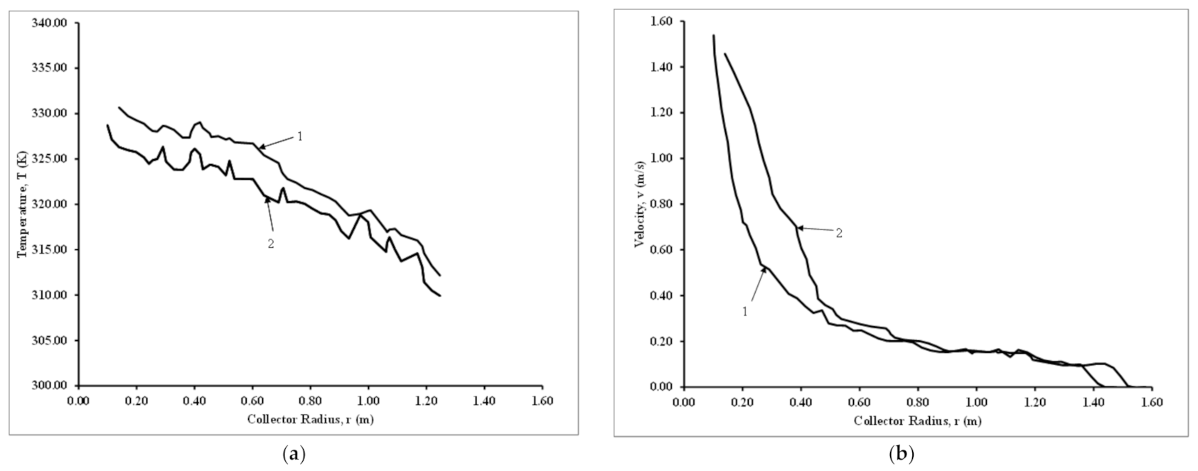
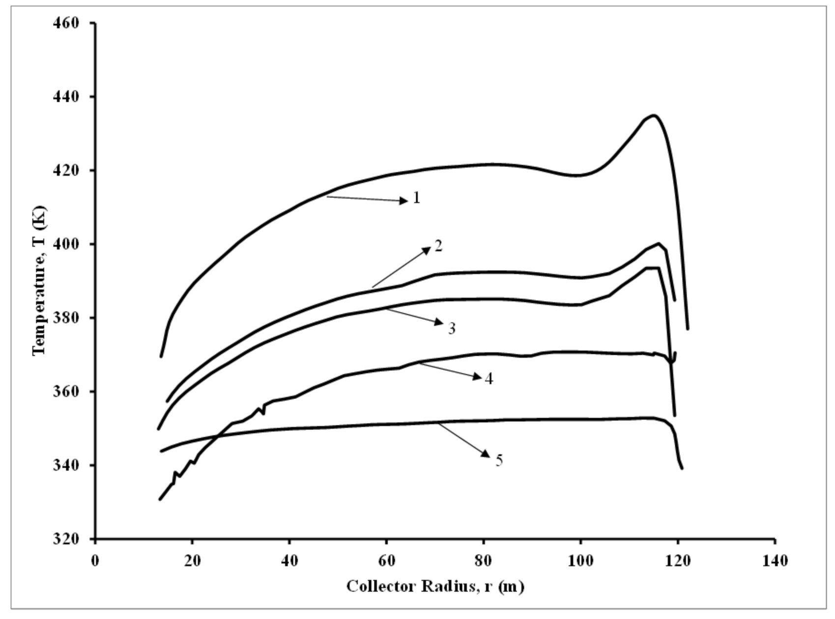
Gholamalizadeh and Mansouri [28] performed an integrated approach by first predicting SCPP performance in Kerman, Iran using analytical and numerical models and subsequently performing the cost analysis and effect of the parametric sensitivity on the cost analysis. The authors have made a comprehensive attempt to optimize the SCPP and perform a cost analysis. The authors first developed a numerical model to improve the performance of the SCPP. The velocity distribution in collector was derived analytically while the temperature distribution was obtained from numerical models. A significant contribution was defining a coefficient to show altitude effectiveness, which is informative in terms of the SCPP performance at different altitudes. A sensitivity analysis was carried out by varying collector radius for different chimney heights and chimney diameters. The authors observed expenditure minima for chimney diameters of 4 and 5 m, while the curve flattened after a certain chimney height. Due to this study, important recommendations for improvements of the SCPP performance could be provided. The power output was increased by 4 times, while the plant expenditure was reduced by 1.45 times. The authors claimed that the thermo-economically optimal power plant improved the power output by 11 times and reduced specific plant expenditure by 2.03 times compared to the existing plant.
Tawalbeh et al. [39], in a significant contribution towards the environmental impact of SCPP plants using solar photovoltaics, studied the environmental effects during the manufacturing of photovoltaic systems. The authors suggested a strategy to mitigate the negative effects on the environment and improving the sustainability of the PV manufacturing process. The authors suggested the use of novel manufacturing materials to decrease the carbon foot print by one order of magnitude. The authors stressed the need to minimize the use of hazardous materials, as well as careful site selection and recycling wherever possible in the PV manufacturing process.
Abdelslem et al. [40] studied a hybrid technique using SCPPs with cooling towers (the authors termed the technique as Hybrid Solar Chimney Power Plant (HSCPP)) for power generation and seawater desalination. The authors claimed that these integrated techniques have several advantages, including the production of 50% higher electricity generation, 40% reduced CO2 emissions and 1.4 times higher efficiency compared to a conventional SCPP.
Gholamalizadeh and Kim [26] designed a genetic algorithm to optimize the design parameters of the radius of the collector and the height and diameter of the chimney. The optimized parameters were then used to find the cost, efficiency and output power. Two case studies, the Kerman power plant, Iran and the Manzanares Power Plant, Spain, were analyzed, and optimization of each plant was done, after which the best configuration was chosen. The results showed that the increase in cost in the optimized design was lower than the increase of the power output.
Bahar et al. [30] performed a cost analysis for the Manzaranes model with cost data in a European context. The authors found that 150 MWh of electrical power can be produced yearly in Tunisia. As the size of the chimney increases, the cost of purchasing per unit decreases, and simultaneously, the use of greenhouse collectors in drying or agriculture can be helpful.
Okoye and Atikol [31] stressed the environmental impact of SCPP compared to fuel oil, and subsequently, the importance of the emission of carbon dioxide, NOx and SOx due to fuel oil and other fossil fuels, which will not occur if a SCPP system is installed. A sensitivity analysis was carried out for a 30 MW hypothetical SCPP. Parameters that were optimized include the capital expenditure, carbon credits, geometrical parameters (chimney height, chimney diameter) and SCPP plant capacity. The effect of these parameters on the economic feasibility indicators, such as Net Present Value (NPV), savings to investment ratio (SIR) and Internal Rate of Return (IRR), were calculated.
Li et al. [32] presented a model to analyze the cost and benefit of a Reinforced Concrete SCPP (RCSCPP). The authors included the benefit of carbon credits and income tax cost. Furthermore, they used the risk-adjusted discount rate method to analyze the cash flow. The authors considered that the RCSCPP can be used for 120 years and divided the service period into four phases to calculate the NPV of each phase. Hence, this kind of power plant can then be compared with a coal-fired power plant. The authors used the elasticity method for sensitivity analysis. After a detailed analysis, they found that the minimum price of electricity in phase 1 would be higher than the current market price, but will be lower than coal-fired power in the subsequent phases.
Okoye et al. [29] proposed a two-step economic feasibility based on a new non-linear programming model. The authors first performed an optimization of the geometrical parameters of the SCPP and then performed the economic feasibility analysis. The authors conceptualized an optimized the plant which has the optimal plant dimensions and an economic feasibility which considers the energy demand uncertainty in solar radiation and ambient temperature. The authors went on to carry out a detailed sensitivity analysis to understand the effects of the collector, demand per capita and meteorological conditions on the size of the plant and NPV. The authors also claimed that the proposed approach is an effective tool that can be utilized by public authorities and investors to simultaneously determine the optimal dimensions and economic feasibility.
Table 3. Literature review on research works that used a techno-economic analysis.
AuthorSCPP DetailsDeliverables
Chimney Height (m)Chimney Diameter (m)Collector Diameter (m)Elevation from GroundType
Li et al. [32]10001104300NAConventional SCPPLevelized Cost of Electricity (LCOE) for 100 MW plant
Guo et al. [19]500351185NAConventional SCPPLevelized Cost of Electricity for 10 MW plant
Okoye et al. [29]715601128 Conventional SCPPRevenue, Payback period, NPV
Zhuo et al. [37]NANA43009.2Floating SCPPNPV
Fluri et al. [34]100011043003.5Conventional SCPPLevelized Electricity cost (LEC) for 100 MW plant
Gholamalizadeh and Mansouri, [28]194.610.162441.85Conventional SCPPSpecific Expenditure, Power output variation with collector radius
Gholamalizadeh and Kim, [26]60340NADiverging collector SCPPPower output, expenditure
Bahar et al. [30]194.624410.161.85Conventional SCPPCost effectiveness
Abdelsalem et al. [40]200102506Diverging collector Solar Chimney Power-Water Distillation PlantPower output, LCOE
Ali et al. [11]194.624410.41.85Integrated SCPP with Waste to Energy PlantLEC
Okoye and Atikol, [31] 7507029002.5Conventional SCPPRevenue, Payback period
Cao et al. [38]110045625NAConventional SCPP; Sloped SCPPLEC
Arzpeyma et al. [27]194.624410.161.85Conventional SCPP LEC
Ali [41]194.624410.161.85Floating and diverging and concrete chimneys Payback period for power 5 to 200 MW
Elsayed and Nishi [42]550–100045–1201250–7000NASolar Thermal wind power plantLCE, Carbon emissions, Ecological fotprint
Jamali et al. [43]194.624410.41.85Solar chimney cooled semitransparentphotovoltaic (STPV) power plantPower output, payback period, Cost of produced power
Zuo et al. [44]194.624410.161.85Wind super charged SCPPVelocity contours, Pressure Contours, shaft power, Annual income, NPV, Electricity price
Ali [
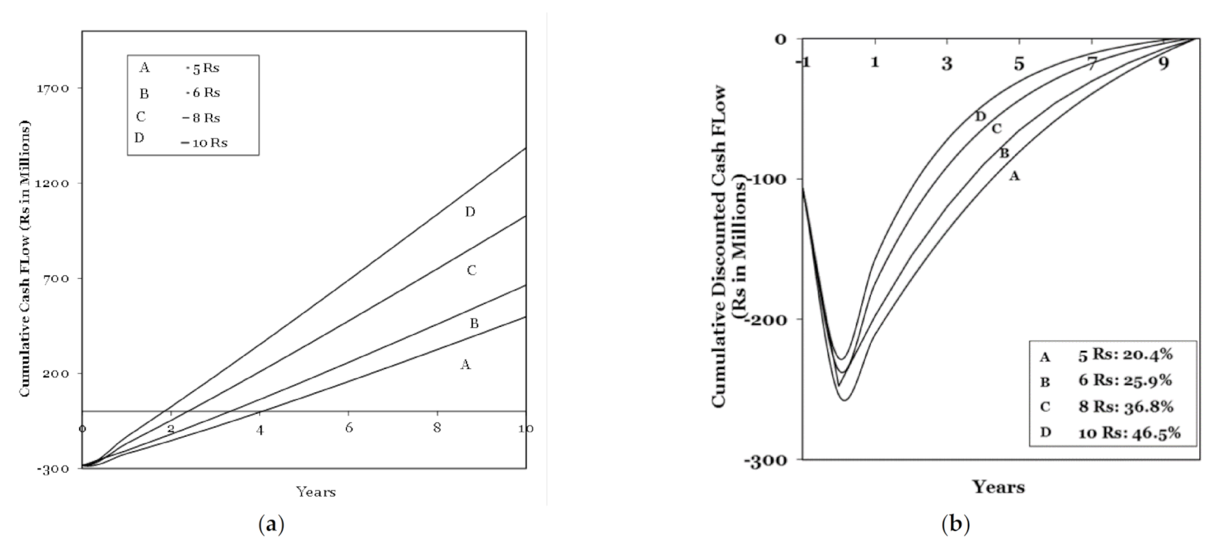
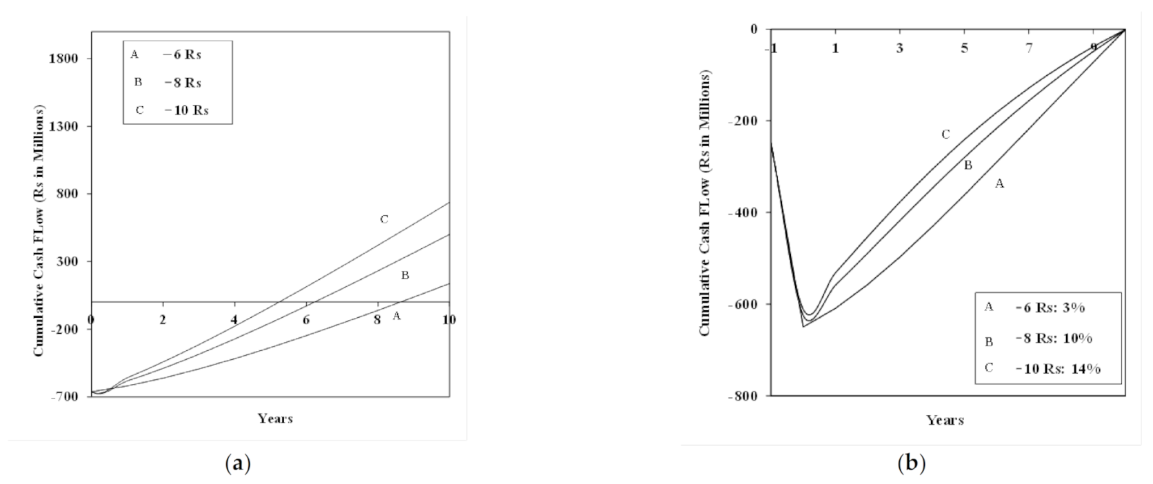
41] performed a techno-economic optimization of SCPPs for 12 designs, the power generation ranging between 5–200 MW. Three different designs of solar chimneys were chosen, namely, the conventional chimney, sloped collector chimney and floating chimney. The author concluded from his analysis that floating chimney design would provide a very short payback period and low initial costs as compared to the other two chimney designs. The analysis showed that for a 100 MW power plant, the payback period was 4.29 years with a floating chimney type, while it was as high as 23.47 and 16.88 years for a conventional chimney and sloped chimney, respectively.
Guo et al. [45] developed a theoretical model based on the hourly meteorological data and heat stored in the soil. Annual power generation predictions of SCPP were obtained using this model and the data. The authors also performed an economic analysis for a 10 MW SCPP. The annual power generation of a 10 MW SCPP was given as 40.22 GWh. The authors predicted a low LCOE of 0.4178 Yuan/kWh, which makes it competitive with wind power and solar photo voltaic cells.
Ali [46] performed optimization studies using a genetic algorithm. An integrated energy system consisting of SCPP combined with warm air from the condensers injected under the turbine of the CSCPP was used in the study. The authors carried out a parametric study focusing on exergo-economic and environmental aspects. Diurnal estimates of the exergy efficiency, net power output and costs associated were estimated. The parametric study performed by the authors suggested that the exergy efficiency and total estimated cost were higher during the night, while power outputs were higher during the day. A further decrease in CO2 emissions was observed with an increase in solar irradiation (decrease in the range of 2.4 and 3.6 t/MWh at different turbine inlet pressures). The authors predicted that in the most favorable conditions, the exergy efficiency would be 7.56%, the total cost rate 406.8 $/h and the CO2 emissions 2.053 t/MWh, which shows a significant environmental impact and energy usage. This study performed by the authors can be utilized to combine other energy systems.
Elsayed and Nishi [42] carried out feasibility studies of a solar chimney (which the authors named Solar Thermal Wind Tower (STWT)) to estimate the economic and environmental impacts. The authors concluded that the cost per unit of electricity was inversely proportional to the capacity of plants. Hence, for sustainable plants, capacities above 100 MW are recommended. Furthermore, the authors concluded that the overall initial investments highly depended on the collector cost. Based on their analysis, the authors predicted positive environmental effects during the manufacturing stage of the plant.
Jamali et al. [43] used the solar photovoltaic panels as a collector roof for enhancing panel cooling (which the authors termed a solar chimney cooled semi-transparent photovoltaic power plant). The authors performed investigations on the thermal and economic aspects. They developed a mathematical model and validated the results using experimental studies from the available literature. Furthermore, the authors carried out an economic assessment of the proposed system for five different cities in Iran. First, the sensitivity analysis of various parameters, such as chimney height, chimney diameter and packing factor (ratio of the area covered by the photovoltaic cells to the area which is blank), was performed to see the effect on power generation and economic performance. The authors observed that the packing factor is a major factor which determines the economic performance. As per the analysis by the authors, the packing factor should be in between 0.3 to 0.5 to get the lowest payback period.
Abdelsalem et al. [40] carried out optimization studies and economic analyses for the installation of a solar chimney power water distillation plant (SCPWDP) in Jordan. A mathematical model was developed and validated. The authors claimed that around 480 MWh of electricity and 124 kTon of distilled water can be produced simultaneously on an annual basis. The LCOE for the plant was 1.86 $/kWh. The sensitivity analysis showed that increasing the chimney height would increase the production of electricity and decrease the LCOE. However, as per the authors, increasing the chimney height caused only marginal improvements.
Zuo et al. [
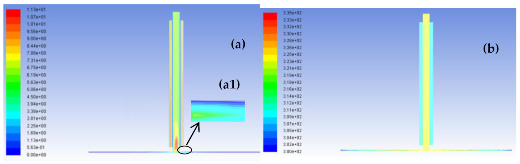
44] presented the concept of SCPP with wind supercharging (which they abbreviated as WS-SCPP). In this system, wind energy at the top of the chimney in an SCPP is utilized in rotating the wind turbine and electricity is generated. The authors carried out mathematical modeling using CFD and an economic analysis. The authors found that the velocities, mass flow rates of air and shaft power in WS-SCPP are higher than those in SCPP. The authors predicted an ~51% increase in the power output at a fixed speed of 100 rpm. The authors emphasized the fact that this concept helps reduce the height of the chimney to get the required power output. For example, increasing the chimney height of an SCPP might improve its output. The authors performed a cost analysis and reported a decrease of 20.1% in cost using a WS-SCPP as compared to a CSCPP.
The literature review suggests that various attempts have been made experimentally, and numerical and analytical models have been used for the implementation of SCPP for power plants. Though considerable research has been carried out based on the data generated from the Manzanares prototype, the experimental focus has now shifted to smaller bench scale prototypes due to the cost involved in building the pilot plants. The numerical works, on the other hand, have been carried out to focus on the design modifications for large-scale power plants (similar to ones of Manzaranes) in an attempt to improve the efficiencies of solar chimneys or to create hybrid systems. On the aspect of technoeconomic feasibility, efforts have been made to show how solar chimneys can play a major role in the environmental impact in terms of the cost benefit. The technoeconomic feasibility has, however, remained focused on large-scale plants. Efforts have been made to determine the techno-economic feasibility of SCPPs, with a focus on various regions in the world, i.e., China, Europe, Iran, Tunisia and the USA.
The literature review also revealed that the major challenge lies with a high-power generating SCPP (~100 MW) with high height (1000 m) and collector diameter (~4500 m), the feasibility of which needs a chimney with a high life span. Low power generating plants (10 MW) have shown good promise. While the design modifications using numerical works have shown that the power output may increase by ~360% [9], the experimental works on small-scale SCPPs [17] can be used for household electricity uses.

3. Objective of the Present Work and Approach

Research work focusing on how one can recirculate air naturally back to a collector and get higher power output was not found in the literature. Incidentally, a mathematical model focusing on the recovery of energy had been proposed by Dai et al. [47] nearly two decades ago, but no other work has focused on it since. Furthermore, no work has been carried out to propose a feasibility/technoeconomic study in the Indian context.
The present article has two major objectives: First, we need to come up with innovative ways to use recirculation air to enhance the power output of a CSCPP; Second, we need to perform technoeconomic feasibility in the Indian context with a focus on providing a good quality of life to people in rural areas.
The first objective focuses on the modified configuration of SCPPs following a mechanism by which the air from the top of the chimney is sent to the space between the collector and the ground (near to turbine), resulting in an increase in the power output. To accomplish the first objective, a robust validated model is required. The authors plan a systematic approach towards this objective. First, an energy balance would be performed across the systems considered (existing and modified). Then, numerical simulations would be performed (for small-scale geometries (Ghalamchi et al. [15]) and the predicted temperature and velocity profiles would be validated against the experimental data. Furthermore, numerical simulations for conventional SCPP (dimensions of Manzanares prototype) would be performed and the results of the temperature profiles and flow patterns would be compared with prominent numerical works (from the study of Ganguli and Deshpande [14]) available in the literature [6,7,26,48,49]. After model validation, different innovative designs of modifications in CSCPP focusing on recovery of energy by recirculating air would be proposed. The proposed modified configurations of SCPP would be simulated with the methodology adopted for the validated model.
To accomplish the second objective, the techno-economic feasibility in an Indian context for a 5 MW CSCPP were carried out. An important aspect while carrying out the technoeconomic feasibility is to consider farm lands for the land required for solar chimneys. Furthermore, the economic analysis would incorporate ways and means for providing free electricity to villagers who would provide their land for the power plant. The land can also be used for cultivating crops during power plant operation. The authors feel that by including the aspect of free electricity provided to villagers, the economic analysis considers good environmental impacts as well as a means of providing the basic necessities to the people living in the rural areas.

4. Chimney Configurations

4.1. Conventional Solar Chimney Power Plant (CSCPP)

A conventional chimney with the same dimensions as that of the Manzanares prototype were chosen for the CFD simulations. The CSCPP will be referred to as Configuration I henceforth in the text. As already illustrated in the introduction section, Figure 1 shows the schematic of this configuration. The working principle has already been described in our previous work by Ganguli and Deshpande [14]. The chimney dimensions are given in Table 4. The properties of the collector are listed in Table 5 while the properties of the fluid (air) are listed in Table 6.
Table 4. Chimney dimensions and heat parameters for all three configurations.
ParametersDimensions (m) for Configuration IDimensions (m) for Configuration IIDimensions (m) for Configuration III
Chimney Height194.6194.6194.6
Chimney Diameter101010
Height of collector above the ground1.851.851.85
Annular gap for recirculation-52.5
Potential Head above gap-25 25
Collector diameter250250250
Heat loss coefficient101010
Transmittance0.30.30.3
Absorptivity0.2170.2170.217
Turbine efficiency0.80.80.8
Collector efficiency0.320.320.32

4.2. Modified Solar Chimney Power Plant (MSCPP)

The modified versions of the SCPP hypothesized in the present work are shown in Figure 2a,b. Two modifications have been suggested in the present work. The modified versions are termed Configurations II and III, as shown in Figure 2a,b, respectively.
Suction is developed in Configuration II due to the temperature difference between the hot air inside the chimney and the cold air in the gap and atmosphere. Due to natural convection, the cold air from the chimney top would flow downwards and leave the bottom of the chimney. The exhaust air can be used for other purposes, such as running electrical devices, if velocities are sufficiently high. At present in our numerical simulations, we assume that the exhaust air goes out to the atmosphere. As shown in Figure 2a, the modified model consists of a concentric pipe with a diameter (D2) higher than that of chimney D1 (referred to henceforth as the annular gap) surrounding the chimney. The gap is assumed to be constructed with reinforced concrete. The notations for the system and the flow through the MCSCPP shown in Figure 2a. Cold air from the atmosphere is sucked into the annular gap and goes out to the base of the chimney at (8) (as shown in Figure 2a).
As shown in Figure 2b, in Configuration III, the cold air flow from the atmosphere that is sucked in due to the natural draft is actually sent inside to the elevated region between the ground and the collector through a channeled pathway. The horizontal distance of this pathway has an optimum distance from the center. This optimum distance from the center of the chimney was found to be one third of the collector diameter for the Manzanares Chimney prototype. The flow is used to enhance the power output by increasing the total flow rate. However, care needs to be taken that there is no buildup of air, and hence, proper instrumentation needs to be made where the mass of air going in is equal to the mass going out.

5. Mathematical Modeling

5.1. Assumptions

  • The collector has uniform temperature distribution.
  • Mass flow rate of air is uniform in the space between the collector and the ground in the case of CSCPP.
  • For modified SCPP, all the air or a certain percentage of air needs to be recirculated.
  • The effect of the wind velocity is neglected.
  • The density variation of air due to the temperature is incorporated through Boussinesq approximation. The buoyancy term in the momentum equation is expressed as: ρ ρ a g = ρ a β T T a .
  • It is assumed that there exist negligible velocity and temperature gradients axially in the solar collector and along the cross section of the chimney.
  • Wall resistance to heat transfer across the collector is ignored. i.e., a negligible temperature difference exists along the collector material.
  • Air in the chimney flows adiabatically.
  • The temperature of the ground is equal to the average air temperature in the space between the collector and the ground.
  • Constant viscosity and specific heat of air.
  • An isentropic process is assumed at the turbine and compression stage.
  • An appropriate design arrangement is made in Configuration III in the chimney base by incorporating a nozzle so that the air coming from the top hits the bottom space with higher velocity than the air velocities from the sides.

5.2. Boundary Conditions

The boundary conditions for Configuration I are provided in Table 7 For Configuration II, the velocity inlet boundary condition is given at the gap inlet (top of chimney) and the pressure outlet at the gap outlet (bottom of chimney). For Configuration III, the velocity inlet boundary condition is similar to Configuration II.

5.3. Mesh Details

In the present work, the 3D geometry of the full-scale conventional chimney with dimensions of the Manzanares prototype has been created in Ansys Workbench 14. The grid sizes are slightly lower than our earlier work due to a difference in the collector area. Three different meshes were considered, namely 416,620, 481,744 and 571,959 cells. The hexahedral mesh was generated for the entire geometry with fine mesh near the walls. The grid sensitivity, which was similar to the one in our previous work [14], was carried out using the velocity profile at the start of the chimney. Little differences in the centerline velocity profiles at the chimney inlet were noticed and a mesh of 481,744 grid cells was selected for Configuration I. For Configuration II, the grid selected had 506,280 grid cells, while for Configuration III, the grid had 668,277 grid cells due to having finer grid cells for the regions near the arrangement for the recirculation.
Table 5. Properties of the collector.
ParametersDimensions
Density (kg/m3)2200
Viscosity (kg/m/s)106
Thermal conductivity (W/m K)1.4
Absorption Coefficient (m−1)0.04
Refractive Index1.45
Scattering Coefficient (m−1)0.01
Specific Heat (J/kg K)840
Table 6. Ambient fluid properties.
Sr No.Property NameValue
1Dynamic viscosity1.85 × 10–5 Ns/m2
2Thermal conductivity0.026 W/mK
3Specific heat1006 J/kg K
4Density1.184 kg/m3
Table 7. Boundary conditions for all configurations.
Sr No.LocationDescription
1Chimney inletPressure = 0 Pa, Temperature = 300 K
2CollectorH = 10 W/m2; T = 300 K
3Chimney outletHeat Flux, q = 0; P = 0 Pa
4Chimney wallsAdiabatic, Heat flux q = 0 W/m2
Since the geometry and mesh are similar to our earlier work [14] on conventional SCPPs, we show only the geometry and mesh of Configurations II and III in Figure 2a,b, respectively.

5.4. Grid Sensitivity

In the present work, the cylindrical chimney geometry of the full-scale geometry of the Manzanares prototype (CSCPP or Configuration I) and the modified configurations were chosen. The geometry and hexahedral mesh are similar to the ones of Ganguli and Deshpande [14], and hence, have not been reproduced in the present work. The grid independence was investigated for all the three configurations. A sample grid sensitivity of the CSCPP is shown in Figure 3. Three different grid cases, i.e., (a) 416,640, (b) 481,744, and (c) 571,959, were considered for Configuration I. The grids were distributed between uniform and non-uniform grids. Zones where the velocity and temperature gradients were high were meshed with non-uniform grids (~35%), while the rest of the region (~65%) was meshed with uniform grids. The Yplus in the wall region of the chimney was kept around 25 to capture the effect of turbulence near wall. Minor differences were observed between 481,744 and 571,959. However, these were found to be within the 3% average error; hence, 481,744 grids were used for Configuration I. A combination of hexahedral and tetrahedral mesh was applied for the two configurations. The geometry and mesh of the two configurations are shown in Figure 4a–d.

5.5. Method of Solution

Simulations have been carried out using commercial flow simulation software ANSYS FLUENT 14. The RNG k-ε turbulence model with a standard wall function was used for the turbulence associated with the flow. Residuals for various quantities were fixed as follows:1 × 10⁻³ for continuity, 1 × 10⁻⁴ for momentum, 1 × 10⁻⁶ for energy equations and 1 × 10⁻⁵ for turbulence equations. The under-relaxation parameters used for the set of variables are as follows: 0.3 for pressure equation; 0.7 for momentum equations; 0.8 for turbulence equations; 0.8 for energy equation; 1 for density, energy and body forces. In this study, a segregated solver was employed for obtaining the solution of the momentum equations. A Second Order Upwind numerical scheme was used for the momentum, energy and turbulence equations, while for the pressure equation, the PRESTO scheme was used.
Figure 5 shows a typical convergence plot for the CSCPP simulation. For configuration II, the following approach was followed. First, the conventional chimney was activated with minimal velocity in the gap and a converged solution was obtained. The average velocity of the chimney near the start of the gap has been given as a velocity inlet boundary condition. The entire geometry was then simulated. The geometry used for the simulation was kept simple due to restrictions of computational power and full-scale simulation. A solid zone has been kept to represent the wall between the gap and the chimney. The properties of the wall are taken as that of Reinforced Concrete. Similarly, for Configuration III, the solid zone has been kept for the gap as well as the geometry inside the collector area arrangement.

6. Analytical Modeling

6.1. Analytical Model for a Conventional Chimney

Dai et al. (47) presented an energy balance of a conventional solar power plant:
Q = m C p T
Heat   can   also   he   expressed   as   Q = τ α A c o l l G β T a A c o l l   ( a   represent   ambient )
In   terms   of   collector   efficiency   it   can   be   expressed   as   Q = η A c o l l G
Mass   flow   rate   is   expressed   as   m = ρ A c v c   ( c   represents   chimney )
v c = τ α A c o l l G β T a A c o l l ρ A c C p T
The   efficiency   of   solar   collector   is   given   by :   η c o l l = τ α β T a G
T = 2 Q A c β F R 1 F
F R = 1 1 F + A c o l l β 2 m ˙ C p
F″ is the flow factor and is given as:
F = F R F
The analytical model equations for electrical power, total power and chimney velocity have been taken from Dai et al. [47].
The electrical energy is given by:
P e l e c = 2 3 η c o l l η m e c h g C p T a H s c A c o l l G
The total power contained in the flow is given by:
P t = g H s c T 0 v c Δ T A c h
where:
v c = τ α A c o l l G β A c o l l T a ρ a A c h C p T
The temperature difference (∆T) is the one between the ground and the collector while (∆Ta) is the difference between the heat absorption layer and the ambient air.

6.2. Analytical Model for Configurations II and III

For Configurations II and III, the energy balance has been modified and the model developed has an addition term for heat taken up by recirculated air in the annular gap (also termed recirculation air henceforth). Hence, the modified heat flux would be:
Q ˙ = m ˙ C p Δ T r a d i a t i o n + m ˙ C p Δ T r e c i r c u l a t i o n
For Configuration II, the chimney velocity is given by:
V c = τ α A c o l l G β Δ T a A c o l l + U A c h Δ T a ρ a A c h C P Δ T + H s c ρ a g
For Configuration III, mass balance is as follows:
m ˙ t o t a l = m ˙ c h + m ˙ r e c i r c
m ˙ t o t a l = ρ a A c h v c
where m ˙ t o t a l is the total mass flow in the chimney. The gap is the cross-section area of the annulus between the main chimney (Diameter, D1) and the concentric chimney (Diameter D2) surrounding it. Presently, the diameter of the annulus is taken to be the hydraulic diameter.
Let m ˙ recirc be the cold flow from the atmosphere, which can be assumed to be a certain percentage (x%) of the total flow. Then, Equation (15) becomes:
m ˙ recirc = xm ˙ ch
m ˙ total = 1 + x m ˙ ch
The final velocity of the chimney, combining Equations (16) and (18), is then:
v c = m ˙ total ρ a A ch
It was found that when 60% of the fresh air of the total flow (going out at top of chimney) is sucked from the atmosphere, the velocity was found to be around 14.5 m/s; the normal velocity was 8.5 m/s for the Manzanares prototype with a certain solar radiation and ambient temperature. The chimney efficiency is given by:
η S c = P t o t Q ˙
A proper arrangement needs to be made to make sure that there is no build-up of air (as mentioned in Section 4) and purge streams or geometrical modifications might be essential. For modeling simplicity, suitable assumptions have been made and boundary conditions have been applied, as discussed in Section 5.2.

7. Techno-Economic Analysis

In the literature review of the techno-economic analysis, the importance of solar power in India has been highlighted. For the current scenario, we have carried out the techno-economic analysis for a 5 MW SCPP, describing the initial investments needed and carrying out a Discounted Cash Flow (DCF) analysis for two different cases: one assumes low investment costs due to government subsidy and the other assumes actual investment costs assuming no government subsidy.

7.1. Initial Investment

The initial investment of the SCPP consists of the costs of the chimney, the collector, land, labor and the turbine and its accessories. Researchers [19,34] have considered the costs to fall into three major categories, i.e., the chimney cost, the collector cost and the Power Consumption Unit (PCU) cost. In the present work, two cases were considered: Case I, in which subsidy is provided by the government, and Case II, in which no subsidy is provided by the government. The size of the SCPP considered for the techno-economic analysis is given in Table 8, while the costs for the chimney, collector and PCU for both subsidized and not-subsidized cases are given in Table 9. The detailed costs of the initial investment are provided in Table 10, while the operating costs are provided in Table 11. The chimney material is assumed to be made of Reinforced Concrete Cement (RCC) and the cost is assumed from the linear extrapolation of a chimney that is 60 m [50] to 300 m high. An appropriate cost index was applied to calculate the cost for the present year. The linear variation of the wall thickness from the base to the top of chimney was considered, as per Wakchaure et al. [50].
Table 8. Dimensions of the chimney for the techno-economic analysis.
ParametersDimensions (m)
Collector Diameter1000
Distance from ground to cover3
Chimney height300
Chimney diameter30
Table 9. Capital Cost for the SCPP for the techno-economic analysis.
Sr No.ItemWith SubsidyWithout Subsidy
Rs. (in million)% total costRs. (in million)% total cost
1Collector20070.422540861.63
2Chimney3411.9718548.16
3Power Conversion Unit5017.605620030.21
Total 284100662100
Table 10. Initial investment costs for the SCPP for the techno-economic analysis.
Cost TypeSubsidized Cost
(Rs. Per sq ft)
Without Subsidy, (Rs. Per sq ft)
Cost of collector material (FRP) 1 mm thick (Rs. per sq ft)513
Turbine and accessories costs (million Rs)50200
Labor cost (million Rs)48
Land cost (million per day)31.38431.384
Chimney Construction cost (million Rs)1010
Table 11. Operating costs for the SCPP for the techno-economic analysis.
Cost TypeCost (Rs. In Lacs)
Maintenance Cost3
Labor Cost2
Miscellaneous costs6
Total11.00
The collector is considered to consist of a carbon steel support matrix and a transparent roof made of Fiber Reinforced Plastic (FRP), 1 mm thick. Though glass is a preferred material in terms of its resistance to storms and rains, presently, FRP is often used because of its low cost and high durability as per the service life. The design theory of the turbines for the SCPP is usually adapted from that of gas or wind turbines [51]. The cost of the turbine has been considered from the IRNE report [52]. For the land cost, the following assumptions were made: 1. The land would be agricultural land legally acquired from the farmers/land owners who would grow their crops on the land. 2. A cost of Rs 1 per sq ft would be given to the farmers/land owners. 3. Free electricity would be provided to the farmers/land owners. For both with and without subsidy scenarios, the major cost is that of the collector (60–70%), while the PCU unit would comprise around 18–30% of the cost and the construction of the chimney, land and labor cost would comprise around 8–12% of the total cost.

7.2. Profit, Loss and Discounted Cash Flow (DCF) Analysis

Table 12 shows the economic parameters used for the analysis. Currently, we considered that the benefit received from the SCPP is the revenue from selling electricity. Let R represent the generated revenue, E the total electricity output and Ps the price of solar electricity; then, the generated revenue after n years is given by:
R = E × P s
Expenses other than capital investment involve the interest rate (i) on the debt taken in the form of bank loans and income tax on profit before tax (PBT). The total cost was divided in the first two years, in which 66% of the capital is used in the first year and 33% is used in the second year. It was assumed that the debt-to-equity ratio is 3:2. Hence, 66% of amount was taken as debt and 33% as equity. The interest rate was taken as 22% on debt and 35% on income tax. As discussed in Section 2.2, a 500 MW solar power plant can be completed in 18 months. Hence, it was considered that the present power plant would be completed in 10 months and the revenue for the first year would generate 10% of the total revenue. The operating cost was considered as 1.25% of the capital cost for the first two years, since in the first two years, the plant runs at 10% and 50% of its capacity.
Table 12. Economic Parameters.
ParameterValueUnit
Interest rate on loans22%
Income tax rate35%
Debt67%
Equity33%
Service life12Years
Initial investment (With subsidy)284Rs. million
Initial investment (Without subsidy)662Rs. million
Annual Electricity Generation14.8GWh/annum
After the first two years, (capacities being 10% in first year and 50% in second year), the plant would run at its full capacity and the operating costs would be 5% of the capital costs. The following procedure is followed for the Discounted Cash Flow Analysis:
  • Calculate the Total revenue for each year using Equation [19];
  • Calculate the Gross Profit (PG) for each year, such that PG = PR−CO;
  • Calculate the Profit before tax (PBT) = PG-IDB;
  • Calculate the Profit after tax (PAT) = PBT−T;
  • Calculate the Cash Flow (Cf) = PAT + CT;
  • Calculate the Discounted Cash Flow (DCF) CDCF= Cf (1 + iR)−j;
  • Calculate the Cumulative Discounted Cash Flow (CDCF) CCDCF= CDCF(j) + CDCF (j + 1);
where j is the number of years j = 1, 2, 3….., n.
We did not take into account the benefits of carbon credits and the benefits from the vegetation in our cost calculations.

8. Results and Discussion

In this section, the velocity and temperature patterns for all the three configurations, i.e., I, II and III, are discussed. Furthermore, a techno-economic analysis of the conventional chimney design considering the two cases discussed in Section 6 is performed. We restrict ourselves to temperature patterns of the conventional and modified chimney.

8.1. Model Validation

The CSCPP/Configuration I has been validated with the temperature profile of the prototype presented by various researchers [6,26,48,49]. A CFD model of the experimental facility of Ghalamchi et al. [15] (which is relatively much smaller than the Manzanares prototype) was developed and validated against the experimentally developed temperature and velocity profiles. Figure 6a,b shows the comparison of the velocities of the model prediction and experimental data. The model predicts well up to a distance of 0.4 m from the chimney, after which it shows a deviation of 5–7%.
The temperature profiles show a deviation of around 5% compared to the experimental data. The predictions are comparable with the predictions of Singh et al. [9]. Figure 7 shows the temperature profiles for the Manzanares prototype, which was compared with the predictions of different authors. The present model predictions match well with the predictions of Ming et al. [49], with a deviation of around 7%. In Figure 8, the maximum velocity magnitudes, obtained experimentally by Haaf et al. [53], are compared with those obtained by the analytical model of Dai et al. [47] and the CFD simulations of the present work for Configuration I. Good agreement was observed between the CFD predictions and experimental data of Haaf et al. [53] for Configuration I, with a deviation of 6%. Similarly, for Configurations II and III, the analytical model predictions (analytical model of present work) and CFD predictions are compared. A good agreement between the analytical model predictions and CFD model predictions are observed with a maximum deviation of 10%.

8.2. Flow, Temperature Patterns and Pressure Drop

The velocity and temperature contours of Configuration I are shown in Figure 9a,b. The velocity contours clearly predict the maximum velocity at the start of the chimney and the end of the collector. This is depicted by the plume-like structure at the center. The predicted velocity is 8.34 m/s, which is similar to the velocity of 9 m/s from the experimental data of Haaf et al. [53] and the one predicted by the present analytical model for the conventional chimney, which is a model from Dai et al. [47]. The predicted temperature is around 305 K, which is similar to the one predicted by Ming et al. [49] for the same geometry.
For Configuration II, Figure 10a,b show the velocity and temperature contours.
The assumption here is that the gap between the two concentric cylinders (the chimney and the outer pipe) is around 5 m and that all the cold air was sucked out due to the natural draft into the gap. The patterns are similar to Configuration I, with max velocities of 9.5 m/s, which is a slight rise compared to the conventional geometry. The temperatures for the conventional geometry are around 323 K, which is much higher than that predicted for Configuration I. Figure 11a,b shows the velocity and temperature contours for Configuration III. The velocity contours show that the max velocities are around 15.5, which is around 85% higher than that of Configuration I, while the temperature contours have a uniform value of 311 K throughout the chimney.
An enlarged view of all three configurations in the region between the ground and the collector, which is near the collector center, is shown in Figure 9a, Figure 10a and Figure 11a. It can be observed that the flow patterns in 9a and 10a are similar (as shown in A1 of both figures). However, due to the channeled pathway (shown in Figure 2b), the flow patterns are different in Figure 11a. The channel forms a hindrance to the passage to the air (as shown in a1 and a2). This increases the overall velocity of the air when it reaches the collector exit or the node where the turbine is placed.
The pressure drop is a very important criterion for any SCPP. The static pressure is lowest at the bottom of the chimney and center of the collector, where the air enters from the collector to the chimney. We have performed a pressure drop analysis for all three configurations. The pressure drop for Configuration I and II was found to be 5 Pa, while for Configuration III, it was found to be 6.5 Pa; thus, the pressure drop value is 1.5 Pa higher for Configuration III.

8.3. Techno-Economic Analysis

Figure 12a and Figure 13a show the results of the sensitivity analysis of the effect of the selling price of the chimney on the cash flow in the scenarios with subsidy and without subsidy, respectively. The increase in the selling price of electricity decreases the payback period and also increases the rate of return (ROR) at subsidized fixed capital cost or initial investment. The Levelized Cost of electricity (LCE) comes to around Rs 8 per kWh and the payback is 2.5 years. The rate of return is 36.8% in this case. Figure 12b shows the discounted cash flow (DCF) with increasing discounted rate of return in line with the increase in price per unit of electricity charged. The optimum discounted rate of return is found to be 25.9% and the price per unit of electricity charged is Rs 6 per kWh. Figure 13a shows the effect of an increase in the selling price of the chimney on the cash flow without subsidy. The Levelized cost of electricity (LCE) comes to around Rs 10 per kWh and the payback period is 5 years. Furthermore, Figure 10b shows that DCF has a similar trend as Figure 12b, but the optimum discounted rate of return is 14% and the price per unit of electricity charged is Rs 10. This clearly suggests that if subsidized rates for initial investments are not provided, other alternatives, such as increasing the service life or modifications in the chimney for increased power output, would be required. Another option is simultaneously building multiple SCPPs at different locations, which would increase revenue generation.

9. Conclusions

The following overall conclusions can be drawn. CFD simulations have been carried out for the Manzanares prototype and compared with the experimental results of Haaf et al. [53]. The temperature profiles were compared with different models for the same geometry in the literature and a good agreement was seen with the model of Ming et al. [49]. Hence, these validated model settings were used for further CFD simulations for geometric modifications. The small-scale geometry used by Ghalamchi et al. [15] was also simulated, and good agreement was observed for the experimental and predicted data.
CFD simulations for the modifications in a conventional SCPP by directing cold flow from the atmosphere from the top to the bottom of the chimney have been carried out with certain assumptions. This type of arrangement can be coupled with other energy-producing devices. An analytical model has been developed and velocity magnitudes at the collector exit were in good agreement with the predicted results of the CFD simulations.
CFD simulations for the modified geometry for a conventional SCPP have also been carried out with certain assumptions. It has been observed that the velocities increased by 85% in this arrangement, which would have a significant improvement in the power output. An analytical model has been developed, and the model showed good agreement with CFD simulations.
The techno-economic feasibility of the conventional SCPP was carried out for two cases: (a) subsidized initial investment and (b) unsubsidized initial investment. It was found that for an LCE of Rs 6 per kWh in the subsidized case, the payback was around 2.5 years, while for an LCE of Rs 10 per kWh in the non-subsidized case, the payback was around 5 years.
Alternative ways to reduce the LCE need to be considered if subsidies on materials and power consumption units are not available. Options include increasing the service life and modifications in the chimney geometry for increased power output. Multiple SCPPs at different locations would be another option to increase revenue generation.

10. Future Work

Future work should include minimizing the assumptions made for the modified geometries and building an integrated CFD model for Configuration III to substantiate our current findings. Furthermore, different modifications, such as a divergent collector, a divergent chimney, use of the wind energy and use of heat energy for the generation of additional power apart from the power generated by solar chimneys, need to be performed. The use of photovoltaic cells as a collector surface, among others, needs to be integrated in the CFD model. A techno-economic analysis that includes carbon credits with modified SCPP would be taken up for higher service life and optimized payback periods. Furthermore, a sensitivity analysis of geometric parameters of integrated models needs to be performed before the analysis.

Author Contributions

Conceptualization, S.S.D. and A.A.G.; methodology, A.A.G.; software, validation, A.A.G.; formal analysis, A.A.G. and S.S.D.; investigation, A.A.G.; resources, A.B.P.; data curation, A.A.G.; writing—original draft preparation, A.A.G.; writing—review and editing, A.A.G.; visualization, A.A.G.; supervision, A.B.P.; project administration, A.B.P.; funding acquisition, A.B.P. All authors have read and agreed to the published version of the manuscript.

Funding

This research received no external funding.

Data Availability Statement

Not applicable.

Acknowledgments

The authors A.A.G. and S.S.D. would like to acknowledge the facilities and resources provided by Institute of Chemical Technology during this work.

Conflicts of Interest

The authors declare no conflict of interest.

Abbreviations

Abbreviations
CDCFCumulative Discounted Cash Flow
DSCDiffuser Solar Chimney
DISCDiffusing Inlet Solar Chimney
DOSCDiffusing Outlet Solar Chimney
DCFDiscounted Cash Flow
LCELevelized Electricity Cost
LCOELevelized Cost of Electricity
SCPPSolar Chimney Power Plant
CSCPPConventional Solar Chimney Power Plant
Notations
AgapArea of the annulus between the two concentric chimneys, (m−2)
AcCross-sectional area of the solar chimney (m2)
AcollSolar collector area (m2)
CCost, Rs (INR)
CfCash Flow, Rs (INR)
CoOperating cost Rs (INR)
C P Specific heat of the fluid (kJ m−2)
DCollector Diameter (m)
D1Chimney diameter (m)
D2Diameter of Outer chimney where D2-D1 is annular gap, (m)
EExpenditure, Rs (INR)
FRHeat removal factor, (-)
FEfficiency factor of the solar collector
FFlow factor, (-)
GSolar irradiance (W/m2)
GGravitational constant (m s−2)
HHeight of the chimney (m)
H1Height above the gap, (m)
hscHeat transfer coefficient, (Wm−1 K)
m ̇ Mass flow rate (kg s−1)
NNumber of years of service life
PATProfit after tax, Rs (INR)
PBTProfit Before Tax, Rs (INR)
PGGross Profit in Rs (INR)
PRRevenue generated, Rs (INR)
PelecMechanical power of the turbine (W)
PtTotal power or useful energy contained in the flow (W)
PsPrice of solar electricity, Rs (INR)
RRevenue generated, Rs (INR)
TTemperature (K)
T0Ambient temperature (K)
T Temperature rise between the collector inflow and outflow (°C)
T a Temperature difference between the heat absorption layer and the ambient air (°C)
tTime (s)
U Overall heat transfer coefficient (W m−2 K−1)
uVelocity component (m s−1)
vcVelocity at the end of the collector and the start of the chimney
vgapVelocity inside the gap, m s−1
Greek symbols
β Thermal expansion coefficient (K−1)
η coll Solar collector efficiency
ηmechMechanical efficiency of turbine
τ α Effective product of the transmittance and absorbance
ρ Density of the fluid (kg m−3)
Δ Difference in a quantity, e.g., temperature
μ Kinematics viscosity (m2 s−1)
Subscripts
aAir
chChimney
elecElectrical
fCash flow
GGross
gapAnnulus between two concentric chimneys
jYear for which the cash flows are to be calculated
OOperating cost
RRate of the return or generated revenue
recircRecirculation
scSolar chimney
totalTotal mass flowrate
turTurbine

References

  1. Schlaich, J. The Solar Chimney: Electricity from the Sun; Axel Menges: Geislingen, Germany, 1995. [Google Scholar]
  2. Kasaeian, A.B.; Molana, S.; Rahmani, K.; Wen, D. A Review on Solar Chimney Systems. Renew. Sustain. Energy Rev. 2017, 67, 954–987. [Google Scholar] [CrossRef]
  3. Why Are Indians Paying Three to Four Times the Cost of Generating Electricity? Cost of Electricity in India. 2020. Available online: https://www.nationalheraldindia.com/india/why-are-indians-paying-three-to-four-times-the-cost-of-generating-electricity (accessed on 21 May 2021).
  4. How India in a Short Period of Time Has Become the Cheapest Producer of Solar Power. 2019. Available online: https://economictimes.indiatimes.com/small-biz/productline/power-generation/how-india-in-a-short-period-of-time-has-become-the-cheapest-producer-of-solar-power/articleshow/70325301.cms?utm_source=contentofinterest&utm_medium=text&utm_campaign=cppst (accessed on 21 May 2021).
  5. Al-Kayiem, H.H.; Aja, O.C. Historic and recent progress in solar chimney power plant enhancing technologies. Renew. Sustain. Energy Rev. 2016, 58, 1269–1292. [Google Scholar] [CrossRef]
  6. Pasumarthi, N.; Sherif, S.A. Experimental and theoretical performance of a demonstration solar chimney model—Part I: Mathematical model development. Int. J. Energy Res. 1998, 22, 277–288. [Google Scholar] [CrossRef]
  7. Pasumarthi, N.; Sherif, S.A. Experimental and theoretical performance of a demonstration solar chimney model—Part II: Experimental and theoretical results and economic analysis. Int. J. Energy Res. 1998, 22, 443–461. [Google Scholar] [CrossRef]
  8. Hu, S.; Leung, D.Y.C.; Chan, J.C.Y. Numerical modelling and comparison of the performance of diffuser-type solar chimneys for power generation. Appl. Energy 2017, 204, 948–957. [Google Scholar] [CrossRef]
  9. Singh, A.P.; Kumar, A.A.; Singh, O.P. Performance enhancement strategies of a hybrid solar chimney power plant integrated with photovoltaic panel. Energy Convers. Manag. 2020, 218, 113020. [Google Scholar] [CrossRef]
  10. Fadaei, N.; Kasaeian, A.; Akbarzadeh, A.; Hashemabadi, S.H. Experimental investigation of solar chimney with phase change material (PCM). Renew. Energy 2018, 123, 26–35. [Google Scholar] [CrossRef]
  11. Habibollahzade, A.; Houshfara, E.; Ahmadia, P.; Behzadia, A.; Gholamiana, E. Exergo-economic assessment and multi-objective optimization of a solar chimney integrated with waste-to-energy. Sol. Energy 2018, 176, 30–41. [Google Scholar] [CrossRef]
  12. Ming, T.; Gong, T.; de Richter, R.K.; Liu, W.; Koonsrisuk, A. Freshwater generation from a solar chimney power plant. Energy Conserv. Manag. 2016, 113, 189–200. [Google Scholar] [CrossRef]
  13. Pretorius, J.P.; Kroger, D.G. Solar chimney power plant performance. J. Sol. Energy Eng. 2006, 128, 302–311. [Google Scholar] [CrossRef]
  14. Ganguli, A.A.; Deshpande, S. Three Dimensional CFD Studies of a Solar Chimney: Effect of Geometrical Parameters and Diurnal Variations. Front. Chem. Eng. 2020, 2, 1–15. [Google Scholar] [CrossRef]
  15. Ghalamchi, M.; Kasaeian, A.; Ghalamchi, M.; Mirzahosseini, A.H. An experimental study on the thermal performance of a solar chimney with different dimensional parameters. Renew. Energy 2016, 91, 477–483. [Google Scholar] [CrossRef]
  16. Mekhail, T.; Rekaby, A.; Fathy, M.; Bassily, M.; Harte, R. Experimental and Theoretical Performance of Mini Solar Chimney Power Plant. J. Clean Energy Technol. 2017, 5, 294–298. [Google Scholar] [CrossRef] [Green Version]
  17. Balijepalli, R.; Chandramohan, V.P.; Kirankumar, K. Development of a small scale plant for a solar chimney power plant (SCPP): A detailed fabrication procedure, experiments and performance parameters evaluation. Renew. Energy 2020, 148, 247–260. [Google Scholar] [CrossRef]
  18. Khidir, D.K.; Atrooshi, S.A. Investigation of thermal concentration effect in a modified solar chimney. Sol. Energy 2020, 206, 799–815. [Google Scholar] [CrossRef]
  19. Guo, P.; Wang, Y.; Li, J.; Wang, Y. Thermodynamic analysis of a solar chimney power plant system with soil heat storage. Appl. Therm. Eng. 2016, 100, 1076–1084. [Google Scholar] [CrossRef]
  20. Petela, R. Thermodynamic study of a simplified model of the solar chimney power plant. Sol. Energy 2009, 83, 94–107. [Google Scholar] [CrossRef]
  21. Maia, C.B.; CastroSilva, J.O.; Cabezas-Gómez, L.; Hanriot, S.M.; Ferreira, A.G. Energy and exergy analysis of the air flow inside a solar chimney. Renew. Sustain. Energy Rev. 2016, 27, 350–361. [Google Scholar] [CrossRef]
  22. Mehrpooya, M.; Shahsavan, M.; Mehdi, M.; Sharifzadeh, M. Modeling, energy and exergy analysis of solar chimney power plant-Tehran climate data case study. Energy 2016, 115, 257–273. [Google Scholar] [CrossRef]
  23. Mehdipour, R.; Golzardi, S.; Baniamerian, Z. Experimental justification of poor thermal and flow performance of solar chimney by an innovative indoor experimental setup. Renew. Energy 2020, 157, 1089–1101. [Google Scholar] [CrossRef]
  24. Nia, E.S.; Ghazikhani, M. Numerical investigation on heat transfer characteristics amelioration of a solar chimney power plant through passive flow control approach. Energy Conserve. Manag. 2015, 105, 588–595. [Google Scholar] [CrossRef]
  25. Liu, Q.; Cao, F.; Liu, Y.; Zhu, T.; Liu, D. Design and Simulation of a Solar Chimney PV/T Power Plant in Northwest China. Int. J. Photoenergy 2018, 1478695, 1–13. [Google Scholar] [CrossRef] [Green Version]
  26. Gholamalizadeh, E.; Kim, M.-H. Three-dimensional CFD analysis for simulating the greenhouse effect in solar chimney power plants using a two-band radiation model. Renew. Energy 2014, 63, 498–506. [Google Scholar] [CrossRef]
  27. Arzpeyma, M.; Mekhilef, S.; Newaz, K.M.S.; Horan, B.; Seyedmahmoudian, M.; Akram, N.; Stojcevski, A. Solar chimney power plant and its correlation with ambient wind effect. J. Therm. Anal. Calorim. 2019, 141, 649–668. [Google Scholar] [CrossRef]
  28. Gholamalizadeh, E.; Mansouri, S.H. A comprehensive approach to design and improve a solar chimney power plant: A special case—Kerman project. Appl. Energy 2013, 102, 975–982. [Google Scholar] [CrossRef]
  29. Okoye, C.O.; Solyali, O.; Taylan, O. A new economic feasibility approach for solar chimney power plant design. Energy Convers. Manag. 2016, 126, 1013–1027. [Google Scholar] [CrossRef]
  30. Bahar, F.A.; Guellouz, S.; Saharaoui, M.; Kaddeche, S. Economic and Cost Effective Analysis of Solar Chimney Power Plants in the South of Tunisia; Fourth Africalis PhD Academy: Hammamet, Tunisia, 2016. [Google Scholar]
  31. Okoye, C.O.; Atikol, U. A parametric study on the feasibility of solar chimney power plants in North Cyprus conditions. Energy Convers. Manag. 2014, 80, 178–187. [Google Scholar] [CrossRef]
  32. Li, W.; Wei, P.; Zhou, X. A cost-benefit analysis of power generation from commercial reinforced concrete solar chimney power plant. Energy Convers. Manag. 2014, 79, 104–113. [Google Scholar] [CrossRef]
  33. Abdelsalem, E.; Kafiah, F.; Alkasrawi, M.; Al-Hinti, I.; Azzam, A. Economic Study of Solar Chimney Power-Water Distillation Plant (SCPWDP). Energies 2020, 13, 2789. [Google Scholar] [CrossRef]
  34. Fluri, T.P.; Pretorius, J.P.; Van Dyk, C.; von Backström, T.W.; Kröger, D.G.; Van Zijl, G.P.A.G. Cost analysis of solar chimney power plants. Sol. Energy 2009, 83, 246–256. [Google Scholar] [CrossRef]
  35. Schlaich, J.; Bergermann, R.; Schiel, W.; Weinrebe, G. Sustainable electricity generation with solar updraft towers. Struc. Eng. Int. 2004, 3, 225–229. [Google Scholar] [CrossRef]
  36. Bernardes, M.A.D.S. Technische, ökonomische und ökologische Analyse von Aufwind-Kraftwerken. Institut für Energiewirtschaft und Rationelle Energieanwendung; Universita¨t Stuttgart: Germany, Stuttgart, 2004. [Google Scholar]
  37. Zhou, X.; Yang, J.; Wang, F.; Xiao, B. Economic analysis of power generation from floating solar chimney power plant. Renew. Sustain. Energy Rev. 2009, 13, 736–749. [Google Scholar] [CrossRef]
  38. Cao, F.; Zhao, L.; Guo, L. Economic analysis of solar chimney power plants in Northwest China. J. Renew. Sustain. Energy 2013, 5, 021406. [Google Scholar] [CrossRef]
  39. Tawalbeh, M.; Al-Othman, A.; Kafiah, F.; Abdelsalam, E.; Almomani, F.; Alkasrawi, M. Environmental impacts of solar photovoltaic systems: A critical review of recent progress and future outlook. Sci. Total Environ. 2021, 759, 143528. [Google Scholar] [CrossRef]
  40. Abdelsalam, E.; Kafiah, F.; Tawalbeh, M.; Almomani, I.; Azzam, A.; Alkasrawi, A.M. Performance analysis of hybrid solar chimney–power plant for power production and seawater desalination: A sustainable approach. Int. J. Energy Res. 2020. [Google Scholar] [CrossRef]
  41. Ali, B. Techno-economic optimization for the design of solar chimney power plants. Energy Convers. Manag. 2017, 138, 461–473. [Google Scholar] [CrossRef]
  42. Elsayed, I.; Nishi, Y. A Feasibility Study on Power Generation from Solar Thermal Wind Tower: Inclusive Impact Assessment Concerning Environmental and Economic Costs. Energies 2018, 11, 3181. [Google Scholar] [CrossRef] [Green Version]
  43. Jamali, S.; Nemati, A.; Mohammadkhani, F.; Yari, M. Thermal and economic assessment of a solar chimney cooled semitransparent photovoltaic (STPV) power plant in different climates. Sol. Energy 2019, 185, 480–493. [Google Scholar] [CrossRef]
  44. Zuo, L.; Qu, N.; Liu, Z.; Ding, L.; Dai, P.; Xu, B.; Yuan, Y. Performance study and economic analysis of wind supercharged solar chimney power plant. Renew. Energy 2020, 156, 837–850. [Google Scholar] [CrossRef]
  45. Guo, P.; Zhai, Y.; Xu, X.; Li, J. Assessment of levelized cost of electricity for a 10-MW solar chimney power plant in Yinchuan China. Energy Convers. Manag. 2017, 152, 176–185. [Google Scholar] [CrossRef]
  46. Ali, H. Employing photovoltaic/thermal panels as a solar chimney roof: 3E analyses and multi-objective optimization. Energy 2019, 166, 118–130. [Google Scholar]
  47. Dai, Y.J.; Huang, H.B.; Wang, R.Z. Case study of solar chimney power plants in Northwestern regions of China. Renew. Energy 2003, 28, 1295–1304. [Google Scholar] [CrossRef]
  48. Pastohr, H.; Kornadt, O.; Gurlebeck, K. Numerical and analytical calculations of the temperature and flum field in the upwind power plant. Int. J. Energy Res. 2004, 28, 495–510. [Google Scholar] [CrossRef]
  49. Ming, T.; Liu, W.; Xu, G. Analytical and numerical investigation of the solar chimney power plant systems. Int. J. Energy Res. 2006, 30, 861–873. [Google Scholar]
  50. Wakchaure, M.R.; Sapate, S.V.; Kuwar, B.B.; Kulkarni, P.S. Cost optimization of reinforced concrete chimney. Int. J. Civil Eng. Tech. 2013, 4, 404–414. [Google Scholar]
  51. Fluri, T.P. Turbine Layout for and Optimization of Solar Chimney Power Conversion Units. Ph.D. Thesis, University of Stellenbosch, Stellenbosch, South Africa, 2008. [Google Scholar]
  52. Anuta, H.; Raylon, P.; Taylor, M. IRENA Report. Renewable Energy Technologies: Cost Analysis Series; International Renewable Energy Agency: Abu Dhabi, United Arab Emirates, 2019. [Google Scholar]
  53. Haaf, W.; Friedrich, K.; Mayr, G.; Schlaich, J. Solar Chimneys Part I: Principle and Construction of the Pilot Plant in Manzanares. Int. J. Sol. Energy 1983, 2, 3–20. [Google Scholar] [CrossRef]
Figure 1. Schematic of configuration I—Conventional Solar Chimney Power Plant (CSCPP).
Energies 14 03342 g001
Figure 2. Schematic of (a) Configuration II—Modified CSCPP (MCSCPP) and (b) Configuration—III Modified CSCPP.
Energies 14 03342 g002
Figure 3. Grid sensitivity for the Manzanares geometry. Blue, magenta and green lines represent the number of nodes, as shown in the figure.
Energies 14 03342 g003
Figure 4. Three-dimensional Geometry and Mesh of the configurations II and III chosen for modification: (a) Geometry of Configuration II; (b) Mesh of Configuration II; (c) Geometry of Configuration III; (d) Mesh of Configuration III.
Energies 14 03342 g004
Figure 5. Typical convergence plot for the solution of equations.
Energies 14 03342 g005
Figure 6. Comparison of temperature and velocity profile predictions for geometry of Ghalamchi et al. [15] with experimental data. (a) Temperature profiles. (b) Velocity profiles.
Energies 14 03342 g006
Figure 7. Comparison of the predicted temperature profiles of various authors with the present work. 1. Pastohr et al. [48]; 2. Present work; 3. Ming et al. [49]; 4. Pasumarthi and Sherif [6]; 5. Gholamalizadeh and Kim [26].
Energies 14 03342 g007
Figure 8. Comparison of the velocity magnitudes by the experimental data and those predicted by the analytical and CFD models for configuration I and the model predictions for Configurations II and III.
Energies 14 03342 g008
Figure 9. Velocity and Temperature variations for configuration I. (a) Velocity contours. (a1) Enlarged view of velocity flow pattern near chimney inlet (b) Temperature Contours.
Energies 14 03342 g009
Figure 10. Velocity and Temperature variations for configuration II. (a) Velocity contours. (a1) Enlarged view of velocity flow pattern near chimney inlet (b) Temperature Contours.
Energies 14 03342 g010
Figure 11. Velocity and Temperature variations for configuration III (a) Velocity contours. (a1) Enlarged view of velocity flow pattern near chimney inlet (a2) Enlarged view of velocity pattern of a1 (b) Temperature Contours.
Energies 14 03342 g011
Figure 12. Effect of the change in price on the cumulative cash flow for the subsidized case (a) Cummulative Cash Flow. Lines A, B, C, D are represented as: A. Rs 5 per unit; B. Rs 6 per unit; C. Rs 8 per unit; D. Rs 10 per unit. (b) Cumulative discounted cash flow. Lines A, B, C, D are represented as A. Rs 5 per unit, ROR—20.4%; B. Rs 5 per unit ROR—25.9%; C. Rs 8 per unit, ROR—36.8%; D. Rs 10 per unit, ROR—46.5%.
Energies 14 03342 g012
Figure 13. Effect of the change in price on (a) cumulative cash flow. Lines A, B, C, D are represented as A. Rs 6 per unit; B. Rs 8 per unit; cC. Rs 10 per unit. (b) Cumulative discounted cash flow. Lines A, B, C, D are represented as A. Rs 6 per unit, ROR—3%; B. Rs 8 per unit ROR—10%; C. Rs 10 per unit, ROR—14%.
Energies 14 03342 g013
Publisher’s Note: MDPI stays neutral with regard to jurisdictional claims in published maps and institutional affiliations.

