Article

Intelligent Transition Control between Grid-Connected and Standalone Modes of Three-Phase Grid-Integrated Distributed Generation Systems

by
Mohammed Ali Khan
1,
Ahteshamul Haque
1,
Frede Blaabjerg
2,*,
Varaha Satya Bharath Kurukuru
1 and
Huai Wang
2
1
Advance Power Electronics Research Laboratory, Department of Electrical Engineering, Faculty of Engineering and Technology, Jamia Millia Islamia (Central University), New Delhi 110025, India
2
Department of Energy Technology, Aalborg University, 9220 Aalborg, Denmark
*
Author to whom correspondence should be addressed.
Submission received: 20 May 2021 / Revised: 30 June 2021 / Accepted: 30 June 2021 / Published: 2 July 2021
(This article belongs to the Special Issue Photovoltaic Systems: Modelling, Control, Design and Applications)

Abstract

:
This paper proposes an intelligent seamless transition controller for smooth transition between grid-connected (GC) and standalone modes of distributed generation (DG) units in the grid. The development of this seamless controller contributes to two main processes in the transition modes: the synchronization process and an islanding process. For the synchronization process, the stationary reference frame phase-locked loop (SRF-PLL) associated with the voltage source inverter (VSI) is modified using the frequency, voltage deviation, and phase angle information. Furthermore, the islanding process is classified as intentional and unintentional islanding scenarios for achieving efficient transition control. Here, the intentional islanding process is achieved with the information that is available in the system due to the planned disconnection. For the unintentional islanding process, a fuzzy inference system (FIS) is used to modify the conventional droop control using the information of change in active power, voltage, and frequency. To identify the action of the proposed approach during the transition process, numerical simulations are conducted with the hardware-in-loop (HIL) simulator by developing a 10   kWp three-phase grid-connected DG system. The results identified the efficient control of the VSI for both islanding and grid connection processes. In the islanding conditions, the proposed controller provides advantage with less detection and disconnection time, and during synchronization, it instantly minimizes the phase-angle deviation to achieve efficient control.

1. Introduction

The increasing renewable energy installations has led to the formation of distributed generation networks (DGs), which tend to support the grids by sharing the load and reducing the peak demand on the grid [1]. The DGs also make the consumer more independent and the system more reliable with their ability to operate in a centralized and decentralized manner [2]. For being able to operate in multiple operating states, the inverter needs to be able to perform seamless transition between the states without causing any form of transient response or lead the system to frequency desynchronization, which may lead to mass blackout and can severely damage the components connected in the network.
While operating in the centralized mode of operation, the grid is connected with the DGs, and the voltage and frequency of the DGs are in synchronization with the grid [3]. The DGs supply power to the local load and remaining power is either stored into the energy management system or injected into the utilities [4]. However, in case of grid abnormalities [5], the DGs try to recover the system as per the grid codes, and on failure to attain, the grid is disconnected from the DGs along with its local load [6,7,8,9]. The DGs are required to maintain the operation as per the grid parameters and satisfy the local load, and at the same time, it must be capable enough to reconnect back to the grid as it returns online.
For achieving the fast and reliable transition between the modes, various techniques have been presented in the literature. Conventionally, a switch-based mechanism was introduced in which a static switch is used to change the controller with the change in mode of operation [10,11]. However, the use of static switches caused concern, as the time between the disconnect and reconnect period may act as a source of transition for the operating voltage. Furthermore, in [12,13], a single control structure is used for the dual mode of operation. The outer loop acts as a reference current generator in grid-connected (GC) mode, whereas it acts as a voltage regulator for the standalone (SA) mode of operation. It is better than the static controller; however, voltage overshoot may cause reduced efficiency and reliability while operating in standalone mode [14,15,16,17].
Furthermore, in [18], a staircase-based frequency variation technique implemented using proportional integral (PI) controller effectively reduces the total harmonic distortion (THD). However, the problem with the PI controller remains due to the presence of steady-state error for a stationary frame [19]. To overcome the issue, a proportional resonant (PR)-based control scheme for indirect current control is presented in [20]. Although the PR controller resolves the drawback of the PI controller, for grid voltage distortion, the response speed for the controller is affected and causes delay in the average power-based current reference generation. To maintain the response speed, a stationary reference frame proportional resonant control is proposed in [21]. It overcomes transient responses and helps in providing active and reactive power control to overcome the varying output voltage and power.
Furthermore, a robust hierarchical control system is proposed [22] in order to overcome the issues with previous controllers. The voltage controller is designed with variable structure elements for mitigation of voltage disturbance. It also utilizes the power-sharing abilities of a droop-based controller. However, the variable element structure introduces harmonics in the system and causes a delay in transient response. To overcome the transient response delay, a model predictive control (MPC)-based technique is proposed in [23]. The MPC provides a stable output that is easy to design and has low cost for implementation. For all the literature identified in this research [24], the control techniques faced drawbacks while achieving fast and efficient synchronization and disconnection, especially during the unintentional islanding condition. Furthermore, most of the literature faced issues due to the deviation of voltage and frequency crossing the predefined limits during transient conditions.
To overcome the drawbacks during the transition process, this paper develops an intelligent control algorithm for smooth transition while keeping all the concern parameters under check. The proposed controller is motivated toward the following aspects:
  • Provide faster and efficient grid synchronization without compromising for both phase-angle and frequency deviations.
  • Reduce the preparation time of the disconnection controller by estimating and adjusting the phase and voltage of the VSIs.
  • Improve the operating condition of the system with a fuzzy controller during the transition process, especially under transients in the system operation.
The details of these aspects are further discussed as follows: In Section 2, the system configuration of the grid-connected DG unit is discussed, and the model of the VSI is derived. In Section 3, the control aspects associated with the control of VSIs are discussed. Based on these control models, the islanding detection, control, and grid resynchronization process are achieved through various modifications and by developing the intelligent control approaches in Section 4. The numerical simulations are developed in Section 5 to assess the performance of the developed modifications and intelligent controller, and the discussion is concluded in Section 6.

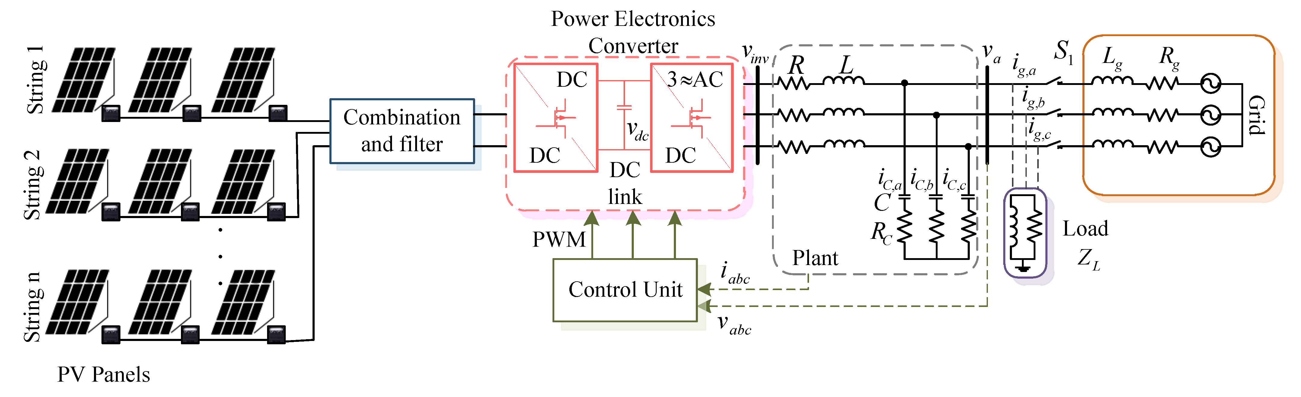
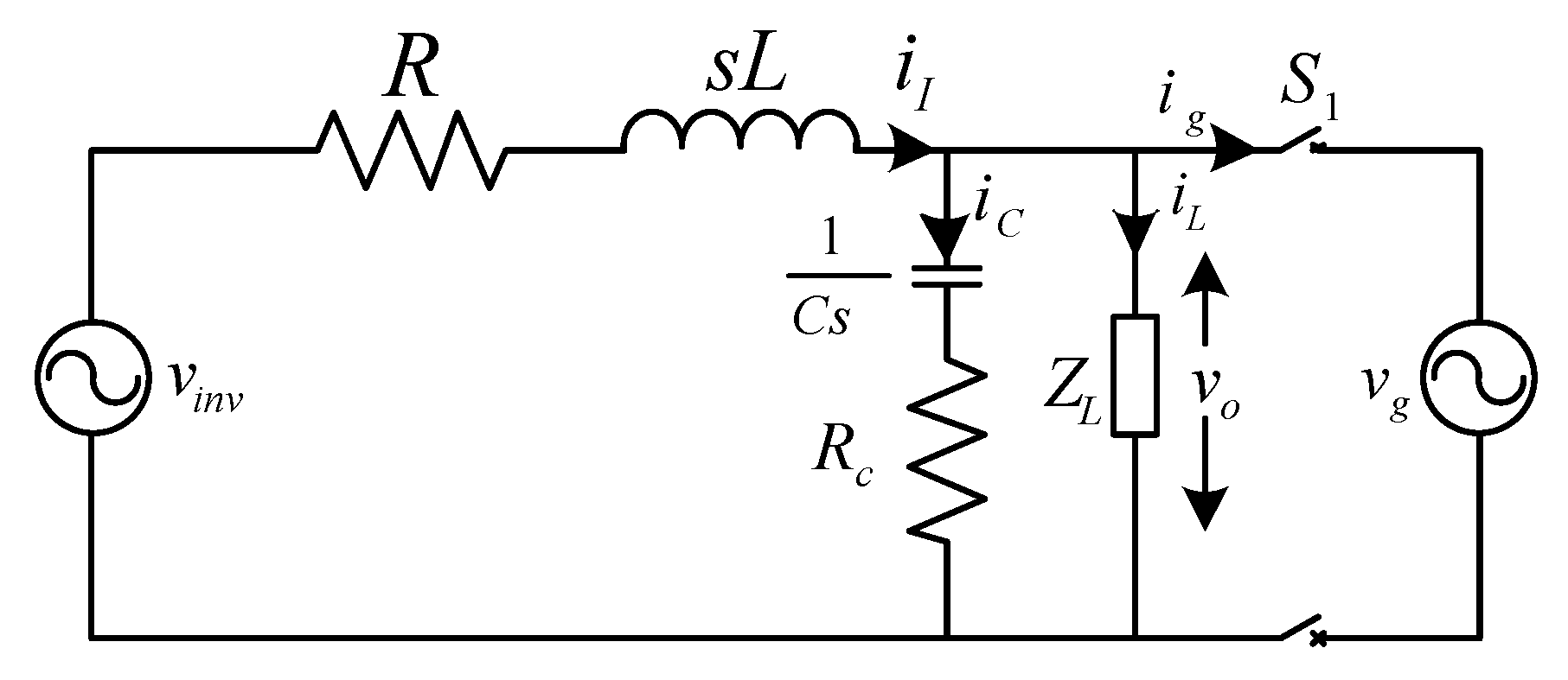
2. System Configuration and Model Derivation

The general overview of a three-phase grid-connected distributed generation (DG) unit with a resistive-inductive (RL) load is shown in Figure 1. This configuration has a primary energy source with a DC-DC boost converter and a three-phase voltage source inverter (3- ϕ VSI) connected at the point of common coupling (PCC) through an LC filter and RL load. The switch S 1 at the grid side of the system is used to achieve the grid-connected and standalone operation of the DG unit. An ideal three-phase voltage source is considered as the main grid with R g and L g components per phase. The major challenge with this configuration is to maintain voltage and frequency at the PCC and coordinate the operation of reclosures and protective relays for safe and quick disconnection of DGs from the utility during the grid-side abnormalities with compliance to the grid standards [25,26]. This operation also involves automatic reconnecting, or intervention of the operator to reclose the DG connection with the grid after the abnormality is cleared. All these operations require the system to be equipped with an accurate islanding detection mechanism [27,28,29] and a robust and smooth seamless transition control infrastructure.
To identify the state-space representation of the configuration in Figure 1 for standalone and grid-connected modes, a simplified network is developed, as shown in Figure 2. The equations governing these modes of operation are derived as
v i n v , a b c = R i I , a b c + L d i I , a b c d t + v 0 , a b c i I , a b c = C d v 0 , a b c d t + i L , a b c + i g , a b c
where v i n v , a b c is the vector representation of the output voltage at each phase of the inverter, i I , a b c is the vector representation of the output current at each phase of the inverter, L is the filter inductance, v 0 , a b c is the voltage at the PCC, C is the filter capacitance, i L , a b c is the current flowing through the three-phase RL Load, and i g , a b c is the three-phase grid current.
Furthermore, the state-space representation in (1) is simplified for the grid-tied mode by formulating the stationary reference frame, α β , as a fact that grid impedance is less than the base impedance. Here, v 0 is equal to v g , and without the loss of generality, the modified formulation is given as
v i n v α = R i I α + L d i I α d t + v g α v i n v β = R i I β + L d i I β d t + v g β .
Therefore, by considering the Laplace domain for nominal values of the filter components, the ideal model of the system is given as
G ˜ P i , α β = i I , α β v i n v , α β v g , α β = 1 s L 0 + R 0
where G ˜ P i is the model representation that can be controlled with a current control loop. The above equation provides an aspect of implementing model-based control with the grid-connected mode of the configuration in Figure 1.
Furthermore, for an islanded or standalone mode of operation, the v 0 is equal to the load voltage, and its stationary frame representation is given as
v i n v α = R i I α + L d i I α d t + v C α v i n v β = R i I β + L d i I β d t + v C β .
For an islanded operation, the main objective is to maintain the load voltage. Hence, the system model based on the inverter output voltage and the voltage across the filter capacitor is derived as
G ˜ P v = v C , α β v i n v , α β = 1 s 2 C 0 L 0 + s R 0 C 0 + 1
where G ˜ P v identifies the model representation of the plant that can be controlled with the voltage control loop. The details of the control methodology associated with the VSI, and the development of the intelligent transition system are discussed in the further sections.

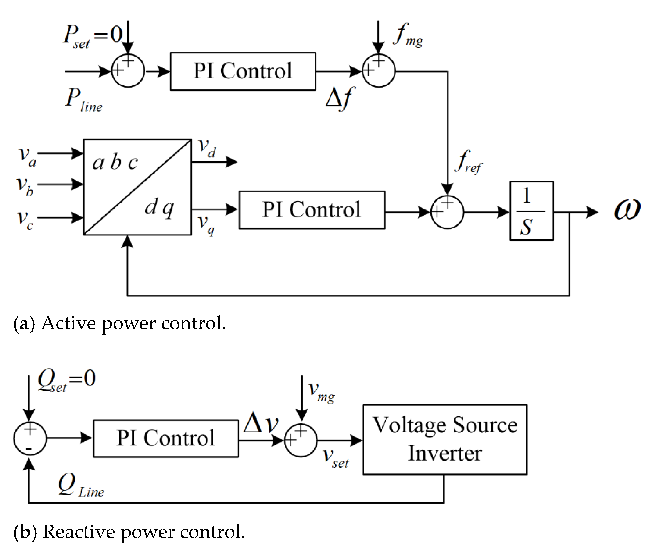
3. Control Development for Voltage Source Inverter

As per the details provided in Section 2, the control model of a three-phase inverter is developed. The inverter needs to be capable enough to adject the output frequency and voltage based on the changes observed from the setpoint in the droop controller. The value of current and the voltage for each phase is measured locally and then transformed in the d q frame of reference, as represented in Figure 3. The transformation facilitates an effortless implementation of the control mechanism.

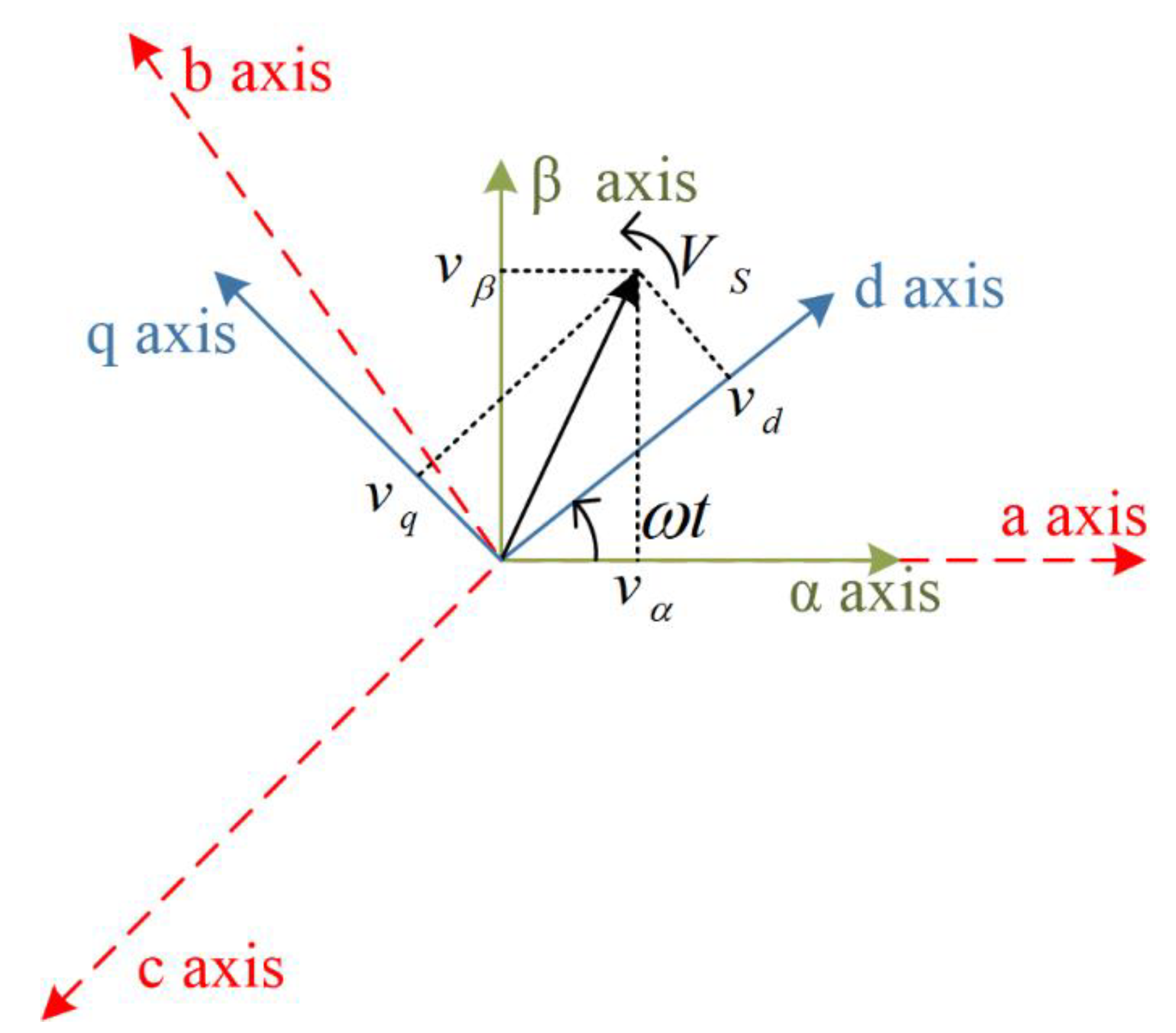
3.1. Reference Frame

The d q transformation operates in two stages: initially, the a b c parameters are converted into an α β frame, which is further transformed into a d q rotating frame of reference [30]. The transformation aids the system control by converting the rotation frame components into a stationary frame. This reduces the complexity of the controller, and the implementation of a decoupled linear controller can be enabled.
As per Figure 3, the rotating angle between the d q frame with respect to the α β frame is represented by a rotating angle, which is denoted by θ . The value of the q axis is fixed to zero for locking the stationary frame with the rotating frame.
The mathematical representation of the a b c α β transformation can be expressed as:
[ x α x β ] = 2 3 [ 1 1 / 2 1 / 2 0 3 / 2 3 / 2   ] [ x a x b x c ] .
Furthermore, the α β d q transformation is expressed as:
[ x d x q ] = [ s i n ω t c o s ω t c o s ω t s i n ω t ] [ x α x β ]
where x is a representation of the value to be transformed.

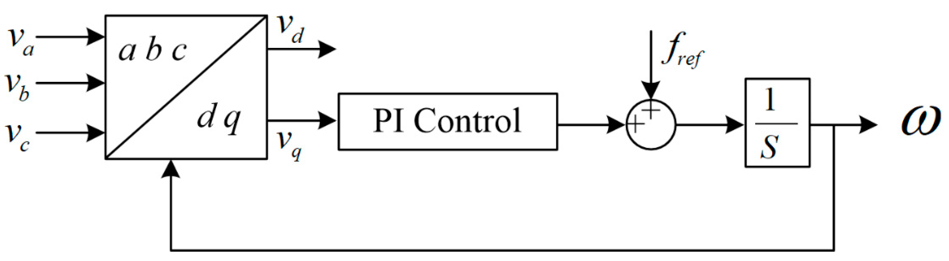
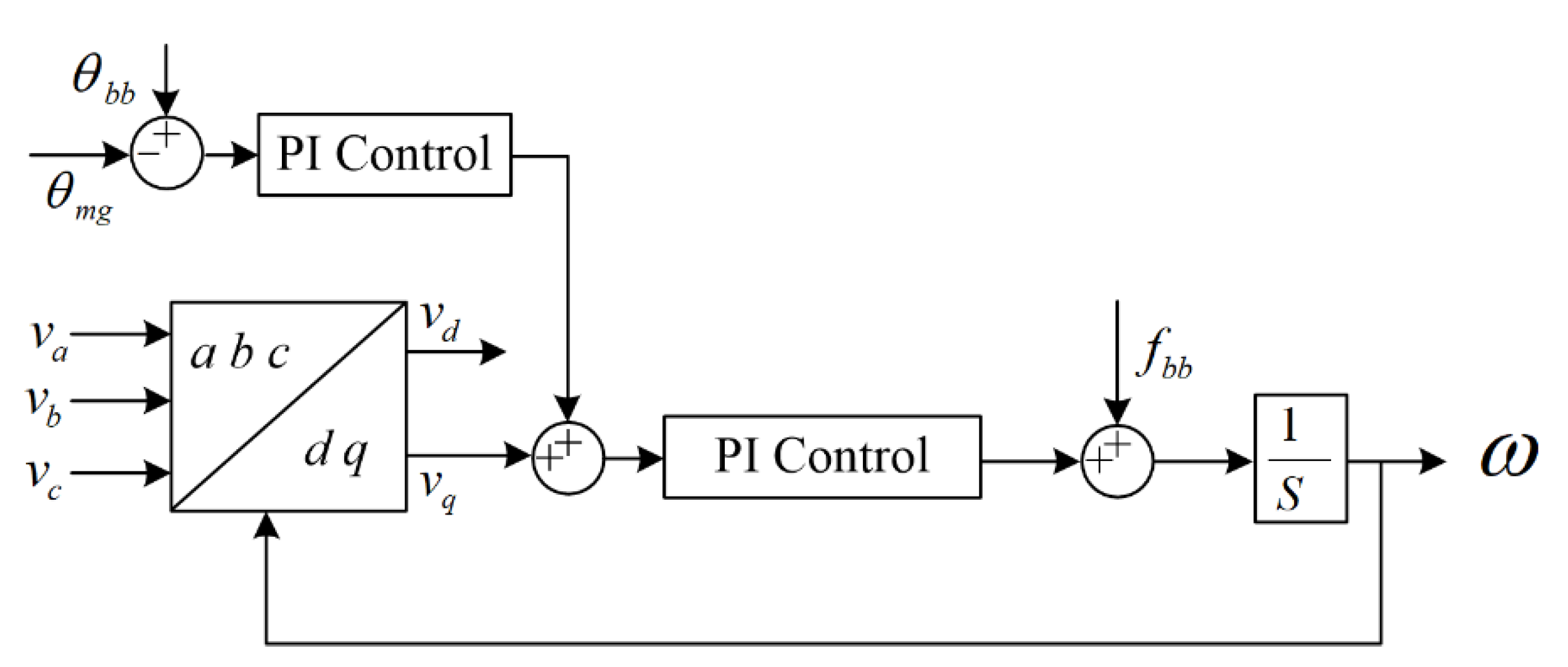
3.2. Phase-Locked Loop

The phase-locked loop (PLL) is configured based on the d q transformation [31]. The phase angle and the frequency of the inverter are measured using PLL. A conventional PLL consists of a reference signal, phase detector, and filter unit. Whereas in synchronous reference frame phase-locked loop (SRF-PLL), the components are similar with the insertion of a d q transformation block by keeping the q-axis value zero, the phase is locked with the rotating frame of reference, as represented in Figure 4 [31,32]. The signal is fed to the PI controller and further added with the frequency frame of reference. By integrating frequency over the time step, value of the phase angle can be achieved, which is fed back to the d q transformation block to close the loop. If the q-axis is driven at zero, then the desired frequency is achieved, whereas the other parameters obtained can be used for further control.

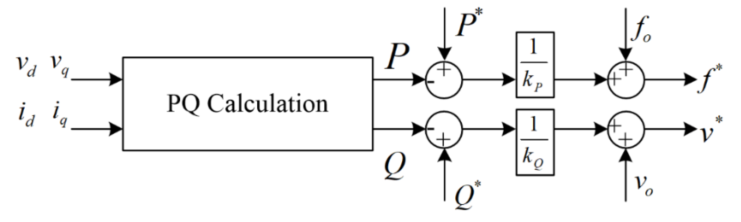
3.3. Droop Implementation

The droop controller is implemented to identify the change in the measure and reference value, as represented in Figure 5 [33]. The active (P) and reactive (Q) power are calculated from the v d ,   v q and i d ,   i q , which are measured locally and transformed. The expression for P and Q calculations are as follows:
P = v d i d + v q i q
Q = v q i d v d i q .

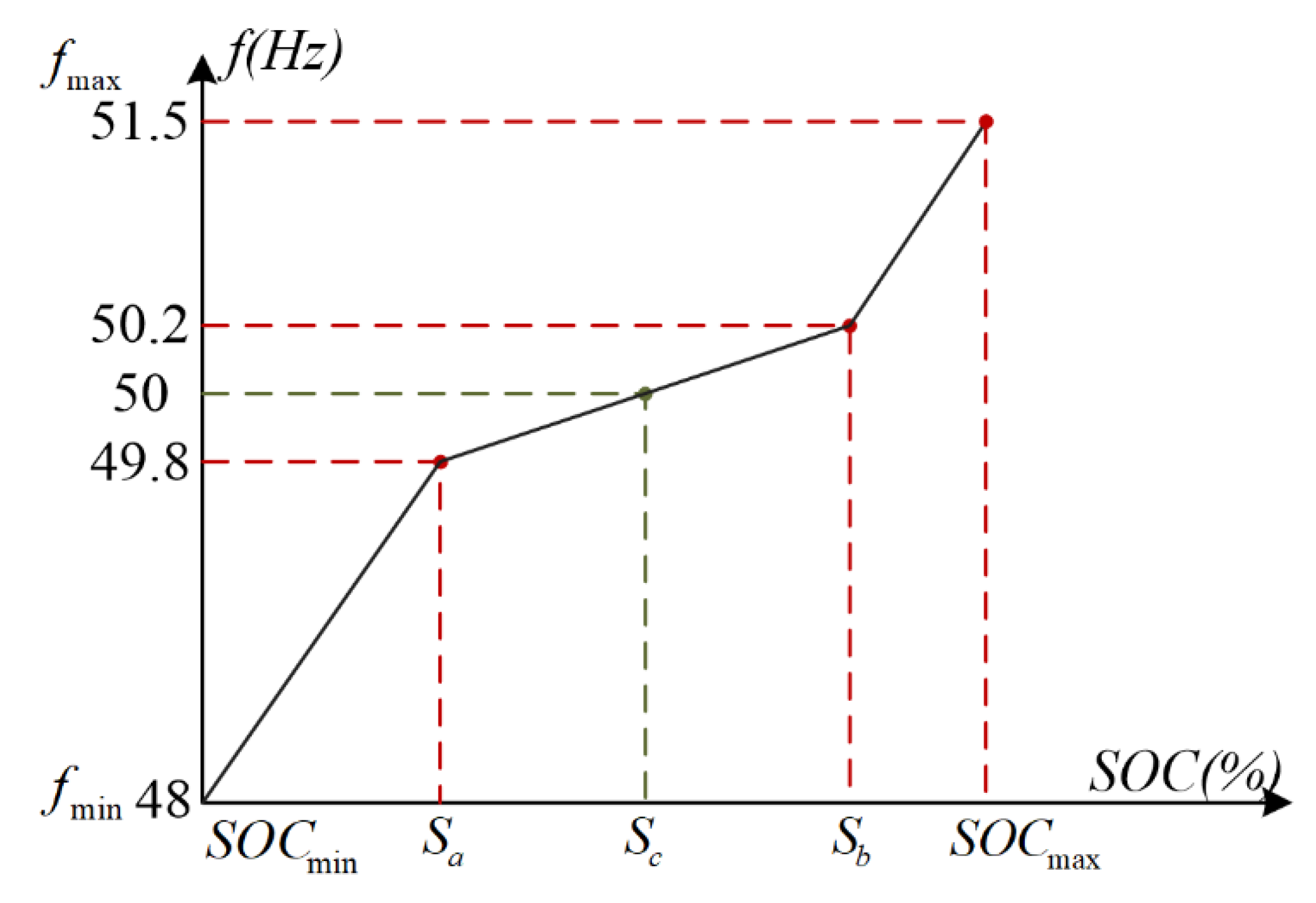
3.3.1. Frequency Setpoint

The P and Q values are fed to the droop controller to obtain the operating voltage and frequency. The conventional grid used to have the operating frequency fixed at the nominal value [34,35,36]. However, with the improvement in the grid, the nature of the frequency has become dynamic. The frequency setpoint is chosen based on the battery state of charge (SOC). The frequency ( f s o c ) dependency on SOC is represented by the equation:
f s o c = { 0.018 . S O C + 0.96                                                 ( f S O C < 0.2 ) 0.008 60 . S O C + 1.004 0.00880 60                                   ( 0.2 < f S O C < 0.6 ) 0.018 . S O C + 0.86                                                 ( f S O C > 0.6 )
Furthermore, Figure 6 represents the SOC dependency. The slopes determine the battery SOC. The steep slope represents that the condition is critical, and the battery is charging and discharging at a faster rate.
For making the controller more robust, a control loop with f o is formulated. The frequency of change in active power is also considered for determining f o . The active power change counters the frequency change during power exchange. Hence, the frequency change is damped to protect the system from power imbalance. The expression can be denoted as:
f 0 = f S O C + f d P
where f d p is the frequency change during the power exchange.

3.3.2. Voltage Controller

After the SRF-PLL and obtaining the frequency setpoint, the voltage control with power sharing needs to be considered. A feedforward control is considered with current, and the voltage of each phase is transformed to the d q frame. The current reference i d * and i q * are formulated by feeding the PI controller with v d and v q . The reference can be mathematically represented as:
i d * = i 0 d * + c f d v d d t ω C f v q
i q * = i 0 q * + c f d v q d t ω C f v d
v d * = v d k p ( i d * i d ) k i i d * i d s + ω L f i q
v q * = v q k p ( i q * i q ) k i i q * i q s + ω L f i d
where c f and L f represent the capacitance and inductance of the filter, respectively. The voltage references are denoted by v d * and v q * . The signals are again transformed from d q to a b c per phase of the inverter. The frequency setpoint is incorporated to attain the desired frequency and voltage for the inverter.

3.3.3. Virtual Impedance

To overcome the resistive nature of low voltage, a virtual impedance is added into the system. Adding up physical inductance to the power system is a bulky and expensive solution; hence, to avoid that and attain a desired inductive behavior, a decoupled current is multiplied with the required inductance value [37,38]. The voltage references after adding the virtual impedance are expressed as follows:
v d , v * = v d * ω L v i q
v q , v * = v q * ω L v i d
where the virtual reactance is denoted by L v .

3.3.4. Voltage Compensation

The voltage compensation reduces the losses that a power system may suffer due to the existing line connection. The voltage compensator is designed similar to the virtual impedance where the amount of voltage drop is added to the voltage setpoint. The expression for the voltage drop is as:
v d = i d . R l
v q = i q . R l
where the line resistance is represented by R l . The derivative value is added to the setpoint, and the d q reference value can be mathematically represented as:
v r e f , d = v d k p ( i d * i d ) k i ( i d * i d ) s + ω L f i q + ω L v i q + i d . R
v r e f , d = v q k p ( i q * i q ) k i ( i q * i q ) s + ω L f i d + ω L v i d + i q . R .

4. Seamless Transition Control

The need for a robust and smooth seamless transition control infrastructure has been emphasized in the previous sections. In this section, the development of this seamless controller will be achieved with two main processes, which can be listed as the synchronization process and an islanding process. The synchronization process of the seamless controller implements relevant loops of voltage and phase synchronization to reconnect the islanded DG with the grid. Furthermore, the islanded process has two aspects: an intentional islanding and an unintentional islanding. During the intentional islanding, the controller has sufficient information of the planned disconnection and minimizes the transients during the process. In contrast, during an unintentional islanding condition, the process is abrupt with unforeseen events. Here, the controller must impose fast actions to minimize the damages in the system.

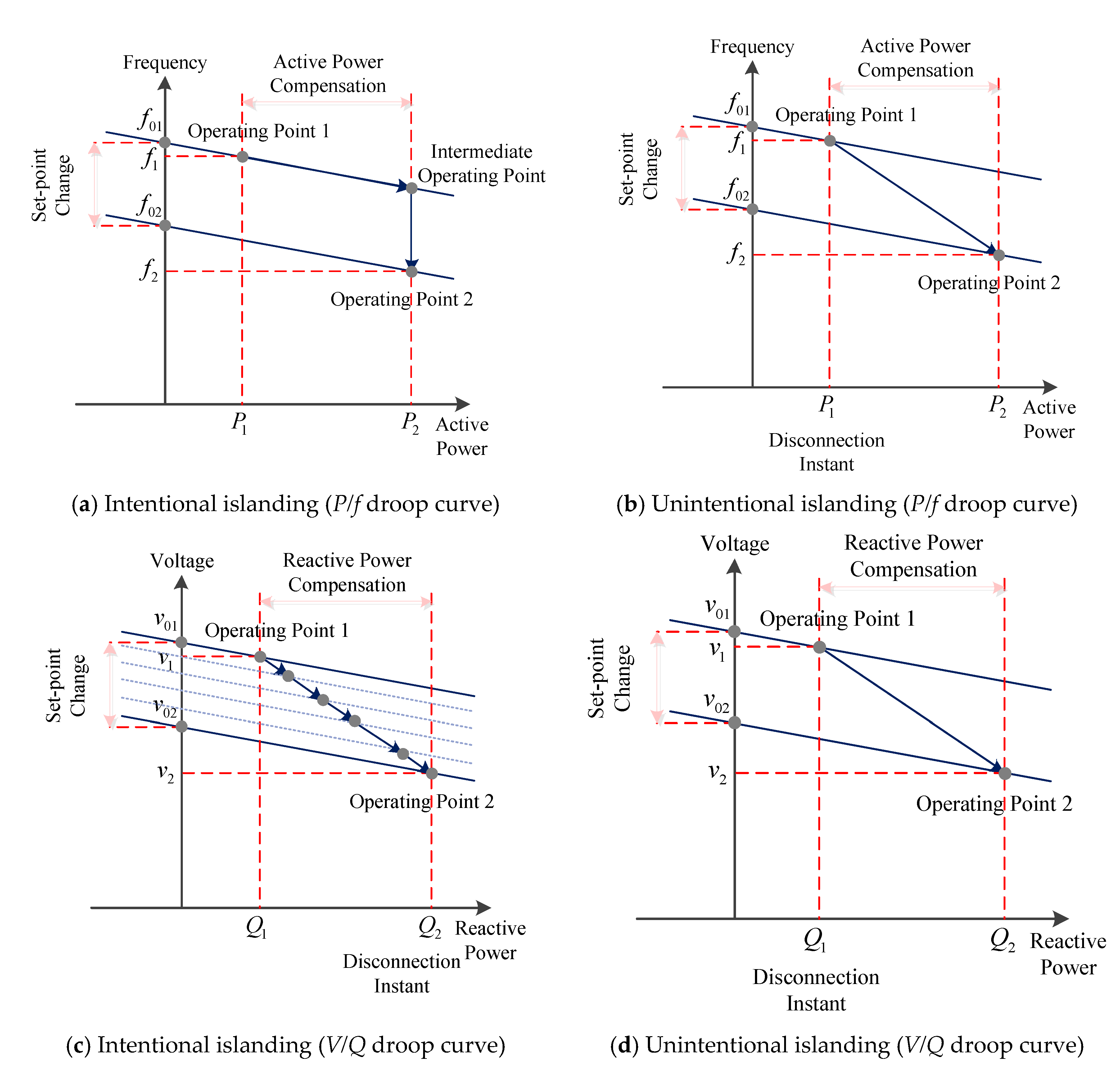
4.1. Transition from Grid-Connected to Standalone Mode

The main challenge of this transition process is to maintain the voltage and frequency levels within the predefined limits of grid standards [39,40]. Generally, for an islanded system, the inverter power output moves along the droop curve, and the setpoint of frequency f 0 depends on the SOC of the Energy Storage System (ESS) in the system. Hence, as the DG is disconnected from the grid, the frequency shifts immediately to the setpoint, especially during a significant amount of incoming power, which results in large disturbances. However, when the system is reconnected in the grid, it either feeds power into the system or receives the power from the grid to satisfy the loads. Here, the frequency either decreases or increases depending on the power exchange, and when the equilibrium between both the points is reached, the system achieves steady state.

4.1.1. Intentional Islanding

This section develops the controller to prepare the DG for a disconnection during an intentional islanding case. The disconnection process is explained based on the P / F and V / Q droop curve characteristics, as shown in Figure 7a–d, respectively.
In Figure 7, the intentional and unintentional islanding conditions based on P / f droop curve characteristics are shown to identify the the change in operating points, especially the frequency setpoints f 01 and f 02 of the DG system before and after the disconnection process. Here, f 01 is the interconnected system setpoint, and f 02 is the original frequency setpoint of the system. Initially, before the disconnection process, the DG interconnection receives active power as per the load requirement, but after the disconnection process, the power flow in the system changes, which results in a sudden decrease of the frequency. Here, the frequency setpoint is estimated through the derivative of the active power and through the SOC of the ESS. Generally, the setpoint estimated through the SOC is developed for longer periods of disconnection and cannot be changed. However, during intentional islanding, the derivative of active power can be planned through the frequency change while the DG is operating in the grid-connected mode. This reduces the frequency change, and the droop curve alters, as shown in Figure 7.
Similarly, the V / Q droop curve characteristics during the intentional and unintentional islanding conditions are shown in Figure 7 to identify the change in the voltage setpoints v 01 and v 02 of the DG system before and after the disconnection process. Here, v 01 is the interconnected system voltage setpoint, and v 02 is the original voltage setpoint of the DG system. As the DG is islanded, the system holds an inherent voltage setpoint depending upon the state of the system, and it jumps back to the original setpoint due to the influence of line voltage compensations and virtual impedance. This phenomenon is expected to create a significant disturbance based on the reactive power required to restore the voltage during the fault ride-through process. This can be further minimized by relatively controlling the reactive power sharing in the system prior to the DG disconnection [41,42]. To achieve this, the voltage and frequency deviation with the droop control needs to be implemented for creating a power flow between the connected DGs. This indicates that an additional deviation is provided to the voltage and frequency setpoints to manipulate the line active and reactive power regardless of the other parameters in the system. The control loops shown in Figure 8 set the line active and reactive power to zero for the intentional islanding condition. In both these cases, the line power is fed to a PI controller, which provides the voltage and frequency deviations until the line power is set to zero.

4.1.2. Unintentional Islanding

This section develops the controller to prepare the DG for a disconnection during an unintentional islanding case. This process is implemented with a fuzzy inference system (FIS), which overcomes the drawback of fixed droop gain with the conventional control in the systems dynamic performance. The FIS achieves the flexibility in the droop gain by incorporating both the magnitude and derivative of the active power exchange P in the system [43,44]. The inverse relation of these parameters with the droop gain is expressed as
f = k p P
V = k q P .
From (22), it is identified that the frequency deviation f is proportional to the product of exchanged active power P and the droop gain k p . Similarly, the voltage deviation V is proportional to the product of exchanged reactive power and the droop gain k q . These equations indicate that under a constant droop gain, the system is more unstable for large active and reactive power deviation. Hence, an effective pairing of the droop gain with the fuzzy controller will stabilize the deviation and its derivative. The details of the fuzzy controller for seamless disconnection from the grid are discussed in the further sections.
Fuzzy Droop Controller: The details of the FIS and their application to power system and power electronic applications are widely discussed in the literature [45,46,47,48,49]. The basic block representation of the FIS process in the development of the droop controller is shown in Figure 9.
The process of developing a seamless control action with the fuzzy droop controller is achieved in three steps: fuzzy sets, rule development, and defuzzification. In the first step, the fuzzy sets are created to map the membership functions in a range of 0 to 1 between both the inputs and the output variables. In this condition, the active power exchange and its derivative are input variables for the development of the fuzzy controller. Here, a small low-pass filter is used with the derivative input of the active power exchange. This is to filter the distorted values under the derivative function of the unstable active power measurements. Furthermore, the droop gains are obtained as the outputs of the controller. The mapping between the inputs and outputs with the membership functions i.e., the fuzzy sets, are shown in Figure 10.
The fuzzy set of active power input shown in Figure 10a is developed with five membership functions, and the range of each membership function represents the power exchanged. Each membership function in the fuzzy set is termed as big negative ( B N ) , low negative ( L N ) , zero ( Z ) , low positive ( L P ) , and big positive ( B P ) . Furthermore, it can be identified that the membership functions overlap with each other; this signifies that the variable does not have a single truth value but lays over multiple regions. Sometimes, this value can either be L N , B N , or both. In this case, the degree of correspondence to the value of the function plays a major role. To estimate the degree of correspondence, a value of interest is inserted to the horizontal axis of the function, and the derivation of a projected value is approximated at the upper boundary of the matching function. Similarly, for the derivative of the active power, the fuzzy set created with five membership functions is shown in Figure 10b. The membership functions are termed as a big negative change ( B N C ) , low negative change ( L N C ) , zero change ( Z C ) , low positive change ( L P C ) , and big positive change ( B P C ) . Furthermore, the fuzzy set for droop change is developed with four membership functions as shown in Figure 10c, and each of those are termed as zero (Z), low change (LC), medium change (MC), and big change (BC).
In the second step of developing the seamless controller, the fuzzy rules are established to determine the control action for each input sample. These rules are framed in such a way that the fuzzy output enhances the dynamic response of the system during sudden power changes while maintaining the system stability. The generalized rule set for fuzzy droop control with reference to the membership functions of active power and derivative of active power are tabulated in Table 1. For a condition where both P and d P are zero, the droop gain is set high to induce the power change. As the DG operation reaches equilibrium, and d P starts to decrease, the droop gain is reduced to maintain the system stability. Furthermore, the output membership rule is selected from the table based on its matching between the P and d P values. Here, the degree of function is inserted into the vertical axis with contrast to the input function, and the corresponding output is obtained from the horizontal axis.
In the final step, the defuzzification process is applied to represent the derived output fuzzy values to crisp values. Generally, there is a wide literature for defuzzification of the fuzzy outputs. In this case, the most used center of area method is implemented. This method combines the results in all the inference steps into a centroid of area. The details of the process are as follows: Initially, the centroid of the corresponding function range is multiplied with the degree of output membership function, and the values are added up. This interprets that the membership functions are integrated over a given range and divided by the summed degree of function. The resultant of this process is a fuzzy droop gain k p , f u z z y and k q , f u z z y such that the voltage and frequency setpoints are set to the VSI. Here, both k p ,   f u z z y and k q , f u z z y are considered to have the same value, as reactive power control is not the major area of focus in this research. Considering the newly obtained droop gains, the droop equation is given as
V V 0 = k q , f u z z y ( P ,   d P ) ( Q Q 0 )
f f 0 = k p , f u z z y ( P ,   d P ) ( P P 0 )
where k q , f u z z y ( P ,   d P ) and k p , f u z z y ( P ,   d P ) can be expressed as the derived fuzzy gains of functions of P and d P . The implementation of the developed fuzzy droop controller with the voltage source inverter is shown in Figure 11.

4.2. Transition from Standalone to Grid-Connected Mode

During the standalone operating mode, the DG is operating at its own voltage and frequency setpoints, which are completely grid-connected operation. This resulted in some inevitable differences between the two modes of operations. According to the theory of power flow in a grid-connected system, the frequency difference in the system, i.e., the voltage and phase angle difference, causes the power flow between the systems. For any condition, if these differences are large, there is a sudden change in the power flow between the system, resulting in unwanted transients and deviations in the system. Hence, to ensure a stable connection of the islanded DGs into the grid, the seamless control action is achieved through the synchronization of voltage, frequency, and the phase angle. Further, the standards for safe connection of DGs with the utility is suggested by various grid codes and in the literature [50,51,52]. The research in [53] indicates that the phase angle difference of a DG to the grid should not be more than 60 0 . More strict requirements for the grid interconnection of DGs are mentioned in the IEEE 1547 standards [54,55,56], and these requirements vary depending on the system size. The grid integration standards for low-voltage grids discussed in [57] proclaim that the phase angle difference of a DG to the grid should not be more than 10 0 . Considering these aspects, all the necessary controller components are examined to eliminate any errors during this grid interconnection process. Furthermore, an additional control layer will be developed to monitor the deprivations within the allowable limits.

4.2.1. Voltage Synchronization

The control structure of VSI discussed in Section 3 is modeled by considering voltage and frequency setpoints as the inputs. However, during the standalone operating mode, the DG is operating at its own voltage and frequency setpoints, which are fed to the VSI. This same principle is used for the synchronization process, but the voltage setpoint is swapped with that of the utility [58]. This control aspect does not need any additional control action except for the change in the setpoint for the VSI, and it has instant response. The control structure of the VSI with the newly obtained voltage setpoints from the grid is shown in Figure 12.

4.2.2. Phase and Frequency Synchronization

The phase-locked loop is used to control both the phase angle and frequency during the grid integration of the DGs. To achieve this, a synchronization loop is implemented using the SRF-PLL, within which a reference frequency is provided as an input. Furthermore, driving the q -axis voltage to zero locks the phase angle to the reference frame to achieve the desired frequency. In this process, the DG tries to match its phase angle and frequency level to the values at the grid and thus obtains new frequency and phase setpoints f g and θ g , respectively. Similar to the voltage synchronization, the frequency synchronization can be achieved by shifting the frequency setpoint to the SRF-PLL from f d g to f g , and this process also has an instant response as the VSI drives the V q to zero. Furthermore, to achieve the phase synchronization an extra control layer is required to eliminate the phase angle difference and to prevent the unwanted power flows during grid integration of DGs. The control structure for the frequency and phase synchronization loop is shown in Figure 13.
From Figure 13, it is observed that by sending out the signals for q -axis control, the phase angle locked to the reference frame can be manipulated. Here, instead of driving the q -axis voltage to zero, the V q setpoint is achieved by driving the phase angle difference to a PI controller. This variation will slightly affect the frequency at the initial stage, but as the phase angle difference decreases, the frequency synchronization can be locked at its original setpoint.

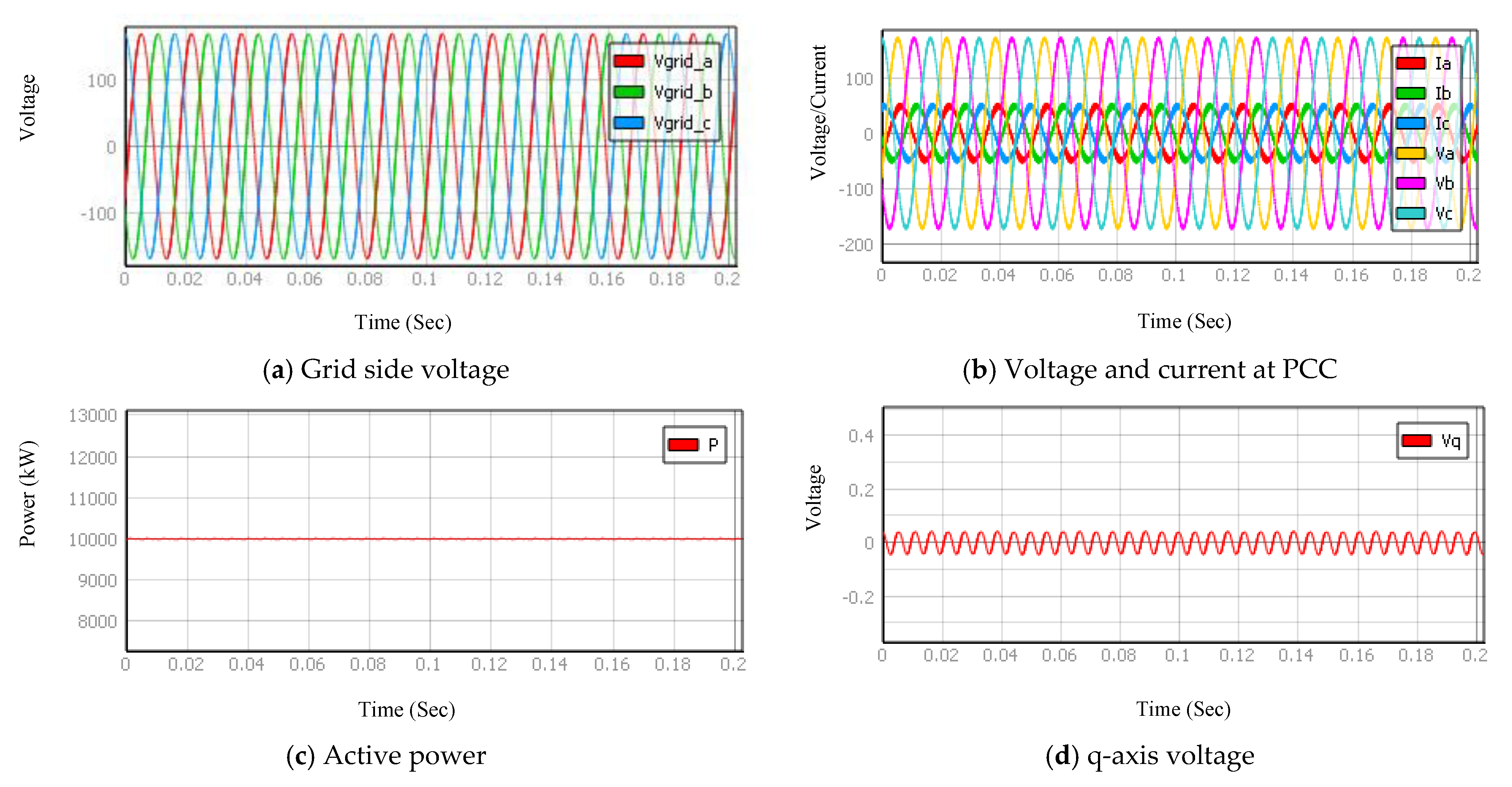
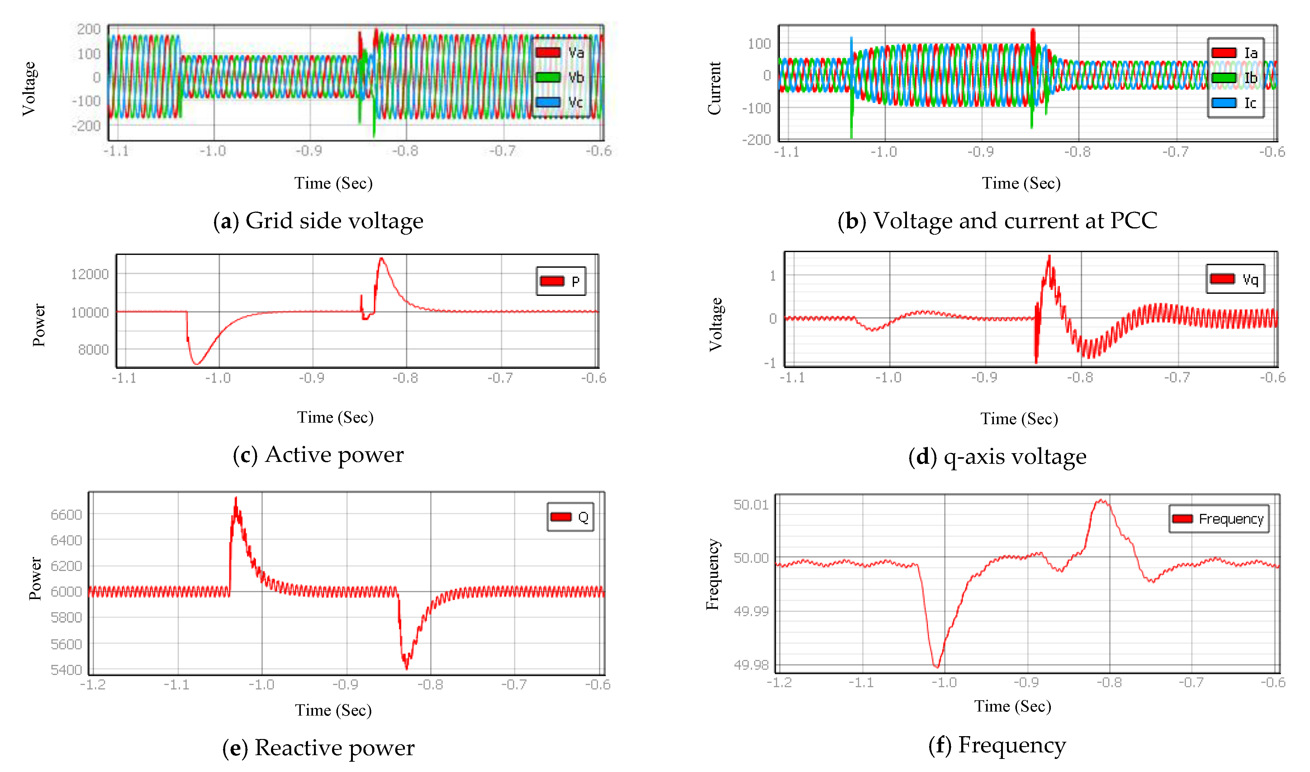
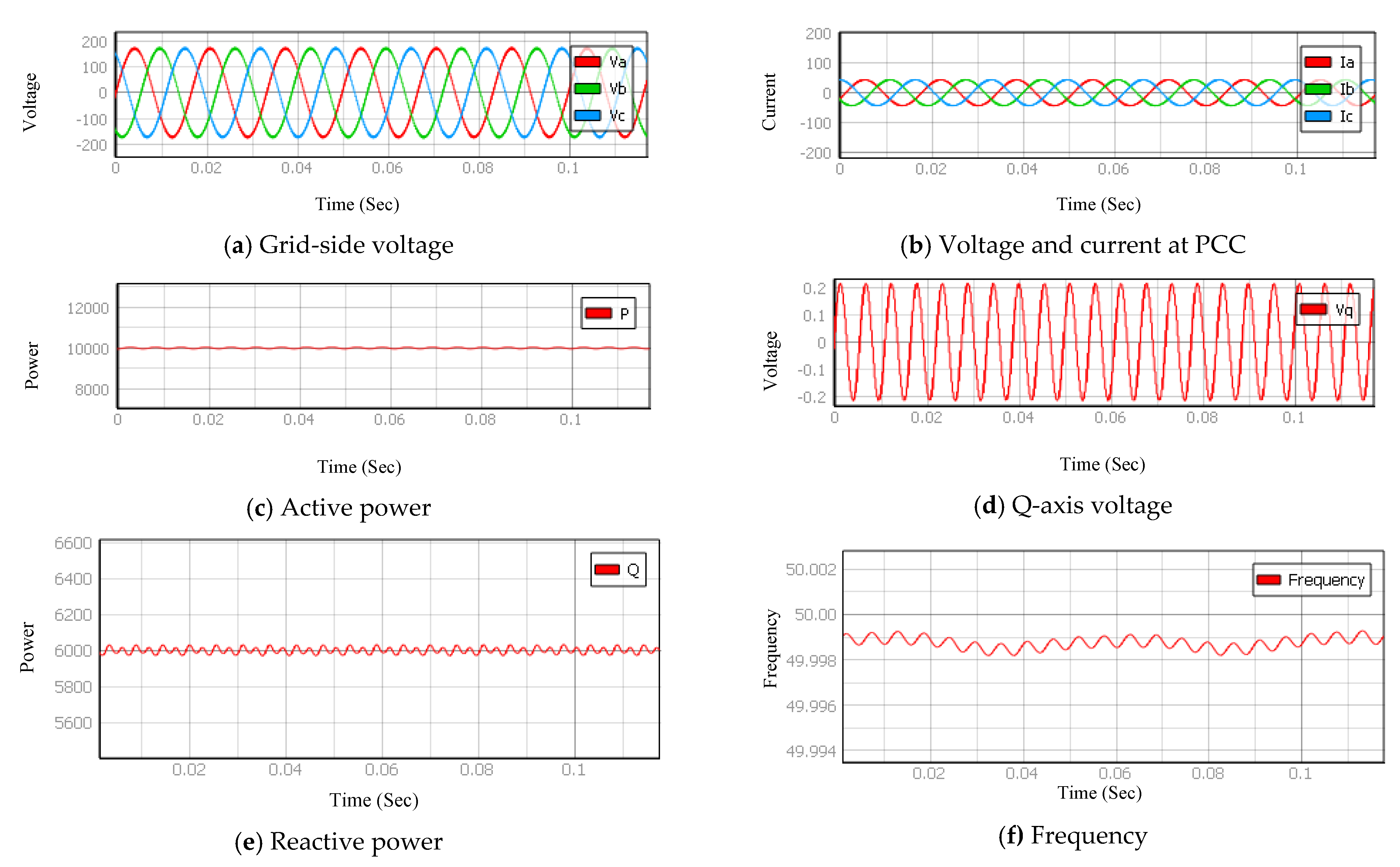
5. Numerical Simulations

For experimental validation of the developed control action, a DG system connected in the grid is developed as shown in Figure 1. The details of the grid-connected DG unit are shown in Table 2. The control action is developed using Typhoon-hardware in loop-application programming interface (HIL-API) with the real-time operation of the DGs in the grid. The DG systems contribute to 10   kWp power output, and the three-phase VSI connected with the DG is operated with the pulse width modulation (PWM) generated from the HIL interface.
The generic user interface (UI) system for establishing interconnection between PV systems and the grid has four machine states, which correspond to the starting up state, running state, disabled state, and islanded state. The generic inputs of the UI are active power curtailment, rate of change of active power, voltage deviation, frequency deviation, and phase angle deviation. As the effect of ESS-SOC on the system operation and control action is found to be negligible, the aspects of SOC are considered constant during the simulation. Furthermore, the battery is considered to be fully charged at 100% SOC. The operating characteristics of the PV systems connected at the point of common coupling are shown in Figure 14. The figure shows the voltage, current, active power, and q -axis voltage for the grid-connected operation of the DG system.
Case 1: Unintentional Islanding Operation
In this case, the fuzzy controller developed for the islanded operation of the DG system is tested. A sample result scenario identifying the low-voltage ride through fault at the grid side and the operation of the developed controller in identifying and disconnecting the DG from the grid is shown in Figure 15.
Initially, the DG is operating in the grid-connected environment. As the grid-side abnormality occurs, the controller identifies the fault in 0.2 s and disconnects the DG from the grid. During the transition period, the fuzzy transition controller lowers the droop gain value to accommodate the sudden change in the active power. As the transition is being achieved, there will be a sudden inrush in voltages and currents. Once the active power deviation decreases, to suppress these transients, the fuzzy tries to increase the droop gain and operate the DG in the standalone mode with its local load. Furthermore, the islanded DG system operates with its RL load within 0.1 s from the time of disconnection. The impact of low-voltage fault in the system can be observed through the voltage, current, active power, and q -axis voltage. Upon the disconnection of the DG and action of the controller, the magnitude of frequency and active power has foreseen a slight variation. The frequency of the DG increased and reached the setpoint according to the state of charge of the battery, and the active power in the connecting line was directed to satisfy the local load. The standalone operating characteristics of the DG unit with an RL load is shown in Figure 16.
Case II: Grid Synchronization Operation
In this case, the DG system is reconnected with the utility after the low-voltage fault is cleared in the system. A sample result of the condition is shown in Figure 17.
From the result, it is identified that upon the reconnections, the fuzzy transition controller tries to identify the voltage, frequency, and phase angle setpoints for synchronizing with the grid operation. Here, from the active power, and the q -axis voltage, it is observed that the synchronization is achieved within 0.1 s of reconnection of DG with the grid. A brief comparison of the characteristics of the developed transition controller with the conventional droop controller during the transition of the DG system from standalone to grid-connected mode is given in Table 3.
Furthermore, a detailed comparison between different characteristics of the developed fuzzy control approach with the conventional droop controller are shown in Table 4.
For both the cases, it is identified that the fuzzy transition controller was successful in identifying the grid abnormalities and disconnecting the DG system for standalone operation. Furthermore, it reduces the impact of transients in the system for variation in the active power. It was observed that the magnitude of the active power and q-axis voltage had a major influence during the disconnection instant. Furthermore, the detection time for the islanding scenario and disconnection from the grid takes less time with the developed controller and has better performance. Similarly, the results of case 2 identify that the synchronizing capability of the developed controller is very smooth with better performance and less synchronization time. The developed controller showed increased performance compared to the conventional control techniques, and it increased the overall dynamic stability of the system. In summary, the major aspects achieved through this paper are as follows:
  • The fuzzy transition controller established the dynamic stability of the droop controller and achieved stable disconnection of a DG from the grid.
  • The synchronization method using SRF-PLL estimates the phase angle during the grid synchronization and has significantly improved the synchronization performance.

6. Conclusions

In this paper, the seamless transition control for grid-connected operation of a three-phase DG unit is achieved by modifying the conventional control and also by introducing intelligent control mechanisms. The developed approach is achieved by initially dividing the transition control into two processes: an islanding process and synchronization process. In the islanding process, control modifications for intentional islanding are developed based on the information that is available in the system due to the planned disconnection for driving the active and reactive power setpoints to zero. Furthermore, the unintentional islanding is controlled with the fuzzy inference system by modifying the droop characteristics based on the information of change in active power, voltage, and frequency during the grid abnormal operating condition. In the grid synchronization approach, the stationary reference frame phase-locked loop is modified by driving the phase angle difference to a PI controller with the q -axis voltage setpoint to zero. The developed modifications in the control schemes are tested by simulating two cases: unintentional islanding and grid synchronization during reconnection in a 10   kWp three-phase grid-connected system. The results in both the cases identify that the islanding detection, standalone control, and synchronizing capability of the developed controller are very smooth with better performance and less time.
Furthermore, the work can be extended to show the effectiveness of the developed system by implementing it with an actual system consisting of multiple distributed generation systems.

Author Contributions

Conceptualization, methodology, software, validation, and formal analysis—V.S.B.K. and M.A.K.; Investigation—V.S.B.K. and M.A.K.; Resources, and data curation—V.S.B.K., M.A.K. and A.H.; writing—original draft preparation, writing—review and editing, and visualization—V.S.B.K. and M.A.K.; supervision—A.H., H.W. and F.B.; project administration—A.H., H.W. and F.B. All authors have read and agreed to the published version of the manuscript.

Funding

This research received no external funding.

Data Availability Statement

Data are not available for this research.

Conflicts of Interest

The authors declare no conflict of interest.

References

  1. Dharani, R.; Balasubramonian, M.; Babu, T.S.; Nastasi, B. Load Shifting and Peak Clipping for Reducing Energy Consumption in an Indian University Campus. Energies 2021, 14, 558. [Google Scholar] [CrossRef]
  2. Amer, A.; Shaban, K.; Gaouda, A.; Massoud, A. Home Energy Management System Embedded with a Multi-Objective Demand Response Optimization Model to Benefit Customers and Operators. Energies 2021, 14, 257. [Google Scholar] [CrossRef]
  3. Rakhshani, E.; Rouzbehi, K.; Sánchez, A.J.; Tobar, A.C.; Pouresmaeil, E. Integration of Large Scale PV-Based Generation into Power Systems: A Survey. Energies 2019, 12, 1425. [Google Scholar] [CrossRef] [Green Version]
  4. Zhang, J.; Huang, L.; Shu, J.; Wang, H.; Ding, J. Energy Management of PV-diesel-battery Hybrid Power System for Island Stand-alone Micro-grid. Energy Procedia 2017, 105, 2201–2206. [Google Scholar] [CrossRef]
  5. Teodorescu, R.; Blaabjerg, F. Flexible Control of Small Wind Turbines with Grid Failure Detection Operating in Stand-Alone and Grid-Connected Mode. IEEE Trans. Power Electron. 2004, 19, 1323–1332. [Google Scholar] [CrossRef]
  6. Khan, M.A.; Kurukuru, V.S.B.; Haque, A.; Mekhilef, S. Islanding Classification Mechanism for Grid-Connected Photovoltaic Systems. IEEE J. Emerg. Sel. Top. Power Electron. 2021, 9, 1966–1975. [Google Scholar] [CrossRef]
  7. Khan, M.A.; Haque, A.; Kurukuru, V.S.B.; Saad, M. Advanced Control Strategy with Voltage Sag Classification for Single-Phase Grid-Connected Photovoltaic System. IEEE J. Emerg. Sel. Top. Ind. Electron. 2020. [Google Scholar] [CrossRef]
  8. Khan, M.A.; Haque, A.; Kurukuru, V.S.B. Dynamic Voltage Support for Low Voltage Ride Through Operation in Single-Phase Grid-Connected Photovoltaic Systems. IEEE Trans. Power Electron. 2021. [Google Scholar] [CrossRef]
  9. Fatama, A.Z.; Khan, M.A.; Kurukuru, V.S.B.; Haque, A.; Blaabjerg, F. Coordinated reactive power strategy using static synchronous compensator for photovoltaic inverters. Int. Trans. Electr. Energy Syst. 2020, 30. [Google Scholar] [CrossRef]
  10. Dong, N.; Thacker, T.; Cvetkovic, I.; Burgos, R.; Boroyevich, D.; Wang, F.; Skutt, G. Modes of Operation and System-Level Control of Single-Phase Bidirectional PWM Converter for Microgrid Systems. IEEE Trans. Smart Grid 2012, 3, 93–104. [Google Scholar] [CrossRef]
  11. Shi, K.; Zhou, G.; Xu, P.; Ye, H.; Tan, F. The Integrated Switching Control Strategy for Grid-Connected and Islanding Operation of Micro-Grid Inverters Based on a Virtual Synchronous Generator. Energies 2018, 11, 1544. [Google Scholar] [CrossRef] [Green Version]
  12. Yi, Z.; Dong, W.; Etemadi, A.H. A Unified Control and Power Management Scheme for PV-Battery-Based Hybrid Microgrids for Both Grid-Connected and Islanded Modes. IEEE Trans. Smart Grid 2018, 9, 5975–5985. [Google Scholar] [CrossRef]
  13. Karimi-Ghartemani, M.; Khajehoddin, S.A.; Piya, P.; Ebrahimi, M. Universal Controller for Three-Phase Inverters in a Microgrid. IEEE J. Emerg. Sel. Top. Power Electron. 2016, 4, 1342–1353. [Google Scholar] [CrossRef]
  14. Khan, M.A.; Haque, A.; Kurukuru, V.S.B.; Wang, H.; Blaabjerg, F. Standalone operation of Distributed Generation Systems with Improved Harmonic Elimination Scheme. IEEE J. Emerg. Sel. Top. Power Electron. 2021, 1. [Google Scholar] [CrossRef]
  15. Khan, M.A.; Haque, A.; Kurukuru, V.B. Performance assessment of stand-alone transformerless inverters. Int. Trans. Electr. Energy Syst. 2020, 30, 1–20. [Google Scholar] [CrossRef]
  16. Khan, M.A.; Haque, A.; Kurukuru, V.S.B. Intelligent control of a novel transformerless inverter topology for photovoltaic applications. Electr. Eng. 2020, 102, 627–641. [Google Scholar] [CrossRef]
  17. Khan, M.A.; Haque, A.; Kurukuru, V.S.B. Voltage-Balancing Control for Stand-Alone H5 Transformerless Inverters. In Lecture Notes in Electrical Engineering; Springer Science and Business Media LLC: Berlin, Germany, 2019; pp. 663–675. [Google Scholar]
  18. Arafat, N.; Palle, S.; Sozer, Y.; Husain, I. Transition Control Strategy Between Standalone and Grid-Connected Operations of Voltage-Source Inverters. IEEE Trans. Ind. Appl. 2012, 48, 1516–1525. [Google Scholar] [CrossRef]
  19. Sreekumar, T.; Jiji, K. Comparison of Proportional-Integral (P-I) and Integral-Proportional (I-P) controllers for speed control in vector controlled induction Motor drive. In Proceedings of the 2012 2nd International Conference on Power, Control and Embedded Systems, Institute of Electrical and Electronics Engineers, Allahabad, India, 17–19 December 2012; pp. 1–6. [Google Scholar]
  20. Lim, K.; Choi, J. PR based indirect current control for seamless transfer of grid-connected inverter. In Proceedings of the 2016 IEEE 8th International Power Electronics and Motion Control Conference (IPEMC-ECCE Asia), Institute of Electrical and Electronics Engineers (IEEE), Hefei, China, 22–26 May 2016; pp. 3749–3755. [Google Scholar]
  21. Zong, X. A Single Phase Grid Connected DC/AC Inverter with Reactive Power Control for Residential PV Application. Master’s Degree, University of Toronto, Toronto, ON, Canada, 2011. [Google Scholar]
  22. Ibrahim-Mohamed, Y.; Radwan, A.A. Hierarchical Control System for Robust Microgrid Operation and Seamless Mode Transfer in Active Distribution Systems. IEEE Trans. Smart Grid 2011, 2, 352–362. [Google Scholar] [CrossRef]
  23. Li, X.; Zhang, H.; Shadmand, M.B.; Balog, R. Model Predictive Control of a Voltage-Source Inverter with Seamless Transition Between Islanded and Grid-Connected Operations. IEEE Trans. Ind. Electron. 2017, 64, 7906–7918. [Google Scholar] [CrossRef]
  24. Taul, M.G.; Wang, X.; Davari, P.; Blaabjerg, F. An Overview of Assessment Methods for Synchronization Stability of Grid-Connected Converters Under Severe Symmetrical Grid Faults. IEEE Trans. Power Electron. 2019, 34, 9655–9670. [Google Scholar] [CrossRef] [Green Version]
  25. Tsimtsios, A.; Voglitsis, D.; Perpinias, I.; Korkas, C.; Papanikolaou, N. On the Conflict between LVRT and Line Protection in LV Distribution Systems with PVs: A Current-Limitation-Based Solution. Energies 2019, 12, 2909. [Google Scholar] [CrossRef] [Green Version]
  26. Vegunta, S.; Higginson, M.; Kenarangui, Y.; Li, G.; Zabel, D.; Tasdighi, M.; Shadman, A. AC Microgrid Protection System Design Challenges—A Practical Experience. Energies 2021, 14, 2016. [Google Scholar] [CrossRef]
  27. Fatama, A.-Z.; Haque, A.; Khan, M.A. A Multi Feature Based Islanding Classification Technique for Distributed Generation Systems. In Proceedings of the 2019 International Conference on Machine Learning, Big Data, Cloud and Parallel Computing (COMITCon), Institute of Electrical and Electronics Engineers (IEEE), Haryana, India, 14–16 February 2019; pp. 160–166. [Google Scholar]
  28. Haque, A.; Alshareef, A.; Khan, A.I.; Alam, M.; Kurukuru, V.S.B.; Irshad, K. Data Description Technique-Based Islanding Classification for Single-Phase Grid-Connected Photovoltaic System. Sensors 2020, 20, 3320. [Google Scholar] [CrossRef]
  29. Khan, M.A.; Haque, A.; Kurukuru, V.B. An Efficient Islanding Classification Technique for Single Phase Grid Connected Photovoltaic System. In Proceedings of the 2019 International Conference on Computer and Information Sciences (ICCIS), Institute of Electrical and Electronics Engineers, Aljouf, Saudi Arabia, 10–11 April 2019; pp. 1–6. [Google Scholar]
  30. Levron, Y.; Belikov, J.; Baimel, D. A Tutorial on Dynamics and Control of Power Systems with Distributed and Renewable Energy Sources Based on the DQ0 Transformation. Appl. Sci. 2018, 8, 1661. [Google Scholar] [CrossRef] [Green Version]
  31. Kulkarni, A.; John, V. Design of synchronous reference frame phase-locked loop with the presence of dc offsets in the input voltage. IET Power Electron. 2015, 8, 2435–2443. [Google Scholar] [CrossRef] [Green Version]
  32. Golestan, S.; Guerrero, J. Conventional Synchronous Reference Frame Phase-Locked Loop is an Adaptive Complex Filter. IEEE Trans. Ind. Electron. 2015, 62, 1679–1682. [Google Scholar] [CrossRef] [Green Version]
  33. Khan, M.A.; Haque, A.; Kurukuru, V.S.B. Droop based Low voltage ride through implementation for grid integrated photovoltaic system. In Proceedings of the 2019 International Conference on Power Electronics, Control and Automation (ICPECA), Institute of Electrical and Electronics Engineers (IEEE), New Delhi, India, 16–17 November 2019; pp. 1–5. [Google Scholar]
  34. Toub, M.; Bijaieh, M.M.; Weaver, W.W.; Iii, R.D.R.; Maaroufi, M.; Aniba, G. Droop Control in DQ Coordinates for Fixed Frequency Inverter-Based AC Microgrids. Electronics 2019, 8, 1168. [Google Scholar] [CrossRef] [Green Version]
  35. Gao, D.W. Coordinated Frequency Regulation of BESS with Renewable Generation in Microgrid. In Energy Storage for Sustainable Microgrid; Elsevier BV: Amsterdam, The Netherlands, 2015; pp. e1–e68. [Google Scholar]
  36. Li, R. Grid-connected power conversion of distributed resources. In Distributed Power Resources; Elsevier BV: Amsterdam, The Netherlands, 2019; pp. 19–50. [Google Scholar]
  37. Lyu, Z.; Wei, Q.; Zhang, Y.; Zhao, J.; Manla, E. Adaptive Virtual Impedance Droop Control Based on Consensus Control of Reactive Current. Energies 2018, 11, 1801. [Google Scholar] [CrossRef] [Green Version]
  38. He, J.; Li, Y.W. Analysis, Design, and Implementation of Virtual Impedance for Power Electronics Interfaced Distributed Generation. IEEE Trans. Ind. Appl. 2011, 47, 2525–2538. [Google Scholar] [CrossRef]
  39. Saleh, M.; Esa, Y.; El Hariri, M.; Mohamed, A. Impact of Information and Communication Technology Limitations on Microgrid Operation. Energies 2019, 12, 2926. [Google Scholar] [CrossRef] [Green Version]
  40. Aleem, S.A.; Hussain, S.M.S.; Ustun, T.S. A Review of Strategies to Increase PV Penetration Level in Smart Grids. Energies 2020, 13, 636. [Google Scholar] [CrossRef] [Green Version]
  41. Tran, T.S.; Nguyen, D.T.; Fujita, G. The Analysis of Technical Trend in Islanding Operation, Harmonic Distortion, Stabilizing Frequency, and Voltage of Islanded Entities. Resources 2019, 8, 14. [Google Scholar] [CrossRef] [Green Version]
  42. Das, D.; Gurrala, G.; Shenoy, U.J. Transition between grid-connected mode and islanded mode in VSI-fed microgrids. Sadhana 2017, 42, 1239–1250. [Google Scholar] [CrossRef]
  43. Bubshait, A.; Simoes, M.G. Design of Fuzzy Logic-Based Dynamic Droop Controller of Wind Turbine System for Primary Frequency Support. In Proceedings of the 2018 IEEE Industry Applications Society Annual Meeting (IAS), Institute of Electrical and Electronics Engineers, Portland, OR, USA, 23–27 September 2018; pp. 1–7. [Google Scholar]
  44. Yadav, M.; Jaiswal, P.; Singh, N. Fuzzy Logic-Based Droop Controller for Parallel Inverter in Autonomous Microgrid Using Vectored Controlled Feed-Forward for Unequal Impedance. J. Inst. Eng. India Ser. B 2021, 1–15. [Google Scholar] [CrossRef]
  45. Srinivasan, D.; Liew, A.; Chang, C. Applications of fuzzy systems in power systems. Electr. Power Syst. Res. 1995, 35, 39–43. [Google Scholar] [CrossRef]
  46. Yadaiah, N.; Babu, C.V.S.R.K.; Bhattacharya, J. Fuzzy logic controllers—An application to power systems. In Proceedings of the 2003 IEEE International Workshop on Soft Computing in Industrial Applications, 2003. SMCia/03., Institute of Electrical and Electronics Engineers (IEEE), Binghamton, NY, USA, 25–25 June 2003; pp. 1–6. [Google Scholar]
  47. Sousa, G.C.D.; Bose, B.K. Fuzzy logic applications to power electronics and drives-an overview. In Proceedings of the Proceedings of IECON ’95 –21st Annual Conference on IEEE Industrial Electronics, Institute of Electrical and Electronics Engineers (IEEE), Toronto, ON, Canada, 13–16 October 2002; Volume 1, pp. 57–62. [Google Scholar]
  48. Rodrigues, E.M.G.; Godina, R.; Pouresmaeil, E. Industrial Applications of Power Electronics. Electron. 2020, 9, 1534. [Google Scholar] [CrossRef]
  49. Islam, R.; Hasan, J.; Shipon, R.R.; Sadi, M.A.H.; Abuhussein, A.; Roy, T.K. Neuro Fuzzy Logic Controlled Parallel Resonance Type Fault Current Limiter to Improve the Fault Ride Through Capability of DFIG Based Wind Farm. IEEE Access 2020, 8, 115314–115334. [Google Scholar] [CrossRef]
  50. Notholt, A. Germany’s new code for generation plants connected to medium-voltage networks and its repercussion on inverter control. Renew. Energy Power Qual. J. 2009, 1, 716–720. [Google Scholar] [CrossRef]
  51. Kumar, P.; Singh, A.K. Grid Codes: Goals and Challenges. Smart Sustain. Plan. Cities Reg. 2014, 17–39. [Google Scholar] [CrossRef]
  52. Craciun, B.-I.; Kerekes, T.; Sera, D.; Teodorescu, R. Overview of recent Grid Codes for PV power integration. In Proceedings of the 2012 13th International Conference on Optimization of Electrical and Electronic Equipment (OPTIM), Institute of Electrical and Electronics Engineers, Brasov, Romania, 24–26 May 2012; pp. 959–965. [Google Scholar]
  53. Eto, J.; Lasseter, R.; Schenkman, B.; Stevens, J.; Klapp, D.; VolkommeRr, H.; Linton, E.; Hurtado, H.; Roy, J. Overview of the CERTS Microgrid laboratory Test Bed. In Proceedings of the 2009 CIGRE/IEEE PES Joint Symposium Integration of Wide-Scale Renewable Resources into the Power Delivery System, Alberta, CA, Canada, 29–31 July 2009; p. 1. [Google Scholar]
  54. IEEE Std 1547-2003. IEEE Standard for Interconnecting Distributed Resources with Electric Power Systems; IEEE: Piscataway, NJ, USA, 2003; ISBN 978-0-7381-3721-6. [Google Scholar]
  55. IEEE Std 1547-2014. IEEE Standard for Interconnecting Distributed Resources with Electric Power Systems; IEEE: Piscataway, NJ, USA, 2014. [Google Scholar]
  56. IEEE Std 1547-2018. IEEE Standard for Interconnection and Interoperability of Distributed Energy Resources with Associated Electric Power Systems Interfaces; IEEE: Piscataway, NJ, USA, 2018. [Google Scholar]
  57. Laaksonen, H. Protection Scheme for Island Operated Medium-Voltage Microgrid. Int. Rev. Electr. Eng. (IREE) 2015, 10, 510. [Google Scholar] [CrossRef]
  58. Wang, X.; Taul, M.G.; Wu, H.; Liao, Y.; Blaabjerg, F.; Harnefors, L. Grid-Synchronization Stability of Converter-Based Resources—An Overview. IEEE Open J. Ind. Appl. 2020, 1, 115–134. [Google Scholar] [CrossRef]
Figure 1. Configuration of three-phase grid-connected distributed generation unit with RL load.
Energies 14 03979 g001
Figure 2. Simplified network of three-phase grid-connected distributed generation unit.
Energies 14 03979 g002
Figure 3. Frame of references.
Energies 14 03979 g003
Figure 4. Layout of synchronous reference frame phase-locked loop.
Energies 14 03979 g004
Figure 5. Layout of droop implementation.
Energies 14 03979 g005
Figure 6. Frequency to SOC relationship.
Energies 14 03979 g006
Figure 7. Droop curves during the disconnection instant.
Energies 14 03979 g007
Figure 8. Control loop to set active and reactive power during intentional islanding.
Energies 14 03979 g008
Figure 9. Basic block representation of the fuzzy inference process.
Energies 14 03979 g009
Figure 10. Fuzzy sets for active power input, its derivative, and for droop gain.
Energies 14 03979 g010
Figure 11. Fuzzy droop controller for operation of voltage source inverter.
Energies 14 03979 g011
Figure 12. Control structure of the voltage source inverter with the newly obtained voltage setpoints.
Energies 14 03979 g012
Figure 13. Control structure for the frequency and phase synchronization loop.
Energies 14 03979 g013
Figure 14. Characteristics of the grid-connected DG system.
Energies 14 03979 g014
Figure 15. Characteristics of the DG system during islanding operation.
Energies 14 03979 g015
Figure 16. Characteristics of the islanded DG system.
Energies 14 03979 g016
Figure 17. Characteristics of the DG system during grid synchronization from islanding mode.
Energies 14 03979 g017
Table 1. Established fuzzy rules for frequency droop gain control.
P   ( )   B N L N Z L P B P
d P   ( )
B N C Z L C L C L C Z
L N C L C M C B C L C L C
Z Z M C B C M C Z
L P C L C L C B C M C L C
B P C Z L C L C L C Z
Table 2. Parameters of the three-phase grid-connected inverter.
System ParameterSpecification
DG Power Output 10   kWp
DC Link Capacitor 2000   μ f
DC Link Voltage 650   V
Inverter Rating 10   kW / 12.5   kVA
Inverter Switching Frequency 10   kHz
Filter Resistance 0.1   Ω
Filter Inductance 3   mH
Filter Capacitance 20   μ f
Damping Resistance 15   e 3   Ω
Grid-Side Inductance 5   μ H
Grid-Side Resistance 10   e 3   Ω
Total Battery Capacity 48   V ,   600   AH
Table 3. Comparison between droop and fuzzy characteristics for grid synchronization conditions.
ControllerInitial Phase Angle DifferenceSynchronization Time
Droop Controller2.95 rad3 s
Fuzzy Transition Controller2.9 rad0.6 s
Table 4. Comparison between droop and fuzzy characteristics for all the simulation scenarios.
ConditionDroop Controller
(Conventional Approach)
Fuzzy Transition Controller
(Developed Approach)
Droop Gain [Hz/W]Response Time [s]Oscillation Level [%]FuzzyResponse Time [s]Oscillation Level [%]
Normal Operation0.10.180.19Fuzzy Rules0.0760.07
Unintentional Islanding 0.070.470.49Fuzzy Rules0.1150.17
Grid Synchronization 0.050.430.35Fuzzy Rules0.0920.14
Publisher’s Note: MDPI stays neutral with regard to jurisdictional claims in published maps and institutional affiliations.

