1. Introduction
Limitation of uncontrolled natural gas flows from the ring and/or annular space of a borehole is one of the crucial aspects during sealing of casing in boreholes drilled in formation with a higher risk of gas migration (the so-called exhalation). It relates to the main objective of casing sealing, i.e., ensuring durability and tightness between the lowered casing, on the one hand, and the drillhole wall and the previously cemented casing string, on the other [
1,
2,
3,
4,
5]. As there are cases of gas invasion into the structure of the bonding slurry, resulting in leaks in the structure of the cement coating, it is necessary to carry out research and development work aimed at continually improving the quality of cement slurries formulations and the slurry injection technology [
2,
5,
6,
7]. During cement slurry bonding, in the process of its hydration, gel structure is created and at that time a clear decline of hydrostatic pressure in the ring space of a drillhole is observed. When slurry changes its structure, it is very likely that gas moves in the gelled slurry structure, which may consequently result in gas migration both through fresh and hardened cement slurry [
2,
3,
5,
8,
9,
10,
11,
12,
13].
2. Uncontrolled Flows of Fluids in a Borehole
Interhorizontal flows of drilling fluids (natural gas, crude oil, brine, drilling fluid) are caused by the lack of balance between formation and hydrostatic pressures in the ring space of a wellbore.
Uncontrolled natural gas flows within particular horizons being drilled are called migrations (drillhole no. 1,
Figure 1), whereas gas flow from rock formation on the ground surface is called exhalation (drillhole no. 2,
Figure 1).
The first issues of this kind were observed in the 1960s when making a borehole for gas storage. The topic of uncontrolled natural gas outflows from ring and/or annular spaces of a wellbore is very important in the context of the influence on safety, environmental protection, in terms of legal regulations, with regard to suitable management and exploitation of the borehole area. The results of studies conducted by oil companies (Schlumberger, Halliburton) prove that ca. 15% of failed cementing of a casing string in wellbores are caused by gas migration [
4,
14].
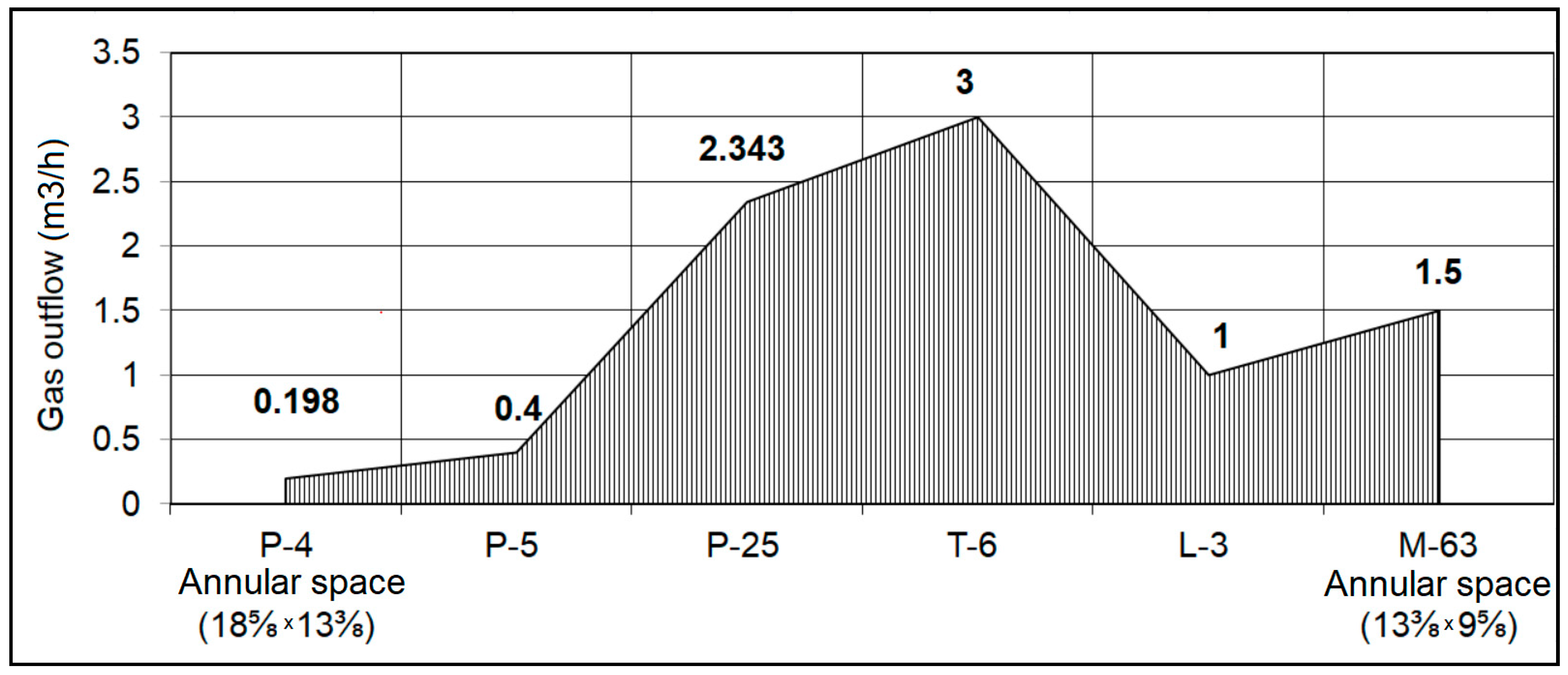
Presently, this problem occurs to a much higher extent, mainly on some gas formations and in boreholes prepared for gas storage. The above is confirmed by the analysis of the state of cementation of boreholes carried out (in the years 2008 to 2011) in the area of the Carpathian Foredeep and in the Carpathians, which is presented in
Figure 2 [
15].
In extreme situations, where an abnormally high pressure occurs after cementing of the casing on a wellhead, it may be necessary to decommission the borehole. In most cases, however, this problem is solved by using different techniques to cement the leaking zone in order to eliminate the gas flow or to reduce the pressure to a value that allows further work to be carried out in compliance with the applicable standards. Such procedures, however, are very costly, so the optimum solution is to minimise uncontrolled gas flows from the design stage of the formulation and the technological parameters of the slurry, while conducting laboratory tests [
3,
16,
17,
18,
19,
20].
3. Minimizing of Uncontrolled Gas Flows
The sealing slurry changes its physical state during hydration from the liquid phase during injection, through the transition phase—gel (slurry bonding), to the solid phase (bonded) slurry. Taking the technological properties of the sealing slurry as a criterion, it can be noted that the potential factors minimising the exhalation of natural gas after cementing include:
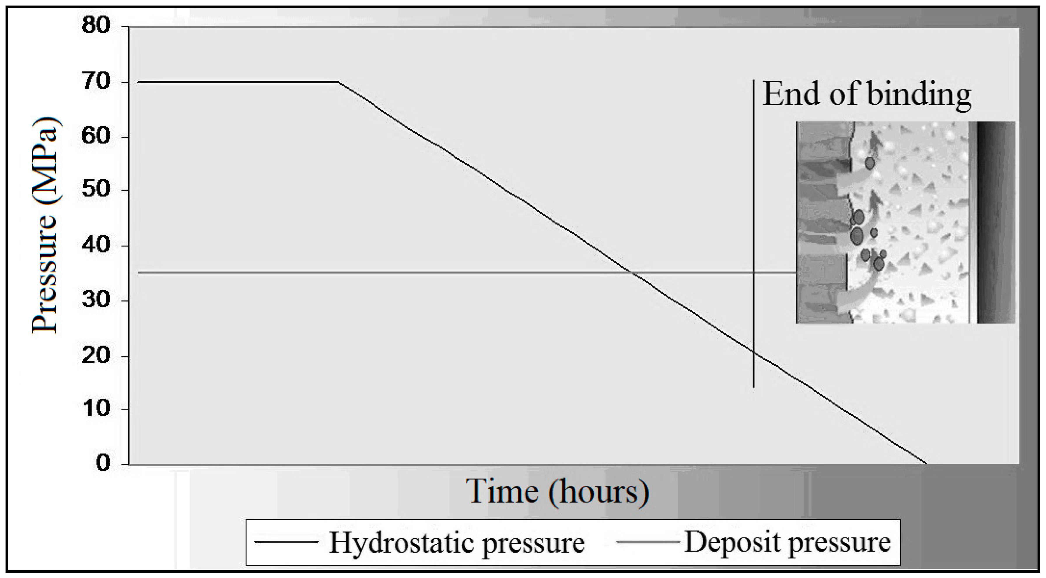
Achieving the end of the slurry bonding before the hydrostatic pressure drops below the formation pressure; reducing the possibility of gas intrusion into the structure of the bonding slurry (
Figure 3). Apparatus from
Figure 4 was used for measurements.
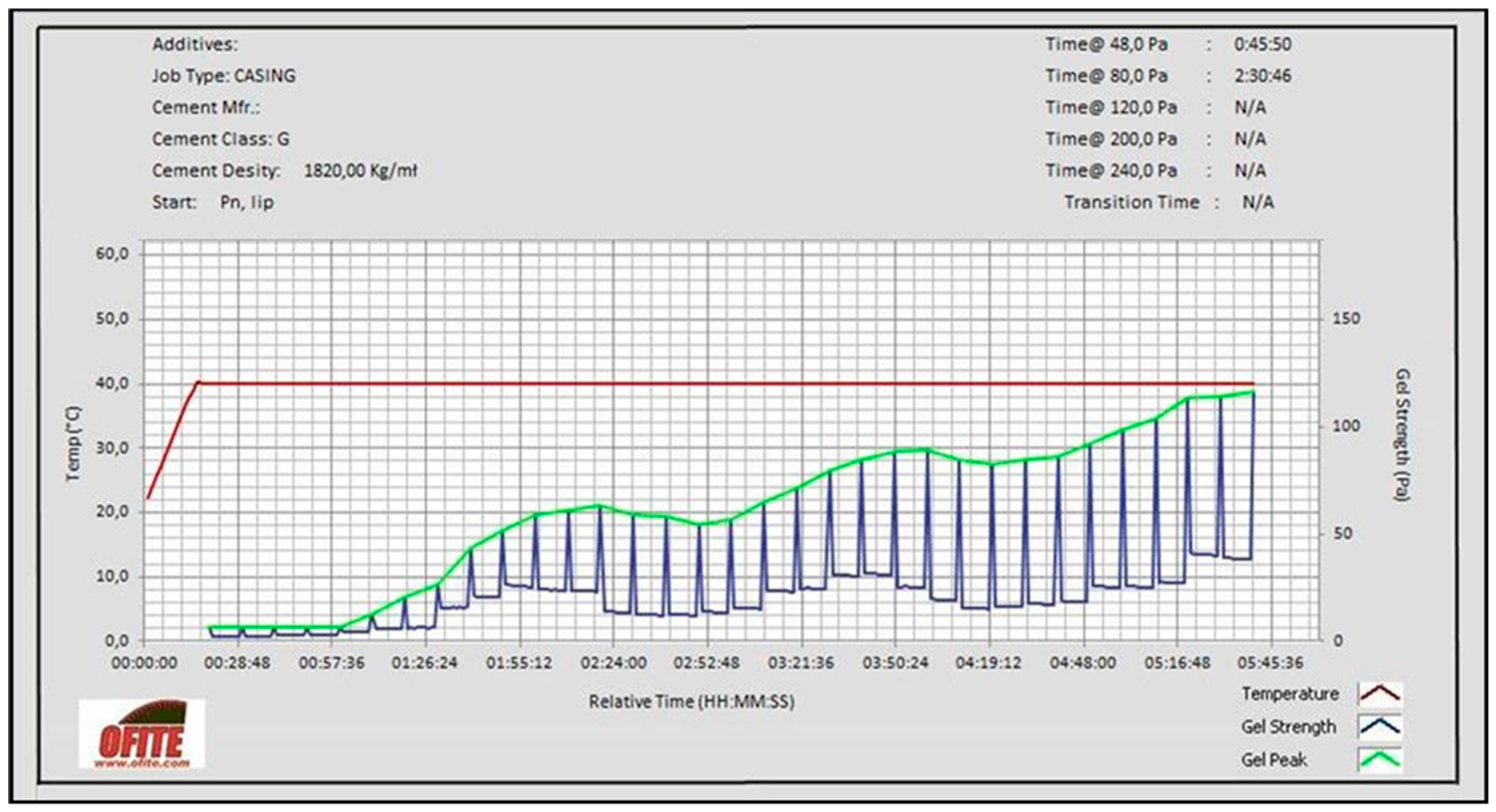
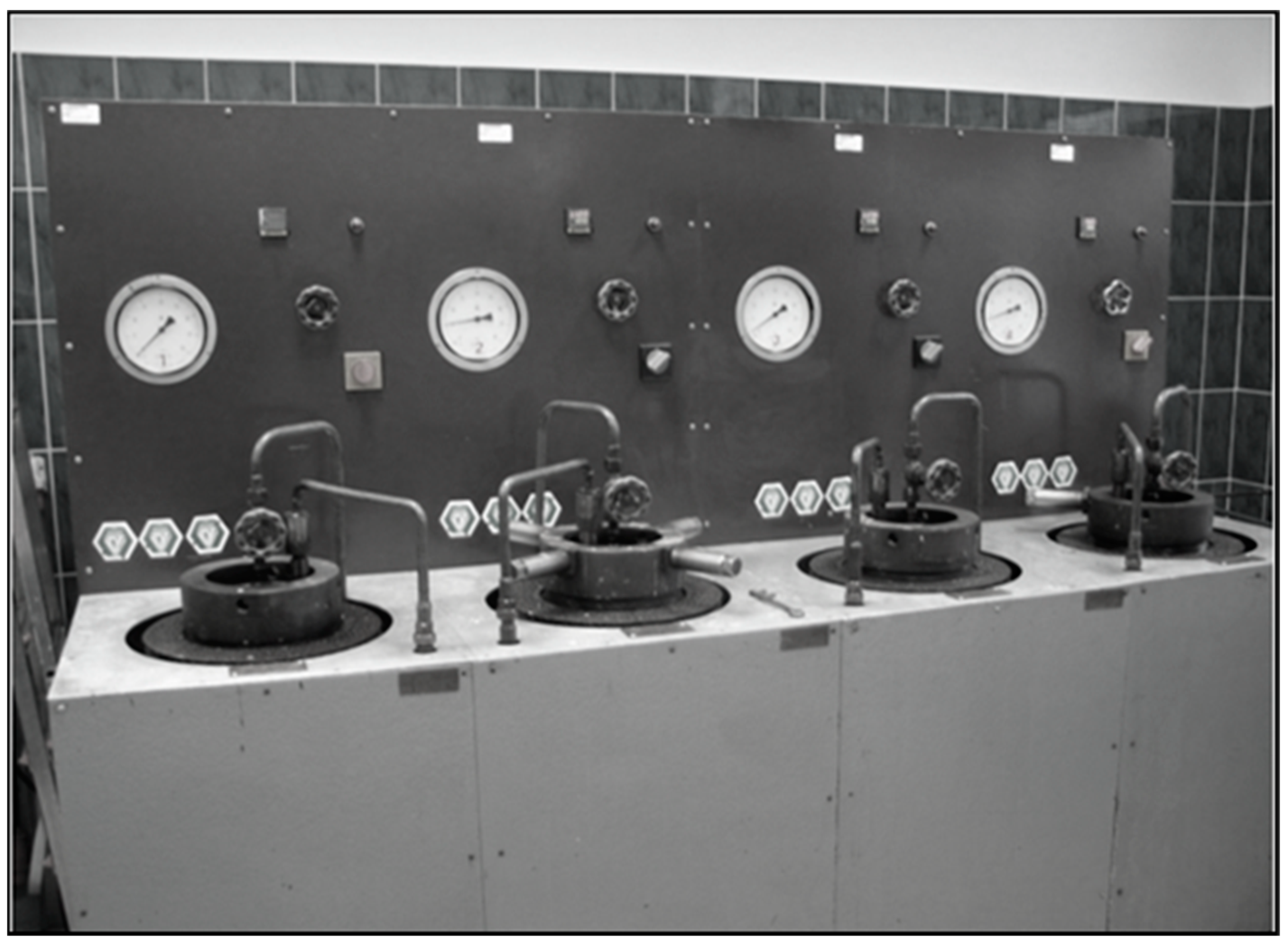
Ensuring the shortest possible transition time from 50 Pa to 250 Pa during the build-up of the static structural strength of the slurry (
Figure 5). This results in the tightening of possible gas channels in the structure of the bonding slurry [
3,
9,
12,
14,
18]. The apparatus from
Figure 6 was used for measurements.
When developing sealing slurry formulations, various additives and admixtures are used in order to reduce the possibility of uncontrolled gas flows in boreholes through the setting slurry and after it has set, i.e., microcements, microsilicas, nanosilicas, which tighten the microstructure, as well as latex and cationic polymers, which shorten the gelling time of the slurry and thus reduce the possibility of natural gas flowing through the hardened cement slurry [
2,
13,
21,
22,
23,
24].
4. Research Findings
Laboratory tests conducted by the Oil and Gas Institute, the National Research Institute and AGH University of Science and Technology show significant differences in effectiveness of removing uncontrolled gas outflows as a result of comparing technological parameters of the base slurry, on the one hand, and the slurry after modification with selected additives and admixtures, on the other.
Table 1 shows the control slurry formulation (Contr slurry) and the modified formulation (Mdf slurry). The technological parameters of the fresh slurries are summarised in
Table 2. There was a significant reduction in the filtration of the slurry from a value of 150 cm
3/30 min to just over 2 cm
3/30 min. The values of rheological parameters have also decreased. In order to minimise the possibility of uncontrolled gas outflows at the contact between the cement coating—rock formation and the cement coating—casing pipes, the presence of gravitational water was eliminated. The changes made to the slurry formulations result in short thickening times from 30 Bearden Consistency units (Bc) to 100 Bc, thus minimizing the occurrence of gas migration during slurry bonding.
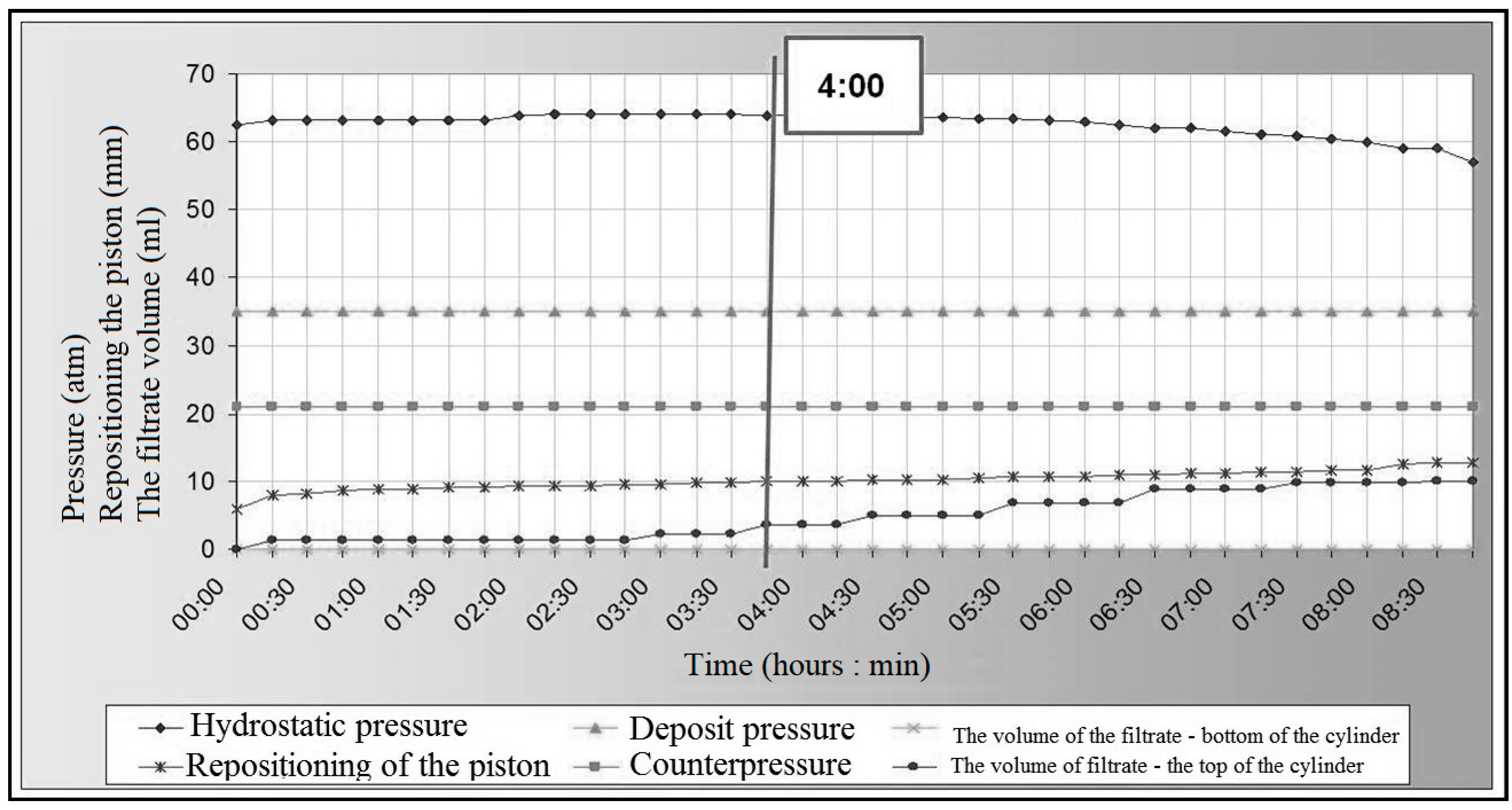
Figure 7 and
Figure 8 show the gas migration test and static structural strength build-up tests for the control slurry. This slurry obtained the end of bonding time after lowering the hydrostatic pressure value below the formation pressure. The consequence of this can be gas intrusion into the structure of the cement coating and the subsequent creation of gas migration paths. Additionally, a large amount of filtrate in the upper part of the measuring cylinder indicates a low anti-migration efficiency of the slurry in question. During the static structural strength test (
Figure 8), no transition period was obtained from a value of 50 Pa to 250 Pa.
Figure 9 and
Figure 10 show the results of tests on modified slurry which is guaranteed to reduce the possibility of uncontrolled gas flow. This slurry reaches the end of bonding (EB) before the hydrostatic pressure drops below the formation pressure. Thus, it shows a very good ability to maintain the hydrostatic pressure at a high level (
Figure 9). Slurry filtration at the top of the cylinder was low, confirming the effectiveness of this slurry in counteracting gas migration. Furthermore, a short transition time of 52 min from 50 Pa to 250 Pa and a steady increase in structural strength were obtained (
Figure 10).
5. Analysis of the Quality and Durability of the Cement Coating with Regard to the Possibility of Uncontrolled Gas Flows
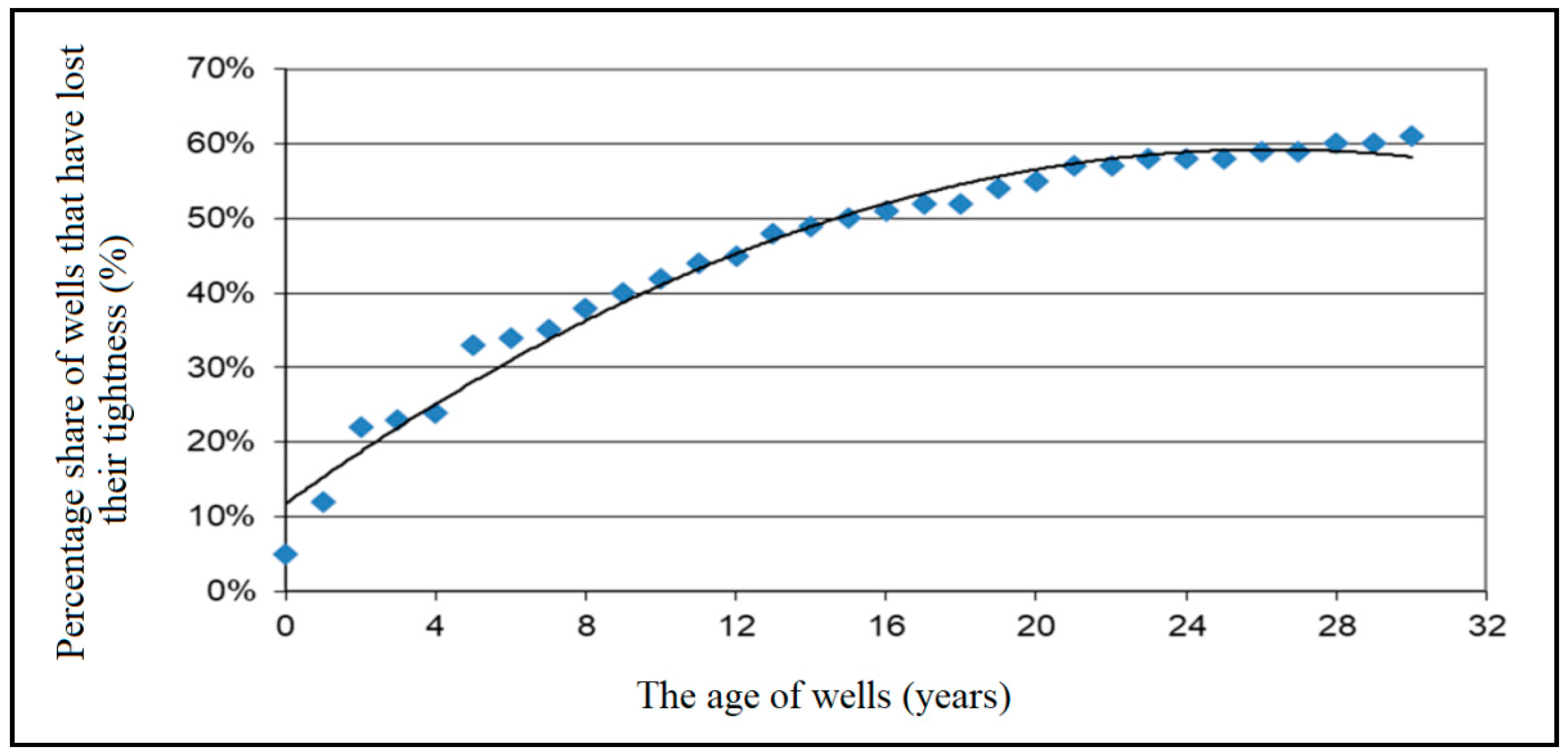
When analysing the problem of gas outflow through the cement coating, corrosion of the hardened slurry in the annular space must also be taken into account. Test results available in the literature indicate that after 30 years, the cement coating has corroded in approx. 60% of the boreholes and deteriorated its tightness, as shown graphically in
Figure 11. The main factors causing corrosion of cement coating in a borehole are formation brine, high temperature and pressure at a given depth [
1,
11]. The combination of this groups of factors results in chemical compounds with reduced mechanical strength and sometimes no bonding ability [
4]. Therefore, in order to design the sealing slurry formulation with improved corrosion resistance, it is necessary to:
The destructive effect of ions present in reservoir brines on hardened cement slurries can be represented by the following chemical reactions [
11,
19,
25]:
Sulphate ions (SO42−) present in the pores of hardened cement slurry cause the formation of salts that are difficult to dissolve. This process is accompanied by a significant increase in the volume of the slurry, and consequently the formation of high tensile stresses in the cement matrix. The swelling compounds formed are gypsum dihydrate and tricalcium aluminate trisulphate hydrate called ettringite.
The hydration products most frequently attacked by sulphate ions are portlandite and C3A and hydrated calcium aluminates:
On the basis of an analysis of long-term laboratory test results on corrosion of hardened cement slurries, the following conclusions can be drawn [
3,
9,
16,
17,
25]:
In order to limit magnesium corrosion, measures are taken to achieve the lowest possible permeability and porosity of the hardened cement slurry, which reduces the penetration of aggressive Mg2+ ions into the cement matrix. Good results are obtained by using mineral additives (primarily granulated blast furnace slag containing small amounts of calcium compounds or fly ash). Therefore, increased resistance to magnesium ion attack is achieved by using metallurgical or ash cements.
Prevention of sulphate corrosion is based on the use of cements with increased resistance to sulphate aggression (mainly High Sulphate Resistant (HSR) type oil well cements). Polymeric additives are also used to create a micro-membrane between the cement grains, as well as fine mineral fillers.
Tests to determine the durability of hardened sealing slurries are based on the following procedures [
9]:
Selection of suitable cement slurry formulations for testing, taking into account borehole conditions.
Preparation of corrosive environments depending on the drilling area.
Preparation of sealing slurry and making of samples of hardened slurries (hardening of samples in autoclaves,
Figure 12).
Exposing the samples to the selected corrosive environments for a defined exposure time.
Periodic visual assessment of samples, photographic documentation and testing of strength, porosity and gas permeability, etc.
Periodic replacement of reservoir brines (every six months).
Samples of hardened slurries are deposited under corrosive conditions for a defined period of time. In autoclaves the temperature reaches 120 °C and the maximum pressure can reach 20 MPa. A reference sample is stored in one chamber of the autoclave in tap water, which represents the reference environment.
Figure 13 shows the values of parameters describing the pore microstructure, while
Figure 14 compares the mechanical parameters of samples 1 and 2. Sample 1 is a hardened cement slurry with very low corrosion resistance. This sample has a porosity factor (ratio of the volume of space between the grains to the volume of the entire sample) of 40.8%, a large proportion of the largest pore spaces, and its mechanical parameters decrease significantly during deposition. This sample deteriorated almost completely after 18 months of deposition under conditions of increased corrosivity. Sample no. 2, which was modified to achieve improved corrosion resistance, has a low share of macropores (
Figure 13), a low porosity index of 28.7% and a high compressive strength, which is almost constant over time.
6. Conclusions
When developing sealing slurries to minimise uncontrolled gas leaks, it is important to modify them at the design stage with additives such as microcement, microsilica, latex, high molecular weight cationic polymers, nanosilica or expansive additives.
The modified formulations discussed in this publication are characterised by appropriate densification times for the given conditions. Such values for the time of thickening allow the slurry to be pumped efficiently into the annular space to be sealed, within the time necessary to carry out the procedure. This time is increased by a safety buffer in the event of complications arising in the preparation of the slurry in the field. The designed cement slurry is characterised by a rapid transition from a consistency value of 30 Bc to a value of 100 Bc during the thickening time test. This short transition time of 10 min goes a long way towards minimising the possibility of gas migration through the binding cement slurry. After injection, the slurry begins to gel and a gas-impermeable cement sheath is formed. The designed slurry with anti-migration properties also has the required rheological parameters, which allow it to be pumped efficiently into the cemented annular space, and to efficiently displace the drilling fluid previously present in the borehole. The newly developed slurry for cementing boreholes with an increased risk of gas migration has a low filtration value and does not show any water retention. As a result, the setting and thickening time is maintained at the required level, because the slurry does not “give off” water in the absorption zones that are often found in the area where gas migration occurs. In addition, a slurry with low filtration and no water retention has a homogeneous structure in the liquid state and does not fractionate. The slurry designed for sealing gas wells is resistant to gas migration during setting, as confirmed by the Static Gel Strength Measurement (SGSM) test. With a transition time of 52 min, it can be concluded that the gas will not be able to penetrate the structure of the cement slurry once it is injected.
When analysing the results of tests on the structure of the cement sheath made of slurry with increased resistance to gas migration, it is found that such a formulation has a significantly lower porosity than standard slurries, and a smaller proportion of pore spaces with the largest diameters. Such conditions confirm the required sealing of the borehole and the elimination of microflows through the cement sheath structure. The mechanical strength values obtained for 18 months of deposition under borehole conditions confirm the erosion resistance of the designed slurry. The samples have comparable strength throughout the storage period, with strengths of over 25 MPa. In contrast, the strength of the control sample decreased due to erosion. The strength of this control sample decreases until, after a final period of exposure to erosive conditions, the sample is destroyed.
Long-term tests of changes in mechanical strength, gas permeability, porosity and microstructure are very important in designing an anti-migration slurry. Such tests allow an objective assessment of the course of destructive processes occurring in the cement sheath during long-term exposure in borehole conditions. Research into the durability of hardened cement slurries is required to improve formulas and develop new slurries for sealing boreholes in various geological and technical conditions.
Author Contributions
Conceptualization, M.K.; methodology, M.K.; validation, R.W. and S.S.; formal analysis, R.W. and S.S.; investigation, M.K., R.W. and S.S.; resources, M.K., R.W., S.S. and G.O.; data curation, R.W.; writing—original draft preparation, R.W.; writing—review and editing, G.O.; visualization, S.S.; supervision, S.S.; project administration, M.K., R.W. and S.S.; funding acquisition, M.K. All authors have read and agreed to the published version of the manuscript.
Funding
The paper was financially supported by Ministry of Science and Higher Education Warsaw (Internal order Oil and Gas Institute—National Research Institute Project No. 0015/KW/21).
Data Availability Statement
Not applicable.
Conflicts of Interest
The authors declare no conflict of interest.
References
- Aadnoy, B.S.; Cooper, I.; Miska, S.Z.; Mitchell, R.F. Advanced Drilling and Well Technology; Society of Petroleum Engineers: Richardson, TX, USA, 2009. [Google Scholar]
- Irawan, S.; Kalwar, S.A.; Abbas, G.; Kumar, S. An Innovative Solution for Preventing Gas Migration through Cement Slurry in the Lower Indus Basin of Pakistan. In Proceedings of the Offshore Technology Conference Asia, Kuala Lumpur, Malaysia, 20–23 March 2018. [Google Scholar]
- Kremieniewski, M.; Rzepka, M.; Stryczek, S.; Wiśniowski, R. Comparison of gas migration test and building structural strength of slurry in the aspect of limiting gas invasion. AGH Drill. Oil Gas 2016, 33, 595–608. Available online: http://journals.bg.agh.edu.pl/DRILLING/2016.33.3/drill.2016.33.3.595.pdf (accessed on 13 July 2021). [CrossRef] [Green Version]
- Stryczek, S.; Gonet, A. Kierunki ograniczania migracji gazu z przestrzeni pierścieniowej otworu wiertniczego. WUG 2005, 3, 10–13. (In Polish) [Google Scholar]
- Tao, C.; Rosenbaum, E.; Kutchko, B.G.; Massoudi, M.A. Brief Review of Gas Migration in Oilwell Cement Slurries. Energies 2021, 14, 2369. [Google Scholar] [CrossRef]
- Kremieniewski, M. O konieczności prowadzenia serwisowych badań parametrów technologicznych zaczynów uszczelniających. Nafta Gaz 2019, 1, 48–55. [Google Scholar] [CrossRef]
- Kremieniewski, M.; Rzepka, M. Poprawa szczelności płaszcza cementowego za pomocą innowacyjnych dodatków antymigracyjnych. Nafta Gaz 2018, 6, 8–15. [Google Scholar] [CrossRef]
- Kremieniewski, M. Receptura zaczynu lekkiego do uszczelniania otworów w strefie niskich ciśnień złożowych. Nafta Gaz 2020, 9, 577–584. [Google Scholar] [CrossRef]
- Kremieniewski, M. Recipe of Lightweight Slurry with High Early Strength of the Resultant Cement Sheath. Energies 2020, 13, 1583. [Google Scholar] [CrossRef] [Green Version]
- Lavrov, A.; Torsaeter, M. Physics and Mechanics of Primary Well Cementing; Springer: Berlin/Heidelberg, Germany, 2016; pp. 9–62. [Google Scholar]
- McLean, R.H.; Manry, C.W.; Whitaker, W.W. Displacement Mechanics in Primary Cementing; Society of Petroleum Engineers: Richardson, TX, USA, 1966; Volume SPE 1488. [Google Scholar]
- Rogers, M.J.; Dillenbeck, R.L.; Eid, R.N. Transition time of cement slurries, definitions and misconceptions, related to annular fluid migration. In Proceedings of the SPE Annual Technical Conference and Exhibition, Houston, TX, USA, 26–29 September 2004; Society of Petroleum Engineers: Richardson, TX, USA, 2004. [Google Scholar]
- Velayati, A. Gas migration through cement slurries analysis: A comparative laboratory study. IJMGE Int. J. Min. Geo Eng. 2015, 49, 281–288. [Google Scholar]
- Kremieniewski, M. Ultra-Lightweight Cement Slurry to Seal Wellbore of Poor Wellbore Stability. Energies 2020, 13, 3124. [Google Scholar] [CrossRef]
- Kremieniewski, M. Analiza parametrów technologicznych wybranych zaczynów lekkich stosowanych do uszczelniania płytkich otworów o temperaturze do 45 °C. Nafta Gaz 2020, 10, 710–718. [Google Scholar] [CrossRef]
- Kotwica, Ł.; Chorembała, M.; Kapeluszna, E.; Stępień, P.; Deja, J.; Illikainen, M.; Gołek, Ł. Effect of metakaolinite on properties of alkali activated slag materials. Key Eng. Mater. 2018, 761, 69–72. Available online: https://www-1scientific-1net-1mc29xjjl31e7.wbg2.bg.agh.edu.pl/KEM.761.69.pdf (accessed on 13 July 2021). [CrossRef]
- Kremieniewski, M.; Stryczek, S.; Wiśniowski, R.; Rzepka, M.; Gonet, A. Influence of bentonite addition on parameters of fresh and hardened cement slurry. AGH Drill. Oil Gas 2017, 34, 335–348. Available online: http://journals.bg.agh.edu.pl/DRILLING/2017.34.2/drill.2017.34.2.335.pdf (accessed on 13 July 2021). [CrossRef] [Green Version]
- Mitchell, R.F.; Miska, S.Z. Fundamentals of Drilling Engineering; SPE 2011 Textbook Series; Society of Petroleum Engineers: Richardson, TX, USA, 2011; Volume 12. [Google Scholar]
- Nelson, E.B.; Guillot, D. Well Cementing; Schlumberger Educational Service: Houston, TX, USA, 1990. [Google Scholar]
- Stryczek, S.; Wiśniowski, R.; Gonet, A.; Złotkowski, A. The influence of time of rheological parameters of fresh cement slurries. AGH Drill. Oil Gas 2014, 31, 123–133. [Google Scholar] [CrossRef]
- Kremieniewski, M. Wpływ drobnoziarnistej krzemionki na parametr czasu oczekiwania na cement—WOC. Nafta Gaz 2019, 11, 683–690. [Google Scholar] [CrossRef]
- Kremieniewski, M. Korelacja skuteczności działania środków dyspergujących o różnym mechanizmie upłynniania. Nafta Gaz 2020, 11, 816–826. [Google Scholar] [CrossRef]
- Kremieniewski, M. Influence of Graphene Oxide on Rheological Parameters of Cement Slurries. Energies 2020, 13, 5441. [Google Scholar] [CrossRef]
- Kremieniewski, M.; Stryczek, S. Zastosowanie cementu wysokoglinowego do sporządzania zaczynów uszczelniających w technologiach wiertniczych. Cement. Wapno Beton 2019, 3, 215–226. [Google Scholar]
- Kremieniewski, M.; Rzepka, M.; Stryczek, S.; Wiśniowski, R. Microstructure of porous space in cement sheath used for sealing oil wells. AGH Drill. Oil Gas 2018, 35, 433–442. Available online: http://journals.bg.agh.edu.pl/DRILLING/2018.35.3/drill.2018.35.3.433.pdf (accessed on 13 July 2021).
- SPE. ATW: Cementing the interface—Best practices and techniques, Moscow, 15–17 November 2004.
| Publisher’s Note: MDPI stays neutral with regard to jurisdictional claims in published maps and institutional affiliations. |
© 2021 by the authors. Licensee MDPI, Basel, Switzerland. This article is an open access article distributed under the terms and conditions of the Creative Commons Attribution (CC BY) license (https://creativecommons.org/licenses/by/4.0/).


