Article

Performance Analysis of a Printed Circuit Heat Exchanger with a Novel Mirror-Symmetric Channel Design

1
Department of Aeronautics and Astronautics, National Cheng Kung University, Tainan 701, Taiwan
2
Research Center for Smart Sustainable Circular Economy, Tunghai University, Taichung 407, Taiwan
3
Department of Mechanical Engineering, National Chin-Yi University of Technology, Taichung 411, Taiwan
4
Lee Kong Chian Faculty of Engineering and Science, Tunku Abdul Rahman University, Kajang 43000, Malaysia
5
International Master Degree Program on Energy Engineering, National Cheng Kung University, Tainan 701, Taiwan
*
Author to whom correspondence should be addressed.
Submission received: 31 May 2021 / Revised: 27 June 2021 / Accepted: 8 July 2021 / Published: 14 July 2021
(This article belongs to the Special Issue Green Energy Technology)

Abstract

:
The printed circuit heat exchanger (PCHE) is a promising waste heat recovery technology to improve energy efficiency. The current investigation presents the experimental results on the thermal performance of a novel PCHE for low-temperature waste heat recovery. The novel PCHE was manufactured using precision machining and diffusion bonding. The thermal performances, such as effectiveness and NTU values at different temperatures, are evaluated, and water is used as a working fluid. The experimental results indicate that the PCHE’s effectiveness is around 0.979 for an inlet flow temperature of 95 °C. The predominant factors affecting the thermal performance of the PCHE are the inlet flow temperature and the flow rate of the working fluid. In addition, a comparison of the experimental results and the literature shows that the effectiveness of the PCHE is better than the others, which have fewer layers of PCHE fins.

1. Introduction

Waste heat generation is inevitable during energy utilization in an industrial process and grows evidently alongside global industrialization. Industrial waste heat is categorized into three temperature ranges, namely: low-temperature (<230 °C, e.g., paper, textile, food processing industry, etc.), medium-temperature (230–650 °C, e.g., ceramic and cement industry, etc.), and high-temperature (>650 °C, e.g., steel and metal processing industry, etc.) [1]. Half of input energy is lost in different forms of waste heat into its surroundings [2], wherein the low-temperature range accounted for about 66% of the total waste heat generated [3,4]. Globally, low-temperature waste heat from industrial activities was extensively observed; for example, roughly 34% was generated in Europe, 50% in China, and 60% in the United States [4]. The main application of the print circuit heat exchanger (PCHE) is in a supercritical CO2 (S-CO2) power cycle, which is promising electricity generation using waste heat recovery. This is due to the high efficiency and compact configuration of the PCHE, which reduces the system footprint area [5]. In addition, the heat exchanger can be designed using various fin geometries and working fluids to fulfill the system requirements [6]. Taiwan’s rich geothermal resources have been well-developed as hot springs and are an integral part of the tourism industry. Sodium bicarbonate hot spring (pH value: 6.2~8.6; temp. 60–99 °C) accounts for 70% of hot springs throughout Taiwan. The heat generated from these hot springs could be recovered and shows great potential for low-temperature waste heat recovery from geothermal heat. Taking advantage of this waste heat from low-temperature sources, not only improves energy conversion efficiency, but also reduces harmful emissions. There are many technical applications for waste heat recovery, such as passive waste heat recovery systems for heat pipes [7] and static power generation technology by automotive exhaust with a thermoelectric generation (TEG) system [8]; however, these options are not suitable for the hot springs scenario.
Heat exchangers, such as a linchpin unit, are widely used in waste heat recovery systems, working independently or combined with other systems. Heat exchangers commonly used in the industry still have many issues that need to be addressed. For example, a shell and tube heat exchanger (STHE) and a finned-tube heat exchanger (FTE) require a large space for installation and operation and have a lower distribution of channels within a small space. In addition, for plate heat exchangers (PHE), the plates connected by welding [9] are weaker than the body. In addition, high channel distribution density has contributed to high-pressure drop and high power of the pump is needed. Increasing the area of heat transfer of the heat exchanger flow channel is a good method to improve heat recovery, but it will incur a high-pressure drop, thus, energy consumption during operation is also increased [10,11]. For low-temperature waste heat recovery, the temperature difference between the heat source and the heat collector is too small to recover, thus, low-temperature waste heat recovery is always harder than middle and high temperatures. Hence, there is less low-temperature waste heat recovery technology in industrial applications using a heat exchanger and the technology is immature compared to other types of waste heat recovery technologies.
A diffusion bonding application is viewed to be a suitable technology for the fabrication of a PCHE. It is a bonding method wherein the gap between the two materials is within an atomic level. This makes the device approximately one body without adding materials. Printed circuit heat exchangers (PCHEs) are high-integrity and density-compact heat exchangers [12]. Due to diffusion bonding technology, the strength and properties of the entire PCHE are unified, and the endurance to stress is excellent. The heat exchanger is well compacted and the channels are densely distributed. Particularly, the design using microchannels offers a better heat transfer performance [13]; however, it is accompanied by a large pressure drop. On the other hand, diffusion bonding technology can offer various advantages [14], such as the reduction of unpredictable risks, such as leakage and malfunctions in service. In addition, the lifetime of heat exchangers fabricated through diffusion bonding is longer than others. Most recent studies focused on carbon dioxide and helium as the working supercritical fluid as well as geometry designs of the channel [15,16,17,18], or applying PCHE technology as the heat exchanger for a Brayton cycle and using a nanofluid as a working fluid [19,20]. Most of the temperature conditions are medium or high temperatures and only a few examples are in low-temperature regions, as shown in Table 1 [5,21,22,23,24,25,26,27,28].
The above literature shows that few studies focused on heat transfer performance and efficiency of PCHEs with water as a working fluid for waste heat recovery at low-temperatures. In view of this, this work aims to design a novel PCHE for low-temperature application fields, especially for hot springs. In this study, bezels are designed on the flow plates to increase heat exchange efficiency. Each bezel is arranged at an interval and with a mirror design for the cold and hot fluid flow plates. The current arrangement of the flow channel in the flow plates will keep the fluid flow in the special flow direction through a bezel. On the other hand, the mirror-symmetric design of the channel in the fluid flow plates is to improve heat exchange performance. Furthermore, the microchannel design is applied to the runner plates to increase the area of heat transfer and thus improve the overall efficiency of the PCHE. Although increasing the fin density will lead to an increase in pressure drop, this effect can be ignored as the current PCHE is targeted at hot-spring waste heat recovery, which does not require any pump for operation. This study investigated the relationship between the heat transfer and flow rate for the PCHE, with a particular focus on different inlet temperatures, flow rate ratio, and heat exchanger effectiveness. In addition, the performance of using precision machining manufacturing runner microchannels under various flow rates and temperature profiles is also investigated. Lastly, a comparison of the current PCHE with other heat exchangers is made, where an etching manufacturing method is used to fabricate the flow channel. This will enhance our understanding of the PCHE performance fabricated using a low-cost manufacturing method and, in return, contribute to the future development of PCHEs for special applications.

2. Materials and Methods

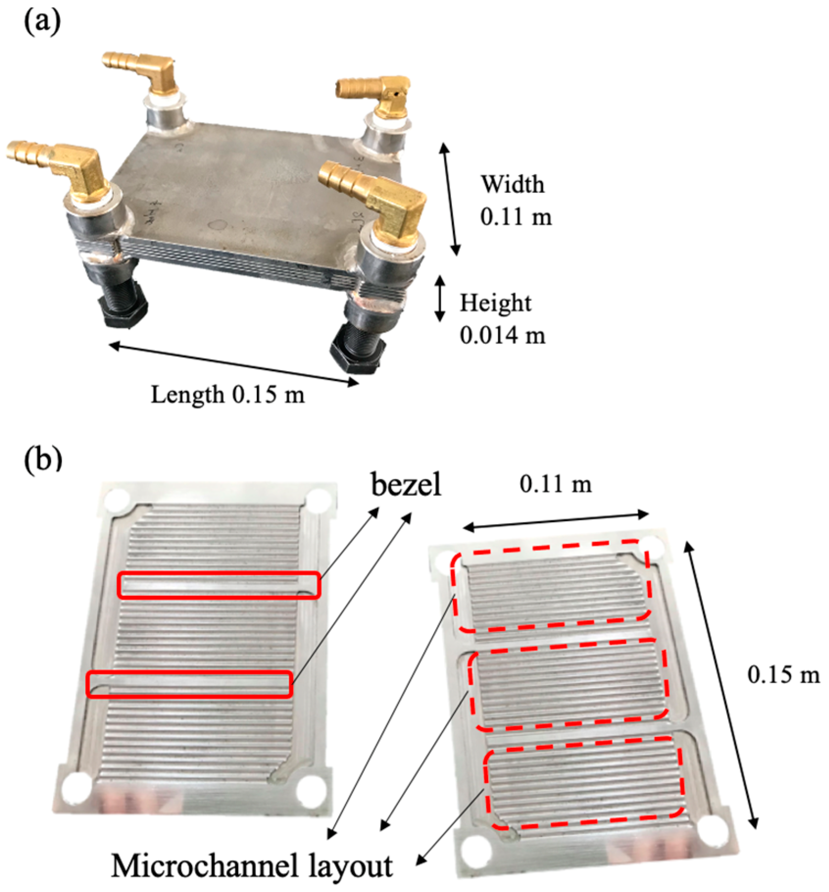
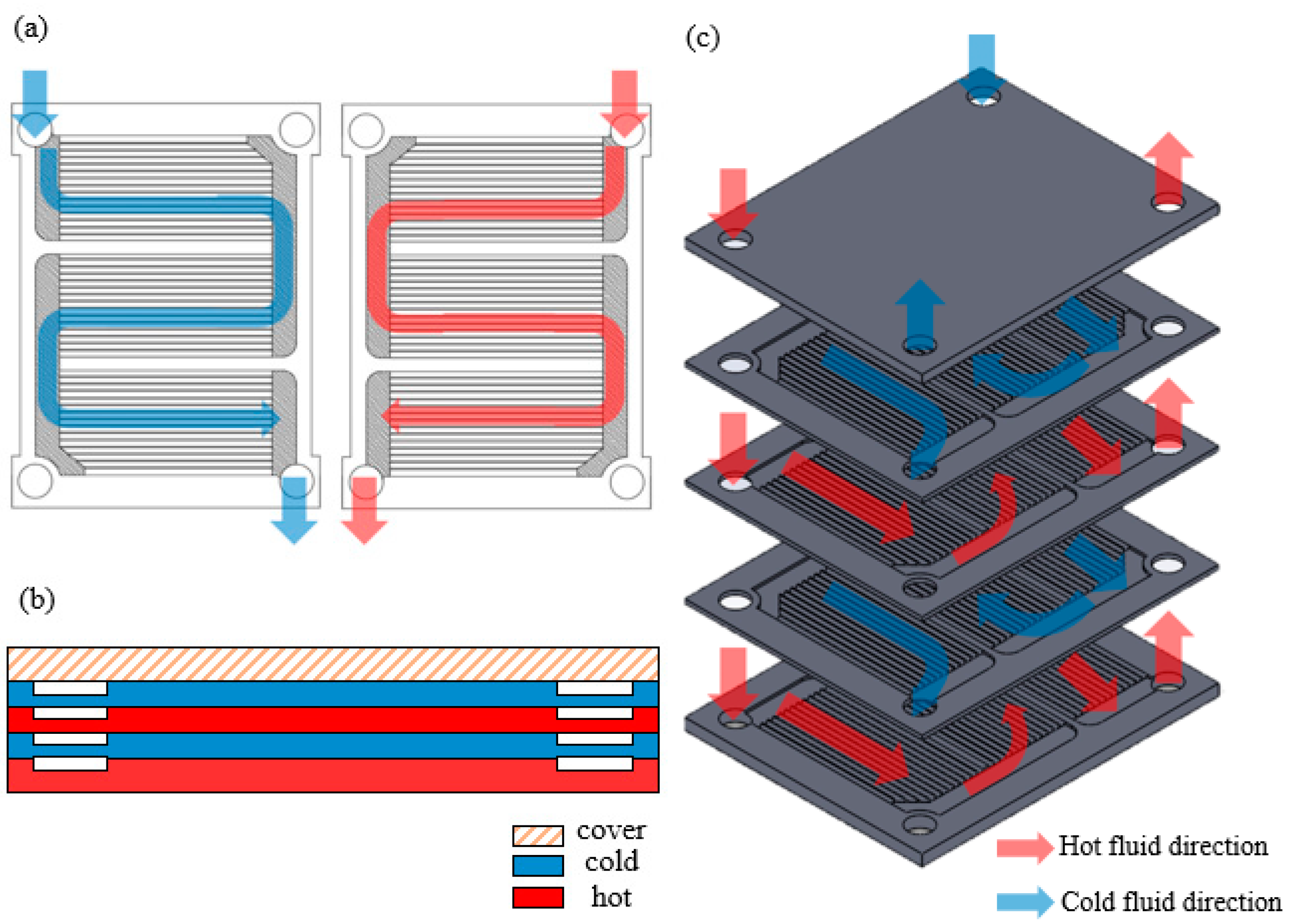
2.1. Design and Manufacture of PCHE

The printed circuit heat exchanger (PCHE) used in this research consisted of four flat stainless steel plates: two hot plates and two cold plates with lengths, widths, and heights of 0.11 m, 0.145 m, and 0.012 m, respectively, as shown in Figure 1a,b. The rectangular channels had a hydraulic diameter of 0.0021 m and were manufactured using precision machining. The flow area of the plate was divided into three zones. The first sone was the three-channel areas in the plate composed of 13 channels. The second zone was the four pool areas at the side of the channel areas. The channel was designed to guide the fluid flow path turn at 180 degrees to the next channel. The last zone had two baffles with a 0.003-m width on the plate, which guided the flow and separated the channel areas and the aforementioned configuration of the channel. Therefore, the working fluid flowed on the plate in an S-shape. This design was to ensure that each channel was fully filled with working fluid and extended the staying time for the fluid in the flow plate. Moreover, hot and cold fluid plates showed symmetric geometry to increase the area of heat transfer [29].
According to the literature, a high compactness and channel distribution density in the PCHE will improve the overall efficiency [12]. The flow directions of cold and hot fluids and the configuration of the PCHE are shown in Figure 2. During the manufacturing process, the stacked plates, including four runner mirror-symmetrically plates and a top plate with a thickness of 0.004 m, were put in a vacuum (10−3 tor) with a working temperature of 1045 °C. The function of the top plate was to protect the PCHE channels from damage during the pressurization process. Next, the plates were subjected to a pressure of 200 bar in the vertical direction to ensure that the distance between the two plates achieved the atomic distance, while cooling down to the surrounding temperature. The fluid flow direction is illustrated in Figure 2c, in which the blue and red arrows represent the cold and hot fluid flows, respectively. After the fluids enter the PCHE, they go into each channel of the plate and then go out. In order to ease the testing of the PCHE, the screw holes at the edge of the plate were designed with a diameter of 0.012 m to facilitate the installation of a 0.375 inch copper joint. Then, heat-resistant silicone hoses were installed on the inlet and outlet of the PCHE.

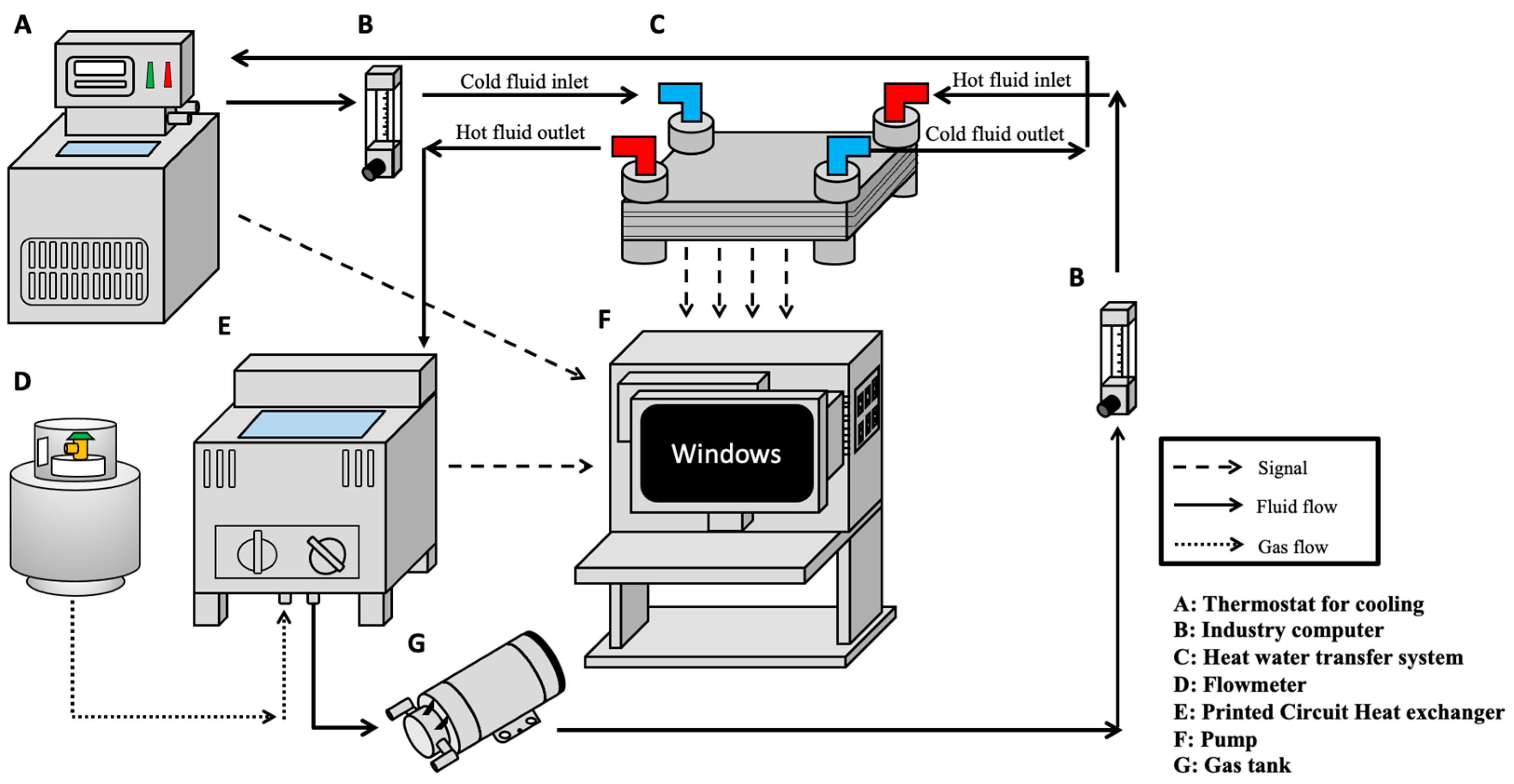
2.2. Experiment Setup

The experimental apparatus and setup to measure and calculate the thermal performance of the PCHE is described in Figure 3, which consists of water as the hot and cold working fluids, two flow meters (Shuang Huan, Taiwan, DK800-6) with adjustable valves installed on the hot fluid and cold fluid circulating loop, refrigerated circulating bath (Yih Der, Tainan, Taiwan, BL710-D), pump (HITON, Tainan, Taiwan, HF-8006) and a 40-L water heating system powered by liquified petroleum gas (Ta-Han, Tainan, Taiwan, BDF-23C). The temperatures were measured using eight K-type thermocouples (Chuan Yu, Kaohsiung, Taiwan, K type) connected to an industrial computer, equipped with a thermocouple slot module. Filters were installed at the outlet of the sink and the water heating system to remove impurities in the working fluid and prevent damage to the flow meter. Since the flow layout was set to be in a counterflow, the counterflow pattern was adopted in the flow configuration [30], which resulted in a high effectiveness, where the cold inlet was on the opposite side of the hot inlet. It is also shown in Figure 3 that the flow rate passing through the flowmeters was controlled by a valve; the maximum mass flow rate was 100 L/h. The hot working fluid was driven by a pump and the temperature of the fluid was controlled by a heater. A constant-temperature cold working fluid was supplied by a refrigerated circulating bath to the test rig. The thermocouples were installed at the inlet and outlet of both fluids and inside the tube of the copper joint. They were about 0.001 m away from the entrance of the PCHE. Before performing experiments, the thermocouples were calibrated to an accuracy of ±0.01 °C. In addition, the water heating system had thermocouples to accurately monitor and control the temperature. Finally, all piping system and PCHE were insulated with thermal insulation wool to minimize heat loss.

2.3. Operations and Data Analysis of Experimentations

Three different hot fluid inlet temperatures, 75 °C, 85 °C, and 95 °C, were used in this study. The inlet temperature of the cold fluid (water) was 20 °C. The range of the cold and hot fluids’ flow rates were 0.1667–1.667 L/min (i.e., 10–100 L/h), they were adjusted by the valve on the flowmeter. This corresponds to the Reynolds numbers of 50–514. The Reynolds number (Re) was calculated in Equation (1) in light of the method suggested by Cowell [31]. The average convective heat transfer coefficient (h) and Nusselt number (Nu) were obtained using Equations (2) and (3) as [9]:
Re = ρ V D h μ
h = ( m ˙ c p Δ T ) h o t A   ( T s T )
Nu = h D h k
In Equation (1), Dh (0.0021 m) is the hydraulic diameter, V is the velocity of the fluid, μ is the dynamic viscosity of the fluid, and ρ is the density of the fluid. In Equation (2), the product in the numerator is the heat flux of hot fluid, including cp (specific heat), m ˙ (flow rate), and ΔT (the temperature difference between the inlet and outlet), respectively. In addition, T s and T are the temperature of channel surface and fluid temperature, respectively. In Equation (3), k represents the thermal conductivity.
The effectiveness ( ε ) of the PCHE [9] is assessed as the ratio of the actual heat transfer rate ( Q a c t u a l ) to the theoretical maximum rate of the heat transfer ( Q m a x ) and is expressed using the equation below:
ε = Q a c t u a l Q m a x = C h o t   ( T h , i n T h , o u t ) C m i n   ( T h , i n T c , i n ) = ( m ˙   c p ) h o t   ( T h , i n T h , o u t ) ( m ˙   c p ) m i n   ( T h , i n T c , i n )
In Equation (4), T c , i n , T h , i n , and T h , o u t represent the temperature of the cold inlet, hot inlet, and hot outlet, respectively. C h o t denotes the product of the mass flow and specific heat of the hot and fluid, and C m i n is the smaller one between the cold and hot fluid.
The value of the overall heat transfer coefficient (U) can be calculated from the heat transfer area and the logarithmic mean temperature difference (LMTD) between the hot and cold fluid flows and average heat transfer rate ( Q ˙ a v e r a g e ) by Thulukkanam [9]. They are expressed as follows:
Q ˙ a v e r a g e = Q ˙ h o t + Q ˙ c o l d 2
U = Q ˙ a v e r a g e A t o t a l   L M T D
L M T D = Δ T 1 Δ T 2 L n N (   Δ T 1 Δ T 2   )
where Δ T 1 and Δ T 2 are the temperature difference of the inlet and outlet between the hot and cold working fluid, respectively, as shown below:
Δ T 1 = T h o t , i n l e t T c o l d ,   o u t l e t
Δ T 2 = T h o t , o u t l e t T c o l d ,   i n l e t
The number of transfer units (NTU) value can be calculated by the overall heat transfer coefficient [32], as shown in Equation (10). In the equation, A t o t a l is the total area of heat transfer of the PCHE, C m i n is the smaller one between heat capacity of cold and hot fluid, c p , c is the heat capacity of cold fluid. Similar to other literature analysis, the usual heat exchanger effectiveness ε is defined as the relation function between C r and NTU, as shown in Equation (11) and can be simplified to Equation (12) [33]:
N T U = U A t o t a l C m i n = U A t o t a l ( m ˙ c p , c ) C
ε = 1 e [ N T U ( 1 C r ) ] 1 C r e [ N T U ( 1 C r ) ]
ε = N T U 1 + N T U  
C r = C m i n C m a x

2.4. Uncertainties Analysis

The results of the experiment and its measurements were affected by many factors. Uncertainty analysis was used to make sure that the precision of the measurement device was set before the experiments, and to calibrate and ascertain their accuracies. This included electronic load, flowmeters, and thermocouples. The ranges of measuring or operating, resolution, and uncertainty in measurement is tabulated in Table 2, where uncertainty in the measurement of devices is defined as in Equation (14) [34]:
R e l a t i v e   u n c e r t a i n t y = 0.5 × r e s o l u t i o n   v a l u e   o f   m e a s u r i n g   o r   o p e r a t i n g
Table 2 lists the data for supplying and the deviation analysis of experiments, including temperature, which was controlled between 75 °C and 95 °C and the flow rate was between 10 L/h and 100 L/h. The analysis results of the uncertainty of the measurement due to the equipment was less than 2.5%.

3. Results and Discussion
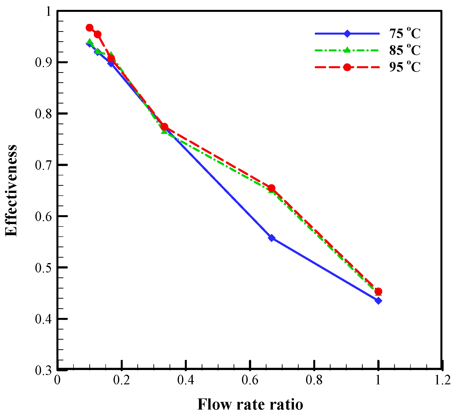
3.1. Effectiveness

Figure 4 illustrates the effectiveness of the PCHE for three different inlet temperatures of the hot fluid flow versus the cold-to-hot fluid flow rate ratio. The effectiveness (ε) can be observed to easily decrease with an increase in flow rate ratio. The effectiveness of the heat exchanger drops by at least 50% when the ratio of flow rate increases from 0.1 to 1, showing the pronounced influence of the ratio of the flow rate on the effectiveness of the PCHE. On the other hand, the differences between the three curves are not significant, revealing that the effect of increasing the inlet temperatures is not as obvious as the flow rate ratio.
In Figure 4, the highest effectiveness of 0.979 was achieved at a flow rate ratio of 0.1 (i.e., the minimum ratio of flow rate), whereas the lowest effectiveness of 0.428 is exhibited at a flow rate ratio of 1, rendering a 53% difference in the effectiveness between the two ratios under the same hot inlet temperature. On account of the higher effective value at a ratio of 0.1, this ratio is suitable for the operation of PCHEs. On the contrary, a flow rate ratio of 1 will lead to poor performance of the PCHE. Overall, the effectiveness of the PCHE under the hot inlet temperature of 95 °C is better than the other two temperatures at a low flow rate ratio. In summary, operating the heat exchanger with high inlet temperature and low flow rate ratio is conducive to intensifying the effectiveness and thereby the heat exchange. Attala et al.’s [35] experimental results on the plate heat exchanger had a similar behavior at a low Reynolds number.

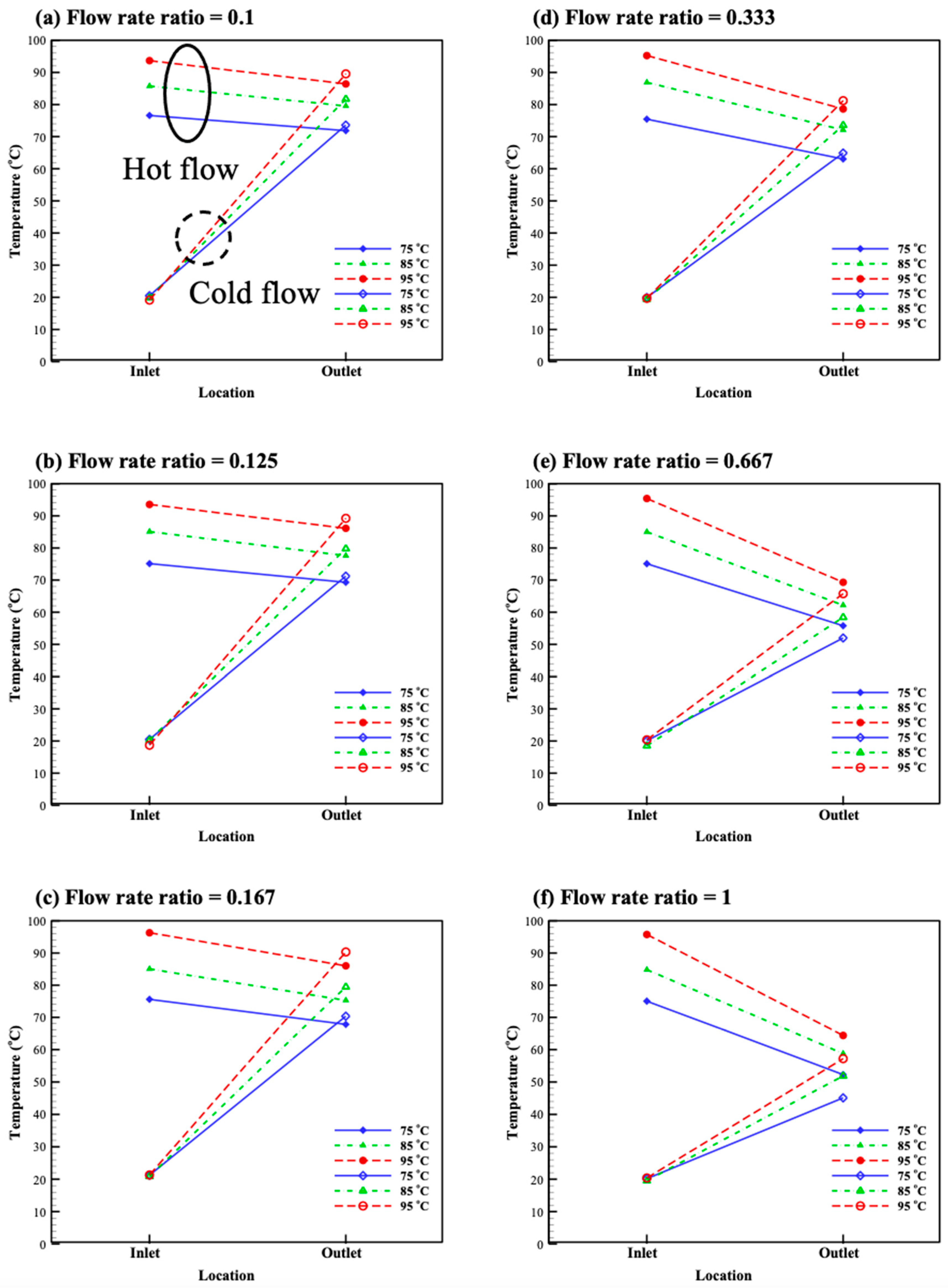
3.2. Temperature Distribution

The temperature distribution of the hot and cold fluid inlet and outlet at three different hot inlet fluid temperatures (75, 85, and 95 °C), along with a fixed cold inlet temperature (20 °C) for different flow rate ratios, are shown in Figure 5. Altering the flow rate ratio causes variations in the temperature of the distribution. At low flow ratios, such as 0.1, 0.125, and 0.167, the temperature slopes of the hot fluid flow are relatively insignificant, whereas the temperature slopes of the cold fluid flow are steeper. This is ascribed to more heat being contained in the hot fluid and relatively less heat being transferred to the cold fluid, stemming from a lower cold fluid flow rate. As a consequence, the temperature variation of the hot fluid flow is small, whereas it is pronounced in the cold fluid flow. On the contrary, at higher flow rate ratios, such as 0.333, 0.667, and 1, the variation in the temperature of the hot fluid flow tends to become obvious, whereas the rising tendency in the temperature of the cold fluid flow becomes less obvious [36]. For the cases of a flow rate ratio of <0.667, it is noteworthy that, after heat exchange, the outlet temperature of the cold fluid flow is always higher than that of the hot fluid flow, whereas an opposite result is observed at flow rate ratio =0.667 and 1. For the two factors of the hot fluid inlet temperature and the flow rate ratio investigated in this study, Figure 5 indicates that the flow rate ratio is more influential on the temperature profile when compared with the hot fluid inlet temperature. Figley et al. [32] explored the correlation between flow rate ratio and hot fluid inlet temperature, which had a similar temperature changing trend, and established the thermal-hydraulic performance in their PCHE numerical model.

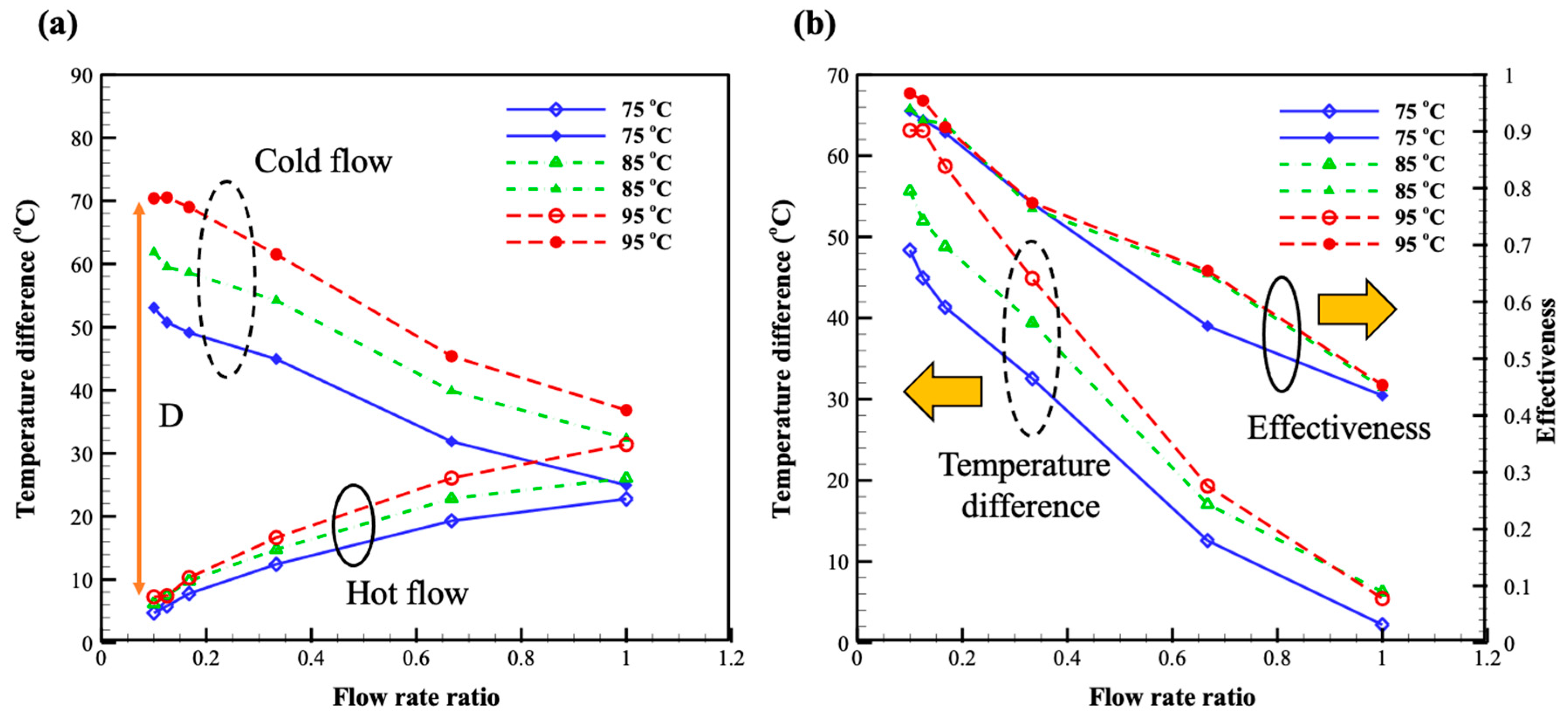
3.3. Temperature Difference and Effectiveness

Figure 6a examines the temperature difference of the cold and hot fluids’ between the inlet and outlet. The temperature difference of the hot fluid between the outlet and inlet decreases with the rising flow rate ratio, but it shows an opposite trend for the cold fluid. Physically, the higher the temperature difference, the better the heat transfer. At low flow rate ratios, the temperature difference of the cold fluid flow is higher which is contributed by a high flow rate of the cold fluid. Thus, the temperature of the cold fluid flow can be easily raised. Meanwhile, the temperature difference in the hot fluid flow is small, which is ascribed to the high flow rate of the hot fluid. It is not surprising that an increase in the hot fluid’s inlet temperature increases the temperature differences of the hot and cold fluids. A past study [37] provided several cross-flow configurations and explained the correlation between the effectiveness and the temperature difference which is in line with the obtained results in the present study.
To further investigate the heat transfer performance, the temperature difference between the cold and hot fluid temperature versus flow rate ratio is shown in Figure 6b. Meanwhile, the profiles of the effectiveness from Equation (12) are also shown in Figure 6b. As a whole, both the D value and effectiveness ( ε ) decrease monotonically with the increase of the flow rate ratio. Physically, the effectiveness is a ratio between the actual heat transfer rate and the maximum (ideal) heat transfer rate. Accordingly, when the effectiveness is larger, the performance of heat transfer is also better. The maximum value of the effectiveness in Figure 6b is 0.979, occurring at a hot fluid flow inlet of 95 °C and the flow rate ratio of 0.1. In contrast, the minimum value of the effectiveness is 0.428 occurring at a hot fluid flow inlet of 75 °C and a flow rate ratio of 1. This indicates that the low flow rate ratio with low cold fluid flow rate and high hot fluid flow rate is a better combination for optimum thermal performance for the PCHE. Overall, the distributions of D and ε showed high correlation.

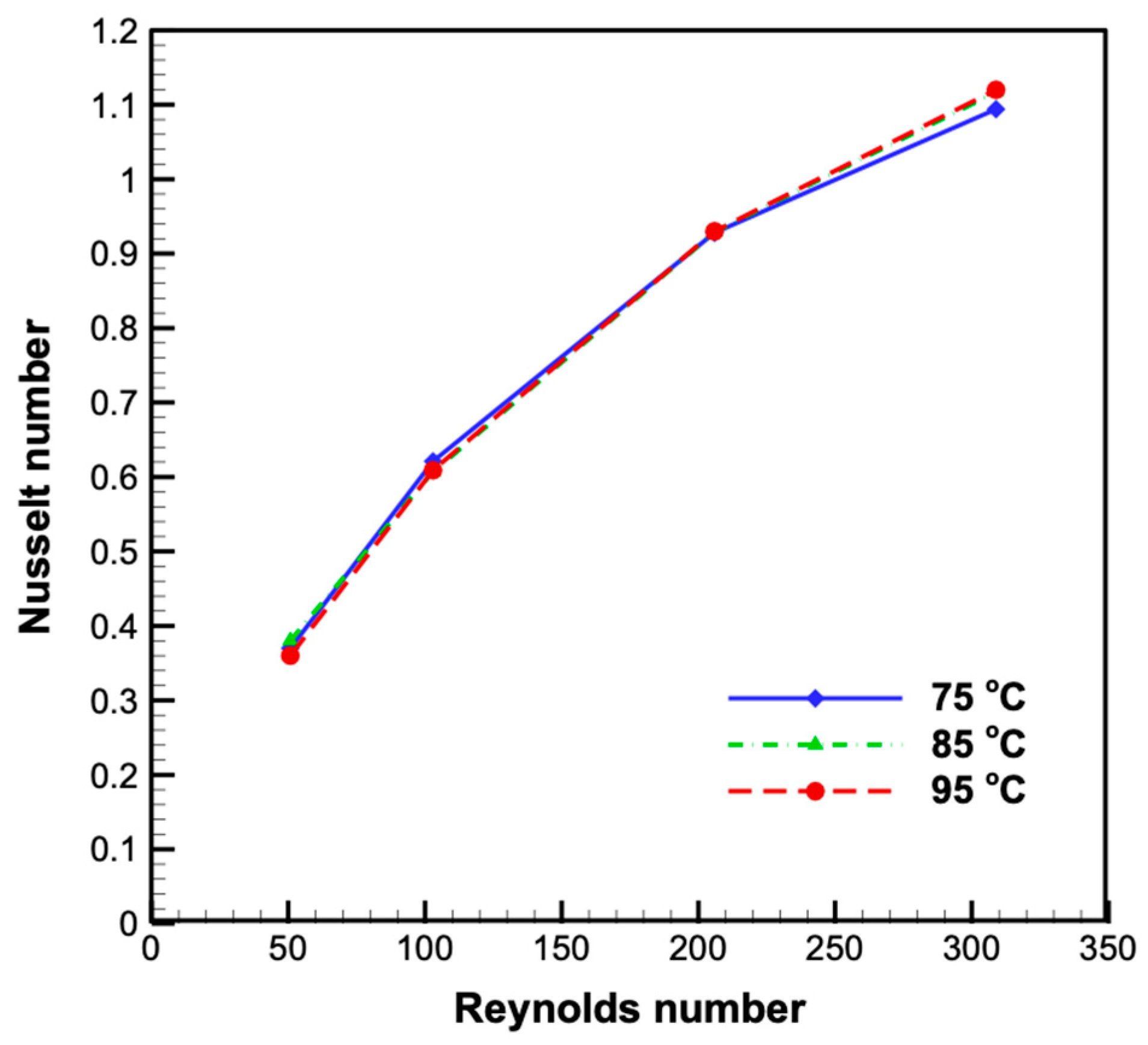
3.4. Characteristics of Heat Transfer Performance

Figure 7 shows the convective heat transfer coefficient of the PCHE under various Reynolds numbers of the cold fluid flows. A higher Reynolds number is conducive to convective heat transfer. A similar behavior was also observed in a previously reported study [38]. This is why there is an increment of convective heat transfer coefficient with a rising Reynolds number. For the hot fluid flow inlet temperature of 95 °C, the heat transfer coefficient value is increased from Re = 50 to Re = 300, rendering an increment of 67.8%, and other conditions of hot inlet temperatures are increasing by at least 64%. At low Re values, such as 50 and 100, the sensitivity of the heat transfer coefficient to the hot fluid flow inlet temperature Re is low and the variation is small. However, at Re = 300, the convective heat transfer coefficient at the hot fluid flow inlet temperature at 95 °C is about 5% higher than that of the convective heat transfer coefficient at the hot fluid flow inlet temperature at 75 °C. The relationship between the effectiveness and the Reynolds number is shown in Figure 7. Unlike the convective heat transfer coefficient, as the Reynolds number increases, the effectiveness shows a downward trend. The convective heat transfer coefficient shows a positive correlation with the Reynolds number of the cold fluid flow where the amount of heat transfer increases. However, the fluid velocity is relatively high and the residence time of the cold fluid in the channel is shorter and reduces the effectiveness of the heat exchanger. The flow plates of PCHE are designed as an S-shape (Figure 1 and Figure 2), which can prolong the residence time of the working fluid. It is obvious that the influence of the residence time prevails over the flow rate. Thus, the effectiveness declines with an increasing Reynolds number. Yan et al. [39] studied the effectiveness values of the different flow rate configurations in which they also observed a similar decreasing trend of the heat exchanger effectiveness with the increasing of the flow rate.
Figure 8 further explores the relationship between the Nusselt number (Nu) and the Reynolds number in the channel. The Nusselt number is proportional to the convective heat transfer coefficient which is a function of the flow rate or Reynolds number. As a consequence, the Nusselt number goes up when the Reynolds number increases, and the entire trend of the Nusselt number curves resembles that of the convective heat transfer coefficient. Yang et al. [38] studied the flow and performance of heat transfer in mini channels configured with hexagonal fins at laminar flow, and obtained a similar heat transfer performance. For the hot fluid flow inlet temperature of 95 °C, the Nusselt number increases by 68% when the Reynolds number increases from 50 to 300. Similar to the convective heat transfer coefficient, the Nusselt number is fairly insensitive to the variation of the hot fluid flow inlet temperature at Re = 50 and 100, while its variation at Re = 300 is also insignificant. This reflects that both the Nusselt number and the convective heat transfer coefficient are mainly governed by the Reynolds number, whereas the hot fluid flow inlet temperature is not affecting the Nusselt number and the convective heat transfer coefficient. To develop the correlation for Nusselt number and Reynold number, the basic logarithm form was used, as follows:
Nu = 0.03428 Re 0.6135

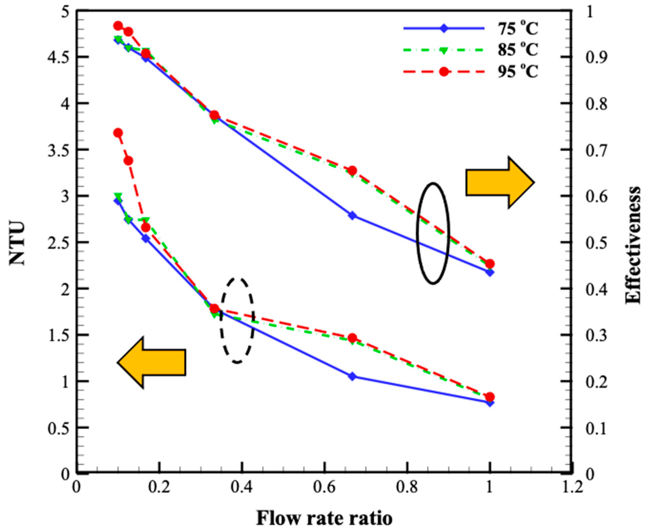
3.5. The Number of Transferred Unit Value (NTU)

The value of the number of transferred unit (NTU) signifies the rate of net heat exchange between two fluids in the PCHE. The profiles of NTU and effectiveness are plotted in Figure 9 to show the relationship between NTU, effectiveness, and flow rate ratio. Both the NTU and effectiveness values decrease with rising flow rate ratios, revealing that the trend of NTU follows the trend of effectiveness. A past simulation study [40] explored the relationship between NTU and effectiveness, and observed that the heat exchanger effectiveness ε and NTU have the same trend in counterflow. When the ratio of flow rate decreases from 1 to 0.1, the NTU value is increased by 70.3% at a low flow rate. These explain that a longer residence time in the PCHE is beneficial to heat transfer. When the Cr value is 1, the values of the effectiveness and NTU with the hot inlet temperature of 95 °C are 0.428 and 0.83, respectively. The calculated effectiveness using Equation (12), in terms of NTU, is 0.453, which is close to the calculated effectiveness using Equation (3), which is 0.428. Sheldon et al. [41] compared the most common estimated efficiency methods for heat exchangers—effectiveness and NTU methods—and mentioned that the two methods were equivalent.

3.6. Comparison to Other Research

This study provides the effectiveness of PCHEs using water as a working fluid at low Reynolds numbers. The experimental results showed that the obtained effectiveness values in this study were between the values of past reported studies, as shown in Figure 10. In past studies, heat exchangers with compact microchannel were constructed and water was used as a working fluid in counterflow at low Reynolds numbers. Hasan et al. [42] studied the influence of channel geometry on the performance of microchannel heat using simulations, where the effectiveness values of the circular and square channels were higher and lower, respectively. The hydraulic diameter was about 24 times smaller than our PCHE. In general, the attained effectiveness in this study is better than that of the Hasan et al. design [42]. On the other hand, the effectiveness of this study is lower than the results of Seyf et al. [43] and Mohammadian et al. [44]. Seyf et al. [43] studied microchannel heat exchangers using simulations. The hydraulic diameter in the study of Seyf et al. [43] was smaller than our PCHE by a factor of around 23 times. This is the reason why their results are better. In the study of Mohammadian et al. [44], they numerically studied nanofluid (Al2O3-water) in a counterflow heat exchanger, which had a better heat transfer performance. The nanofluid could easily increase the cold outlet temperature and make the temperature difference increase, so their results are better than those of the present study.

4. Conclusions

In the present study, a printed circuit heat exchanger (PCHE) is successfully fabricated using precision manufacturing and diffusion bonding. The printed circuit heat exchanger with an S-shaped meandering design for a flow path was tested at laminar flow (50 < Re < 300). The experimental results showed that the printed circuit heat exchanger provides high effectiveness and thermal performance at low flow rate ratios. The highest effectiveness of the PCHE is about 0.979 for an inlet flow temperature of 95 °C. The highest heat transfer coefficient obtained from the experiment is about 347.8 for Re = 300. The waste heat at a hot spring can be effectively harvested through the S-type meandering design of the flow path on the heat exchanger plate. This design will provide a larger heat transfer area and maximize the heat exchange between the fluids. A combination of the multiple flow rate ratios shows the best operating conditions. Regardless of the inlet temperature, the effectiveness of the PCHE is always higher. When the flow rate ratio is 1, the NTU value and effectiveness are about 0.83 and 0.428, respectively. In future work, the printed circuit heat exchanger will be tested under turbulent flow conditions to further characterize its thermal performance.

Author Contributions

Conceptualization, C.-Y.C. and W.-H.C.; methodology, C.-Y.C.; formal analysis, C.-Y.C. and M.C.U.; investigation, C.-Y.C. and M.C.U.; resources, W.-H.C.; data curation, C.-Y.C., W.-H.C. and M.C.U.; validation, C.-Y.C. and M.C.U.; writing—original draft preparation, C.-Y.C. and A.A.A.; writing—review and editing, W.-H.C. and L.H.S.; visualization, C.-Y.C.; supervision, W.-H.C.; funding acquisition, W.-H.C.; Project administration, C.-Y.C. and W.-H.C. All authors have read and agreed to the published version of the manuscript.

Funding

This research was supported in part by Higher Education Sprout Project, Ministry of Education to the Headquarters of University Advancement at National Cheng Kung University(NCKU). The authors also acknowledge the financial support of the Ministry of Science and Technology, Taiwan, R.O.C., under the contracts The authors acknowledge the financial support of the Ministry of Science and Technology, Taiwan, R.O.C., under the contract MOST 109-2622-E-006-006-CC1.

Institutional Review Board Statement

Not applicable.

Informed Consent Statement

Not applicable.

Data Availability Statement

Not applicable.

Acknowledgments

This research was supported in part by Higher Education Sprout Project, Ministry of Education to the Headquarters of University Advancement at National Cheng Kung University(NCKU). The authors also acknowledge the financial support of the Ministry of Science and Technology, Taiwan, R.O.C., under the contracts. The authors acknowledge the financial support of the Ministry of Science and Technology, Taiwan, R.O.C., under the contract MOST 109-2622-E-006-006-CC1.

Conflicts of Interest

The authors declare no conflict of interest.

Nomenclature

AArea of heat transfer (m2)
c p , c Cold work fluid’s heat capacity (J/kg °C)
c p , h Hot work fluid’s heat capacity (J/kg °C)
C m i n Smaller of the two heat capacity rates (J/kg °C)
C h o t Hot fluid’s heat capacity rates (J/kg °C)
D h Hydraulic diameter (m)
h Convective heat transfer coefficient (W/m2⋅°C)
k Thermal conductivity (W/m °C)
NuNusselt number
QHeat transfer rate (W)
qHeat flux (W/m2)
q m a x Large of heat flux (W/m2)
Re Reynold number (W/m2)
TTemperature (°C)
T m Average temperature of hot fluid inlet (°C)
T h , i n Hot fluid inlet temperature (°C)
T h , o u t Hot fluid outlet temperature (°C)
T c , i n Cold fluid inlet temperature (°C)
T c , o u t Cold fluid outlet temperature (°C)
T s channel surface temperature (°C)
T fluid temperature in channel (°C)
Δ T m Temperature difference (°C)
V Velocity (m/s)
m ˙ Mass flow (kg/s)
Greek letters
ε Effectiveness
μ Viscosity (Pa⋅s)
ρ Density (kg/m3)
Subscripts
CCold fluid
HHot fluid
inInlet
outOutlet

References

  1. Papapetrou, M.; Kosmadakis, G.; Cipollina, A.; La Commare, U.; Micale, G. Industrial waste heat: Estimation of the technically available resource in the EU per industrial sector, temperature level and country. Appl. Therm. Eng. 2018, 138, 207–216. [Google Scholar] [CrossRef]
  2. Hung, T.C.; Shai, T.Y.; Wang, S.K. A review of organic Rankine cycles (ORCs) for the recovery of low-grade waste heat. Energy 1997, 22, 661–667. [Google Scholar] [CrossRef]
  3. Zhou, N.J.; Wang, X.Y.; Chen, Z.; Wang, Z.Q. Experimental study on Organic Rankine Cycle for waste heat recovery from low-temperature flue gas. Energy 2013, 55, 216–225. [Google Scholar] [CrossRef]
  4. Xu, Z.Y.; Wang, R.Z.; Yang, C. Perspectives for low-temperature waste heat recovery. Energy 2019, 176, 1037–1043. [Google Scholar] [CrossRef]
  5. Baik, S.; Kim, S.G.; Lee, J.; Lee, J.I. Study on CO2–Water printed circuit heat exchanger performance operating under various CO2 phases for S-CO2 power cycle application. Appl. Therm. Eng. 2017, 113, 1536–1546. [Google Scholar] [CrossRef]
  6. Shi, H.-Y.; Li, M.-J.; Wang, W.-Q.; Qiu, Y.; Tao, W.-Q. Heat transfer and friction of molten salt and supercritical CO2 flowing in an airfoil channel of a printed circuit heat exchanger. Int. J. Heat Mass Transf. 2020, 150, 119006. [Google Scholar] [CrossRef]
  7. Orr, B.; Akbarzadeh, A.; Mochizuki, M.; Singh, R. A review of car waste heat recovery systems utilising thermoelectric generators and heat pipes. Appl. Therm. Eng. 2016, 101, 490–495. [Google Scholar] [CrossRef]
  8. Shen, Z.G.; Tian, L.L.; Liu, X. Automotive exhaust thermoelectric generators: Current status, challenges and future prospects. Energy Convers. Manag. 2019, 195, 1138–1173. [Google Scholar] [CrossRef]
  9. Thulukkanam, K. Heat Exchanger Design Handbook; CRC Press: Boca Raton, FL, USA, 2013. [Google Scholar]
  10. Han, D.H.; Lee, K.-J. Single-phase heat transfer and flow characteristics of micro-fin tubes. Appl. Therm. Eng. 2005, 25, 1657–1669. [Google Scholar] [CrossRef]
  11. Hosseini, R.; Hosseini-Ghaffar, A.; Soltani, M. Experimental determination of shell side heat transfer coefficient and pressure drop for an oil cooler shell-and-tube heat exchanger with three different tube bundles. Appl. Therm. Eng. 2007, 27, 1001–1008. [Google Scholar] [CrossRef]
  12. Southall, D.; Dewson, S.J. Innovative compact heat exchangers. Group 2010. 226, (212.6), 583.0. Available online: https://www.heatric.com/app/uploads/2018/04/Innovative-compact-heat-exchangers.pdf (accessed on 13 July 2021).
  13. Khan, M.G.; Fartaj, A. A review on microchannel heat exchangers and potential applications. Int. J. Energy Res. 2011, 35, 553–582. [Google Scholar] [CrossRef]
  14. Son, S.; Lee, Y.; Lee, J.I. Development of an advanced printed circuit heat exchanger analysis code for realistic flow path configurations near header regions. Int. J. Heat Mass Transf. 2015, 89, 242–250. [Google Scholar] [CrossRef]
  15. Gkountas, A.A.; Stamatelos, A.M.; Kalfas, A.I. Recuperators investigation for high temperature supercritical carbon dioxide power generation cycles. Appl. Therm. Eng. 2017, 125, 1094–1102. [Google Scholar] [CrossRef]
  16. Zhang, H.; Guo, J.; Cui, X.; Zhou, J.; Huai, X.; Zhang, H.; Cheng, K.; Han, Z. Experimental and numerical investigations of thermal-hydraulic characteristics in a novel airfoil fin heat exchanger. Int. J. Heat Mass Transf. 2021, 175, 121333. [Google Scholar] [CrossRef]
  17. Zhu, C.-Y.; Guo, Y.; Yang, H.-Q.; Ding, B.; Duan, X.-Y. Investigation of the flow and heat transfer characteristics of helium gas in printed circuit heat exchangers with asymmetrical airfoil fins. Appl. Therm. Eng. 2021, 186, 116478. [Google Scholar] [CrossRef]
  18. Hu, H.; Li, J.; Xie, Y.; Chen, Y. Experimental investigation on heat transfer characteristics of flow boiling in zigzag channels of printed circuit heat exchangers. Int. J. Heat Mass Transf. 2021, 165, 120712. [Google Scholar] [CrossRef]
  19. Gkountas, A.A.; Benos, T.L.; Nikas, K.-S.; Sarris, I.E. Heat transfer improvement by an Al2O3-water nanofluid coolant in printed-circuit heat exchangers of supercritical CO2 Brayton cycle. Therm. Sci. Eng. Prog. 2020, 20, 100694. [Google Scholar] [CrossRef]
  20. Gkountas, A.A.; Stamatelos, A.M.; Kalfas, A.I. Thermodynamic Modeling and Comparative Analysis of Supercritical Carbon Dioxide Brayton Cycle. ASME Turbo Expo 2017: Turbomachinery Technical Conference and Exposition, Charlotte, NC, USA, 26–30 June 2017; Available online: https://asmedigitalcollection.asme.org/GT/proceedings-abstract/GT2017/V003T06A017/242325 (accessed on 13 July 2021).
  21. Chen, M.; Sun, X.; Christensen, R.N.; Shi, S.; Skavdahl, I.; Utgikar, V.; Sabharwall, P. Experimental and numerical study of a printed circuit heat exchanger. Ann. Nucl. Energy 2016, 97, 221–231. [Google Scholar] [CrossRef] [Green Version]
  22. Kim, I.H.; No, H.C. Thermal–hydraulic physical models for a Printed Circuit Heat Exchanger covering He, He–CO2 mixture, and water fluids using experimental data and CFD. Exp. Therm. Fluid Sci. 2013, 48, 213–221. [Google Scholar] [CrossRef]
  23. Seo, J.-W.; Kim, Y.-H.; Kim, D.; Choi, Y.-D.; Lee, K.-J. Heat Transfer and Pressure Drop Characteristics in Straight Microchannel of Printed Circuit Heat Exchangers. Entropy 2015, 17, 3438–3457. [Google Scholar] [CrossRef]
  24. Meshram, A.; Jaiswal, A.K.; Khivsara, S.D.; Ortega, J.D.; Ho, C.; Bapat, R.; Dutta, P. Modeling and analysis of a printed circuit heat exchanger for supercritical CO2 power cycle applications. Appl. Therm. Eng. 2016, 109, 861–870. [Google Scholar] [CrossRef] [Green Version]
  25. Chen, M.; Sun, X.; Christensen, R.N.; Skavdahl, I.; Utgikar, V.; Sabharwall, P. Dynamic behavior of a high-temperature printed circuit heat exchanger: Numerical modeling and experimental investigation. Appl. Therm. Eng. 2018, 135, 246–256. [Google Scholar] [CrossRef]
  26. Yoon, S.-J.; O’Brien, J.; Chen, M.; Sabharwall, P.; Sun, X. Development and validation of Nusselt number and friction factor correlations for laminar flow in semi-circular zigzag channel of printed circuit heat exchanger. Appl. Therm. Eng. 2017, 123, 1327–1344. [Google Scholar] [CrossRef]
  27. Gkountas, A.A.; Benos, L.T.; Sofiadis, G.N.; Sarris, I.E. A printed-circuit heat exchanger consideration by exploiting an Al2O3-water nanofluid: Effect of the nanoparticles interfacial layer on heat transfer. Therm. Sci. Eng. Prog. 2021, 22, 100818. [Google Scholar] [CrossRef]
  28. Xu, H.; Duan, C.; Ding, H.; Li, W.; Zhang, Y.; Hong, G.; Gong, H. The optimization for the straight-channel PCHE size for supercritical CO2 Brayton cycle. Nucl. Eng. Technol. 2021, 53, 1786–1795. [Google Scholar] [CrossRef]
  29. Allen, B.; Gosselin, L. Optimal geometry and flow arrangement for minimizing the cost of shell-and-tube condensers. Int. J. Energy Res. 2008, 32, 958–969. [Google Scholar] [CrossRef]
  30. Kim, W.; Baik, Y.-J.; Jeon, S.; Jeon, D.; Byon, C. A mathematical correlation for predicting the thermal performance of cross, parallel, and counterflow PCHEs. Int. J. Heat Mass Transf. 2017, 106, 1294–1302. [Google Scholar] [CrossRef]
  31. Cowell, T. A general method for the comparison of compact heat transfer surfaces. J. Heat Transf. 1990, 112, 288–294. [Google Scholar] [CrossRef]
  32. Figley, J.; Sun, X.; Mylavarapu, S.K.; Hajek, B. Numerical study on thermal hydraulic performance of a Printed Circuit Heat Exchanger. Prog. Nucl. Energy 2013, 68, 89–96. [Google Scholar] [CrossRef]
  33. San, J.-Y.; Lin, G.-S.; Pai, K.-L. Performance of a serpentine heat exchanger: Part I—Effectiveness and heat transfer characteristics. Appl. Therm. Eng. 2009, 29, 3081–3087. [Google Scholar] [CrossRef]
  34. Chen, W.-H.; Liao, C.-Y.; Hung, C.-I.; Huang, W.-L. Experimental study on thermoelectric modules for power generation at various operating conditions. Energy 2012, 45, 874–881. [Google Scholar] [CrossRef]
  35. Attalla, M.; Maghrabie, H.M. Investigation of effectiveness and pumping power of plate heat exchanger with rough surface. Chem. Eng. Sci. 2020, 211, 115277. [Google Scholar] [CrossRef]
  36. Pourahmad, S.; Pesteei, S.M. Effectiveness-NTU analyses in a double tube heat exchanger equipped with wavy strip considering various angles. Energy Conv. Manag. 2016, 123, 462–469. [Google Scholar] [CrossRef]
  37. Magazoni, F.C.; Cabezas-Gómez, L.; Alvariño, P.F.; Sáiz-Jabardo, J.M. Closed form relationships of temperature effectiveness of cross-flow heat exchangers. Therm. Sci. Eng. Prog. 2019, 9, 110–120. [Google Scholar] [CrossRef]
  38. Yang, X.; Wei, L.; Cao, F.; Zhang, L.; Lu, Z.; Meng, X.; Jin, L. A parametric study of laminar convective heat transfer in fractal minichannels with hexagonal fins. Int. J. Energy Res. 2020, 44, 9382–9398. [Google Scholar] [CrossRef]
  39. Yan, S.-R.; Moria, H.; Pourhedayat, S.; Hashemian, M.; Asaadi, S.; Sadighi Dizaji, H.; Jermsittiparsert, K. A critique of effectiveness concept for heat exchangers; theoretical-experimental study. Int. J. Heat Mass Transf. 2020, 159, 120160. [Google Scholar] [CrossRef]
  40. Sammeta, H.; Ponnusamy, K.; Majid, M.A.; Dheenathayalan, K. Effectiveness charts for counter flow corrugated plate heat exchanger. Simul. Model. Pract. Theory 2011, 19, 777–784. [Google Scholar] [CrossRef]
  41. Jeter, S.M. Effectiveness and LMTD correction factor of the cross flow exchanger: A simplified and unified treatment. In Proceedings of the ASEE Southeast Section Conference, Tuscaloosa, AL, USA, 2–4 April 2006; pp. 1–10. [Google Scholar]
  42. Hasan, M.I.; Rageb, A.A.; Yaghoubi, M.; Homayoni, H. Influence of channel geometry on the performance of a counter flow microchannel heat exchanger. Int. J. Therm. Sci. 2009, 48, 1607–1618. [Google Scholar] [CrossRef]
  43. Seyf, H.R.; Keshavarz Mohammadian, S. Thermal and hydraulic performance of counterflow microchannel heat exchangers with and without nanofluids. J. Heat Transf. 2011, 133, 081801. [Google Scholar] [CrossRef]
  44. Mohammadian, S.K.; Reza Seyf, H.; Zhang, Y. Performance augmentation and optimization of aluminum oxide-water nanofluid flow in a two-fluid microchannel heat exchanger. J. Heat Transf. 2014, 136, 021701. [Google Scholar] [CrossRef] [Green Version]
Figure 1. (a) The design of the PCHE; (b) hot fluid flow plate and cold fluid flow plate in the PCHE.
Energies 14 04252 g001
Figure 2. Flow plate geometric of PCHE and flow direction: (a) cold and hot fluid flow plate; (b) side view and three-dimensional explosion map; and (c) schematic diagram of the PCHE.
Energies 14 04252 g002
Figure 3. Schematic diagram of the experiment setup.
Energies 14 04252 g003
Figure 4. The effectiveness of the PCHE on different hot inlet temperatures.
Energies 14 04252 g004
Figure 5. Temperature distributions of hot and cold fluid flow after heat exchange at flow rate ratios of (a) 0.1, (b) 0.125, (c) 0.167, (d) 0.333, (e) 0.667, and (f) 1.
Energies 14 04252 g005
Figure 6. The temperature difference plot for different flow rate ratios and effectiveness (a) the temperature difference between inlet and outlet of hot (solid line) and cold (dash line) fluid. (b) the temperature difference (solid line) between hot and cold fluid and effectiveness (dash line).
Energies 14 04252 g006
Figure 7. Convective heat transfer coefficient and effectiveness versus Reynolds number for different hot inlet temperatures.
Energies 14 04252 g007
Figure 8. Nusselt number with different inlet temperatures for different Reynolds numbers.
Energies 14 04252 g008
Figure 9. The profiles of NTU value versus the flow rate ratio.
Energies 14 04252 g009
Figure 10. Comparison with the studies from the literature.
Energies 14 04252 g010
Table 1. Literature review of printed circuit heat exchangers through diffusion bonding with low Reynolds number.
Working FluidShape of ChannelCorrelations/OutcomeReference
WaterStraightNu = (0.01352 ± 0.0094) Re(0.80058 ± 0.0921)1200 < Re ≤ 1850[1]
Nu = (3.6361 ± 0.0094) Re(1.2804 ± 0.0273)1850 < Re ≤ 2900
He-waterZigzagfP·Re = 15.78 + 0.0557 Re0.820 < Re < 3000[2]
He-He & He-waterNu = 4.089 + 0.00497 Re0.95·Pr0.550 < Re < 3000
0.66 < Pr < 13.41
HeZigzagNu = 4.089 + 0.00365·Re·Pr0.58; fp·Re = 15.78 + 0.004868 Re0.84160 < Re < 2500[2]
CO2 & WaterZigzagNu = 0.8405·Re0.5704; f = 0.0758·Re−0.1915,000 < Re < 85,000[3]
Nu = 0.2829·Re0.6686; f = 6.9982·Re−0.76650 < Re < 200
WaterStraightNuh = 0.7203 Re0.1775Pr1/3(μ/μ)0.14; f = 1.3383Re − 0.5003100 < Re < 850[4]
s-CO2StraightHot fluid (470K < Tb < 630K): Nu = 87.56 ( L p 12 ) −0.178( α 116 )−0.9306; f = 0.0375 ( L p 12 ) −0.9639( α 116 )−2.409
Cold fluid (400K < Tb < 520K): Nu = 85.95 ( L p 12 ) −0.171( α 116 )−0.8912; f = 0.0395 ( L p 12 ) −0.9479( α 116 )−2.239
5000 < Re < 32,000[5]
HeliumZigzagNu = (0.05516 ± 0.00160)·Re(0.69195 ± 0.00559)1400 ≤ Re ≤ 2200[6]
Nu = (0.09221 ± 0.01397)·Re(0.62507 ± 0.01949)2200 ≤ Re ≤ 3558
HeliumZigzagNu = 5.05 + (0.02 · α + 0.003)·Re·Pr0.6
Nu = (0.71 α +0.289) ( l R D h ) 0.087 · Re ( 0.11 ( α 0.55 ) 2 0.004 ( l R / D h ) α + 0.54 ) Pr0.56
Nu = (0.18 α +0.457) ( l R D h ) 0.038 · Re ( 0.23 ( α 0.74 ) 2 0.004 ( l R / D h ) α + 0.56 ) Pr0.58
100 ≤ Re ≤ 2000
Pr ≤ 1.0
[7]
s-CO2 & Al2O3-water nanofluidStraightNu = f 8 ( Re 100 ) · Pr 1 + 12.7 · f 8 · ( P r 2 / 3 1 ) 2300 < Re < 10 6
0.5 < Pr < 2000
[8]
s-CO2StraightNu = f 8 ( Re b 1000 ) · Pr b 1 + 12.7 · f 8 · ( P r b 2 / 3 1 ) 2300 < Re < 5 × 10 6
0.5 < Pr < 2000
[9]
WaterS-typeNu = 0.03428·Re0.613550 ≤ Re ≤ 310This paper
Table 2. Uncertainty analysis of the equipment used in this study.
Equipment Uncertainty
EquipmentOperating or Measuring RangeResolutionRelative Uncertainly
Heating system70–100 °C0.01 °C1.8%
Cooling system20 °C0.01 °C1.7%
Flowmeter10–100 L h−11 L h−12.4%
Publisher’s Note: MDPI stays neutral with regard to jurisdictional claims in published maps and institutional affiliations.

