Article

Proportional Usage of Low-Level Actions in Model Predictive Control for Six-Phase Electric Drives

by
Angel Gonzalez-Prieto
,
Ignacio Gonzalez-Prieto
*,
Mario J. Duran
,
Juan Carrillo-Rios
,
Juan J. Aciego
and
Pedro Salas-Biedma
Electrical Engineering Department, University of Málaga, 29071 Málaga, Spain
*
Author to whom correspondence should be addressed.
Submission received: 9 June 2021 / Revised: 14 July 2021 / Accepted: 15 July 2021 / Published: 19 July 2021
(This article belongs to the Special Issue Control, Operation and Protection of Multiphase Machines and Drives)

Abstract

:
Finite Control-Set Model Predictive Control (FCS-MPC) appears as an interesting alternative to regulate multiphase electric drives, thanks to inherent advantages such as its capability to include new restrictions and fast-transient response. Nevertheless, in industrial applications, FCS-MPC is typically discarded to control multiphase motors because the absence of a modulation stage produces a high harmonic content. In this regard, multi-vectorial approaches are an innovative solution to improve the electric drive performance taking advantage of the implicit modulator flexibility of Model Predictive Control (MPC) strategies. This work proposes the definition of a new multi-vectorial set of control actions formed by a couple of adjacent large voltage vectors and a null voltage vector with an adaptative application ratio. The combination of two large voltage vectors provides minimum x-y current injection whereas the application of a null voltage vector reduces the active voltage production. Moreover, the optimum selection of the null voltage vector for each couple of large voltage vectors permits reducing the switching frequency. On the other hand, the active application time for this couple is estimated through an analytic function based on the operating point. This procedure avoids the use of an iterative process to define the duty cycles, hence significatively decreasing the computational burden.

1. Introduction

Multiphase electric drives are presented as industrial solutions for high-requirement applications, due to their advantages over conventional three-phase systems [1]. Among these improvements, it is worth highlighting the better power distribution per phase, an increase of the reliability and the availability of extra freedom degrees [2]. However, the existence of a higher number of orthogonal subspaces implies the modification of standard three-phase control schemes to ensure the exploitation of multiphase machine features [1,2,3,4].
In this scenario, standard FCS-MPC appears as an interesting regulation technique for multiphase systems because it provides a fast dynamic response [5] and a desirable flexibility to include constraints in the cost function [6,7,8]. For instance, [6] included a switching frequency constraint in the cost function or [8] regulated the common mode voltage in a simple manner with a new term in the implemented cost-function. Although multiphase systems might benefit from the MPC characteristics, it is usually discarded as a high-quality regulation technique due to the excessive harmonic content of the stator phase currents [5]. This poor performance is mainly caused by the absence of an explicit modulation stage. FCS-MPC can be classified as a direct control strategy where each available switching state is evaluated as a single control action in a sample time. Unfortunately, this simple actuation cannot satisfy the voltage requirements for multiple subspaces because each voltage vector is simultaneously mapped in all existing planes [9].
To avoid this undesirable result of the standard FCS-MPC, several works have proposed the use of synthetized/virtual voltage vectors (VV) [9,10,11,12,13,14,15,16,17,18,19,20,21,22,23]. The implementation of VVs was proposed in a first stage for direct torque control strategies [24,25,26] for five-phase [24] and six-phase [25] induction machines. The use of a direct torque control strategy based on virtual voltage vectors was also tested for permanent magnet machines [26]. This approach was rapidly extended to the model predictive control field [9], due to the limited capability of standard FCS-MPC to regulate several subspaces using a single control action per control cycle. The multiple voltage output concept is characterized by the definition of control actions composed by two or more switching states applied during the same control cycle [13]. The number of switching states and the duty cycles employed to conform the VV set depends on the number of phases of the machine and the stator distribution [9,10,11,12,13,14,15,16,17,18,19,20,21,22,23]. For instance, [10] proposed the use of four switching states per control cycle for a nine-phase induction machine whereas two switching states were employed in five-phase electric drives [12]. Focusing on the asymmetrical six-phase machine case, [9] defined VVs formed by a couple of large and medium-large voltage vectors to obtain a null average production in the secondary subspace. This approach could be designed since these switching states are aligned in the α - β subspace, but they have opposite directions in the secondary plane. Thus, based on their location in the x - y plane, a null average production can be achieved in this subspace if the duty cycles of these switching states are properly estimated [9]. Nevertheless, medium-large voltage vectors also show a medium-large voltage contribution in the x - y plane, and, consequently, a significant harmonic injection appears. Despite this fact, the virtual voltage vector concept was employed to obtain a fixed switching frequency in model predictive control strategies for different multiphase electric drives [11,13]. In order to increase the current quality, [15] and [16] proposed the use of two virtual voltage vectors per control cycle to improve the current quality in a permanent magnet and an induction machine, respectively. Unfortunately, the increase of the switching frequency only achieved a suboptimal solution due to the use of switching states with a high x - y voltage contribution. The same result was obtained in [17] where two virtual voltage vectors were combined with two null voltage vectors.
To overcome the suboptimal mitigation of the x - y components, [20] has promoted the utilization of adjacent large voltage vectors to generate VVs, since these switching states are mapped as small voltage vectors in the secondary subspace. Although large virtual voltage vectors (LVVs) cannot produce a null average value of the x - y components, the overall current injection during the sample period is lower than in the case of standard VV approach. Moreover, the usage of these control actions provides other interesting features, such as a better DC-link utilization and a reduced switching frequency [20]. Despite these desirable benefits, LVVs present a static nature since they are estimated offline. Hence the voltage output refinement in the main subspace is limited and the secondary voltage injection cannot be adapted to the operating point. To mitigate this issue, some researchers have proposed control schemes with an online design of multi-vectorial control actions [21,22,23]. As an illustration, [21] introduces an FCS-MPC based on the use of dynamic virtual voltage vectors where the applied switching states and their respective duty cycles are both selected online using three different cost functions. Moreover, the application ratio of each voltage vector is obtained in an iterative process [21]. Following the online trend, [22] defines control actions formed by three switching states with different duty cycles. Once the three optimum voltage vectors are selected, their corresponding application times are determined through a branch and bound algorithm. In consequence of the online control action design, these FCS-MPC techniques present a considerable increase of the computational burden. In the case of [23], medium-large voltage vectors are considered as available control action and consequently the x - y minimization is not achieved.
With the previous limitations in mind, this work proposes an FCS-MPC based on an online multi-vectorial solution with reduced computational burden. A new set of control actions is defined, where a LVV is combined with an optimal null voltage vector. The online nature of the new defined set of control actions increases the α - β refinement and simultaneously reduces the x - y current injection attending to the specific operating scenario. In addition, the proposed optimization procedure associates each LVV with a specific null voltage vector, thus achieving a reduced switching frequency. To decrease the computational burden, the application time of active voltage vectors is obtained using an analytic function based on the operating condition. For that reason, the designed control scheme has been named as proportional usage of low-level actions model predictive control (PULLA-MPC).
This manuscript is structured in the following manner. Section 2 describes the generalities of the selected electric drive formed by an asymmetrical six-phase induction machine. In Section 3 the proposed FCS-MPC is developed point-by-point. Section 4 explores the PULLA-MPC performance when it is implemented in an experimental test bench. Finally, Section 5 summarizes the main conclusions of this work.

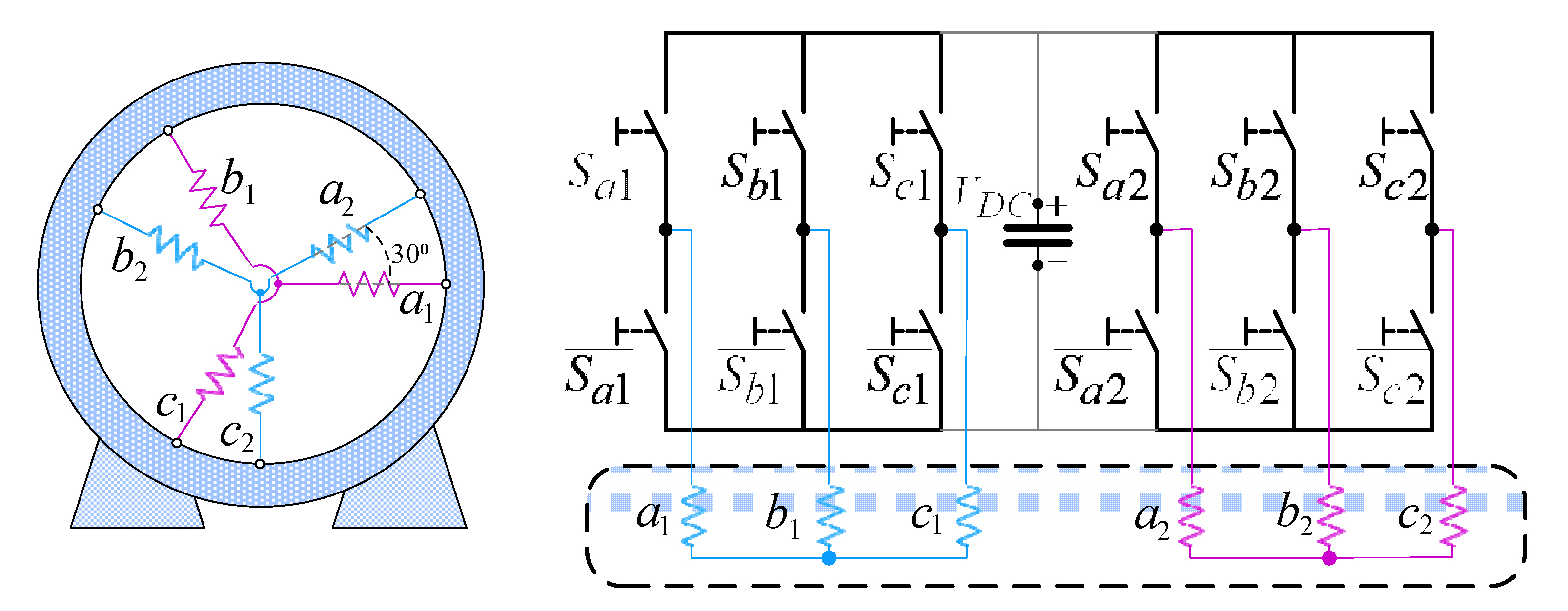
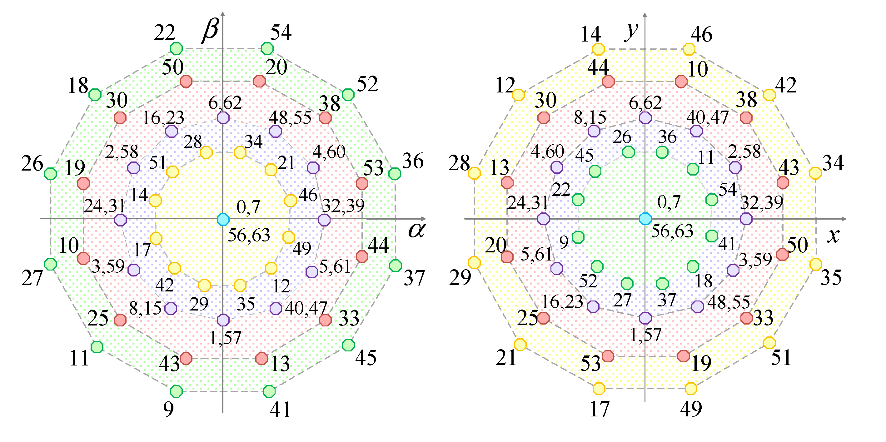
2. Six-Phase Electric Drive Generalities

The electric drive employed in this work is depicted in Figure 1. This topology is composed by an asymmetrical six-phase induction machine (IM) fed by a dual two-level three-phase voltage source converter (VSC). Concerning the IM, it is formed by two sets of three-phase windings spatially shifted 30 ° , where each winding set is connected to an isolated neutral point. The use of two neutral points permits increasing the DC-link voltage utilization and simplifying the control scheme [27].
This VSC configuration provides a total of   2 6 = 64 switching states that can be expressed as a vector, [ S ] = [ S a 1   S b 1   S c 1   S a 2   S b 2   S c 2 ] . Each component of [ S ] represents the behavior of one VSC leg. According to a well-known modeling, the state of these variables can be defined with a binary code, for instance, if the upper leg switch of phase a 1 is ON S a 1 =1 and S a 1 =0 when the opposite situation occurs. Using VSC switching states and the DC-link voltage, stator phase voltages ( v i j ) can be obtained as:
[ v a 1 v b 1 v c 1 v a 2 v b 2 v c 2 ] = V D C 3 · [ 2 1 1 0 0 0 1 2 1 0 0 0 1 1 2 0 0 0 0 0 0 2 1 1 0 0 0 1 2 1 0 0 0 1 1 2 ] · [ S a 1 S b 1 S c 1 S a 2 S b 2 S c 2 ] .
The stator phase variables can be expressed using diverse reference frames to simplify the understanding/control of the IM. Among all different reference frames and transformations available in the literature, the vector space decomposition (VSD) is one of the most popular choices [28]. When VSD is applied to stator phase variables, they can be referred to as three orthogonal subspaces with a clear physical meaning. The α - β plane is related to the flux/torque production, whereas the x - y plane is related to stator copper losses in distributed-winding machines. The zero-sequence subspace z 1 - z 2 can be omitted in this topology because the currents cannot flow in this plane.
To express phase variables into the VSD reference frame, the amplitude-invariant Clarke transformation matrix is employed [28]:
[ C ] = 1 3 · [ 1 1 / 2 1 / 2 3 / 2 3 / 2 0 0 3 / 2 3 / 2 1 / 2 1 / 2 1 1 1 / 2 1 / 2 3 / 2 3 / 2 0 0 3 / 2 3 / 2 1 / 2 1 / 2 1 1 1 1 0 0 0 0 0 0 1 1 1 ] ,
[ v α s   v β s   v x s   v y s   v 0 +   v 0 ] T = [ C ] · [ v a 1   v b 1   v c 1   v a 2   v b 2   v c 2 ] T ,
[ i α s   i β s   i x s   i y s   i 0 +   i 0 ] T = [ C ] · [ i a 1   i b 1   i c 1   i a 2   i b 2   i c 2 ] T .
Applying (2), stator phase voltages (1) can be mapped onto VSD variables. Figure 2 shows α - β and x - y maps for the considered topology, where each voltage vector has been appointed using a decimal number equivalent to the binary code of vector [ S ] . As shown in Figure 2, all active voltage vectors in the main plane also present an active location in the secondary plane. According to their α - β contribution, voltage vectors can be classified in five groups: large, medium-large, medium, small and null voltage vectors. These groups of switching states compose the available control actions in standard FCS-MPC.
Additional to the VSD simplification, the flux/torque production can be carried out in a decoupled manner if the rotating d - q reference frame is employed. Flux regulation is then related to the d -component, whereas torque production is dependent on the q -component. This transformation is obtained using the Park matrix as follows:
[ D ] = [ cos θ sin θ sin θ cos θ ] ,
where θ is the angle of the rotating reference frame that is calculated from the measured speed and the estimated slip [29].

3. PULLA-MPC Control Scheme

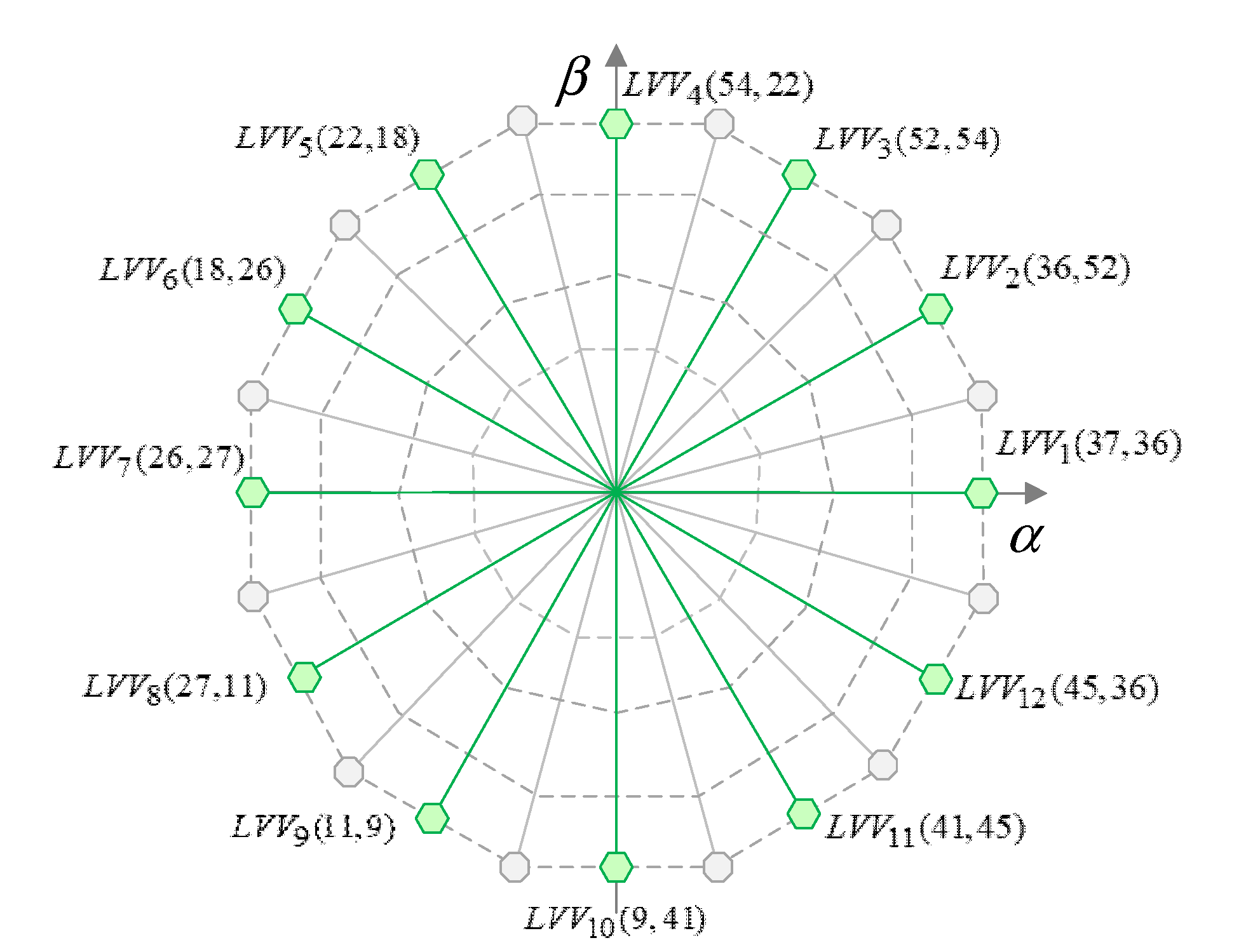
3.1. Control Actions in PULLA-MPC

FCS-MPC schemes can be classified as a direct control strategy since available switching states are directly evaluated in the machine model as control actions [5]. In the case of the developed PULLA-MPC scheme, the voltage outputs tested in the discretized predictive machine model are formed by a LVV [20] and an optimum null voltage vector. The formalization of this multiple voltage solution provides several advantages to reduce the voltage production in the secondary subspace [22]. On the one hand, the usage of LVVs as active voltage vectors reduces the x - y harmonic injection since these switching states are mapped as small voltage vectors in this subspace. As an additional improvement, a suitable regulation of the secondary subspace is achieved because these couples of large voltage vectors are shifted 150 ° . Then the control of the x - y plane can be done in open-loop mode [20]. Finally, the dynamic duty cycle of active and null voltage vectors suppresses the static nature of the LVVs, adapting the current injection in the secondary subspace related to the operating point.
On the other hand, the use of the defined set of control actions increases the α - β refinement in two manners:
  • Tangential α - β refinement: twelve LVVs can be selected to satisfy tangential requirements (Figure 3).
  • Radial α - β refinement: the application time of the null voltage vector, V n u l l , adapts radial requirements as a function of the working conditions.
To satisfy the radial voltage requirements, the active voltage application time,   t a p , is estimated as a ratio of the reference q -current, i q s * | k , and the rated q -current,   i q s | m a x ,
t a p = K · i q s * | k i q | m a x   ,
where K is a weighting factor defined to prioritize the critical role of the secondary subspace from the point of view of the current quality. With that in mind, this parameter is defined using a linear expression related to the torque production:
K = 0.901 + 0.022 · | i q s * | k | .
Therefore, in low-torque scenarios, the K parameter produces an extra active voltage reduction. The minimum value of this parameter has been established to avoid the degradation of the flux/torque current tracking. This value has been obtained using a trial-and-error method. On the other hand, in the maximum torque requirement ( | i q s * | k = 4.5   A ), the K parameter shows a unitary value to promote the role of the main plane from the point of view of the control objectives.
Considering the selected control actions and the application time defined in (5), the average voltage output per sampling period can be calculated as:
v o u t = t a p · ( 1 2 · V l 1 + 1 2 · V l 2 ) + ( 1 t a p ) · V n u l l ,
being V n u l l the optimum null switching state and V l 1 / V l 2 the two adjacent large voltage vectors that composed the LVV (see Figure 3).
The performance of the proposed control actions can also be analyzed in terms of switching losses. In this regard, the transition between two adjacent large voltage vectors only supposes a single change in the legs of the VSC [20] and hence, switching losses are reduced. Focusing on the transition from active to null voltage vectors, the number of switching changes can be reduced using the optimal null switching state for each LVV couple. In the six-phase electric drive under study, there are four different switching states with a null production in both subspaces. Thus, it is possible to optimize the selection of a null voltage vector according to the minimization of the switching frequency. To illustrate this procedure, L V V 6 ( V 18 , V 26 ) is considered as the optimum LVV selected in a sampling period. If a random null voltage vector, for example V 63 , is used, transition between V 26 and V 63   implies a total of three changes in the legs of the VSC (Figure 4a). Nonetheless, if the V 56 null voltage vector is selected, the switching state transition only involves two switch changes, as shown in Figure 4b. This optimization of the switching losses is done offline for each couple of large voltage vectors, in order to reduce the total computational burden.

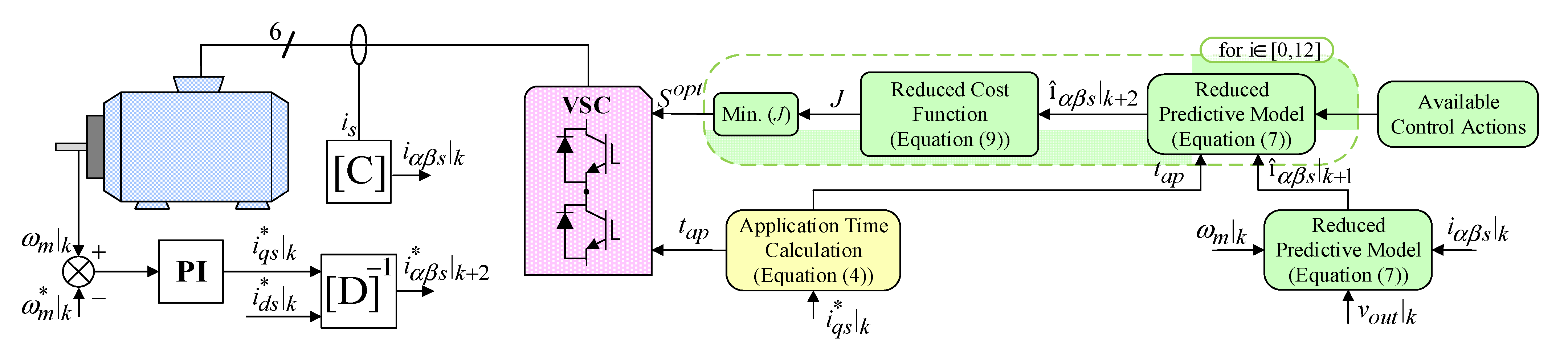
3.2. PULLA-MPC Scheme
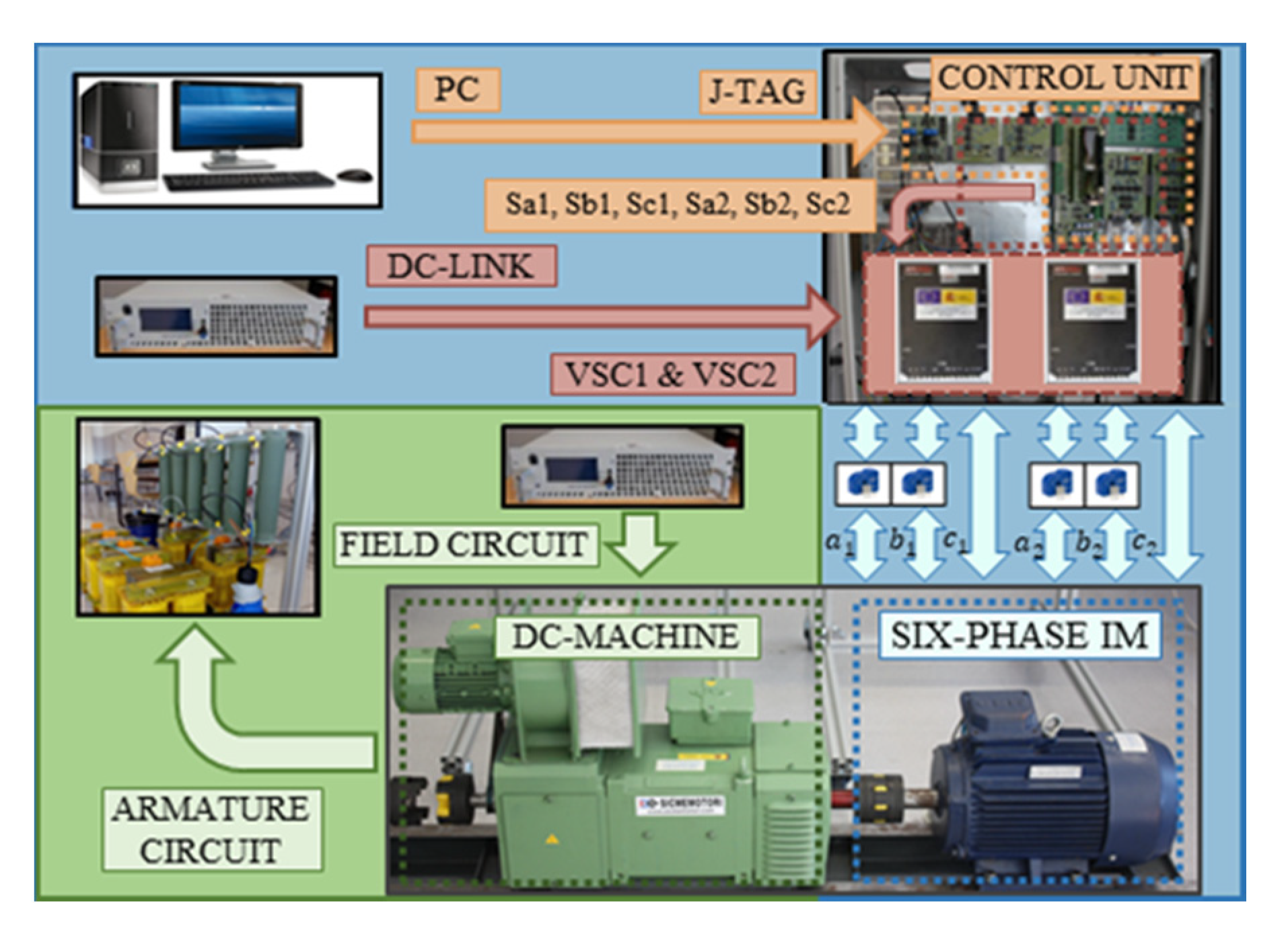
The proposed FCS-MPC is composed of an outer proportional-integer (PI) controller to regulate the speed and an inner current control loop using two-step prediction stages (see Figure 5). The PI controller provides the q -current reference whereas the d -current reference is fixed to its rated value to ensure nominal stator flux. The reference currents are compared with the predicted currents in order to select the optimum control action in each sampling period.
Focusing on the inner current control loop, a vector space decomposition (VSD) of the machine model is employed in both predictive stages to estimate future currents. Since the x - y current regulation is carried out in open-loop mode with the use of LVVs, a reduced machine model can be implemented:
d d t [ X α β ] = [ A ¯ ] · [ X α β ] + [ B ¯ ] · [ V α β ] ,
with
[ V α β ] = [ v α s   v β s   0     0 ] T ,     [ X α β ] = [ i α s     i β s     λ α r     λ β r ] T ,
where [ A ¯ ] and [ B ¯ ] are obtained from the six-phase IM equations [9], and α - β   fluxes/currents are represented with λ α β r and i α β s , respectively.
As shown in Figure 5, the predictive machine model is employed in the two stages of the inner current control loop of the proposed control scheme. For this reason, the proposed PULLA-MPC is based on a two-step prediction horizon ( k + 2 ) and, consequently, the one-step delay compensation approach is inherently included [5]. In the first stage, α - β predicted currents, î α β | k + 1 , are obtained using the mechanical speed, ω m | k , the voltage output of the previous control action, v o u t | k and the measured VSD stator currents, i α β s | k . Then, in the second stage, the predicted α - β currents in a k + 2 horizon, î α β | k + 2 , produced by each available control action are obtained and evaluated in a cost function to select the optimum switching states. As well as in the case of the discretized machine model, a reduced cost function can be defined:
J = ( i α s * î α s | k + 2 ) 2 + ( i β s * î β s | k + 2 ) 2
The proper PULLA-MPC capabilities to provide low harmonic distortion and reduced switching losses are confirmed in the next section in an experimental test bench.

4. Results

This section includes experimental results to confirm the suitable performance of the proposed control scheme when it is implemented in a multiphase electric drive. The goodness of PULLA-MPC is evaluated in five different tests. In Test 1, a preliminary version of the developed regulation technique is assessed. The control scheme (named as FPULLA-MPC) is implemented with a free selection of the applied null voltage vector to highlight the importance of the appropriate zero selection in the reduction of switching losses. Test 2 compares the proposed PULLA-MPC with an LVV-MPC in steady-state condition to evaluate the impact of the employed control actions on the overall harmonic current distortion. Finally, the dynamic response of the proposed PULLA-MPC is evaluated in Tests 3–5, using the LVV-MPC to analyze its transient capability.
The five experimental tests have been carried out in the test bench shown in Figure 6. The employed multiphase machine is an asymmetrical six-phase induction machine connected to a dual two-level three-phase VSC from Semikron (SKS22F) from Semikron, Nuremberg, Germany. The VSC is fed by a single DC-link. The parameters of the machine have been obtained using the AC time domain and stand-still with inverter supply tests (see Table 1) [30,31]. The control actions are executed by a digital signal processor from Texas Instrument (TMS320F28335) from TI, Dallas, Texas, USA. The connection with the microcontroller is made through a J-TAG connection and the software provided by Texas Instruments (Code Composer Studio). To apply a load torque to the multiphase machine, a DC-machine is coupled to its shaft. The armature of this DC-machine is connected to a variable passive resistance load that dissipates the power, being the load torque dependent on the speed.

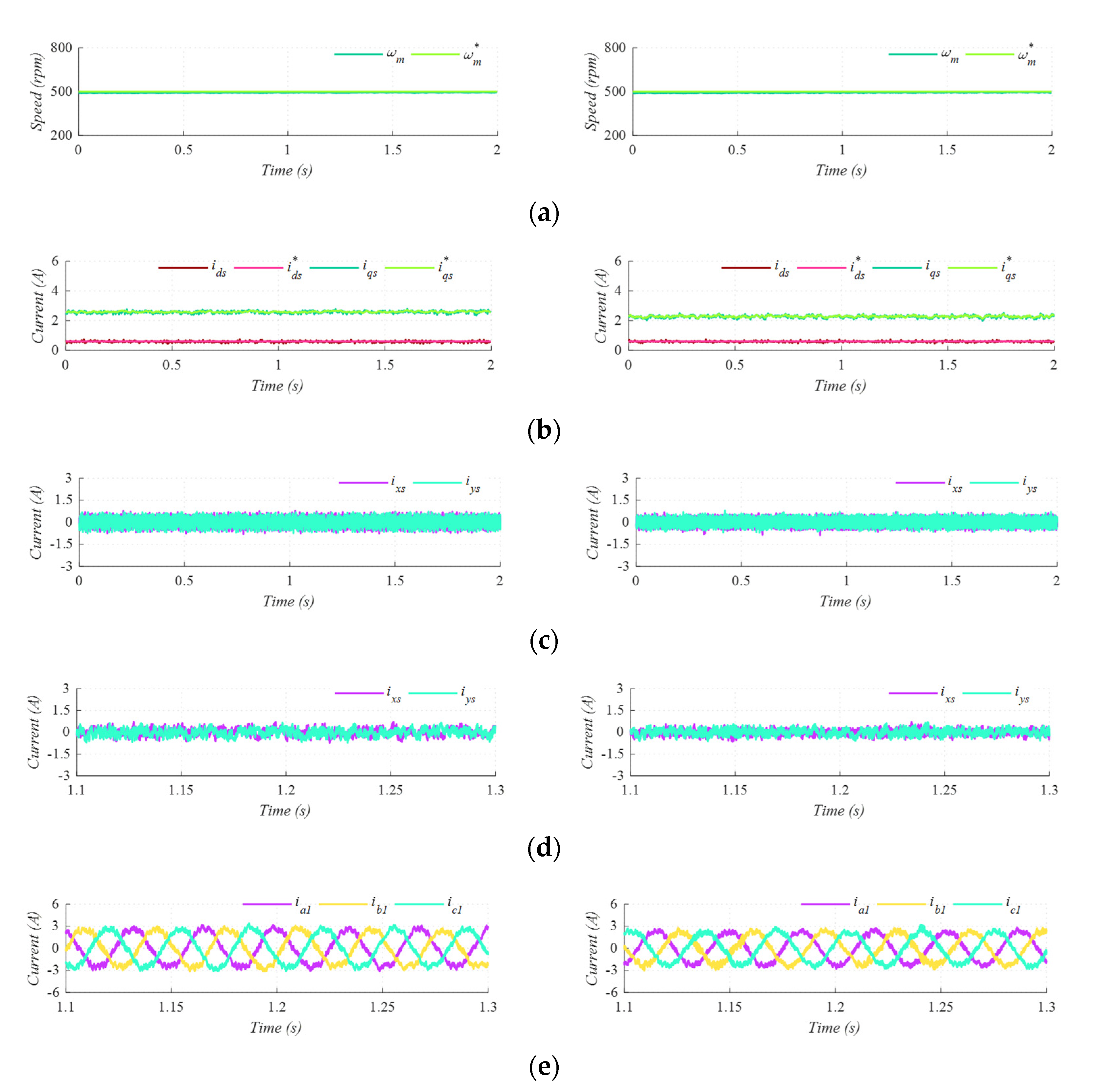
4.1. Test 1. Steady-State Performance of FPULLA-MPC and PULLA-MPC

In Test 1, the reference speed is set up at 500   rpm and load torque is equal to 3.75 Nm. The speed regulation is successfully achieved in both cases as shown in Figure 7a. The tracking of d - q currents and x - y currents is also suitable, regardless of the employed control scheme (Figure 7b,c). As shown in Figure 6d, the two control schemes also provide similar total harmonic distortion (THD) of stator phase currents (see Table 2), equal to 12.21% in the case of FPULLA-MPC and 11.61% when the optimization procedure is done. Nevertheless, the use of a sub-optimal null voltage vector increases significantly the VSC switching frequency and, therefore, switching losses also augment. The FPULLA regulation technique shows a switching frequency of 5.7 kHz (see Table 2), whereas in the proposed PULLA-MPC this value is reduced to 4.96 kHz (12.98% lower than in FPULLA-MPC) thanks to the null voltage vector optimization procedure. As a consequence of the lower switching frequency the losses related to VSC switching are also lower in the case of the PULLA-MPC. To sum up, the proposed PULLA-MPC achieves a similar current quality for a lower switching frequency.

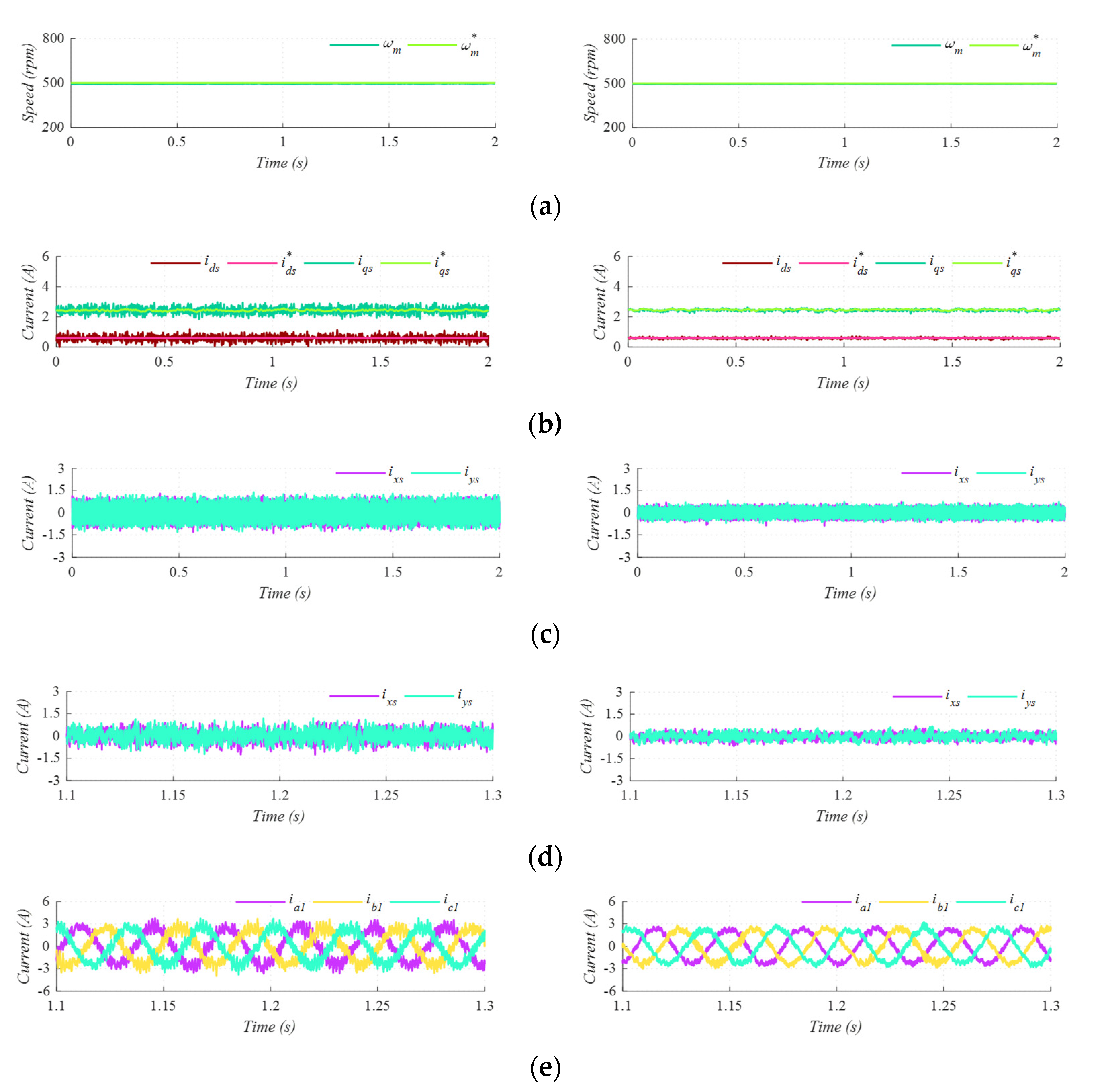
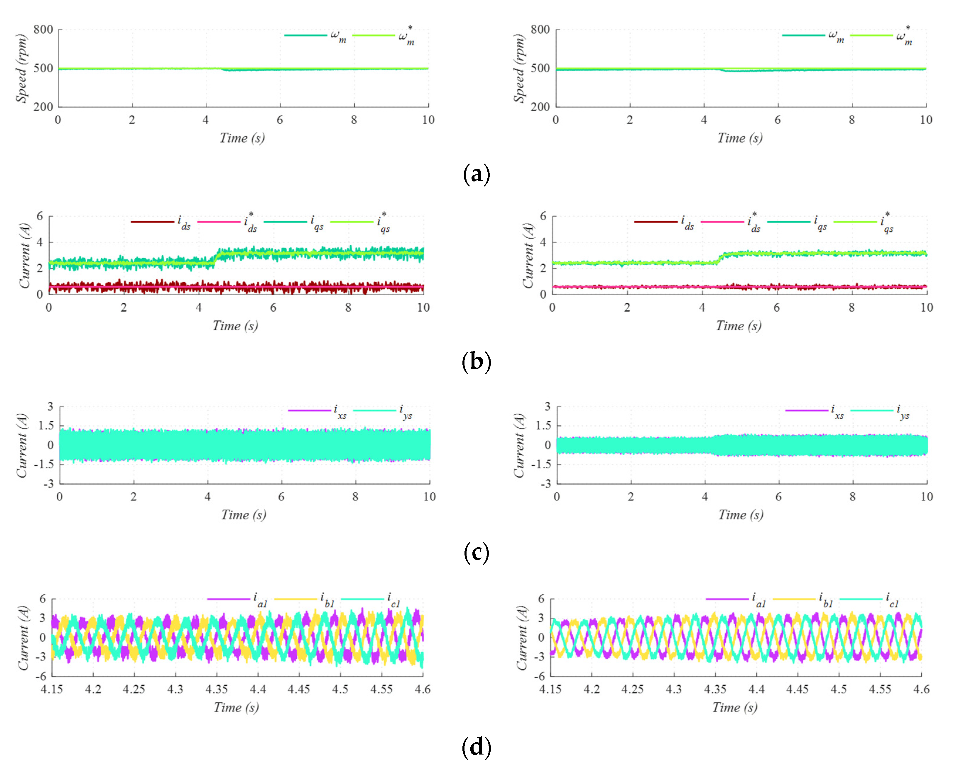
4.2. Test 2. Steady-State Performance of LVV-MPC and PULLA-MPC

In Test 2, the steady-state performance of LVV-MPC [24] and PULLA-MPC is evaluated. In both cases, the machine is operated at 500   r p m with a load torque of 4.12 Nm. Regardless of the selected control scheme, tracking of the mechanical speed and d - q currents is acceptably done (Figure 8a,b). From the point of view of the x - y current mitigation, PULLA-MPC presents a peak-to-peak value ( I x p p ) of   1.26   A , whereas in LVV-MPC this quality index increases up to 2.61   A . The lower ripple in PULLA-MPC is obtained because the combination of active and null voltage vectors eliminates the static nature presented in LVVs, mitigating the current injection in the secondary subspace. As a result of this improvement in the harmonic production, a lower THD of stator phase currents is obtained, achieving a reduction of 44.89% in comparison with LVV-MPC (Figure 8e). Table 3 shows quality indices and switching frequencies obtained in Test 2. On the other hand, stator copper losses and VSC switching losses are estimated and depicted in Table 4 to confirm the goodness of the proposed control technique from the point of view of the electric drive losses. The stator copper losses have been calculated using the stator resistance ( R s ) and the average rms value of the phase currents as follows:
P s t a t o r = 6 · R s · r m s ¯ p h 2 ,
whereas the switching losses have been obtained using the approach presented in [32] and the datasheet of the VSC employed in the test bench [33,34]. As shown in Table 4, the proposed PULLA-MPC provides lower total losses thanks to the significant reduction of the stator copper losses. Therefore, the better current quality indices provided by the PULLA-MPC also imply lower total losses in the electric drive.

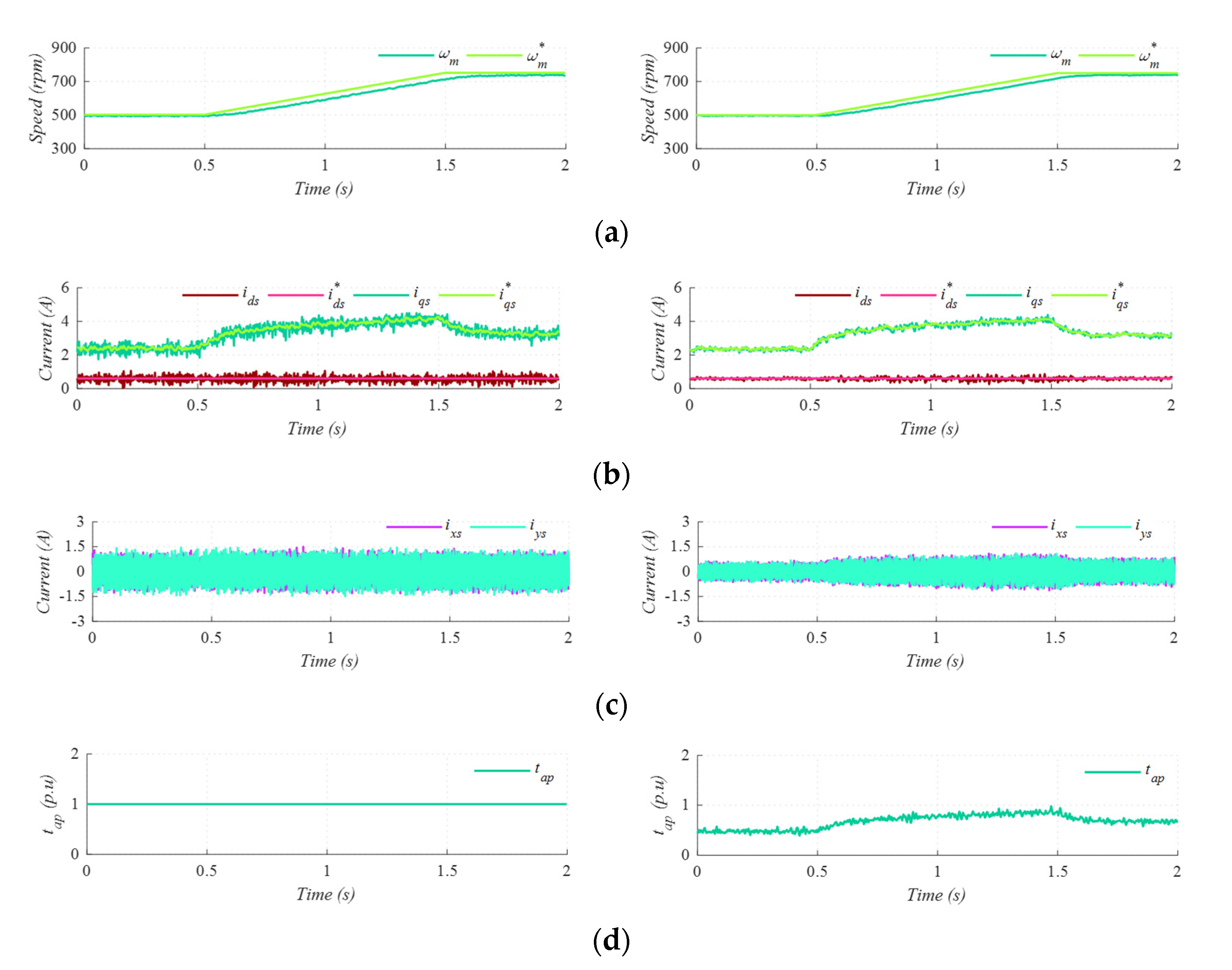
4.3. Test 3. Dynamic Performance of LVV-MPC and PULLA-MPC in a Speed-Ramp Scenario

Test 3 evaluates the capability of the proposed regulation strategy to provide a suitable dynamic response. For this purpose, reference speed varies from 500 rpm to 750 rpm in a ramp-wise manner (Figure 9a). To ensure a proper speed tracking, the q -current varies when the reference speed starts increasing its value (Figure 9b). Analyzing the trend of x - y currents (Figure 9c), the peak-to-peak value also increases when the machine accelerates because a higher active voltage production is necessary to satisfy the new operating point. To satisfy the test conditions, the application time increases its value according to the reference q -current (see Figure 9d). However, the proper combination of two adjacent large voltage vectors contributes to mitigate the excessive harmonic content in the secondary subspace. As shown in Figure 9, the proposed PULLA-MPC provides a similar dynamic response than in the case of LVV-MPC, but with a better mitigation of the secondary components.

4.4. Test 4. Dynamic Performance of LVV-MPC and PULLA-MPC in a Load Torque Step

As shown in Figure 10, a load torque step is carried out in Test 4. From the point of view of the dynamic response, both methods present a satisfactory performance (Figure 10a). However, in the case of the developed PULLA-MPC (right plots), the secondary currents are lower than in the case of the LVV-MPC (see Figure 10c). This result is obtained thanks to the combination of an active voltage vector with a null voltage vector during the control period. As a consequence of the adaptation of the voltage injection in the secondary subspace according to the operating point, the phase currents also show a lower harmonic content (see Figure 10d).

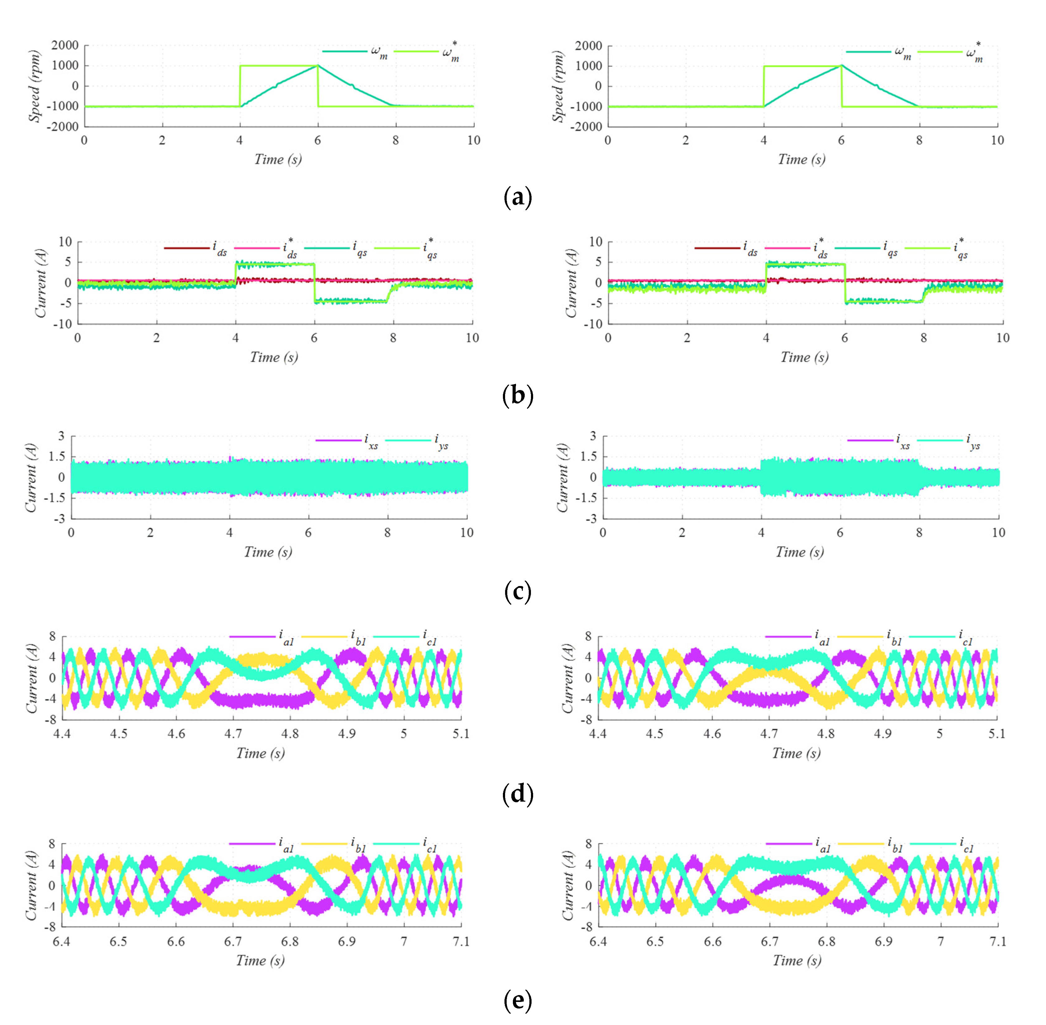
4.5. Test 5. Dynamic Performance of LVV-MPC and PULLA-MPC in a Double Reversal-Speed Test

Test 5 shows a double reversal-speed where the reference speed is set to −1000 rpm, 1000 rpm and −1000 rpm in the different speed areas (Figure 11a). Both methods present a suitable dynamic response for this demanding speed requirements (Figure 11). Nevertheless, in the case of the PULLA-MPC (right plots) the mitigation of the secondary components is better than in the case of LVV-MPC (left plots), since the injection of the secondary components is related to the operating point. Figure 11d,e show the phase currents at the point of zero-speed crossing.
Analyzing the presented results, the proposed PULLA-MPC provides additional advantages over previous works. Its main contributions are the following:
  • A suitable total harmonic distortion (44.89% lower than in LVV-MPC [20]).
  • A reduced switching frequency (12.98% lower than in FPULLA-MPC).
  • A low computational burden (73.39% lower than in the case of [22]).
  • A mitigated electric drive loss (see Table 4).
Therefore, based on these results, the proposed PULLA-MPC can be considered an interesting regulation strategy alternative with a reduced computational burden, a lower harmonic distortion and mitigated switching losses.

5. Conclusions

The proposed PULLA-MPC is designed as a multi-vectorial solution where the advantages of synthetized offline and online virtual control actions are combined. On the one hand, the considered control scheme presents a higher α - β refinement than a regulation scheme with an offline estimation of the control actions (LVV-MPC). In addition, thanks to the appropriate duty cycle estimation, the active voltage production in the secondary subspace is adapted attending to the operating condition. The decrease of the harmonic current components provokes an improvement in the performance of the multiphase machine. On the other hand, the algebraic solution employed to estimate the duty cycle of the active voltage vectors mitigates the computational burden derived from an online estimation of control actions. Finally, the optimal selection of the null voltage vector for each couple of adjacent large voltage vector significantly reduces the switching frequency and, consequently, the losses in the VSC.

Author Contributions

Conceptualization and methodology, A.G.-P., I.G.-P., M.J.D., J.C.-R., J.J.A. and P.S.-B.; software, A.G.-P., P.S.-B., J.C.-R. and I.G.-P.; validation I.G.-P. and M.J.D.; formal analysis and investigation, A.G.-P. and I.G.-P.; resources, M.J.D. and I.G.-P.; data curation, A.G.-P., I.G.-P., M.J.D., J.C.-R., J.J.A. and P.S.-B.; writing—original draft preparation, A.G.-P., I.G.-P., M.J.D., J.C.-R., J.J.A. and P.S.-B.; writing—review and editing, A.G.-P., I.G.-P., M.J.D., J.C.-R., J.J.A. and P.S.-B.; visualization, A.G.-P.; supervision, I.G.-P. and M.J.D.; project administration, I.G.-P. and M.J.D.; funding acquisition, I.G.-P. and M.J.D. All authors have read and agreed to the published version of the manuscript.

Funding

This research was funded by the Spanish Government under the Plan Estatal 2017–2020 with the reference RTI2018-096151-B-I00.

Conflicts of Interest

The authors declare no conflict of interest.

References

  1. Duran, M.J.; Levi, E.; Barrero, F. Multiphase Electric Drives: Introduction. In Wiley Encyclopedia of Electrical and Electronics Engineering; John Wiley & Sons, Inc.: Hoboken, NJ, USA, 2017; pp. 1–26. [Google Scholar]
  2. Levi, E.; Jones, M.; Vukosavi, S.N.; Toliyat, H.A. A novel concept of a multiphase, multimotor vector controlled drive system supplied from a single voltage source inverter. IEEE Trans. Power Electron. 2004, 19, 320–335. [Google Scholar] [CrossRef]
  3. Duran, M.J.; Gonzalez-Prieto, I.; Gonzalez-Prieto, A.; Barrero, F. Multiphase energy conversion systems connected to microgrids with inequal power-sharing capability. IEEE Trans. Energy Conv. 2017, 32, 1386–1395. [Google Scholar] [CrossRef]
  4. Levi, E.; Bojoi, R.; Profumo, F.; Toliyat, H.A.; Williamson, S. Multiphase induction motor drives—A technology status review. IET Electric Power Appl. 2007, 1, 489–516. [Google Scholar] [CrossRef] [Green Version]
  5. Gonçalves, P.F.C.; Cruz, S.M.A.; Mendes, A.M.S. Finite control set model predictive control of six-phase asymmetrical machines—An overview. Energies 2019, 12, 4693. [Google Scholar] [CrossRef] [Green Version]
  6. Gonzalez-Prieto, I.; Zoric, I.; Duran, M.J.; Levi, E. Constrained model predictive control in nine-phase induction motor drives. IEEE Trans. Energy Conver. 2019, 34, 1881–1889. [Google Scholar] [CrossRef]
  7. Luo, Y.; Liu, C. A flux constrained predictive control for a six-phase PMSM motor with lower complexity. IEEE Trans. Ind. Electron. 2019, 66, 5081–5093. [Google Scholar] [CrossRef]
  8. Iqbal, A.; Alammari, R.; Mosa, M.; Abu-Rub, H. Finite set model predictive current control with reduced and constant common mode voltage for a five-phase voltage source inverter. In Proceedings of the IEEE 23rd International Symposium on Industrial Electronics (ISIE), Istanbul, Turkey, 1–4 June 2014; pp. 479–484. [Google Scholar]
  9. Gonzalez-Prieto, I.; Duran, M.J.; Aciego, J.J.; Martin, C.; Barrero, F. Model predictive control of six-phase induction motor drives using virtual voltage vectors. IEEE Trans. Ind. Electron. 2018, 65, 27–37. [Google Scholar] [CrossRef]
  10. Garcia-Entrambasaguas, P.; Zoric, I.; Gonzalez-Prieto, I.; Duran, M.J.; Levi, E. Direct torque and predictive control strategies in nine-phase electric drives using virtual voltage vectors. IEEE Trans. Power Electron. 2019, 34, 12106–12119. [Google Scholar] [CrossRef] [Green Version]
  11. Xue, C.; Song, W.; Wu, X.; Feng, X. Constant switching frequency finite-control-set predictive current control scheme of a five-phase inverter with duty-ratio optimization. IEEE Trans. Power Electron. 2018, 33, 3583–3594. [Google Scholar] [CrossRef]
  12. Xue, C.; Song, W.; Feng, X. Finite control-set model predictive current control of five-phase permanent-magnet synchronous machine based on virtual voltage vectors. IET Electr. Power Appl. 2017, 11, 836–846. [Google Scholar] [CrossRef]
  13. Luo, Y.; Liu, C. Multi-Vectors based model predictive torque control for a six-phase PMSM motor with fixed switching frequency. IEEE Trans. Energy Conv. 2019, 34, 1369–1379. [Google Scholar] [CrossRef]
  14. Gonçalves, P.F.C.; Cruz, S.M.A.; Mendes, A.M.S. Fixed and variable amplitude virtual vectors for model predictive control of six-phase PMSMS with single neutral configuration. In Proceedings of the 2019 IEEE International Conference on Industrial Technology (ICIT), Melbourne, Australia, 13–15 February 2019; pp. 267–273. [Google Scholar]
  15. Luo, Y.; Liu, C. Elimination of harmonic currents using a reference voltage vector based-model predictive control for a six-phase PMSM motor. IEEE Trans. Power Electron. 2019, 34, 6960–6972. [Google Scholar] [CrossRef]
  16. Aciego, J.J.; Gonzalez Prieto, I.; Duran, M.J. Model predictive control of six-phase induction motor drives using two virtual voltage vectors. IEEE J. Emerg. Sel. Top. Power Electron. 2019, 7, 321–330. [Google Scholar] [CrossRef]
  17. Gonçalves, P.F.C.; Cruz, S.M.A.; Mendes, A.M.S. Predictive current control of six-phase permanent magnet synchronous machines with modulated virtual vectors. In Proceedings of the IECON 2019—45th Annual Conference of the IEEE Industrial Electronics Society, Lisbon, Portugal, 14–17 October 2019; pp. 6229–6234. [Google Scholar]
  18. Tatte, Y.N.; Aware, M.V. Torque ripple and harmonic current reduction in a three-level inverter fed direct-torque-controlled five-phase induction motor. IEEE Trans. Ind. Electron. 2017, 64, 5265–5275. [Google Scholar] [CrossRef]
  19. Yu, B.; Song, W.; Tang, T.; Wang, S.; Bin, P.Y. A Finite control set model predictive current control scheme for five-phase PMSMS based on optimized duty ratio. In Proceedings of the 2019 IEEE Applied Power Electronics Conference and Exposition (APEC), Antheim, CA, USA, 17–21 March 2019. [Google Scholar]
  20. Duran, M.J.; Gonzalez-Prieto, I.; Gonzalez-Prieto, A. Large virtual voltaje vectors for direct controllers in six-phase electric drives. Int. J. Electron. Power Energy Syst. 2021, 125, 106425–106433. [Google Scholar] [CrossRef]
  21. Aciego, J.J.; Gonzalez-Prieto, I.; Duran, M.J.; Bermudez, M.; Sales-Biedma, P. Model predictive control based on dynamic voltage vectors for six-phase induction machines. IEEE J. Emerg. Sel. Top. Power Electron. 2020. [Google Scholar] [CrossRef]
  22. Gonzalez-Prieto, A.; Gonzalez-Prieto, I.; Duran, M.J. Smart voltage vectors for model predictive control of six-phase electric drives. IEEE Trans. Ind. Electron. 2021, 68, 9024–9035. [Google Scholar] [CrossRef]
  23. Ayala, M.; Doval-Gandoy, J.; Rodas, J.; Gonzalez, O.; Gregor, R.; Rivera, M. A Novel Modulated Model Predictive Control Applied to Six-Phase Induction Motor Drives. IEEE Trans. Ind. Electron. 2021, 68, 3672–3682. [Google Scholar] [CrossRef]
  24. Xheng, L.; Fletcher, J.E.; Williams, B.W.; He, X. A novel direct torque control scheme for a sensorless five-phase induction motor drive. IEEE Trans. Ind. Electron. 2011, 58, 503–513. [Google Scholar]
  25. Pandit, J.K.; Aware, M.V.; Nemade, R.; Tatte, Y. Simplified implementation of synthetic vectors for DTC of asymmetric six-phase induction motor drives. IEEE Trans. Ind. Appl. 2018, 54, 2306–2318. [Google Scholar] [CrossRef]
  26. Ren, Y.; Zhu, Z.Q. Reduction of both harmonic current and torque ripple for dual three-phase permanent-magnet synchronous machine using modified switching-table-based direct torque control. IEEE Trans. Ind. Electron. 2015, 62, 6671–6681. [Google Scholar] [CrossRef]
  27. Che, H.S.; Levi, E.; Jones, M.; Hew, W.P.; Rahim, N.A. Current control methods for an asymmetrical six-phase induction motor drive. IEEE Trans. Power Electron. 2014, 29, 407–417. [Google Scholar] [CrossRef] [Green Version]
  28. Zhao., Y.; Lipo, T.A. Space vector PWM control of dual three-phase induction machine using vector space decomposition. IEEE Trans. Ind. Appl. 1995, 31, 1100–1109. [Google Scholar] [CrossRef]
  29. Gonzalez-Prieto, I.; Duran, M.J.; Barrero, F.; Bermudez, M.; Guzman, H. Impact of postfault flux adaptation on six-phase induction motor drives with parallel converters. IEEE Trans. Power Electron. 2017, 32, 515–528. [Google Scholar] [CrossRef] [Green Version]
  30. Yepes, A.G.; Riveros, J.A.; Doval-Gandoy, J.; Barrero, F.; Óscar, L.; Bogado, B.; Jones, M.; Levi, E. Parameter identification of multiphase induction machines with distributed windings-part 1: Sinusoidal excitation methods. IEEE Trans. Energy Conv. 2012, 27, 1056–1066. [Google Scholar] [CrossRef]
  31. Riveros, J.A. Parameter identification of multiphase induction machines with distributed windings-part 2: Time-domain techniques. IEEE Trans. Energy Conv. 2012, 27, 1067–1077. [Google Scholar] [CrossRef]
  32. Hossein, H.; Faranda, R. A New Approach for Power Losses Evaluation of IGBT/Diode Module. Electronics 2021, 10, 280. [Google Scholar]
  33. Nicolai, U.; Wintrich, A. Application Note AN 1403, Determining Switching Losses of SEMIKRON IGBT Modules. SEMIKRON International GmbH. 2014. Available online: https://www.semikron.com/service-support/downloads/detail/semikron-application-note-determining-switching-losses-of-semikron-igbt-modules-en-2014-08-19-rev-00.html (accessed on 12 July 2021).
  34. Datasheet IGBT SK30GB128 Modules. SEMIKRON International GmbH. 2006. Available online: https://datasheetspdf.com/pdf-file/831859/SemikronInternational/SK30GAL128/1 (accessed on 12 July 2021).
Figure 1. Selected six-phase electric drive topology.
Energies 14 04358 g001
Figure 2. Voltage vectors in α - β and x - y subspaces for an asymmetrical six-phase induction machine fed by a dual three-phase VSC.
Energies 14 04358 g002
Figure 3. Available large voltage vectors in α - β subspace.
Energies 14 04358 g003
Figure 4. Switching transition: (a) Arbitrary null voltage vector selection and (b) using an optimal null voltage vector selection.
Energies 14 04358 g004
Figure 5. Proposed PULLA-MPC control scheme.
Energies 14 04358 g005
Figure 6. Test bench.
Energies 14 04358 g006
Figure 7. Test 1. Steady-state performance of FPULLA-MPC (left) and PULLA-MPC (right). From top to bottom: (a) motor speed, (b) d - q currents, (c) x - y currents, (d) zoom of the x - y currents, and (e) set 1 of phase currents.
Energies 14 04358 g007
Figure 8. Test 2. Steady-state performance of LVV-MPC (left) and PULLA-MPC (right). From top to bottom: (a) motor speed, (b) d - q currents, (c) x - y currents, (d) zoom of the x - y currents and (e) set 1 of phase currents.
Energies 14 04358 g008
Figure 9. Test 3. Dynamic performance of LVV-MPC (left plots) and PULLA-MPC (right plots). From top to bottom: (a) motor speed, (b) d - q currents, (c) x - y currents and (d) application time of active voltage vectors.
Energies 14 04358 g009
Figure 10. Load torque step test for LVV-MPC (left plots) and PULLA-MPC (right plots). From top to bottom: (a) motor speed, (b) d - q currents, (c) x - y currents and (d) set 1 of phase currents.
Energies 14 04358 g010
Figure 11. Double reversal-speed test for PULLA-MPC. From top to bottom: (a) motor speed, (b) d - q currents, (c) x - y currents, (d) zoom 1 of set 1 of phase currents and (e) zoom 2 of set 1 of phase currents.
Energies 14 04358 g011
Table 1. Summary IM parameters.
Power 1   kw
Maximum q -current ( i q | m a x )4.5 A
Stator Resistance ( R s ) 14.2   Ω
Rotor Resistance ( R r ) 3   Ω
Mutual Inductance ( L m ) 420   mH
Stator Leakage Inductance ( L l s ) 3.5   mH
Rotor Leakage Inductance ( L l r ) 55   mH
DC-Link Voltage ( V D C ) 300   V
Table 2. Total harmonic distortion and switching frequency in Test 1.
Control MethodTHD f s w i t c h i n g
PULLA-MPC11.61%4.96 kHz
FPULLA12.65%5.70 kHz
Table 3. Quality indices and switching frequencies for Test 2.
Control MethodTHD I x p p   f s w i t c h i n g r m s ¯ p h 2
PULLA-MPC10.94%1.79 A 4.9 kHz3.219 A 2
LVV-MPC19.85%2.66 A 3.4 kHz3.375 A 2
Table 4. Electric drives losses.
LossesLVV-MPCPULLA-MPC
Stator copper losses (W)285.32269.94
VSC switching losses (W)7.9211.07
Total (W)293.24281.01
Publisher’s Note: MDPI stays neutral with regard to jurisdictional claims in published maps and institutional affiliations.

